


Fisher Paykel DG7027G1, DE7027G1, DE7027P2 User Manual
|
|
AeroCare clothes dryer |
Installation instructions |
|
and User guide |
US

 WARNING!
For your safety the information in this manual must be followed to minimize the risk of fire or explosion or to prevent property damage, personal injury or death.
—Do not store or use gasoline or other flammable vapors and liquids in the vicinity of this or any other appliance.
—WHAT TO DO IF YOU SMELL GAS
•Do not try to light any appliance.
•Do not touch any electrical switch; do not use any phone in your building.
•Clear the room, building or area of all occupants.
•Immediately call your gas supplier from a neighbor’s phone. Follow the gas supplier’s instructions.
•If you cannot reach your gas supplier, call the fire department.
—Installation and service must be performed by a qualified installer, service agency or the gas supplier.
The Governor of California is required to publish a list of substances known to the state of California to cause cancer or reproductive harm and requires business to warn customers of potential exposures to such substances.
WARNING!: Gas appliances contain or produce substances, which can cause death, or serious illness and which are known to the State of California to cause cancer, birth defects, or other reproductive harm. To reduce the risk from substances in fuel or from fuel combustion, make sure this appliance is installed, operated, and maintained according to the manufacturer’s instructions.
In the Commonwealth of Massachusetts
Installation of this appliance must be performed by a contractor, plumber or gasfitter who is qualified or licensed by the state.
Contents |
|
|
|
1 |
|
|
||
Introduction |
2 |
|
Important safety instructions |
3 |
|
Installation instructions |
7 |
|
The first time you turn your dryer on |
48 |
|
Getting started quickly |
50 |
|
AeroCare controls |
54 |
|
Sorting and loading |
56 |
|
Dryer cycles |
58 |
|
Drying special items |
63 |
|
Drying cycle options |
65 |
|
Dryer operation |
68 |
|
Care labels |
70 |
|
Drying rack |
71 |
|
Customizing dryer cycles |
72 |
|
Changing pre-set options |
73 |
|
Caring for your dryer |
75 |
|
Before you call for service |
78 |
|
User warnings |
|
|
Fault codes |
78 |
|
Solving operating problems |
79 |
|
Solving drying problems |
82 |
|
Limited warranty |
84 |
|
How to get service |
86 |
|
Important!
SAVE THESE INSTRUCTIONS
The models shown in this User Guide may not be available in all markets and are subject to change at any time. For current details about model and specification availability in your country, please visit our website listed on the back cover or contact your local Fisher & Paykel dealer.
Registration
Register your product with us so we can provide you with the best service possible.
To register your product visit our website: www.fisherpaykel.com

2 Introduction
Thank you for buying a Fisher & Paykel AeroCare clothes dryer. We are very proud of this dryer and trust it will serve you well for many years.
At Fisher & Paykel we aim to provide innovative products that are simple to use, ergonomic, energy efficient and kind to the environment. Thousands of tonnes of washing and 80 years of laundry experience have been programmed into your dryer to help give you the best possible performance.
We have developed this dryer to treat your clothes with the utmost care, drying them gently, so they will look better for longer. We trust you’ll enjoy the benefits of numerous drying cycles and options, and its extra large capacity.
Please take the time to read this User Guide carefully. It will help you to operate and maintain your new AeroCare dryer. Your safety and the safety of others is very important. Located on your dryer and throughout this guide are safety messages and instructions; it is important that you understand and follow them.
We hope you enjoy your new dryer.
Fig.1 AeroCare dryer models
Important!
It is important that this User Guide should be retained with your AeroCare clothes dryer for future reference. Should the appliance be sold or transferred to another owner, please ensure that the User Guide is left with the appliance. This will ensure that the new owner can familiarize themselves with the information and warnings contained within the Guide.

Important safety instructions 3
Symbols
Symbols will be used in this Guide to highlight when extra care is required. Abide by these at all times to minimize the risk of harm while operating the dryer.
It is important to always act with caution and use common sense when operating your dryer. Use only as instructed by the User Guide.
This is the safety alert symbol. This symbol alerts you to hazards that can hurt you and others, or even cause death.
The safety alert symbol and the word WARNING will precede all safety messages. This word means:
|
WARNING |
You could be killed or seriously injured if you don’t |
|
follow instructions. |
|
|
|
|
All safety messages will identify the potential hazard, tell you how to reduce the chance of injury, and tell you what can happen if the instructions are not followed.

4 Important safety instructions
 WARNING!
Electric Shock Hazard
Follow the safety precautions outlined in this User Guide.
Failure to do so can result in death or electrical shock.
Important safety precautions
■■Read all instructions carefully before using this dryer. Use this dryer only for its intended purpose as described in this User Guide.
■■Installation must conform with local codes, or in absence of local codes, with the National Fuel Gas Code, ANSI Z223.1/NFPA 54 or the Canadian Natural Gas and Propane Installation Code, CSA B149.1
■■Installation and service must be performed by a qualified or licensed contractor, plumber or gasfitter qualified or licensed by the state, province, or region where this appliance is being installed.
■■This dryer must be properly installed and located in accordance with the Installation Instructions before it is used.
■■This dryer, when installed, must be electrically grounded in accordance with local codes, or in the absence of local codes, with the National Electrical Code, ANSI/NFPA 70, or the Canadian Electrical Code, CSA C22.1.
■■Do not install or store the dryer where it will be exposed to water or exposed to the weather.
■■Connect to a properly protected, rated and sized power supply circuit to avoid electrical overload.
■■Do not repair or replace any part of the appliance or attempt any servicing, unless specifically recommended in the published user repair instructions that you understand and have the skills to carry out.
■■To minimize the possibility of electric shock, unplug this dryer from the power supply or disconnect the dryer at the household distribution panel (by removing the fuse or switching off the circuit breaker) before attempting any user maintenance or cleaning.
■■When disconnecting the dryer, pull by the plug rather than the cord or junction of the cord plug, to avoid damage to the cord or junction of the cord plug.
■■Make sure the cord is located so that it will not be stepped on, tripped over or otherwise subject to stress or damage.
■■Do not tamper with the controls.
■■Note: Touching the POWER button does NOT disconnect the dryer from the power supply, even though the lights are out.
■■Do not operate this dryer if it is damaged, malfunctioning, partially disassembled or has missing or broken parts, including a damaged cord or plug.
■■This dryer must be directly connected to an approved fixed electrical outlet. It cannot be plugged into an extension cord or an adaptor plug.
■■Do not use the dryer if there is water on the floor near the dryer. Call an Authorized Service Agent if there is a leak.

Important safety instructions 5
 WARNING!
Fire Hazard
Only dry fabrics that have been washed with water.
Do not use a drying cycle with heat to dry articles containing foam rubber or similarly textured rubber-like materials. Only dry on the AIR DRY cycle.
A clothes dryer produces combustible lint and must be exhausted outdoors. Take care to prevent the accumulation of lint around the exhaust opening and in the surrounding area.
Do not use fabric softeners or products to eliminate static unless recommended by the manufacturer of the fabric softener or product.
Failure to follow these instructions can result in death or personal injury.
To reduce the risk of fire in a tumble dryer the following should be observed:
■■Do not place items in a tumble dryer that have previously been cleaned in, washed in, soaked in, or spot cleaned with flammable liquids or solids. They give off vapors which are a fire or explosion hazard. Highly flammable substances commonly used in domestic environments include acetone, denatured alcohol, gasoline, kerosene, some brands of spot removers and dry cleaning solvents, turpentine, waxes, wax removers, vegetable oil, fish oil, massage oil, and cooking oil.
■■Do not place items exposed to cooking oils in your dryer. Items contaminated with cooking oils may contribute to a chemical reaction that could cause a load to catch fire.
■■Do not leave hot oil-affected items in a pile or stack. This can prevent heat from escaping and can create a fire hazard. Oil-affected items can ignite spontaneously, especially when exposed to heat sources such as a tumble dryer. The items become warm causing an oxidation reaction in the oil. This oxidation creates heat. If the heat cannot escape the items can become hot enough to catch fire.
■■Do not use a drying cycle with heat to dry items containing rubber, foam rubber, plastic or similar materials (such as padded bras, bath mats, rugs, bibs, baby pants, plastic bags, pillows etc), as these materials might melt or burn. Some rubber materials when heated can under certain circumstances produce fire by spontaneous combustion. Only dry on the AIR DRY cycle.
■■Unless specifically recommended by their manufacturer, do not use fabric softeners or similar products in a tumble dryer.
■■Do not store or use gasoline or other flammable gases and liquids near this or any other appliance.
■■Keep the area around the exhaust opening and adjacent surrounding areas free from the accumulation of combustible materials such as lint, dust, dirt, paper, rags, chemicals etc.
■■Do not store any items that may burn or melt (such as paper materials, plastics or plastic containers etc) next to the dryer.
■■Clean the lint filter each time you use the dryer, before or after each load.
■■The dryer must be exhausted to the outside. Carefully follow the exhausting and venting details in the Installation Instructions.
■■The interior of the appliance and the exhaust duct should be cleaned periodically by qualified service personnel.

6 Important safety instructions
Use of the dryer
■■Do not allow children to play inside, on, around or with this dryer or any other appliance. Close supervision is necessary if this dryer is used near children.
■■Never climb on, climb into, or stand on the dryer top, or drum, or apply weight to the door.
■■Keep the floor around your dryer clean and dry to reduce the possibility of slipping.
■■If your dryer is running and you want to unload or add clothes, touch START/PAUSE then open the dryer door.
■■Do not reach into the appliance if the drum is moving.
■■Undergarments that contain metal reinforcements should not be placed directly in the dryer. Damage to the dryer can result if the metal reinforcements come loose during drying. If you wish to dry these items use the drying rack supplied with your dryer.
■■BEFORE THE APPLIANCE IS REMOVED FROM SERVICE OR DISCARDED, REMOVE THE DOOR.
SAVE THESE INSTRUCTIONS
|
|
|
Installation instructions |
|
|
7 |
|
|
|
|
 WARNING! – Risk of fire
Clothes dryer installation must be performed by a qualified installer.
Install the clothes dryer according to the manufacturer’s instructions and local codes.
DO NOT install the clothes dryer with flexible plastic venting materials. If flexible metal (foil-type) duct is installed, it must be identified by the dryer manufacturer as suitable for use with clothes dryers and installed in strict accordance with the instructions found on pages 26 to 38 of these installation instructions. Flexible venting materials are known to collapse, be easily crushed and trap lint. These conditions will obstruct dryer airflow and increase the risk of fire.
The dryer must be vented to the outdoors.
Use only rigid metal 4”(102 mm) diameter ductwork inside the dryer cabinet and use only UL-listed transition ducting between the dryer and the home duct.
Do not install or store this appliance in any location where it could be exposed to water and/or weather.
To reduce the risk of severe injury or death, follow all installation instructions.
SAVE THESE INSTRUCTIONS
Before you begin
Read the important safety instructions on the inside cover and on pages 3 – 6 before you start installing the dryer.
Check to make sure you have all the tools and parts necessary to correctly install this appliance.
Tools required:
■■Adjustable wrench 10” (254 mm) × 2 (for gas connection).
■■Flat-blade screwdriver.
■■Slip joint pliers.
■■Pipe wrench 8” (203 mm) (for gas connection).
■■Phillips screwdriver.
■■Drill with 1/8” (3 mm) drill bit (for bottom venting only).
■■Caulking gun and compound (for installing new exhaust vent).
■■Glasses.
■■Gloves.
■■Knife.
■■Hacksaw.
■■Spirit level.

8 Installation instructions
Materials:
■■4” (102 mm) diameter rigid metal duct (recommended).
■■4” (102 mm) diameter UL-listed flexible metal duct (if needed).
■■4” (102 mm) diameter metal elbow(s).
■■Flexible metal gas line connector (for gas connections only).
■■Duct or spring clamps (2).
■■Pipe joint compound (pipe dope or tape) for gas pipe connections, resistant to LP Propane, butane and natural gas (for gas connections only).
■■Exhaust/vent hood.
■■Duct tape.
■■Soap solution for gas leak detection (for gas connections only).
■■¾” (19 mm) strain relief (electric connections only).
■■Dryer power cord kit (power cord is not supplied with United States models).
Requirement: UL-rated 120/240 V, 30 amp with 3 or 4 prongs. Identify the plug type needed from the existing house receptacle before purchasing. Length of cord must be at least 5 feet (1.5 m) long.
To the installer
Read these instructions completely and carefully.
■■These instructions must be left with the home owner for future reference.
■■Correct installation is the responsibility of the installer.
■■Installation of this appliance must be performed by a qualified installer.
■■The dryer must be exhausted to the outdoors.
■■Remove the door from an old dryer before it is removed and discarded.
■■The wiring diagram and service information can be found in the control console.
■■The limited warranty does not cover product failure as a result of improper installation.
■■The dryer must be installed in a location where the temperature is above 50°F (10°C) to ensure suitable operation of the dryer control system.
■■UL-listed duct material must be used. Discard existing plastic or metal foil duct and replace with UL-listed duct material.
■■Observe all governing codes and ordinances.
■■Follow the installation instructions carefully.
Important!
■■Save these instructions for local electrical inspector’s use.
■■Observe all governing codes and ordinances.
■■Install the clothes dryer according to the manufacturer’s instructions and local codes.
|
|
|
Installation instructions |
|
|
9 |
|
|
|
|
Unpacking
To ensure the best performance from the dryer, please follow the instructions below.
 WARNING!
Excess Weight Hazard
Use two or more people to move and install the dryer.
Failure to do so can result in back or other injury.
Important!
Only remove the packaging at the customer’s premises.
This will ensure the appliance arrives in pristine condition and reduces the risk of damage during transportation to the customer’s home.
1. Remove packaging
Remove all of the outer packaging. Dispose of unwanted packaging thoughtfully.
2. Discard packing material from around dryer feet
Tilt the dryer sideways and remove the foam shipping pads by pulling at the sides and breaking them away from the dryer feet. Be sure to remove all the foam pieces before continuing with installation.
3. Drying rack (selected models only)
Open the door. Remove the tape holding the drying rack in place. Remove the rack and remove protective tape from ‘legs’ of rack.
4. Accessories
Remove the accessories from inside the dryer.
Fig.2 Unpacking your dryer correctly

10 Installation instructions
Location requirements
 WARNING!
Explosion Hazard
Keep flammable materials and vapors, such as gasoline, away from the dryer.
Place dryer at least 18”(460 mm) above the floor for a garage installation. Failure to do so can result in death, explosion, fire, or burns.
The dryer must be installed or stored in an area which is not exposed to water or weather.
It is extremely important that the dryer is installed in a well ventilated location. This dryer must exhaust air outdoors. Do not install the dryer in any room or closet which does not permit the free flow of replacement air. The free area of any opening for the introduction of outside air shall not be less than twice the area of the dryer exhaust outlet.
The area in which the dryer is located must be kept clear and free from combustible materials, gasoline and other flammable vapors and liquids. A dryer produces combustible lint so the area around the dryer must be cleaned regularly to keep it free of lint.
Make sure dryer is in a suitable location for installation.
Consider installing the dryer before the washing machine in a side by side installation, this will allow better access to electrical and exhaust connections.
Installation instructions 11
Minimum clearance required other than alcove or closet installation
Allow sufficient room behind the dryer for the exhaust. The air intake is at the rear of the dryer. Ensure that there is a sufficient air passage on each side of the dryer for intake air.
The minimum clearance to combustible surfaces and for air openings are: 1” (25 mm) clearance both sides, 2” (51 mm) clearance at the front, and 1” (25 mm) clearance at the rear, or 5” (127 mm) clearance if the dryer exhaust duct is at the rear. Consideration must also be given to provide adequate clearance for proper operation and service.
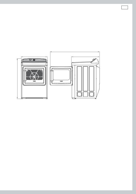
27” (683 mm)
41 1/2” (1051 mm)* |
* Excludes adjustable foot height
Fig.3 AeroCare dimensions
52 1/2” (1332 mm)
29 1/2” (743 mm)

12 Installation instructions
Requirements for alcove or closet installation
Your dryer is approved for installation in an alcove or closet (as specified on the dryer back).
 WARNING!
When installing a dryer in a closet alcove it MUST be exhausted to the outdoors. No other fuel burning appliance can be installed in the same closet or alcove.
The total ventilation area must be a minimum of 60 sq. in. (387 cm2) of open area equally distributed. If the closet contains both a washer and a dryer, doors must contain a minimum of 120 sq. in. (774 cm2) of open area equally distributed. The openings must never be obstructed (a louvered door with the minimum air opening is acceptable). Minimum installation clearances are required but more clearance is recommended.
|
|
|
|
minimum clearance |
|
|
|
|
required |
|
|
|
|
56 5/16” (1430 mm) |
1” (25 mm) |
1” (25 mm) |
1” (25 mm) |
min 2” (50 mm) |
min 1” (25 mm) |
|
|
|
|
(rear of product to wall) |
|
|
|
Fig.4 Minimum clearances |
|
total ventilation area 120 in.sq (774 cm2)
Fig.5 Minimum ventilation

Installation instructions 13
Requirements for alcove or closet installation continued
■■The closet should be vented to the outdoors to prevent gas pocketing in case of a gas leak in the supply line.
■■No other fuel-burning appliance shall be installed in the same closet with the dryer (gas models only).
Note: when the exhaust duct is located at the rear of the dryer, minimum clearance required from the wall is 5” (127 mm).
Bathroom or bedroom installation
The dryer MUST be vented to the outdoors. See “Exhausting the dryer” (page 26).
Mobile or manufactured home installation
Installation is required to comply with the Manufactured Home Construction & Safety Standard, title 24 CFR, part 3280. If or when such standard is not applicable, installation must comply with the American National Standard for Mobile Home, ANSI/NFPA No. 501.
■■The dryer MUST be vented to the outdoors with the termination securely fastened to the mobile home structure.
■■Exhaust ducts MUST be securely fastened to a non-combustible portion of the mobile home structure.
■■The exhaust MUST NOT be terminated beneath a mobile or manufactured home.
■■The exhaust duct material MUST BE METAL.
■■The exhaust duct MUST NOT be connected to any other duct, vent, or chimney, or be vented into a wall, ceiling or concealed space of a building.
■■Do not use sheet metal screws or other fastening devices which extend into the interior of the exhaust vent.
In addition to the above, for gas dryer models:
■■Kit 14-D346-33 MUST be used to attach the dryer securely to the structure.
■■Provide an opening with a free area of at least 25 sq. in. (161 cm2) for introduction of outside air into the dryer room.
Residential garage installation
Dryers installed in residential garages must be elevated 18” (460 mm) above the floor.
The installation must conform with local codes or, in the absence of local codes, with the National Electrical Code, NFPA NO. 70 (for electric dryers) or National Fuel Gas Code,
ANSI Z223.1/NFPA54 (for gas dryers) in the United States; and the Canadian Electrical Code CSA C22.1 (for electric dryers) or Natural Gas and Propane Installation Code, CSA B149.1 (for gas dryers), in Canada.

14 Installation instructions
Connecting a gas dryer (skip for electric dryer)
Refer to page 7 for tools required.
Note: installation and service of this dryer must be performed by a qualified installer, service agency or the gas supplier.
Gas supply and installation requirements
In the Commonwealth of Massachusetts:
■■Installation of the dryer must be completed by a plumber or gas fitter licensed by the state.
■■When using ball-type gas shut-off valves, the t-handle type shall be used.
■■If using a flexible gas connector, this must not exceed a length of 3 feet in total.
 WARNING!
Explosion Hazard
Installations must be performed by a qualified or licensed contractor, plumber, or gasfitter qualified or licensed by the state, province, or region where this appliance is being installed.
Use a new AGA or CSA approved gas supply line. Install a shut-off valve in an accessible place.
Only use a gas shut-off valve approved for use within the state, province, or region where this appliance is being installed.
Securely tighten all gas connections.
If connecting to LP Gas, have a qualified person make sure gas pressure does not exceed 13”(330 mm) water column.
Failure to follow these instructions can result in death, explosion, or fire.

Installation instructions 15
 WARNING!
To Reduce the Risk of Fire, Electrical Shock and Personal Injury:
Before connecting the dryer turn off circuit breaker(s) or remove the dryer’s circuit fuses at its electrical box. Ensure the power cord is unplugged from the wall socket.
Ensure the gas shut off valve in the supply line is OFF.
Use only new ducting materials. Remove and discard old flexible gas connector and duct material.
Gas type
This gas dryer is equipped with a valve and burner assembly for use only with natural gas. Your local service organization can convert this dryer for use with propane (LP) gas, using conversion kit WC254C1258A001.
Important!
All conversions must be completed by correctly trained and qualified personnel, in accordance with all local codes and ordinances.
Pressure testing
■■The dryer must be disconnected from the gas supply piping system during any pressure testing of the system at a pressure greater than 0.5 psi (3.5 kPa).
■■The dryer must be isolated from the gas supply piping system by closing the equipment shut-off valve during any pressure testing of the gas supply piping of test pressure equal to or less than 0.5 psi (3.5 kPa).
Gas supply
■■A 1/8” National Pipe Taper (NPT) plugged tapping must be installed immediately upstream of the gas supply connection to the dryer. This must be accessible for test gauge connection. Please contact your local gas utility if you have questions regarding the installation of the plugged tapping.
■■The gas supply line is to be 1/2” (12.7 mm) rigid pipe. The line must be equipped with an accessible shut-off which is within 6 feet (1.8 m) of the dryer AND in the same room as the appliance.
■■Pipe thread compound appropriate for Natural or Propane (LP) gas must be used.
■■New flexible metal gas line connector should be used to connect the dryer and gas supply.

16 Installation instructions
Elevation adjustment
■■The input ratings of gas operated clothes dryers are based on their operation at sea level, and need not be adjusted for operation at or below 2000 ft. (610 m) elevation. For operation at elevations above 2000 feet (610 m), input ratings should be reduced at a rate of four percent per 1000 feet (305 m) elevation above sea level.
■■Installation must conform to all local codes and ordinances. In the absence of local codes and/or ordinances, installation shall conform to the National Fuel Gas Code, ANSI Z223.1/NFPA 54, or the Natural Gas and Propane Installation Code, CSA B149.1.
Gas supply connection
2 1/2” (64 mm) |
|
1 3” (45 mm) |
3/8” NPT Male thread gas supply |
|
Note: add to vertical dimension the |
|
distance between cabinet bottom to floor |
Fig.6 Gas connection at rear of dryer |

Installation instructions 17
Connecting the dryer to the gas supply
Gas connection parts
Ensure you have the following parts before installing the dryer.
|
Adapter |
|
New metal flexible |
|
|
gas line connector |
1/8” NPT pipe plug for |
|
|
checking gas inlet pressure |
|
Adapter |
Shut-off valve |
|
Elbow |
||
|
||
3/8” NPT |
|
|
Pipe size at least 1/2” (12.7 mm) |
Fig.7 Parts required for gas connection |
Connecting to dryer
■■Install a female 3/8” NPT elbow at the gas inlet end of the dryer.
■■Attach a 3/8” flare union adapter to the female NPT elbow.
Apply pipe compound to the adapter and dryer gas inlet threads
Fig.8 Attaching elbow and adapter
Important!
Using two adjustable wrenches tighten the flexible gas line connection
Fig.9 Tighten connections
Securely hold on to the end of the dryer gas inlet with a pipe wrench to help prevent twisting the inlet.

18 Installation instructions
Connecting to supply
Apply pipe |
Plugged |
compound to |
Tapping |
all male threads |
|

 Shut-off valve
Fig.10 Connecting supply
Using two adjustable wrenches tighten all connections
Fig.11 Tightening supply connections
Important!
Do not over tighten the connections.
Test for gas leaks
 WARNING!
NEVER use an open flame to test for gas leaks.
■■Turn on the gas (open the gas shut off valve).
■■All connections should be checked for leaks with a soapy, or equivalent solution. Apply a soap (or equivalent) solution to the connection points. If leaks are found, close the shut-off valve, re-tighten the joint, then repeat the test.
Note: Do not use a solution that contains ammonia. This may cause damage to the brass fittings.
Open gas valve
Fig.12 Testing for gas leaks
Installation instructions 19
 WARNING!
Fire and Poisoning Hazard
Gas leaks cannot always be detected by the sense of smell. Use of an approved UL or CSA gas detector is recommended.
If a gas leak is detected follow the“What to do if you smell gas”instructions, stated on the inside font cover of this user guide.

20 Installation instructions
Electrical connection information for gas dryers
 WARNING!
Electrical Shock Hazard
Make sure appliance is wired or plugged into a grounded outlet.
Improper connection of the equipment-grounding conductor can result in a risk of electric shock. Check with a qualified electrician or service person if you are in doubt as to whether the appliance is properly grounded.
Do not modify the plug if it will not fit the outlet.
Have the proper outlet installed by a qualified electrician. Do not use an adaptor.
Do not use an extension cord.
Failure to follow these instructions can result in death, fire or electrical shock.
The appliance must be electrically grounded in accordance with all local codes and ordinances. In the absence of local codes, the dryer must be electrically grounded in accordance with the National Electrical Code, ANSI/NFPA NO. 70, or the Canadian Electrical Code, CSA C22.1.
Electrical requirements for gas dryers
The power supply must be 120V, 60Hz, and connected to a properly grounded branch circuit, which is protected by a 15 or 20 amp circuit breaker, or a time-delay fuse.
If the electrical supply provided does not meet specifications outlined above, the installation of an approved outlet by a licensed electrician is recommended.
Important!
The dryer is supplied with a three-prong (grounding) plug for your protection against electric shock. The plug should be plugged directly into a correctly grounded three prong power socket.
DO NOT cut or remove the grounding terminal from this plug.
Ensure proper ground exists before use.
If local codes permit, an external 

 ground wire (not provided), which


 meets local codes, may be added by


 attaching to the green ground screw


 on the rear of the dryer, and to a


grounded metal cold water pipe or other established ground.
Ensure proper ground exists before use

Installation instructions 21
Connecting an electric dryer (skip for gas dryers) – in the United States only
Refer to page 7 for tools required.
Electrical requirements (electric models only)
 WARNING!
To reduce the risk of fire, electrical shock & personal injury:
The appliance must be correctly grounded electrically, in accordance with all local codes and ordinances. In the absence of these, the appliance shall be grounded in accordance with the National Electrical Code ANSI/NFPA No. 70.
Before connecting the dryer, turn off the circuit breaker(s) or remove the dryer’s circuit fuses at its electrical box. Ensure the power cord is unplugged from the wall outlet.
DO NOT leave the cover off the terminal block.
Never use an extension cord or adapter plug with the dryer.
Use only new ducting materials. Remove and discard old duct material.
 WARNING!
Electric Shock Hazard
Use a new UL/CSA-listed 30-ampere power cord. Use a UL-listed strain relief.
Disconnect power before making electrical connections. Connect neutral wire (white or center wire) to center terminal.
On all four wire installations remove the grounding link and connect the ground wire to the green ground connecting screw.
Connect remaining two supply wires to remaining two terminals. Securely tighten all electrical connections.
Failure to do so can result in death, fire, or electrical shock.
Note: the wiring diagram is located in the control console.
The dryer must be plugged into or connected to an individual branch circuit, protected by the correct time delay fuses or circuit breakers. The power supply must be a 3- or 4-wire, single phase, 120/240 V, 60 Hz, 30 amp circuit.

22 Installation instructions
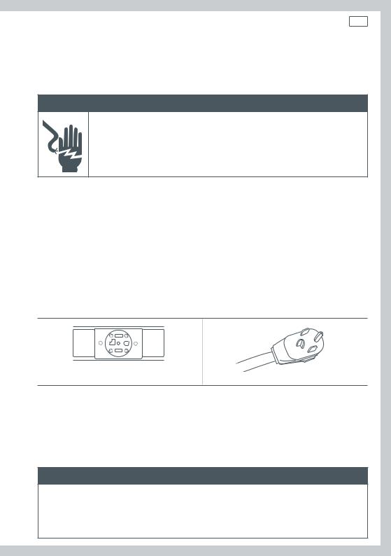
If your outlet looks like this |
Choose this power supply cord |
|
|
|
|
3-wire
(NEMA type 10-30R) |
(See 3-wire connection) |
|
|
4-wire
(NEMA type 14-30R) |
(See 4-wire connection) |
|
|
■■If a power cord is used, this must be plugged into a 30 amp socket only.
■■The power cord is NOT supplied with electric model dryers in the United States.
Contact a licensed electrician if the electricity supply does not meet the required specifications.
Grounding instructions
This dryer MUST be connected to a grounded metal, permanent wiring system. Alternatively, an equipment grounding conductor must be run with the circuit conductors and connected to the equipment grounding terminal on the dryer.
 WARNING!
Improper connection of the equipment-grounding conductor can result in a risk of electric shock. Check with a qualified electrician or service representative if you are in doubt as to whether the appliance is properly grounded.

Installation instructions 23
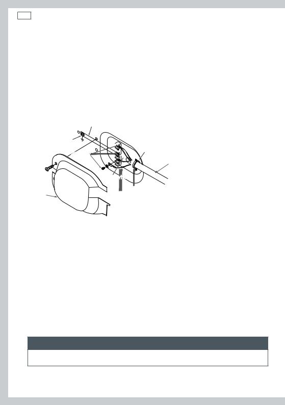
Connecting the dryer using 4-wire connection (must be used for mobile home installation)
Note: the National Electrical Code requires that new constructions use a 4-wire connection to an electric dryer (effective as of January 1, 1996). Where local codes do not permit grounding through the neutral, a 4-wire cord must also be used.
Important!
New constructions must NOT use a 3-wire connection.
Remove ground strap and discard. Keep green ground screw
Screws (3)
Cover
Hot wire
|
Relocate green ground screw here |
||
L1 |
|
Green or yellow wire |
|
N |
|
Strain relief bracket |
|
L2 |
|
||
|
4 #10 awg minimum copper conductors, |
||
|
|
||
|
|
or 120/240V 30 amp power supply cord kit |
|
Neutral (white) |
(min length: 5 feet (1.5 m)) marked for use with |
||
dryers and provided with closed loop or spade |
|||
|
|
||
|
|
terminals with upturned ends (not supplied) |
|
Hot wire
¾" (19 mm), UL recognized strain relief
Fig.14 4-wire connections
1Turn off the circuit breaker(s) (30 amp).
2Ensure the dryer cord is unplugged from the wall outlet.
3Locate and remove the power cord cover at the lower rear of the dryer.
4Remove and discard the ground strap. Retain the green ground screw for later relocation (Step 7).
5Install a ¾” (19 mm) UL-recognized strain relief to the entry hole for the power cord. Move the power cord through the strain relief.
6Connect the power cord according to the following:
a Connect the two hot lines to the outer screws of the terminal block (labelled L1 and L2). b Connect the neutral (white) line to the center of the terminal block (labelled N).
7Use the green ground screw to attach the ground wire of the power cord (ie relocate the green ground screw to the hole above strain relief bracket).
8Tighten all three terminal block screws completely.
9Correctly secure the power cord to the strain relief.
10Replace the power cord cover.
 WARNING!
NEVER leave the power cord cover off the terminal block.
24 Installation instructions
Connecting the dryer using 3-wire connection
Important!
■■DO NOT use in Canada.
■■DO NOT use for Mobile home installations, on new constructions, or on recreational vehicles.
■■NOT for use in areas where local codes prohibit grounding through the neutral conduction.
If required by local codes, install an external ground (not provided) to grounded metal, a cold water pipe or other established ground as determined by a quali ed electrician.
Ground strap
Hot wire
Green ground screw
Screws (3)
L1

 N
N  L2
L2 

Neutral (white)
Strain relief bracket
3 #10 awg minimum copper conductors, or 120/240V 30 amp power supply cord kit
(min length 5 feet (1.5 m)) marked for use with dryers and provided with closed loop or spade terminals with upturned ends (not supplied)
Cover |
Hot wire ¾" (19 mm), UL recognized strain relief |
Fig.15 3-wire connections
1Turn off the circuit breaker(s) (30 amp).
2Ensure the dryer cord is unplugged from the wall outlet.
3Locate and remove the power cord cover at the lower rear of the dryer.
4Install a ¾” (19 mm) UL-recognized strain relief to the entry hole for the power cord. Move the power cord through the strain relief.
5Connect the power cord according to the following:
a Connect the two hot lines to the outer screws of the terminal block (labelled L1 and L2). b Connect the neutral (white) line to the center of the terminal block (labelled N).
6Ensure the ground strap is connected to neutral (center) terminal of block, and to the green ground screw on located on the cabinet rear.
7Tighten all three terminal block screws completely.
8Correctly secure the power cord to the strain relief.
9Replace the power cord cover.
 WARNING!
NEVER leave the power cord cover off the terminal block.
Installation instructions 25
Connecting an electric dryer (skip for gas dryers) – in Canada only
Electrical requirements (electric models only)
 WARNING!
Electric Shock Hazard
Plug appliance into grounded 4 prong outlet.
Failure to do so can result in death or electric shock.
Note: the wiring diagram is located in the control console.
It is your responsibility to:
■■Contact a qualified electrical installer.
■■Ensure the electrical connection is adequate and conforms with Canadian Electrical Code, C22.1 and all local code requirements.
■■Plug the dryer into, or connect the dryer to an individual branch circuit, which is protected by the correct time delay fuses or circuit breakers. The power supply must be a 4-wire, single phase, 120/240 V, 60Hz, 30 amp circuit.
This dryer is supplied with a CSA approved power cord (5 feet (1.52 m) in length, intended for plugging into a 14-30R wall outlet. Ensure the outlet is within reach of the dryer’s final location.
4-wire
(NEMA type 14-30R)
A replacement power cord is available, if required. Use of part number 248C1014G001 (240 V cord set) is recommended. Contact Fisher & Paykel Customer Care (refer to page 86).
Grounding instructions
This dryer MUST be connected to a grounded metal, permanent wiring system.
 WARNING!
Improper connection of the equipment-grounding conductor can result in a risk of electric shock. Check with a qualified electrician or service representative if you are in doubt as to whether the appliance is properly grounded. Do not modify the plug provided with the dryer.
26 Installation instructions
Exhausting the dryer
Refer to page 7 for tools required.
 WARNING!
Fire Hazard
The dryer must be vented to the outdoors.
Use rigid or thick wall flexible metal exhaust duct only.
Do not use a plastic exhaust duct.
Do not use a metal foil exhaust duct.
Failure to follow these instructions can result in death or fire.
■■This dryer must be vented to the outdoors. This will prevent the build up of lint and moisture in the room in which it is located and reduce the risk of fire.
■■Use only 4” (102 mm) rigid metal ducting material for the home exhaust duct.
■■Use only 4” (102 mm) rigid metal or UL-listed flexible metal (semi-rigid or foil-type) duct material to connect the appliance to the home exhaust duct. The ducting must be installed according to the instructions found in the section “Connecting the dryer to the house vent” (page 29).
■■The dryer must not under any circumstances be exhausted into a chimney, a wall, a ceiling, gas vent, crawl space, attic, under an enclosed floor, or into any concealed space of a building.
■■Never vent the dryer into a common duct with an exhaust system originating from a kitchen. The combination of grease and lint creates a potential fire hazard.
■■Ducting must be kept as short in length and as straight as possible. Ducts can accumulate lint and create a potential fire hazard. Do not exceed the maximum exhaust duct lengths stated later in these installation instructions (page 33).
■■Never install a screen in or over the dryers exhaust duct. The screen will cause lint to accumulate, creating a potential fire hazard.
■■Use duct tape to secure joints in the ducting. Do not use screws as these will extend into the duct system, accumulate lint and create a potential fire hazard.
■■Never obstruct incoming or exhausted air.
■■Ensure access is provided for inspection and cleaning of the exhaust. This is particularly important at turns and joints. The exhaust system shall be inspected and cleaned annually.
■■The dryer is set up for rear exhausting. If space available for installation is limited, the dryer can be vented directly from the sides or bottom of the cabinet. Refer to pages 35 to 38.
 Loading...