

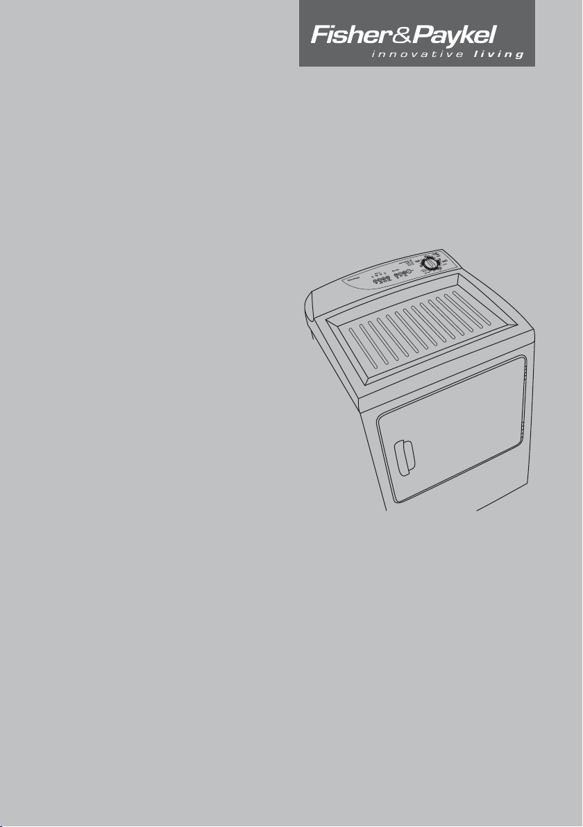
Dryer
Installation Instructions and
User Guide US CA
Secadora
Instrucciones de Instalación y
Guía del Usuario ES
New Zealand Australia USA Canada Europe Asia Pacific
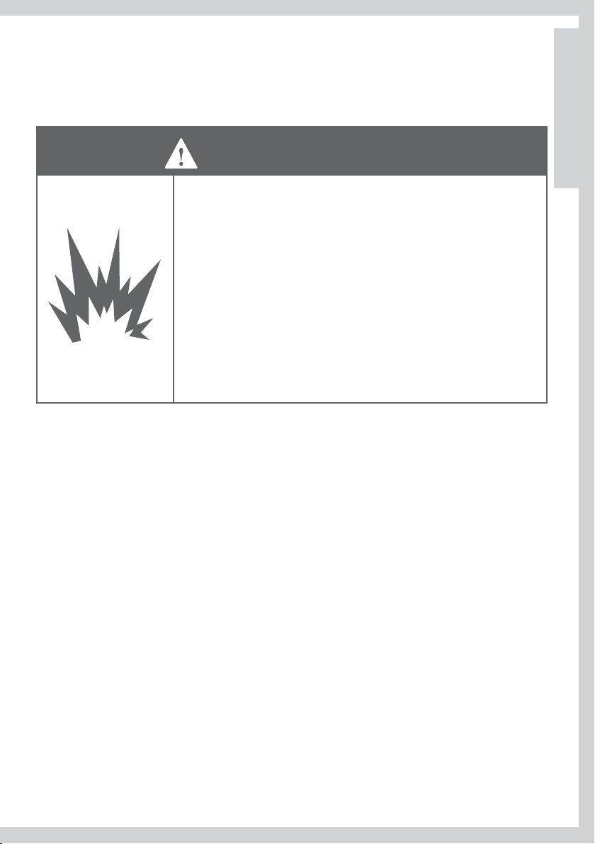
WARNING: For your safety the information in
this manual must be followed to minimize the risk
of fire or explosion or to prevent property damage,
personal injury or death.
— Do not store or use gasoline or other flammable vapors
and liquids in the vicinity of any other appliance.
— WHAT TO DO IF YOU SMELL GAS
t Do not try to light any appliance.
t
Do not touch any electrical switch; do not use any
phone in your building.
t Clear the room, building or area of all occupants.
t
Immediately call your gas supplier from a neighbor’s
phone. Follow the gas supplier’s instructions
t
carefully.
If you cannot reach your gas supplier, call the fire
department.
— Installation and service must be performed by a
qualified installer, service agency or the gas supplier.
English Page 2 – 48
Español Pág 49 – 98
The Governor of California to publish a list of substances known to the state of
California to cause cancer or reproductive harm and requires businesses to warn
customers of potential exposures to such substances.
Gas appliances contain or produce substances, which can cause death, or serious
illness and which are known to the State of California to cause cancer, birth
defects, or other reproductive harm. To reduce the risk from substances in fuel
or from fuel combustion, make sure this appliance is installed, operated, and
maintained according to the manufacturers instructions.
In the state of Massachusetts
Installation must be performed by a qualified or licensed contractor, plumber, or gasfitter
qualified or licensed by the state.
2

Contents
Dryer Safety 5
Important Safety Instructions 6
Warranty 8
Installation Instructions 9
Installer Responsibilities, Location Requirements 10
Dimensions 12
Exhausting 13
Maximum Length of Exhaust Duct 15
Alternative Exhaust Directions 17
Exhaust Venting 19
Installation 20
Grounding Instructions 21
Electrical Requirements 22
Gas Requirements 25
Level Machine, Final Installation Check List 28
Features 29
Operating Instructions 30
Reversing the Door 32
Quick Start / Using Your Dryer 33
Care Labels 38
Drying Special Items 39
Other Features 41
Cleaning 42
Trouble Shooting 44
Limited Warranty 46
US
CA
3
Thank you for buying a Fisher & Paykel dryer.
We hope you enjoy using the dryer as much as we have enjoyed designing it. We’ve gone to a lot
of effort to ensure it treats your clothes with the utmost care, drying them gently so they will look
better for longer. We know you’ll enjoy the benefits of its easy loading drum.
Please take the time to read this User Guide carefully. It will help you operate and maintain your
new dryer.
Your safety, and the safety of others is very important. Located
on your dryer and throughout this guide are safety messages and
instructions; it is important that you understand and follow them.
4
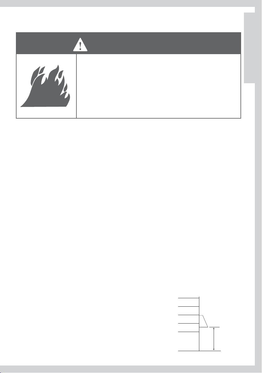
Dryer Safety
WARNING
Fire Hazard
To reduce the risk of re, electric shock, or injury to persons, read
the IMPORTANT SAFETY INSTRUCTIONS before operating this
appliance.
Failure to follow to do so can result in death or electric shock.
Symbols
Symbols will be used in this Guide to highlight when extra care is required. Abide by these at all
times to ensure you and your family are not harmed while operating your dryer.
It is important to always act with caution and use common sense when operating your dryer. Use
only as per instructed by the User Guide.
This is the safety alert symbol. This symbol alerts you to hazards that can kill
or hurt you and others.
US
CA
The safety alert symbol and the word DANGER or WARNING will precede all
safety messages. These words mean:
You can be killed or seriously injured if you don’t
DANGER
WARNING
All safety messages will identify the hazard, tell you how to reduce the chance of injury, and
tell you what can happen if the instructions are not followed.
immediately follow instructions.
You can be killed or seriously injured if you don’t follow
instructions.
5
Important Safety Instructions
WARNING
Electric Shock Hazard
Follow the safety precautions outlined in this User Guide.
Failure to do so can result in death or electric shock.
Safety Precautions
Read all instructions carefully before using this dryer.
Use this dryer only for its intended purpose as described in this User Guide.
To minimize the possibility of electric shock, unplug this dryer from the power supply or
disconnect the dryer at the household distribution panel (by removing the fuse or switching off
the circuit breaker) before attempting any user maintenance or cleaning.
Installation must conform with local codes, or in absence of local codes, with the National Fuel Gas
Code, ANSI Z223.1/NFPA 54 or the Canadian Natural Gas and Propane Installation Code, CSA B149.1.
Installations and service must be performed by a qualified or licensed contractor, plumber or
gasfitter qualified or licensed by the state, province, or region where this appliance is being installed.
This dryer must be properly installed a
before it is used.
This dryer, when installed, must be electrically grounded in accordance with local codes, or in the
absence of local codes, with the National Electrical Code, ANSI/NFPA 70, or the Canadian Electrical
Code, CSA C22.1.
Do not install or store the dryer where it will be exposed to water or exposed to the weather.
Connect to a properly protected, rated and sized power supply circuit to avoid electrical overload.
Do not repair or replace any part of the appliance or attempt any servicing, unless specifically
recommended in the published user repair instructions th
carry out.
When disconnecting the dryer, pull by the plug rather than the cord or junction of the cord plug,
to avoid damage to the cord or junction of the cord plug.
Make sure the cord is located so that it will not be stepped on, tripped over or otherwise subject
to stress or damage.
Do not tamper with the controls.
Note: Turning the Cycle Selector knob to an
from the power supply.
Do not operate this dryer if it is damaged, malfunctioning, partially disassembled or has missing
or broken parts, including a damaged cord or plug.
This dry
er must be directly connected to an approved fixed electrical outlet. It cannot be
plugged into an extension cord or an adaptor plug.
nd located in accordance with the Installation Instructions
at you understand and have the skills to
OFF position does NOT disconnect the appliance
6
Important Safety Instructions
WARNING
Fire Hazard
Only dry fabrics that have been washed with water.
Do not use heat to dry articles containing foam rubber or similarly
textured rubber-like materials. Dry on the Flu cycle.
A clothes dryer produces combustible lint and must be exhausted
outdoors. Take care to prevent the accumulation of lint around
the exhaust opening and in the surrounding area.
Failure to follow these instructions can result in death or personal
injury.
To Reduce the Risk of Fire in a Tumble Dryer the Following Should
be Observed:
Do not place items in a tumble dryer that have previously been cleaned in, washed in, soaked
in, or spot cleaned with flammable liquids or solids. They are a fire or explosion hazard. Highly
flammable substances commonly used in domesti
alcohol, gasoline, kerosene, some brands of spot removers and dry cleaning solvents, turpentine,
waxes, wax removers, vegetable oil, fish oil, massage oil, and cooking oil.
Do not leave hot oil-affected items in a pile or stack. This can prevent heat from escaping and can
create a fire hazard. Oil-affected items can ignite spontaneously, especially when exposed to heat
sources such as a tumble dryer. The items become warm causing an oxidation reaction in the oil.
This oxidation creates heat. If the heat cannot escape the items can become hot enough to catch
fire.
Do not use heat to dry items containing rubber, foam rubber, plastic or similar mate
padded bras, bath mats, rugs, bibs, baby pants, plastic bags, pillows etc), as these materials might
melt or burn. Some rubber materials when heated can under certain circumstances produce fire
by spontaneous combustion. Dry only on the
Unless specifically recommended by their manufacturer, do not use fabric softeners or similar
products in a tumble dryer.
Do not store or use gasoline or other flammable gases and liquids near this or any other
appliance.
Keep the area around the exhaust opening and adjacent surrounding areas free from the
accumulation of combustible materials such as lint, paper, rags, chemicals etc.
Do not store any items that may burn or melt (such as paper ma
containers, etc) next to the dryer.
Clean the lint filter each time you use the dryer, before or after each load.
c environments include acetone, denatured
rials, (such as
FLUFF cycle.
terials, plastics or plastic
US
CA
7

Important Safety Instructions
The dryer must be exhausted to the outside. Carefully follow the venting details in the Installation
Instructions.
Keep the floor around your dryer clean and dry to reduce the possibility of slipping.
If your dryer is running and you want to unload or add clothes, open the dryer door.
Do not reach into the appliance if the drum is moving.
Close supervision is necessary if this dryer is used near children. Do not allow children to play
inside, around or with this dryer or any other appliance.
Never climb on, climb into, or stand on the dryer top or drum.
Undergarments that contain metal reinforcements should not be placed di
Damage to the dryer can result if the metal reinforcements come loose during drying. If you wish
to dry these items use a drying rack (available as an optional accessory refer to page 9).
The interior of the appliance and exhaust duct should be cleaned periodically by qualified service
personnel.
When discarding or storing old clothes dryer, remove the door.
rectly in the dryer.
Warranty
Your dryer has been made to the highest standards. Years of development and rigorous testing
ensure that you have bought a world-class product, in the unlikely event that a problem should
occur, refer to the Limited Warranty section at the back of this
If you have a problem with your dryer refer to our troubleshooting section. If your problem is not
referenced, please always contact your Fisher & Paykel Authorized Service Agent or our Customer
Care Center (Toll Free 1 888 9 FNP USA (1 888 9 367 872)) rather than attempting to fix it yourself.
Guide (refer to page 46).
8

Installation Instructions
Clothes dryer installation must be performed by a qualified installer.
Install the clothes dryer according to the manufacturer’s instructions and local codes.
Do not install a clothes dryer with flexible plastic venting materials. If flexible metal (foil-type)
duct is installed, it must be of a specific type identified by the appliance manufacturer as suitable
for use with clothes dryers. Flexible venting materials are known to collapse, be easily crushed,
and trap lint. These conditions will obstruct clothes dryer airflow and increase the risk of fire.
To reduce the risk of sever injury or death, follow all installation instructions.
Save these instructions
Read the Important Safety Instructions on pages 6 – 8 before you start
installing your dryer.
Check to make sure you have all the tools and parts necessary to correctly install this appliance.
Tools Required
/” nut driver or socket wrench
Phillips screwdriver
Flat-blade screwdriver
Adjustable wrench 200 or 250mm (8” or 10”) for gas connections (gas models only)
Pipe joint compound (pipe dope or tape) for gas pipe connections that is resistant to LP Propane,
Butane and Natural Gas (gas dryer only)
Level
Caulking gun and compound (for installing new exhaust vent)
Gloves
Safety glasses
Knife
Duct tape
WARNING - Risk of re
US
CA
Accessories
Mobile Home Installation Kit Part No 14-D346-33
Rack Kit Part No WE1M396
Drying
Cover Plate to Rear of Cabinet Kit Part No WE1M454
See the rating plate in the door opening to identify the appropriate kit number (Mxx) for
conversion to LP or natural gas.
Parts Needed
Check with local codes and read electrical, gas and venting requirements before purchasing parts.
If you need to purchase a power supply cord kit or power supply cable, they must meet the
requirements on page 23.
9
To the Installer
The correct installation of the dryer is your responsibility.
Be sure you read the following instructions carefully before you start to install the dryer. These
instructions should be left with the home owner for future reference.
It is Your Responsibility to:
Observe all governing codes and ordinances.
Check code requirements. Some codes limit or do not permit installation of clothes dryers in
garages, closets, mobile homes or sleeping quarters. Contact your local building inspector.
Adhere to these installation instructions.
Allow for spacing requirements with side by side installations (refer page 11).
Make sure you have all items necessary for correct i
Properly install the dryer.
Contact a qualified installer as appropriate to ensure that the electrical and gas installation meets
all national and local codes and ordinances. (See page 6).
nstallation.
Location Requirements
WARNING
Explosion Hazard
Keep ammable materials and vapors, such as gasoline, away
from the dryer.
Place dryer at least 460mm (18 inches) above the oor for a
garage installation.
Failure to do so can result in death, explosion, re, or burns.
The dryer must be installed or stored in an area which is not exposed to water or weather.
It is extremely important that the dryer is installed in a well ventilated location. This dryer must
exhaust air outdoors. Do not install the dryer in any room or closet which does not permit the
free flow of replacement air.
Allow sufficient room behind the dryer for the exhaust. The air intake is at the rear of the dryer.
Ensure that there is a sufficient air passage on each side of the dryer for intake air.
10
Location Requirements
The area in which the dryer is located must be
kept clear and free from combustible materials,
gasoline and other flammable vapors and liquids.
A dryer produces combustible lint so the area
around the dryer must be cleaned regularly to
keep it free of lint.
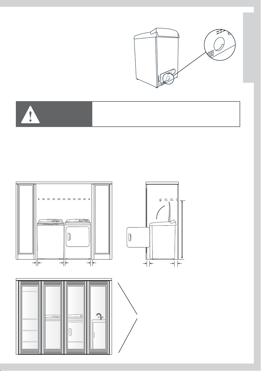
Alcove or Closet Installation
When installing a dryer in a closet/alcove it must be
WARNING
exhausted to the outdoors. No other fuel burning appliance
can be installed in the same closet or alcove.
US
CA
The total ventilation area must be a minimum of 387cm
distributed. If the closet contains both a washer and a dryer, doors must contain a minimum of
2
(120 sq. in.) of open area equally distributed. The openings must never be obstructed (a
774cm
2
(60 sq. in.) of open area equally
louvered door with the minimum air opening is acceptable). Minimum installation clearances are
required but more clearance is recommended.
minimum clearance
required
1430mm (56 /”)
25mm (1”)
25mm (1”) 25mm (1”)
min 50mm (2”) min 76mm (3”)
total ventilation area
774cm2 (120 in. sq.)
11
Location Requirements
Bathroom or Bedroom Installation
The Dryer MUST be vented to the outdoors. See EXHAUST information.
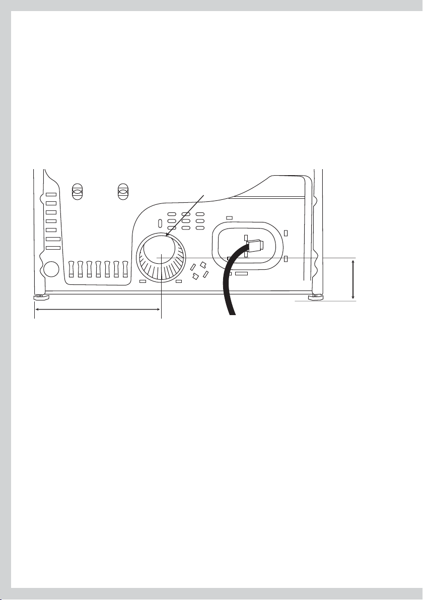
Dimensions
Exhaust Outlet Location
Exhaust outlet
298mm (11 /”)
114mm (4 /”)
Mobile or Manufactured Home Installation
Installation must comply with the current CAN/CSA Z240 MH series Mobile Home Installation
Codes or the Manufactured Home Construction & Safety Standard, title 24, part 32-80 or, when
such standard is not applicable, with American National Standard for Mobile Home, AINSI/NFPA
NO. 501B.
The dryer MUST be vented to the outdoors with the termination securely fastened to the mobile
home structure. (See EXHAUST information).
The vent MUST NOT be terminat
The vent duct material MUST BE METAL.
The vent MUST NOT be connected to any other duct, vent, or chimney.
Do not use sheet metal screws or other fastening devices which extend into the interior of the
exhaust vent.
In addition to the above, for gas dryers:
Kit 14-D346-33 MUST be used to attach the dryer securely to the structure.
Provide an opening with a free area of at least 161cm sq. (25 sq. in.) for introduction of outside air
into the dryer room.
12
ed beneath a mobile or manufactured home.
Exhausting
WARNING
Fire Hazard
The dryer must be vented to the outdoors.
Use rigid or thick wall exible metal exhaust duct.
Do not use a plastic exhaust duct.
Do not use a metal foil exhaust duct.
Failure to follow these instructions can result in death or re.
The dryer must be exhausted to the outdoors. This will prevent the build up of lint and moisture
in the room in which it is located and reduce the risk of fire.
This appliance must always be vented to the outdoors.
Only rigid or flexible metal duct shall be used for exhausting.
In Canada and in the United States, only those foil-type flexible ducts, if any, specifically identified
for use with the appliance by the manufacturer and that comply with the Outline for Clothes
Dryer Transition Duct, Subject 2158A, shall be use
In Canada and in the United States, the required exhaust duct diameter is 102 mm (4”).
Exhaust ducting products can be purchased from your local Appliance store or Hardware store.
Plastic or metal foil flexible duct can kink, sag, be punctured, reduce airflow, extend drying times
and affect dryer operation.
A minimum of 100mm (4”) thick wall flexible metal or rigid galvanized metal duct must be used.
Using ducts larger than 100mm (4”) diameter may result in more lint accumulating.
Using straight rigid metal ducting will minimize lint accumulation. Thick wall flexible metal
ducting may be used but care must be exercised to avoid sharp bends which may squash the
duct and cause blockages. Do not use plasti
Use duct tape to secure joints. Do not use screws as they collect lint.
Keep ducting as short and straight as possible. Do not exceed the maximum exhaust duct
lengths stated later in these installation instructions.
Do not exhaust the dryer into a chimney or gas vent, a wall, a ceiling, an attic, a crawl space, or
any concealed space in a building. Do not exhaust the dryer under a house or mobile home or a
porch, or into a window well or other area that will accumulate lint.
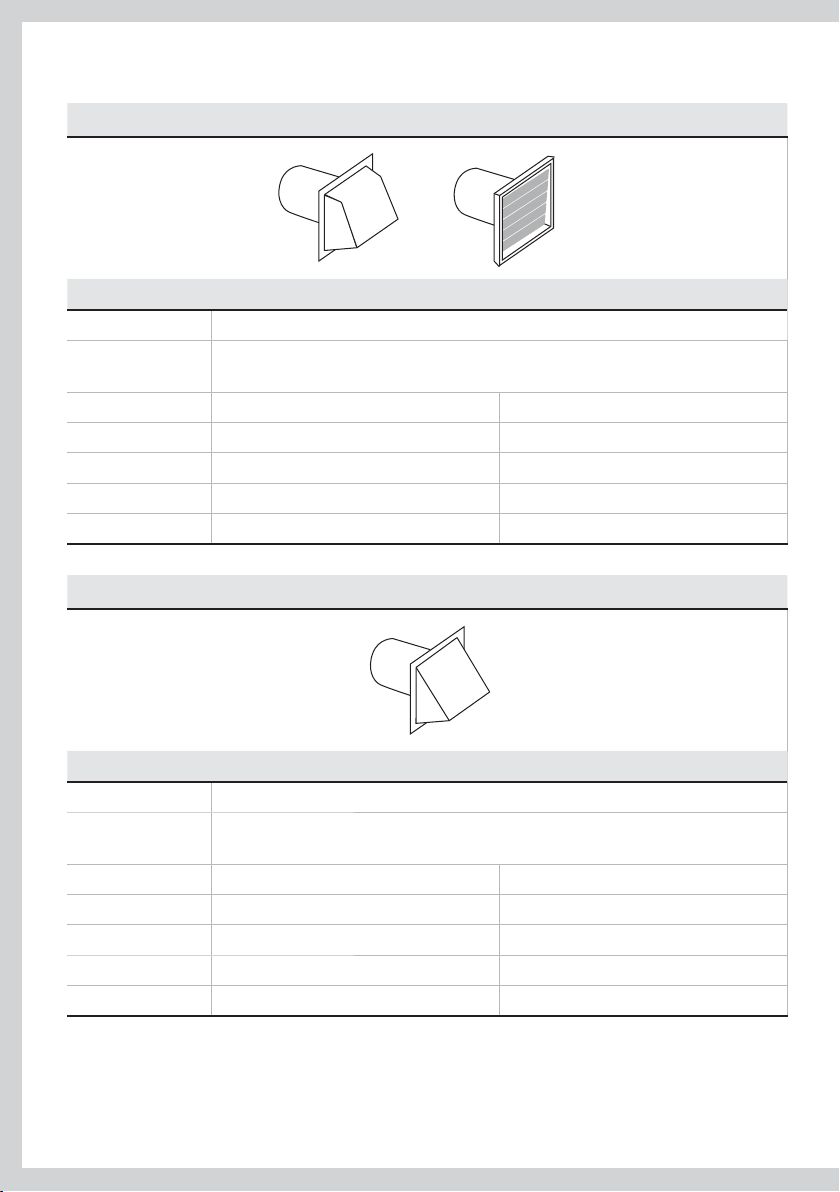
The exhaust duct should end with an exhaust hood with a
swing out damper to prevent back drafts and entry of wild
life. Never use exhaust hoods with a magnetic damper. The
hood should have at least 305mm (12 inches) clearance
een the bottom of the hood and the ground or other
betw
obstruction. The hood opening should point down. Never
install a screen over the exhaust outlet.
d.
c ducting or thin wall flexible metal ducting.
305mm (12”)
US
CA
13
Exhausting
To reduce condensation, insulate any ducting which passes through unheated areas.
Slope the duct gently downwards to the hood, to drain condensation and reduce lint build up.
Avoid sag or loops in the duct as they may collect and store water and accumulate lint.
Before using an existing exhaust duct system for a dryer ensure that:
No plastic or other potentially combustible duct or flexible metal foil ducting has been used.
The duct is not pierced, kinked or crushed.
The duct does not exceed the maximum recommended length for the new dryer.
The exhaust hood damper opens and closes freely and with sufficient movement.
Static pressure in the exhaust ducting does not exceed 250Pa (1 inch of water column), or is no
less than 0 inches of water column (i.e. negative pressure), when measured with a manometer in
the first 150mm (6”) of the duct, with the dryer running on Fluff (no heat) setting.
The exhaust duct system meets all relevant local, state, province and national codes.
All ducting should be inspected and cleaned at least once a year to remove accumulated lint.
Frequently check that the damper on the exhaust hood moves sufficiently and opens and shuts
freely.
Mobile Home Installations
A Mobile Home Installation Kit is available (see Accessories page 9 and notes page 12).
t
Determine Vent Duct Length
Different types of vent arrangements are shown below.
14
Exhausting
Choose a route that will provide the straightest and most direct path outdoors. Plan the
installation to use the fewest number of elbows and turns.
When using elbows (rigid duct) or making turns (thick wall flexible metal duct), allow as much
room as possible. With thick wall flexible metal duct bend duct gradually to avoid kinking and
avoid 90˚ turns.
US
CA
recommended
acceptable
Maximum Length of Exhaust Duct
The maximum length of the exhaust duct system depends upon:
The type of ducts (rigid or thick walled flexible metal).
The number of elbows or bends used.
Refer to the exhaust duct length chart for the maximum duct lengths you can use. Do not use 1
duct runs longer than specified in the exhaust duct length charts (refer to next page).
Exhaust duct systems longer than specified will:
Accumulate lint creating a potential fir
Shorten the life of the dryer.
Reduce performance, resulting in longer drying times and an increased energy usage.
Determine the number of elbows/bends you will need. 2
e hazard.
In the following table, find the maximum length of rigid metal duct on the same line as the 3
number of elbows/bends to be used (refer to next page).
The total length of flexible metal duct shall not exceed 2.4m (8 ft).4
15
Maximum Length of Exhaust Duct
Preferred 4” Hoods
When you have a 100mm (4”) Hood
Maximum length of 100mm (4”) diameter metal duct.
Number of 90°
elbows/bends
0 27.4m 90ft
1 18.3m 60ft
2 13.7m 45ft
3 10.7m 35ft
4 7.6m 25ft
Acceptable 2 /” Hoods
Rigid
When you have a 60mm (2 /”) Hood
Maximum length of 100mm (4”) diameter metal duct.
Number of 90°
elbows/bends
0 18.3m 60ft
1 13.7m 45ft
2 10.7m 35ft
3 7.6m 25ft
4 4.6m 15ft
For exhaust systems not covered by the exhaust duct length charts (such as multiple unit hookups, plenums, and power-assist fans), call our Customer Care Center:
TOLL FREE 1 888 9 FNP USA (1 888 9 367 872).
16
Rigid
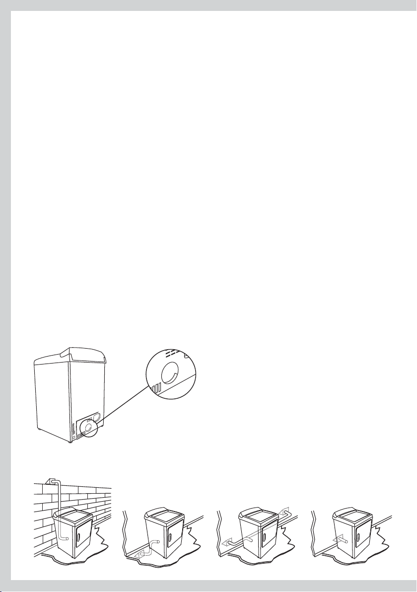
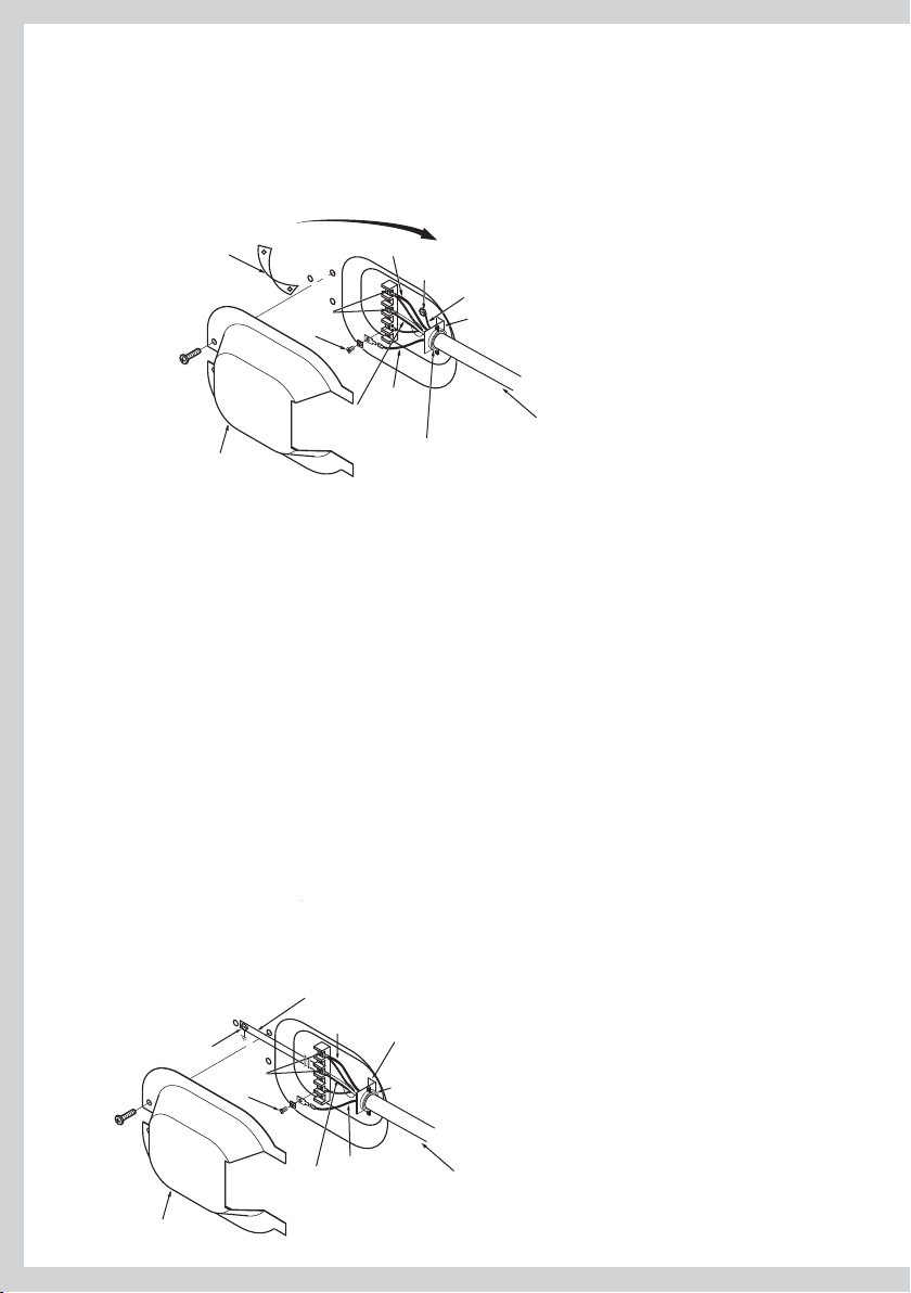
Alternative Exhaust Directions
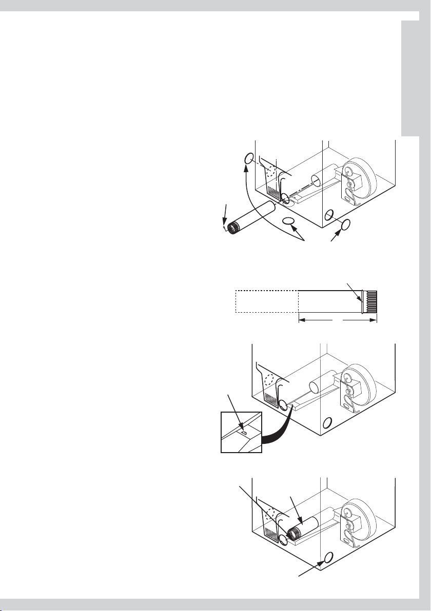
This dryer can be vented from the rear, right, left, and bottom side of the cabinet and must be
exhausted to the outdoors.
Note:
The gas dryer can not be exhausted directly through the right side of the cabinet.
Dryer Exhaust to Right , Left or Bottom of Cabinet
Detach and remove the bottom, right or
left side knockout as desired. Remove the
screw inside the dryer exhaust duct and
save. Pull the duct out of the dryer. Protect
sharp edges around the knockout and
exhaust opening with tape.
Remove
screw
and save
Remove
desired knockout
(one only)
US
CA
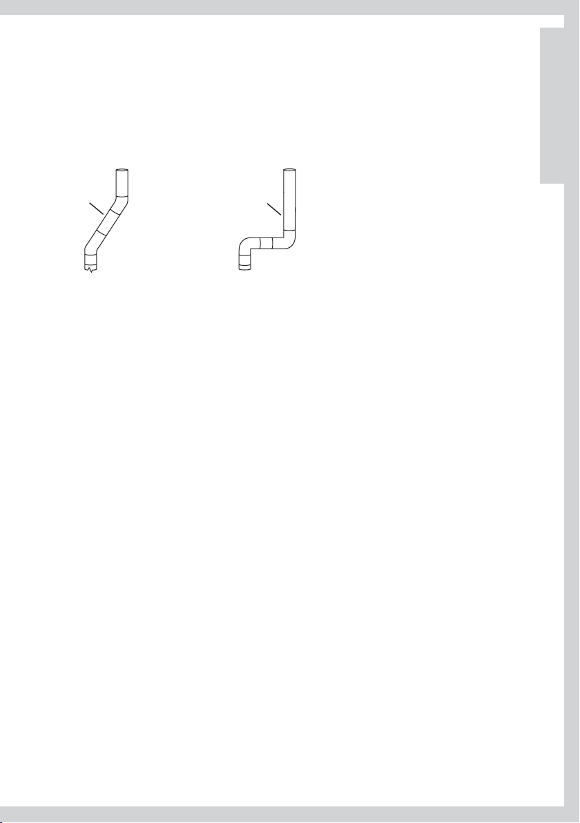
Cut the duct as shown and keep portion A.
Tab Location
Through the rear opening, locate the tab in the
ddle of the dryer base. Lift the tab to about
mi
45° using a flat blade screwdriver.
Adding New Duct
Reconnect the cut portion (A) of the duct to
the blower housing. Making sure that the
shortened duct is aligned with the tab in the
base. Use the screw saved previously to secure
the duct in place through the tab on the dryer
base.
Bend tab
up 45°
Fixing
Hole
B
Portion “A”
Right or
left side
exhaust
Fixing hole
A
9”
17
Alternative Exhaust Directions
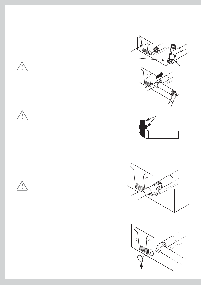
Adding Elbow and Duct for Exhaust to Right or Left Side of Cabinet
Preassemble 100mm (4”) elbow with 100mm
(4”) duct. Wrap duct tape around joint.
Insert duct assembly, elbow first, th
side opening and connect the elbow to the
dryer internal duct.
rough the
Exhaust can
be added to
left or right side
CAUTION!
Be sure not to pull or damage the electrical
wires inside the dryer when inserting the duct.
Apply duct tape as shown on the joint between
the dryer internal duct and the elbow.
CAUTION!
Internal duct joints must be secured with tape,
otherwise they may separate and cause a safety
hazard.
Adding Elbow for Exhaust through Bottom of Cabinet
Insert the elbow through the rear opening and connect it
to the dryer internal duct.
Apply duct tape on the joint between the dryer internal
duct and elbow, as shown above.
CAUTION!
Internal duct joints must be secured with tape,
otherwise they may separate and cause a safety
hazard.
Duct tape
Duct tape
Adding Cover Plate to Rear of Cabinet (Sides and Bottom Exhaust)
Connect standard metal elbows and ducts to complete
the exhaust system. Cover back opening with a plate (kit
WE1M454) available from your local service provider. Place
dryer in final location.
18
Plate (kit WE1M454)
Exhaust Venting
WARNING
Fire Hazard
Use metal exhaust duct.
Do not use a plastic exhaust duct.
Do not use thin metal foil exhaust duct.
Failure to do so can result in death or re.
Read the exhaust section (pages 13 – 18) before installing the exhaust system to determine the 1
maximum allowable exhaust duct length.
Do not use sheet metal screws when assembling ducting. Always use suitable duct tape. Never
use plastic or thin metal foil flexible exhaust material.
The exhaust outlet is located close to the center of the rear of the dryer. Make sure you join the 2
exhaust duct to the dryer with duct tape only. This will prevent lint and dust from escaping from
the dryer and exhaust system.
298mm (11 /”)
Exhaust outlet
114mm (4 /”)
US
CA
The exhaust vent can be routed up, down, left, right or straight
diagram.
out the back of the dryer. Refer to 3
19
Installation
Parts and literature are packaged inside the dryer drum.
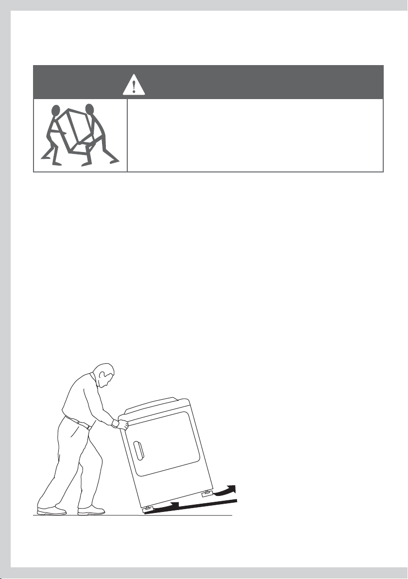
WARNING
Excess Weight Hazard
Use two or more people to move and install the dryer.
Failure to do so can result in back or other injury.
Only remove the packaging at the customer’s premises.
This will ensure the appliance arrives in pristine condition and reduces the risk of damage when
transporting to the customer’s home.
Unpacking
Make sure dryer is in a suitable location for installation.
Consider installing the dryer before the washing machine in a side by side installation, this will
allow better access to electrical and exhaust connections.
Foam Removal from Dryer Legs
Tilt the dryer sideways and remove the foam shipping pads by pulling at the sides and breaking
them away from the dr
20
yer legs. Be sure to remove all of the foam pieces around the legs.
Grounding Instructions for Gas and Electric Dryers
WARNING
Electric Shock Hazard
Make sure appliance is wired or plugged into a grounded outlet.
Do not use an adaptor.
Do not use an extension cord.
Failure to follow these instructions can result in death, re, or
electrical shock.
WARNING
Electric Shock Hazard
Check with a qualied electrician or service person if you are in
doubt as to whether the appliance is properly grounded.
Do not modify the plug if it will not t the outlet.
Have the proper outlet installed by a qualied electrician.
Failure to follow these instructions can result in death, re, or
electrical shock.
US
CA
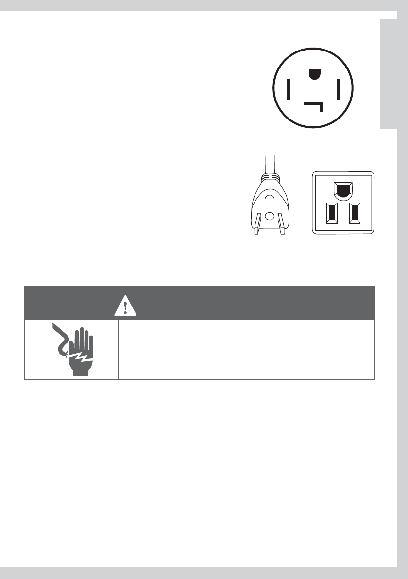
Grounding for a Cord-Connected Appliance
This appliance must be grounded. In the event of malfunction or breakdown, grounding will
reduce the risk of electric shock by providing a path of least resistance for electric current.
When this appliance is equipped with a cord having an equipment-grounding conductor and a
grounding plug, the plug must be plugged into an appropriate outlet that is properly installed
and grounded in accordance with
National Electrical Code ANSI/NFPA 70, or the Canadian Electrical Code CSA C22.1.
WARNING
Refer to pages 22 – 24 for wiring details for electric dryers, including the grounding requirements
for a direct wired appliance.
all local codes and ordinances, or in their absence, with the
Improper connection of the equipment-grounding
conductor can result in a risk of electric shock. Check with
a qualied electrician or service representative if you are in
doubt as to whether the appliance is properly grounded.
21

Electrical Requirements for Electric Models Only
WARNING
Electric Shock Hazard
Use a new UL/CSA approved 30-ampere power cord or direct wire
cable.
Use a UL approved strain relief.
Disconnect power before making electrical connections.
Connect neutral wire (white or center wire) to center terminal.
On all four wire installations remove the grounding link and
connect the ground wire to the green ground connecting screw.
Connect remaining 2 supply wires to remaining 2 terminals.
Securely tighten all electrical connections.
Failure to do so can result in death, re, or electrical shock.
Note:
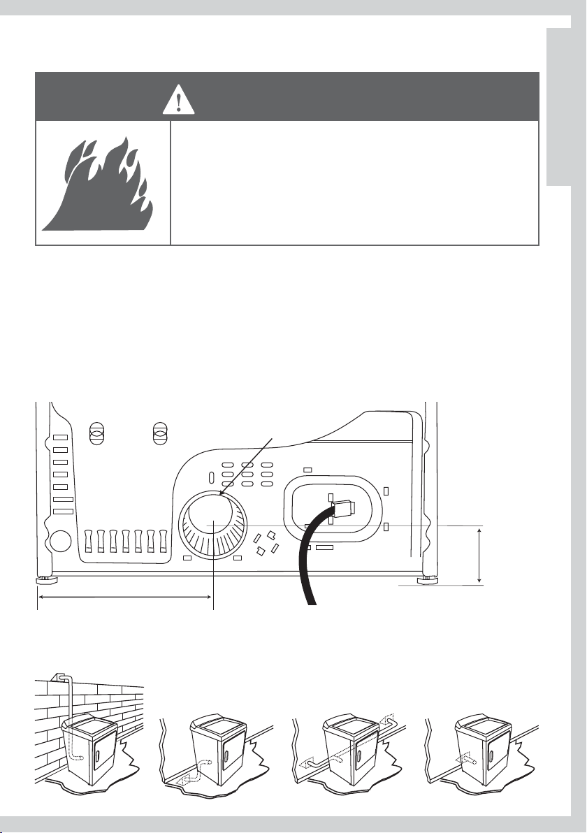
The wiring diagram is inside the control console.
The dryer must be plugged into or
connected to an individual branch circuit,
do not use an extension cord.
Ensure pr
The power supply must be 220/240V or
208V, 60 Hz approved alternating current
electrical service. The electrical service
requirements can be found on the data
label that is located on the console back.
A 30-ampere fuse or circuit breaker is
required on each of the lines.
If a power cord is used, the cord must be plugged into a 30-ampere receptacle.
The power cord is NOT provided with U.S. electric model dryer
This dryer is supplied with the cabinet grounded through the neutral on the terminal block. If
the dryer is to be installed in (1) a new branch installation, (2) a mobile home, (3) a recreational
vehicle, (4) an area where local codes do not permit grounding through the neutral conductor,
the appliance grounding link must be removed and a 4-wire power cord/cable or a separate
grounding wire must be used.
Do not reuse a power supply cord/cable from an old dryer. The power cord/cable electric supply
wiring must be retained at the dryer cabinet with a suitable UL listed strain relief.
22
oper ground exists before use.
If local codes permit, an external
ground wire (not provided),
which meets local codes, may
be added by attaching to the
green ground screw on the rear
of the dryer, and to a grounded
metal cold water pipe or other
established ground.
s.
Electric Power Supply for Gas and Electric Dryers
Power Supply for Electric Dryers: (for Canada only)
120 / 240 V or 120 / 208 V of 60 Hz sinusoidal supplied via an
individual branch circuit with a 30 ampere fuse or breaker in
each of the lines.
Connected to a 30 ampere wall receptacle as shown
The installation conforming to local codes. Do not modify the
plug to fit a different outlet
Y
G
X
W
Electric Power Supply for Gas Dryers:
120 V 60 Hz sinusoidal supplied via a circuit protected with a
15 or 20
Connected to a wall receptacle as shown
The installation conforming to local codes and/or the current
CSA C22.1 Canadian Electrical Code part 1.
ampere fuse or breaker.
Power Supply Cord Requirements for U.S.A
US
CA
WARNING
Electric Shock Hazard
Never leave the cover o of the terminal block.
Failure to do so will result in death or electric shock.
4-wire Connections (must be used for Mobile Home Installation)
Note:
Sine January 1, 1996, the National Electric Code requires that new constructions utilize a 4 wire
connection to an electric dryer.
Turn off the circuit breaker(s) (30 amp) or remove the dryer’s circuit fuse at the electrical box.1
Be sure the dryer cord is unplugged from the wall receptacle.2
Remove the power cord cover located at the lower back.3
Remove and discard ground strap. Keep the green ground screw for step 7.4
Install 5 /” UL recognized strain relief to
Connect power cord as follows: 6
A. Connect the 2 hot lines to the outer screws of the terminal block (marked L1 and L2).
B. Connect the neutral (white) line to the center of the terminal block (marked N).
power cord entry hole. Bring power cord through strain relief.
23
Power Supply Cord Requirements for U.S.A
Attach ground wire of power cord with the green ground screw (hole above strain relief bracket). 7
Tighten all terminal block screws (3) completely.
Properly secure power cord to strain relief.8
Reinstall the cover.9
Remove ground strap
and discard. Keep green
ground screw
Cover
3-Wire Connections
If required, by local code, install external ground (not provided) to grounded metal, cold water
pipe, or other established ground determined by a qualified electrician.
Turn off the circuit breaker(s) (30 amp) or remove the dryer’s circuit fuse at the electrical box.1
Be sure the dryer cord is unplugged from the wall.2
Remove the power cord cov
Install 4 /” UL recognized strain relief to power cord entry hole. Bring power cord through strain
relief.
Connect power cord as follows:5
A. Connect the 2 hot lines to the outer screws of the terminal block (marked L1 and L2).
B. Connect the neutral (white) line to the center of the terminal block (marked N).
Be sure ground strap is connected to neutral (center) terminal of block and to green ground 6
screw on cabinet rear. Tighten all terminal block screws (3) completely.
Properly secure power cord to strain relief.7
Reinstall the cover.8
Green ground screw
Screws
(3)
Neutral
(white)
Cover
24
Screws
(3)
Neutral
(white)
er located at the lower back.3
Ground strap
Hot wire
L1
L2
Hot wire
Hot wire
1L
N
2L
Hot wire
/”, UL recognized
strain relief
Strain relief bracket
/”, UL recognized
strain relief
Relocate green
ground screw here
Green or yellow wire
Strain relief bracket
4 #10 AWG minimum copper conductors
or 120/240V 30A power supply cord kit
marked for use with dryers & provided
with closed loop or spade terminals with
upturned ends (not supplied)
3 #10 AWG minimum copper
conductors or 120/240V 30A power
supply cord kit marked for use with
dryers & provided with closed loop
or spade terminals with upturned
ends (not supplied)
Gas Requirements (Gas Models Only)
The installation must conform with Local Codes, or in the absence of Local Codes, to the National
Fuel Gas Code ANSI Z223.1/NFPA 54 or the Canadian Natural Gas and Propane Installation Code,
CSA B149.1.
WARNING
Explosion Hazard
Installations must be performed by a qualied or licensed
contractor, plumber, or gastter qualied or licensed by the state,
province, or region where this appliance is being installed.
Use a new AGA or CSA approved gas supply line.
Install a shut-o valve in an accessible place.
Only use a gas shut-o valve approved for use within the state,
province, or region where this appliance is being installed.
Securely tighten all gas connections.
Failure to follow these instructions can result in death, explosion,
or re.
Gas Type
Your dryer must have the correct burner for the type of gas in your home. Burner information is
located on the rating plate located on the front of the dryer behind the door. If this information
does not agree with the type of gas available in your home, contact your local
supplier or service center.
Fisher & Paykel
US
CA
Natural Gas
This dryer is supplied ready for use with Natural Gas.
It is design certified by CSA International for LP (Propane or Butane) Gases with the appropriate
conversion.
LP Gas Conversion
If the dryer is to be operated on LP (Liquid Propane or Butane) Gas, the dryer must be converted.
To do so, use only the approved Fisher & Paykel conversion kit listed in Accessories on page 9. Do
not use with a different gas without consulting the serving gas supplier.
The dryer must be converted for safe and proper performance by qualified service or installation
personnel.
Conversion kits for Natural and LP Gas are available from your loc
Accessories page 9). If other conversions are required, check with your local gas utility for specific
information concerning conversion requirements.
al Fisher & Paykel Dealer (see
25
Connecting Gas to Your Dryer (Gas Models Only)
Use compound or thread tape appropriate to the gas type that is to be used (Natural or LP Gas),
on the male threads of all non-flared connections.
Never use an open flame to test for gas leaks.
This dryer will operate satisfactorily up to altitudes of 2000m (6500ft) above sea level at the
BTU rating indicated on the model/serial plate. Burner input adjustments may be required if
operating above this elevation.
The dryer must be isolated from the gas supply piping system by closing the supply shut-off
valve during any pressure testing of the gas supply piping system.
Gas Ignition
This dryer has an automatic ignition system to ignite the burner. There is no pilot flame burning
in this dryer.
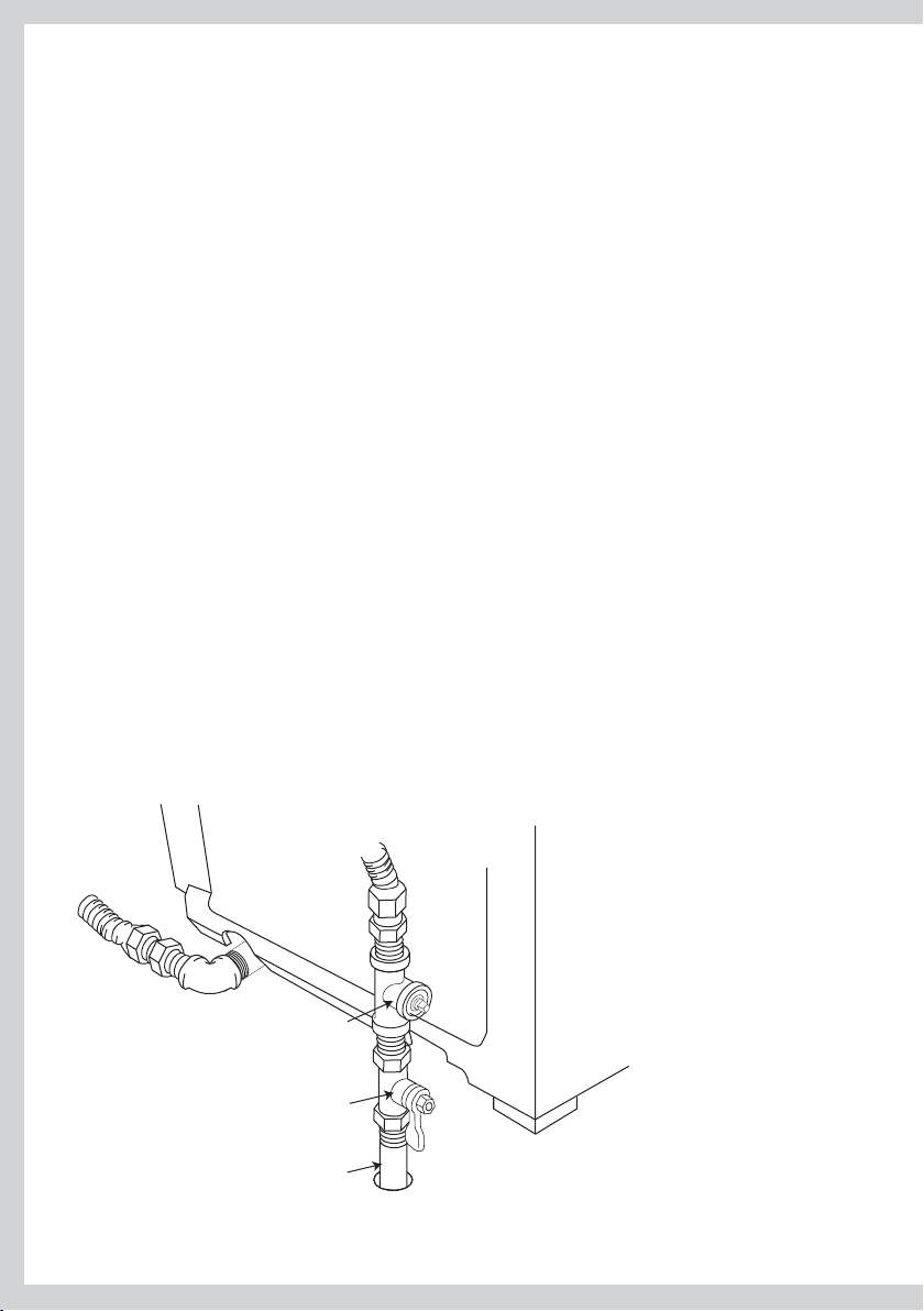
Connecting to the Gas Supply
The gas supply line should be 12.7mm (1 /“).
An individual manual shut-off valve must be installed on the gas supply line within 1.8m (6ft) of 2
the dryer, in accordance with the National Fuel Gas Code ANSI Z223.1/NFPA 54 for the United
States or in accordance with the B149.1 Natural Gas and Propane Installation Code for Canada.
An 3 / inch NPT plugged tapping must be installed to allow the gas inlet pressure to be checked.
It must be accessible for test gauge connection and immediately upstream of the gas connection
to the dryer.
26
/” NPT plugged tapping
Gas shut-off valve
/” NPT gas supply line
Connecting Gas to Your Dryer (Gas Models Only)
A listed connector in compliance with ANSI Z21.24/CSA6.10 must be used to connect the dryer to 4
the gas supply.
If flexible tubing is used, an elbow should be installed on the pipe at the back of the dryer for 5
the flexible tube to be connected to. This will minimize damage to the tube when the dryer is
moved back. Use a flexible tubing connection kit that has designed for use on a clothes dryer.
This kit should have the unions necessary to join to the ends of the tubing. Be sure to follow all
instructions supplied with the kit.
Copper tubing should not be used for Natural Gas and if used for LP Gas, it must be LP Gas 6
compatible.
Disconnect and discard old flexible tubing.7
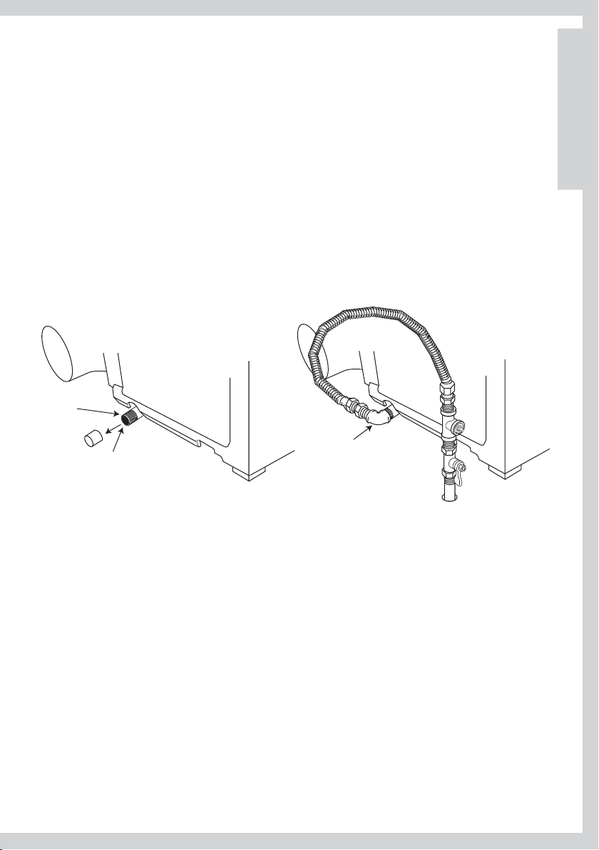
The
gas pipe that comes out of the rear of your dryer has on it a 8 /” NPT male thread. Remove
the protective cap and apply sealing compound or tape to the thread. Thread sealant should be
appropriate for the type of gas to be used.
Apply thread
sealant
US
CA
Remove cap
/” NPT pipe thread
Elbow required
for flexible tubing
Completing the Connection
Use wrenches to tighten all joints but do not over tighten.1
Open the gas supply valve and check all joints by brushing on a non-corrosive leak-detecting 2
solution. Bubbling will indicate a leak. If any leaks are found, close the valve immediately and
correct the leaks. Retest with repeat until no leaks are found.
27
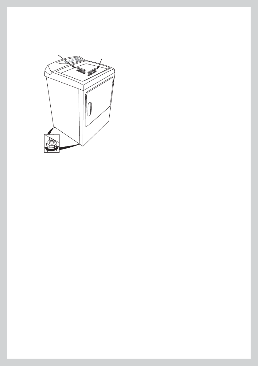
Level Machine
Check the dryer is level, and make necessary adjustments.
Adjust all 4 leveling legs to match washer height. Dryer MUST BE LEVEL and rest firmly on all 4
leveling legs.
Level front-to-back
4 leveling legs
Level side-to-side
Final Installation Check List
Check that:
No plastic or flexible metal foil is used in the exhaust ducting.
Exhaust is rigid ducting or thick wall flexible metal ducting.
All joints in the ducting are made with duct tape. It must not be connected with screws or other
fastening devices which extend into the inside of the duct.
Ducting is clean and is connected to the dryer.
Dryer is level.
Additionally for Electric Dryer Models Only, Check:
Dryer is plugged or directly wired into an approved fitting and is properly grounded.
Dryer starts, heats, cools and shuts off.
Additionally for Gas Dryer Models Only, Check:
Dryer is plugged into an approved fitting and is properly grounded.
All fittings in the gas line are tested for leaks.
Exhaust temperature increases, to confirm ignition has occurred.
– If ignition does not occur initially, it may be due to air in the gas line or low voltage power supply.
– The gas regulator valve may fail to open if the power supply falls below 105 Volts.
28
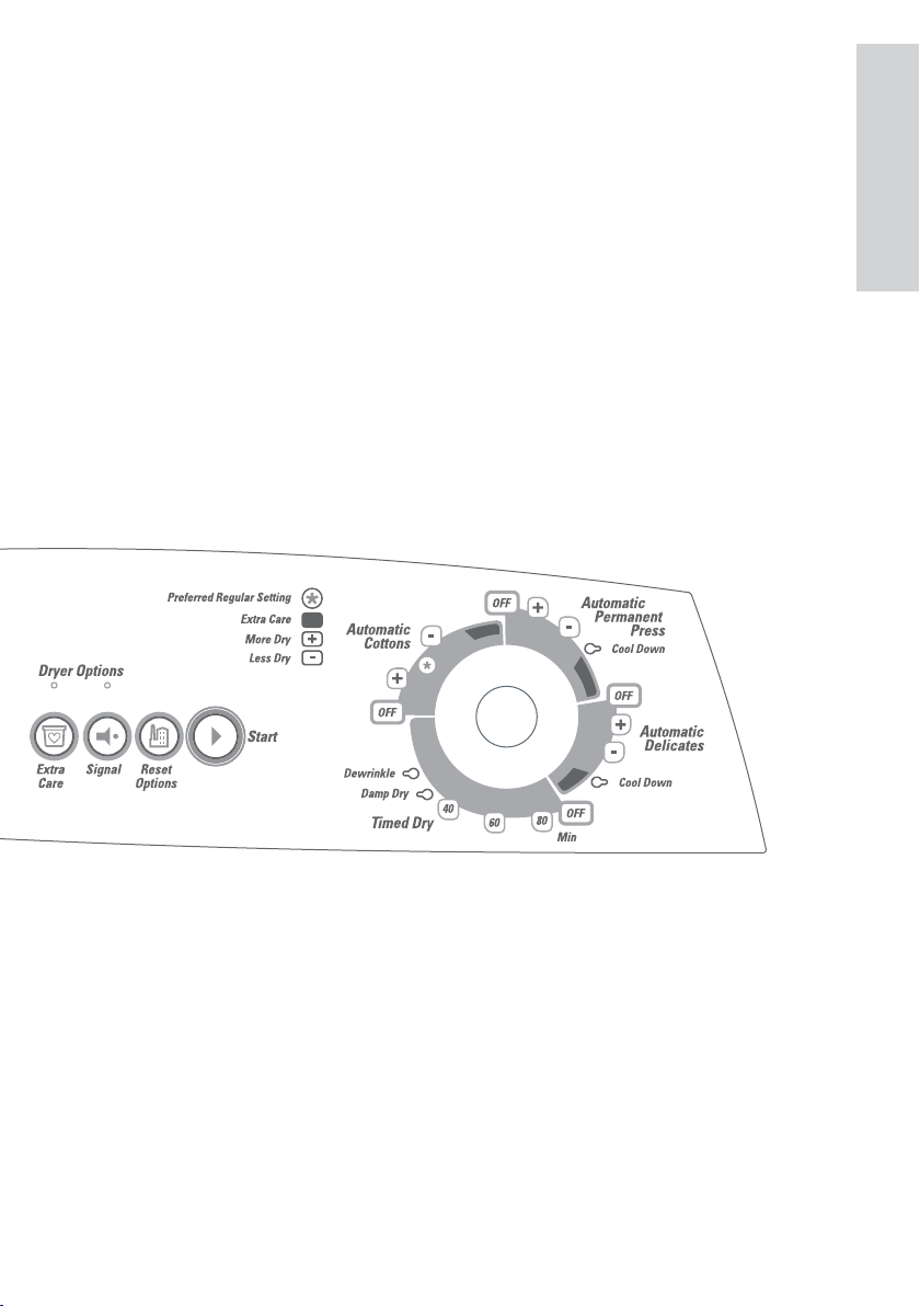
Features
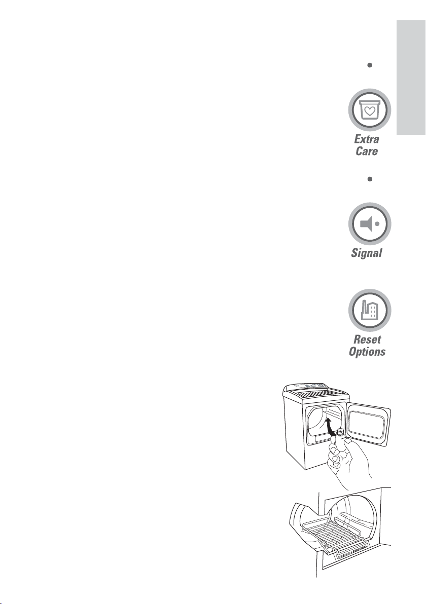
Extra Care
Use this option to minimize the wrinkles in clothes. This option provides
approximately 15 minutes of no-heat tumbling after the clothes are dry.
This option can only be used with the Automatic cycles.
Hint: If the Signal option is selected, the Signal will sound at the end of the drying
time and will sound several times during the Extra Care cycle. This will remind you
that the cycle is complete.
Signal
This signal will sound just before the end of the cycle to remind you to remove the
clothes.
If you selected the Extra Care option a signal will sound a the end of the drying
time and will sound several times during the Extra Care cycle.
This will remind y
clothes.
Note:
Remove garments promptly at the sound of the signal. Place clothes on hangers
so wrinkles won’t set in.
Use the Signal especially when drying fabrics like polyester
press. These fabrics should be removed promptly so wrinkles won’t set in.
ou that the dry cycle is complete and you should remove your
knits and permanent
US
CA
Reset Options
Selecting Reset Options cancels all options that have been selected.
Drum Lamp
A handy light inside the dryer to help make unloading easier.
Drying Rack (Optional on some models)
A handy drying rack may be used for drying articles such as stuffed
toys, pillows or washable sweaters.
Hook the rack over the lint filter so the rack extends into the dryer
drum.
Note:
The drying rack must be used with the Timed cycle. Do not use this
drying rack when there are other clothes in the dryer.
29
Operating Instructions Control Panel
Automatic Drying Cycles
(Cycle automatically senses dryness)
There are two automatic dryness levels:
These two settings dry your clothes to different degrees depending on the level of dryness you
would like.
Automatic Permanent Press – For synthetic blends. Select More Dry (+) for heavier fabrics,
Less Dry (–) for light fabrics.
Automatic Permanent Press – For lingerie and special care fabrics. Select More Dry (+) for
larger fabrics,
Automatic Cottons – For cottons and most linens. For most loads select the preferred Regular
Setting marked with an *. Set towards
fabrics.
Less Dry (–) for smaller fabrics.
More Dry (+) and Less Dry (–).
More Dry (+) for heavier fabrics, Less Dry (–) for lighter
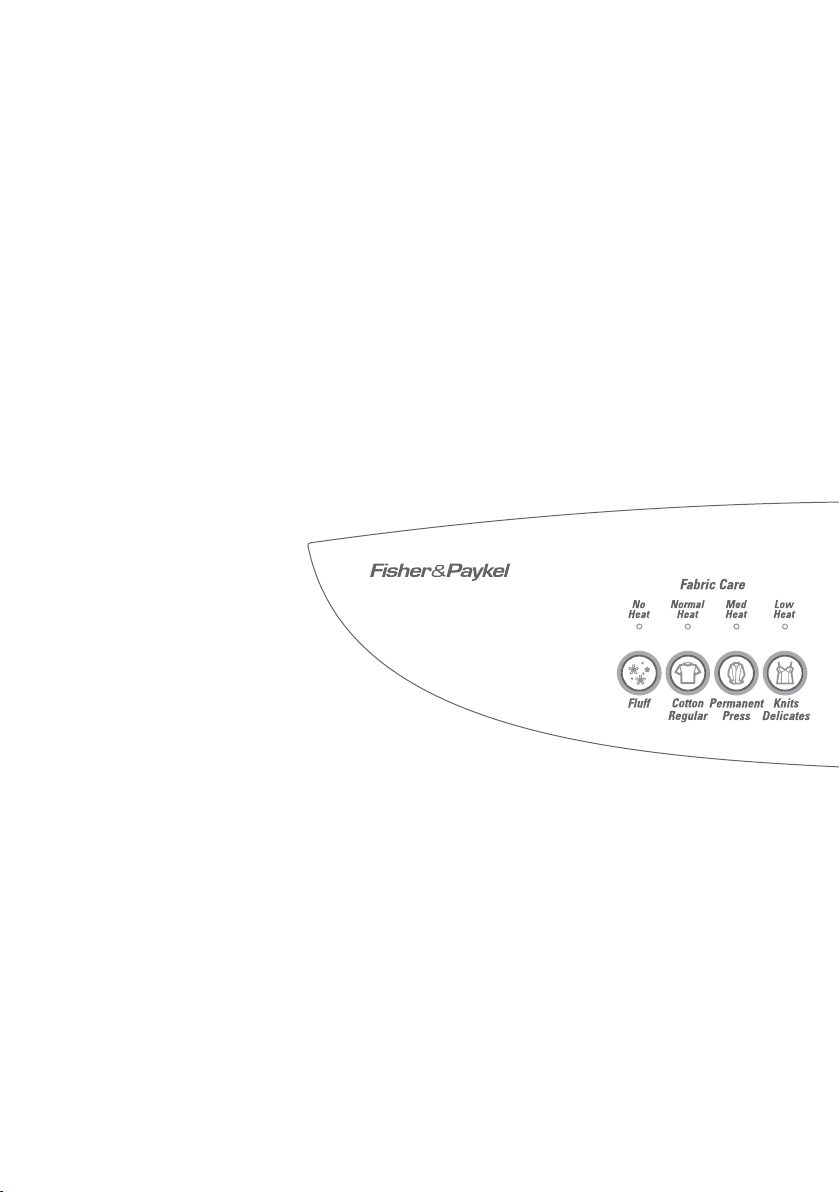
Fabric Care Settings
FLUFF – For items requiring drying without heat. Perfect for airing clothes or to freshen up
garments that have been packed in a suitcase or drawer.
COTTON REGULAR – For drying general cottons such as sheets, sweats and knits. This cycle uses
high heat to dry clothes quickly. Suitable for garments labeled “tumble dry”.
PERMANENT PRESS – For drying lightweight fabrics. A medium heat is used to reduce wrinkles.
Ideal for lightweight cottons, casuals and items labelled “tumble dry with a medium heat”
cycle automatically selects the
KNITS DELICATES – For heat sensitive items, this cycle uses a low heat. Use this setting when
care labels recommend low heat settings or for garments with a synthetic fiber content, where
overheating could cause damage to fibers.
DEWRINKLE option to reduce wrinkles.
. This
30
Operating Instructions Control Panel
Timed Dry Cycles
(Cycles run for a selected time)
The dryer has three timed cycles. These cycles have set drying times of either 40, 60 or 80
minutes and include a
the specified period of time.
Timed Dry – Set the Cycle Selector at the desired drying time.
Damp Dry – To leave items partially dry set the Cycle Selector on Damp Dry setting.
Dewrinkle – For removing wrinkles from items that are clean and dry or that are slightly damp.
Set the Cycle Selector on to Dewrinkle setting.
Note:
Drying times will vary according to the type of heat used (Electrical
types of fabrics, wetness of clothes and condition of exhaust ducts.
DAMP DRY and DEWRINKLE function. If selected, your dryer will dry for
or Natural Gas), size of load,
US
CA
31

Reversing the Door
Tools Need:
Standard #2 Phillips screwdriver
Tape-tipped putty knife
Needle-nosed pliers
Open the door and remove the filler plugs opposite the hinges.1
With the door completely open, remove the bottom screw 2
from each hinge on the dryer face.
Insert these screws about half way into the top holes, for 3
each hinge, on the opposite side (where you removed the
filler plugs). Apply firm pressure to get the screw started in
untapped holes.
Loosen the top screw from each hinge on the dryer face half 4
way.
With one hand holding the top of the door and the other hand 5
holding the bottom, remove the door from the dryer by lifting
it up and out.
Rotate the door 180°.
opening by moving the door in and down until the top hinge
and the bottom hinge are resting on the two top screws
inserted in step 3.
Remove the remaining screws from the side of the opening 7
from which the door was removed. With these screws secure
each hinge at the bottom.
Tighten the two top screws of each hinge.8
Reinsert the plastic plugs on the side from which the door was 9
removed.
32
Insert it on the opposite side of the 6

Quick Start
WARNING
US
CA
To reduce the risk of re, electric shock, or injury to persons,
read the IMPORTANT SAFETY INSTRUCTIONS before
operating this appliance.
WARNING
Fire Hazard
Only dry fabrics that have been washed with water.
Do not use heat to dry articles containing foam rubber or similarly
textured rubber-like materials. Dry on the Flu cycle.
A clothes dryer produces combustible lint and must be exhausted
outdoors. Take care to prevent the accumulation of lint around the
exhaust opening and in the surrounding area.
Failure to follow these instructions can result in death or personal
injury.
WARNING
Explosion Hazard
Keep ammable materials and vapors, such as gasoline, away from
dryer.
No washer can completely remove oil.
Do not dry anything that has ever had gasoline, oil or anything
ammable on it (including cooking oils).
Failure to follow these instructions can result in death or personal
injury.
33

Using Your Dryer
Check the care labels inside the garments to determine whether the garment manufacturer
recommends tumble drying (see care label section).
1. Sorting
It is best that you sort your garments before placing them into the dryer. Sort into loads of similar
types, and loads that take similar times to dry.
Heavier items (e.g. towels, t-shirts and flannel sheets) are best dried separately from lightweight
items (e.g. synthetics, poly-cotton sheets and shirts). This prevents the possibility of some items
becoming over-dried whilst others are still damp. It will also help to extend the life of your
clothing and linen.
Drying your clothes as soon as the was
the chance of dye transfer from colored items to white items.
We recommend that articles of clothing with screen-printing are turned inside out to ensure the
screen-printing does not stick to the drum. Garments with hooks or zippers need to be fastened
and where possible turned inside out. Place undergarments in a net bag to provide protection
from other items in the load.
Use a drying rack to dry wool garments (available as an optional accessory).
2. Loading
Garments need to be loaded properly to reduce the likelihood of them wrinkling and to ensure
the load is dried evenly. Make sure there is ample room for the garments to tumble freely while
Load in terms of the space the garments take up when dry, rather than when they are
drying.
wet.
The general rule is one wash load = one dryer load.
It is a good idea to dry ‘permanent press’ type garments together in a separate cycle with the
EXTRA CARE option turned on. This will help reduce wrinkles and the need for ironing.
her has finished will decrease the chance of wrinkles and
3. Clean the Lint Filter
Clean the lint filter each time you use the dryer, before or after each load.
It is important that you run your dryer with the lint lter in place at all times.
34

Using Your Dryer
4. Selecting a Cycle
Your dryer has a number of FABRIC CARE CYCLES that can be used to dry different types of
garments:
Select an automatic or timed cycle. See the below Cycle Descriptions.
Select a drying cycle that matches the type of load you are drying. Different fabrics have different
drying requirements, so it is important to choose the cycle that best describes the load. If your
load contains mainly delicate items it is best you select the
Always follow manufacturer’s care label instructions when drying.
If you are unsure of the temperature to select for a load, it’s best to select a lower heat rather than
a higher heat, e.g. the
KNITS DELICATES or PERMANENT PRESS cycle instead of the COTTON
REGULAR cycle.
FLUFF – For items requiring drying without heat. Perfect for airing clothes or to freshen up
garments that have been packed in a suitcase or drawer.
COTTON REGULAR – For drying general cottons such as sheets, sweats and knits. This cycle uses
a high heat to dry clothes quickly. Suitable for garments labelled “tumble dry”.
PERMANENT PRESS – For drying lightweight fabrics. A medium heat is used to reduce wrinkles.
Ideal for lightweight cottons, casuals and items labelled “tumble dry with a medium heat”. This
cycle automatically selects the
DEWRINKLE option to reduce wrinkles.
KNITS DELICATES – For heat sensitive items, this cycle uses a low heat. Use this setting when
care labels recommend low heat settings or for garments with a synthetic fiber content, where
overheating could cause damage to fibers.
KNITS DELICATES cycle.
US
CA
Extra Care
Minimizes the likelihood of wrinkles forming in clothes if you are not able to
unload the dryer straight away.
35

Using Your Dryer
5. Selecting the Dryness Level
The desired dryness level can be altered. There are two dryness levels to choose between:
MORE DRY (+)
LESS DRY (–)
Refer to page 30 for Dryness Level descriptions.
At the end of the cycle, if the clothes are still damp or are too dry, next time just adjust the
dryness level on the timer to meet your personal preferences.
6. Selecting the Drying Process
There are two ways in which your dryer is able to dry clothes; by using AUTOMATIC DRYING
CYCLES or by using TIMED DRY.
AUTOMATIC DRYING
When AUTOMATIC DRYING is selected the dryer automatically senses the dryness level of the
load and turns off when the clothes ar
content of the load using metal sensing bars and together with a temperature sensor determine
when the clothes have reached the selected dryness level (Refer to above - Selecting the Dryness
Level).
For optimum clothes care, match the cycle to the load.
best results and leads to lower energy costs than
As Automatic Drying Cycles rely on items of the load contacting sensors it will not work when the
Drying Rack accessory is used.
e dry. The dryer’s internal computer measures the moisture
AUTOMATIC DRYING often provides the
TIMED DRY.
TIMED DRY
There are three timed cycles. You can choose between 40, 60 and 80 minutes. A COOL DOWN
period of 10 minutes is included in the th
To select a timed cycle, set the Cycle Selector at the desired drying time you want your dryer to
run for. Throughout the cycle, the Cycle Selector will rotate towards the end of the cycle.
ree cycles.
During TIMED DRY, the dryer does not sense when the clothes are dry. This may cause
over-drying. We recommend that you dry your clothes for a slightly shorter time than
you think they need, or check on them regularly (to avoid over-drying).
36

Using Your Dryer
7. Beginning Drying Cycle
Once you have chosen all your desired settings, close the dryer door and press START (located on
the right-hand side of the control panel).
Opening the door during the operation will stop the dryer.
To restart the dryer, close the door and select
8. Stopping Your Dryer
Your dryer can be stopped during any stage of the drying process, to allow you to check on your
load or add/remove clothes.
To do this, open the dryer door. There will be a slight delay as the drum slows down and stops.
Note:
If the cycle is interrupted before it progresses into
rt your dryer again, press
To sta
START.
9. Changing Cycles During Operation
If you wish to change the drying cycle you have chosen after the machine has already begun
drying, press your new cycle selection on the control panel.
START to complete the cycle.
COOL DOWN, parts of the drum may be hot.
US
CA
10. Fabric Softener Sheets
If you want to use fabric softener sheets, you must ensure that they are labelled “dryer safe”.
Always follow the instructions on the packaging. Do not place them in a dryer with warm clothes
as there is a chance the fabric softener may stain clothes. Only use a softener sheet once, then
discard it.
11. Beeps
At the end of the cycle, the dryer will beep to let you know that the load is finished. The drum
will automatically come to rest, allowing you to open the door and remove your load.
37
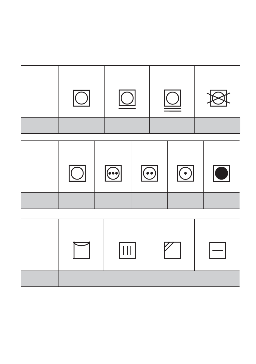
Care Labels
Below is a selection of care label symbols that garment manufacturers use to show how their
garments should be dried. We’ve converted these symbols into the cycles and heat settings that
we recommend you use in the dryer. By following our recommendations, you can ensure that
your clothes will retain their appearance over time.
Tumble Dry
Symbols
Cycle We
Recommend
Tumble Dry
Symbols
Cycle We
Recommend
Additional
Drying
Instructions
Normal Permanent Press Delicate Do not
Tumble Dry
COTTON
REGULAR
Any Heat High Medium Low No Heat
Any Cycle
Hang to Dry Drip Dry Dry in Shade Dry Flat
PERMANENT
PRESS
COTTON
REGULAR
DELICATES
PERMANENT
PRESS
KNITS
KNITS
DELICATES
FLUFF with
Drying Rack
FLUFF
38
Cycle We
Recommend
Do not place articles with these
symbols in the dryer
Use drying rack

Drying Special Items
There are some articles that need to be dried in a special way. Before you dry any item that is not
described in the dryer’s cycles (page 35), refer to the table below. Always remember to follow the
manufacturer’s instructions.
Item Special Instructions
Pillows
Blankets
Plastic
Foam rubber
Rubber-backed products
Check the care label – Can the pillow be dried in the dryer?
Do not dry foam rubber pillows.
It is important that before placing a pillow in the dryer you
check for weak seams where feathers or fillings could escape.
You can dry one average sized pillow at a time.
Choose the
It’s best to place the pillow on a drying rack to avoid any chance
of the filling escaping, balling or clumping.
Check the pillow at regular intervals.
If you are using a drying rack, you will need to turn the pillow at
regular intervals to ensure even drying.
Note: It is important to completely dry the pillow to prevent
mildew from forming.
Check the care label – Can the blanket be dried in the dryer?
Include 4-5 medium sized towels along with the blanket for
cushioning. This will help stop shrinkage from over tumbling.
Choose the
drying time.
On completion, remove the blanket, shake and, if needed,
stretch the blanket back to its original shape. Place it back in the
dryer and repeat until the blanket is dry.
Note: It is important to completely dry the blanket to prevent
mildew from forming.
Do not dry products containing foam rubber, plastic or rubber
on any cycle other than
Drying these types of garments on any cy
FIRE RISK.
is a
KNITS DELICATES and set 20 minutes drying time.
KNITS DELICATES cycle and set 20 - 25 minutes
FLUFF.
cle other than
FLUFF
US
CA
39

Drying Special Items
Item Special Instructions
Extra large items
(including bedspreads
and comforters)
Sports Shoes
“In Dryer” Dry-Cleaning
Products
Check the care label – Can item be dried in the dryer?
Use a low heat setting. We recommend
AUTOMATIC DRYING.
Select the
It is best to check the item halfway though the cycle to ensure
even drying.
If the item contains feathers add a heavy item (e.g. a wet towel
tied in a knot) to the load to help fluff the comforter.
Place the shoes on the drying rack.
Use
MORE DRY Dryness Level.
TIMED DRY, set for 20 minutes, select the KNITS
DELICATES cycle.
Check the shoes at regular intervals.
At the end of the cycle check if the shoes are dry. If the
damp set the dryer for a further 20 minutes.
Ensure the dry-cleaning product is recommended for use in a
domestic dryer.
Follow the manufacturers instructions for how to prepare the
load.
Set the dryer to the
medium heat. Select
At the end of the cycle remove the dry-cleaning product from
the machine and continue to follow the dry-cleaning product’s
instructions.
KNITS DELICATES and
y are still
PERMANENT PRESS cycle, this cycle uses a
TIMED DRY for 40 minutes.
Drying Times
Drying times can be affected by a number of factors including:
The cycle chosen
Load size
Size of the items
Type of fabric
Load wetness
Location of the dryer
Venting method
Heat used (electric, natural gas or LP gas)
Condition of exhaust ducts
40

Other Features
Drying Rack
A drying rack Kit Part No WE1M396 is available as an optional accessory. This rack helps to dry
items such as sports shoes, sweaters, hats, stuffed toys and pillows – all those delicate items that
are best dried without tumbling. Contact your Fisher & Paykel Dealer.
Always use
KNITS DELICATES or PERMANENT PRESS (see Selecting the Cycle page 35).
Do not use the
the drying rack and cannot determine when articles are dry. When placing items on the drying
rack make sure they do not hang over the edge of the drying rack.
It is important to check articles throughout the cycle to avoid over-drying.
You must not tumble other clothes while you are drying items on the drying rack.
Drum Lamp (Optional on some models)
Before replacing the light bulb, be sure to unplug the dryer power cord or disconnect the dryer at
the household distribution panel by removing the fuse or switching off the circuit breaker. Reach
above the dryer opening from inside the drum. Remove the bulb and replace with the same size
bulb.
TIMED DRY when using the drying rack and a cycle with low temperatures, e.g.
AUTOMATIC DRYING option, as the machine is unable to sense articles placed on
US
CA
41

Cleaning
Clean your dryer with a soft damp cloth and wipe dry. Do not use scouring cleaners as they can
damage the paint and plastic surfaces.
Interior
The drum is rust-resistant. However, colored fabrics which lose color or bleed in the washer may
cause discoloration of the dryer drum. We recommend that the dryer drum be cleaned with a
cloth using a detergent and water paste or a mild abrasive, such as Soft Scrub TM. Complete
cleaning by thoroughly wiping the drum with a moist cloth. Then tumble-dry several wet rags or
old towels for 20 to 30 minutes before using the dryer normally.
Exterior
Wipe off any spills or washing compounds. Wipe or dust with a damp cloth. Try not to strike the
with sharp objects. Dryer control panel and finishes may be damaged by some laundry
surface
pretreatment soil and stain remover products if such products are sprayed on or have direct
contact with the dryer.
Pre-Treatment Sprays
Do not use pre-treatment sprays or liquids on or near your dryer as they can damage your
machine’s control panel as well as any of its plastic parts. Damage to your dryer caused by pretreatment products will not be covered by your warranty.
Stains
If stains appear inside the drum of your machine, mix a detergent and water paste (or use a nonflammable liquid cleaner) and wipe over the stain with a soft cloth. Then tumble old towels for
minutes on the
20 – 40
FLUFF cycle to remove all traces of the cleaner.
Lint Filter
The lint filter will need to be cleaned before each time you use
the dryer. It is easier to remove the lint when your fingers are
moistened. A lint filter that is clean ensures your clothes will remain
lint-free and your dryer will operate at maximum efficiency.
Regularly inspect the outdoor exhaust opening. Remove any
accumulated lint from this area and any surrounding areas.
Storage
To store your dryer for a short period of time, disconnect the power supply and clean the lint filter.
42

Cleaning
Exhaust Duct
Inspect and clean the dryer exhaust ducting at least once a year
to prevent clogging. A partially clogged exhaust can lengthen
the drying time.
To clean the exhaust duct follow these steps:
Turn off electrical supply by disconnecting the plug from the 1
wall socket.
Disconnect exhaust duct from the dryer.2
Vacuum the exhaust duct with hose attachment or attach a rag 3
to a pole or drain cleaning wire and clean duct.
Exhaust Hood
Make sure the inside flaps of the exhaust hood move freely (you
may want to check with a mirror).
Make sure inside flaps are fully open when dryer is operating.
Make sure there is not wild life (birds, insects, etc.) nesting
inside the exhaust duct or hood.
Venting
For best drying performance, the dryer needs to be properly vented.
To keep your dryer operating at peak performance, be sure to have a technician vacuum the lint
from the machine every three years.
US
CA
Carefully follow the details on Exhausting
in the INSTALLATION INSTRUCTIONS.
Use only rigid metal or flexible metal 100mm
(4”) diameter ductwork inside the dryer cabinet
or for exhausting to the outside.
Use the shortest length possible.
Do not crush or collapse.
Avoid resting the duct on sharp objects.
Do not use plastic or other combustible
ductwork.
Venting must conform to local building
codes.
Correct Venting
Incorrect Venting
43

Trouble Shooting
If there is a problem with your appliance, please check the following points before contacting
your local Fisher & Paykel Appliances Authorized Service Centre Dealer or Customer Care Centre.
Problem Possible causes What to do
Dryer Doesn’t
Start
Dryer Doesn’t
Heat
Dryer Shakes or
Makes Excessive
Noise
Greasy Spots on
Clothes
Lint on Clothes
Static Occurs
Dryer is unplugged Make sure the dryer plug is pushed
completely into the outlet.
Fuse is blown/circuit breaker is
tripped
Fuse is blown/circuit breaker is
tripped, the dryer may tumble
but not heat
Gas service is off Make sure gas shutoff at dryer and main
Some shaking/noise is normal.
Dryer may be sitting unevenly
Improper use of fabric softener Follow directions on fabric softener
Drying dirty items with clean
ones
Clothes were not completely
clean
Lint filter is full Clean lint screen before each load.
Improper sorting Sort lint producers (like chenille) from
Static electricity can attract lint See suggestions in this section under
Overloading Separate large loads into smaller ones.
Paper, tissue, etc. left in pockets Empty all pockets before laundering
Overdrying Try a fabric softener.
No fabric softener was used Try a fabric softener.
Synthetics, permanent press
and blends can cause static.
Check the house fuse/circuit breaker
box and replace fuse or reset breaker.
Note: Most electric dryers use two
breakers.
Check the house fuse/circuit breaker
box and replace fuse or reset breaker.
shutoff are fully open.
Move the dryer to a flat place on the
floor, or adjust feet as necessary until
even.
package.
Use your dryer to dry only clean items.
Dirty items can stain clean items and
the dryer.
Sometimes stains which cannot be seen
when the clothes are wet “appear” after
drying. Use proper washing procedures
before drying.
lint collectors (like corduroy).
STATIC.
clothes.
Adjust controls for less drying.
Try a fabric softener.
44

Trouble Shooting
Problem Possible causes What to do
Clothes Take
Too Long to Dry
Clothes are
Wrinkled
Clothes Shrink
Improper sorting Separate heavy items from light-weight
items (generally, a well-sorted washer
load is a well-sorted dryer load).
Large loads of heavy fabrics
(like beach towels)
Controls improperly set Match control settings to the load you
Lint filter is full Clean lint filter before every load.
Improper or obstructed ducting Check INSTALLATION INSTRUCTIONS for
Blown fuses or tripped circuit
breakers
Overloading/combining loads Do not put more than one washer load
Underloading If you are drying only one or two items,
Overdrying Select a shorter drying time.
Letting items sit in dryer after
cycle ends
Some fabrics will naturally
shrink when washed. Others
can be safely washed, but will
shrink in the dryer.
Large, heavy fabrics contain more
moisture and take longer to dry.
Separate large, heavy fabrics into
smaller loads to speed drying time.
are drying.
proper ducting/venting.
Make sure ducting is clean, free of
and unobstructed.
Check to see if outside wall damper
operates easily.
See the ‘Exhaust Venting’ section.
Replace fuses or reset circuit breakers.
Since most dryers use 2 fuses/breakers,
make sure both are operating.
in the dryer at a time.
add a few items to ensure proper
tumbling.
Remove items while they still hold a
slight amount of moisture.
Remove items when cycle ends and
fold or ha
To avoid shrinkage, follow garment care
labels exactly.
Some items may be pressed back into
shape after drying.
If you are concerned about shrinkage in
a particular item, do not machine wash
or tumble dry it.
ng immediately.
US
CA
kinks
45

Limited Warranty
When you purchase any new Fisher & Paykel whiteware Product for personal or consumer use
you automatically receive a one year Limited Warranty covering parts and labor for servicing
within the 48 mainland United States, Hawaii, Washington D.C and Canada. In Alaska the Limited
Warranty is the same except that you must pay to ship the Product to the service shop or the
service technician’s travel to your home. Products for use in Canada must be purchased through
the Canadian distribution channel to ensure regulatory compliance.
If the Product is installed in a motor vehicle, boat or similar mobile facility, you receive
one year Limited Warranty, but you must bring the vehicle, boat or mobile facility containing the
Product to the service shop at your expense or pay the service technician’s travel to the location
of the Product.
Fisher & Paykel Undertakes to:
Repair without cost to the owner either for material or labor any part of the Product, the serial
number of which appears on the Product, which is found to be defective. In Alaska, you must
pay to ship the Product to the service shop or for the service technician’s travel to your home.
If the Product is installed in a motor vehicle, boat or similar mobile facility, you must bring it to
the service s
Product. If we are unable to repair a defective part of the Product after a reasonable number of
attempts, at our option we may replace the part or the Product, or we may provide you a full
refund of the purchase price of the Product (not including installation or other charges).
This warranty extends to the original purchaser and any succeeding owner of the Product for
products purchased for ordinary single-family home use.
All service under this Limited Warranty shall be provided by Fisher & Paykel or its Authorized
Service Agent during normal business hours.
hop at your expense or pay for the service technician’s travel to the location of the
the same
How long does this Limited Warranty Last?
Our liability under this Limited Warranty expires ONE YEAR from the date of purchase of the
Product by the first consumer.
Our liability under any implied warranties, including the implied warranty of merchantability
(an unwritten warranty that the Product is fit for ordinary use) also expires ONE YEAR (or such
longer period as required by applicable law) from the date of purchase of the Product by the first
consumer. Some states do not allow limitations on how long an implied warranty lasts, so this
limit on implied warranties may not apply to you.
46

Limited Warranty
This Warranty Does Not Cover:
Service calls that are not related to any defect in the Product. The cost of a service call will be A
charged if the problem is not found to be a defect of the Product. For example:
Correct faulty installation of the Product.1.
Instruct you how to use the Product.2.
Replace house fuses, reset circuit breakers, correct house wiring or plumbing, or replace light 3.
bulbs.
Correct fault(s) caused by the user.4.
Change the set-up of the Product.5.
Unauthorized modifications of the Product.6.
Noise or vibration that is considered normal, for example, drain/fan sounds, regeneration
noises or user warning beeps.
Correcting damage caused by pests, for example, rats, cockroaches etc. 8.
Defects caused by factors other than:B
Normal domestic use or1.
Use in accordance with the Product’s User Guide. 2.
Defects to the Product caused by accident, neglect, misuse, fire, flood or Act of God.C
The cost of repairs carried out by non-authorized repairers or the cost of correcting such D
unauthorized repairs.
Travel Fees and associated charges incurred when the product is installed in a location with E
limited or restricted access. (i.e. airplane flights, ferry charges, isolated geographic areas).
Normal recommen
If you have an installation problem contact your dealer or installer. You are responsible for
providing adequate electrical, exhausting and other connection facilities.
We are not responsible for consequential or incidental damages (the cost of repairing or replacing
other property damaged if the Product is defective or any of your expenses caused if the Product
is defective). Some states do not allow the exclusion or limitation of incidental or consequential
damages, so the above limitation or exclusion may not apply to you.
ded maintenance as set forth in the Product’s User Guide. F
7.
US
CA
47

Limited Warranty
How to get Service
Please read your User Guide. If you then have any questions about operating the Product,
need the name of your local Fisher & Paykel Authorized Service Agent, or believe the Product is
defective and wish service under this Limited Warranty, please contact your dealer or call us at:
TOLL FREE
or contact us through our web site: www.usa.fisherpaykel.com
You may be required to provide reasonable proof of the date of purchase of the Product before
the Product will be serviced under this Limited Warranty.
Commercial Use
If you are using the Product in a commercial setting (any use other than a single family dwelling),
we agree to repair or replace, without cost to you for parts only, any defective parts, the serial
number of which appears on the Product. Our liability for these repairs expires ONE YEAR from
the date of original purchase.
At our option we may replace the part or the Product, or we may provide you a full refund of
the purchase price of the Product (not including installation or other charges). All service under
this Limited Warranty shall be provided by Fisher & Paykel or its Authorized Service Agent during
normal business hours.
1 888 9 FNP USA (1 888 9 367 872) Canada also
No Other Warranties
This Limited Warranty is the complete and exclusive agreement between you and Fisher & Paykel
regarding any defect in the Product. None of our employees (or our Authorized Service Agents)
are authorized to make any addition or modification to this Limited Warranty.
Warrantor: Fisher & Paykel Appliances, Inc.
If you need further help concerning this Limited Warranty, please call us at the above number, or
write to:
Fisher and Paykel Appliances, Inc
5900 Skylab Road
Huntington Beach
CA 92647
This Limited Warranty gives you specific legal rights, and you may also have other rights which
vary from State to State.
48

ADVERTENCIA: por su seguridad y para
prevenir riesgos de incendio, explosión, daños
personales o muerte, siga al pie de la letra la
información contenida en este instructivo.
— No almacene o utilice gasolina u otros vapores y
líquidos combustibles cerca de este o cualquier otro
electrodoméstico.
— QUÉ HACER SI HUELE A GAS
t No intente encender ningún aparato electro-
doméstico.
tNo toque ningún interruptor eléctrico; no utilice
ningún teléfono en su edificio.
t Desaloje a todos los ocupantes de la pieza, edificio o
área.
t Llame inmediatamente a su proveedor
de gas desde el teléfono de un vecino.
Siga las instrucciones del proveedor de gas.
t Si no puede comunicarse con su proveedor de gas,
llame a los bomberos.
— La instalación y el mantenimiento los deberá realizar
un técnico calificado, el servicio técnico autorizado o
su proveedor de gas.
ES
El Gobernador de California debe publicar una lista de sustancias que el estado
de California reconoce que provocan cáncer o daños reproductivos, y exige a las
empresas que alerten a sus clientes acerca de la exposición potencial la sustancias
de ese tipo.
Los electrodomésticos a gas contienen o producen sustancias que pueden
ocasionar muerte o enfermedad grave, y que el Estado de California reconoce
que provocan cáncer, defectos de nacimiento, u otros daños reproductivos. Para
reducir el riesgo de las sustancias carburantes o de su combustión, asegúrese de
que este electrodoméstico sea instalado, operado y mantenido de acuerdo con el
instructivo emitido por el fabricante.
En el Estado de Massachusetts
La instalación debe ser realizada por un contratista, plomero o técnico de gas calificado o
autorizado por el estado.
49

Contenido
Seguridad de la Secadora 52
Instrucciones de Seguridad Importantes 53
Garantía 55
Instrucciones de Instalación 56
Responsabilidades del Técnico Instalador, Especificaciones de Colocación 57
Dimensiones 60
Escape 61
Longitud Máxima del Conducto de Escape 63
Opciones de Salidas de Escape 65
Conducto de Escape 67
Instalación 68
Instrucciones de Conexión a Tierra 69
Especificaciones Eléctricas 70
Especificaciones para Gas 73
Nivelación de la Máquina, Lista Final de Comprobación de la Instalación 76
Características 77
Instrucciones de Operación 78
Invirtiendo la Puerta 80
Inicio Rápido / Cómo Utilizar Su Secadora 81
Etiquetas del Cuidado de las Prendas 86
Cómo Secar Artículos Especiales 87
Otras Opciones 89
Limpieza 90
Resolución de Problemas 93
Garantía Limitada 96
50

Gracias por comprar una secadora Fisher & Paykel.
Esperamos que disfrute al utilizar la secadora tanto como nosotros disfrutamos diseñándola.
Hemos creado esta secadora para tratar sus prendas con el mayor cuidado, secándolas
suavemente para que luzcan mejor durante más tiempo. Sabemos que disfrutará de los
beneficios de su tambor de carga fácil.
Por favor tómese tiempo para leer esta Guía del Usuario cuidadosamente. Esto le ayudará a
operar y mantener su nueva secadora.
Su seguridad y la seguridad de otros son muy importantes. En su
secadora y en esta guía, incluimos mensajes e instrucciones de
seguridad que es importante que los comprenda y siga.
ES
51

Seguridad de la Secadora
ADVERTENCIA
Peligro de Incendio
Para reducir el riesgo de incendio, choque eléctrico y
lesiones personales, lea las INSTRUCCIONES DE SEGURIDAD
IMPORTANTES antes de poner en funcionamiento este aparato.
El no seguir estas indicaciones puede causarle la muerte o
electrocutamiento.
Símbolos
Su utilizarán símbolos en esta Guía para destacar cuando se requiera tener cuidado en un asunto
en especial. Acátelos en todo momento para garantizar que usted y los suyos no sufran ningún
daño al operar la secadora.
Es importante actuar siempre con precaución y con sentido común al operar la secadora.
Utilícela únicamente de acuerdo con lo establecido en esta Guía del Usuario.
Este constituye un símbolo de alerta de seguridad. Este símbolo lo alerta de
los peligros que pueden matar o lastimar, tanto a usted como a los demás.
52
El símbolo de alerta y la palabras PELIGRO o ADVERTENCIA serán siempre el
preámbulo de los mensajes de seguridad. Estas palabras significan:
que puede morir o lastimarse seriamente si no acata las
PELIGRO
ADVERTENCIA
Todos los mensajes de seguridad identifican el peligro, le indicarán como reducir
la posibilidad de daños y le indicarán también qué puede suceder si no sigue las
instrucciones al pie de la letra.
instrucciones de inmediato.
que puede morir o lastimarse seriamente si no acata las
instrucciones.

Instrucciones de Seguridad Importantes
ADVERTENCIA
Peligro de Electrocutamiento
Siga las medidas de seguridad indicadas en la presente Guía del
Usuario.
El no hacerlo le puede causar la muerte o provocar un
electrocutamiento.
Medidas de Seguridad:
Lea todas las instrucciones cuidadosamente antes de utilizar esta secadora.
Utilice el electrodoméstico para los fines que fue diseñado, tal como se indica en la Guía del Usuario.
Para minimizar la posibilidad de descarga eléctrica, desconecte el electrodoméstico del tomacorrientes
o interrumpa el fluido eléctrico a partir del panel de distribución de su casa, (quitando el fusible o
bajando el disyuntor del cortacircuitos), antes de darle servicio de mantenimiento o limpieza.
La instalación debe cumplir con normas locales, en su ausencia, con la “National Fuel Gas Code,
ANSI Z223.1/NFPA 54” o la ”Canadian Natural
La instalación y el servicio los deberá llevar a cabo un contratista, plomero o técnico de gas calificado,
autorizado por el Estado, Provincia o Región en donde vaya a instalarse el electrodoméstico.
Esta secadora deberá instalarse y colocarse adecuadamente, de acuerdo con las Instrucciones de
Instalación, antes de utilizarla.
La secadora debe estar aterrizada de acuerdo a las normas locales, en su ausencia, con la ”National
Electrical Code, ANSI/NFPA 70”, o la “Canadian Electrical Code, CSA C22.1”.
No instale o coloque la secadora donde quede expuesta al agua o a los elementos.
Conecte a un circuito de suministro eléctrico protegido
adecuadamente para evitar una sobrecarga eléctrica.
No repare o reemplace ninguna pieza del electrodoméstico o intente repararlo, al menos que
se recomiende específicamente en la edición del Instructivo de Reparaciones del Usuario y que
usted comprenda y tenga los conocimientos técnicos necesarios para llevar a cabo el trabajo.
Cuando desconecte el electrodoméstico, jale el enchufe en lugar del cable o el empalme del
mismo, para evitar que el cable, el empalme o el mismo enchufe se dañen.
Asegúrese de que el cable se ubique de tal manera que no pueda pisarse, que no sea un
obstáculo con el cual pueda tropezarse, que el mismo pueda tensarse o en su defecto dañarse.
No intente f
Nota: colocar el selector de ciclo en la posición
No opere el electrodoméstico si está averiado, si no funciona bien, si está parcialmente
desensamblado o si tiene partes rotas o faltantes, incluyendo un cordón o enchufe dañados.
Esta secadora debe conectarse directamente a un tomacorriente eléctrico aprobado y fijo. No
utilice una extensión para enchufarla.
orzar los controles.
Gas and Propane Installation Code, CSA B149.1”.
, evaluado y dimensionado
OFF NO desconecta el aparato del suministro eléctrico.
ES
53

Instrucciones de Seguridad Importantes
ADVERTENCIA
Peligro de Incendio
Seque sólo telas que hayan sido lavadas con agua.
No utilice calor para secar artículos que contengan espuma de caucho o algún
material de textura de hule similar. Seque únicamente en el ciclo FLUFF.
Cualquier secadora de ropa produce pelusa combustible y deberá
evacuarse hacia el exterior. Tenga cuidado de que la pelusa no se acumule
en torno a la abertura de escape, así como en el área circundante.
El no seguir esta indicaciones puede causar la muerte o provocar un
incendio.
Para reducir el Riesgo de Incendio en una Secadora de Tambor se deberá
tener en cuenta lo siguiente:
No coloque prendas dentro de la secadora que hayan sido lavadas, remojadas o tratadas con
líquidos o sólidos inflamables. Estos constituyen un peligro de incendio o explosión. Las
substancias altamente inflamables que se utilizan normalmente dentro del entorno doméstico
luyen: acetona, alcohol desnaturalizado, gasolina, queroseno, algunas marcas de productos
inc
quita-manchas y solventes de lavado en seco, trementina, ceras, removedores de cera, aceite
vegetal, aceite de pescado, aceite para masajes y aceite de cocina.
No deje prendas que hayan tenido contacto con aceite apiladas o amontonadas. Esto puede
provocar que el calor escape y que por consiguiente se produzca un incendio. Cualquier prenda
que haya tenido contacto con aceites puede encenderse en forma espontánea, especialmente
si se le expone a fuentes de calor tales como una secadora de tambor. Las prendas se calientan
provocando una reacción oxidante dentro del aceite. Esta oxidación crea calor. Si el calor no puede
escapar, las prendas pueden calentarse lo suficientemente como para incendiarse.
No utilice calor para secar prendas o artículos que contengan caucho, espuma de caucho, plástico
o materiales similares (tales como sostenes con almohadillas, tapetes de baño, tapetes, baberos,
pantalones para bebé, bolsas de plástico, almohadas, etc.), ya que este tipo de materiales pueden
retirse o incendiarse. Algunos materiales de caucho o hule al calentarse pueden, bajo ciertas
der
circunstancias, incendiarse por combustión espontánea. Seque únicamente en el ciclo
Al menos que el fabricante lo recomiende específicamente, no utilice suavizantes de telas o
productos similares dentro de una secadora de tambor.
No almacene o utilice gasolina o cualquier otro gas o líquido inflamable cerca de la secadora o de
cualquier otro electrodoméstico.
Mantenga el área circundante y debajo de la secadora libre de la acumulación de materiales
combustibles tales como pelusa, papel, trapos, químicos, etc.
No almacene ningún artículo que pueda quemarse o derretirse (como papel, plásticos o
contenedores de plástico, etc.) cerca de la secadora.
Limpie el filtro cada
54
vez que use la secadora, antes y después de cada carga.
FLUFF.

Instrucciones de Seguridad Importantes
La secadora debe contar con escape hacia el exterior. Siga cuidadosamente la información sobre
ventilación en el Instructivo de Instalación.
Mantenga el suelo alrededor de su secadora limpio y seco para evitar la posibilidad de resbalarse.
Si su secadora está funcionando y ud quiere descargar o añadir ropa, abra la puerta de la
secadora.
No meta la mano en el electrodoméstico si el tambor está en movimiento.
Supervise de cerca a los niños si éstos utilizan la secadora o si se encuentran cerca de ella.
No permita que los niños jueguen dentro de la secadora, cerca de ella o de cualquier otro
electrodoméstico.
Nunca trepe encima o adentro de la secadora o se pare encima de la pa
secadora o su tambor.
No introduzca en la secadora prendas de ropas interior que contengan refuerzos de metal. Si los
refuerzos de metal se separan durante el secado pueden ocasionar daños a la secadora. Si usted
desea secar estas prendas use la rejilla de secado (disponible como accesorio, ver página 56).
El técnico de servicio calificado deberá limpiar periódicamente el interior del electrodoméstico,
así como el conducto de escape.
Antes de retirar o deshacerse de la secadora vieja, retire la puerta.
rte superior de la
Garantía
ES
Su secadora ha sido manufacturada con los más altos estándares de calidad. Muchos años de
desarrollo y de pruebas rigurosas le garantizan la adquisición de un producto de primera calidad.
En el caso poco
parte posterior de esta Guía. (Véase página 96).
Si tuviera algún problema con su secadora, remítase a la sección de resolución de problemas. Si
el problema o desperfecto no apareciera en la lista, sea tan amable de ponerse en contacto en
todo momento con su agente autorizado Fisher & Paykel o con nuestro Centro de Atención a
Clientes (llame sin costo al 1 888 9 FNP USA (1 888 9 367 872)), en vez de intentar reparar la falla
usted mismo.
probable de que ocurra algún problema, consulte la sección de Garantía en la
55

Instrucciones de Instalación
ADVERTENCIA - Riesgo de incendio
La instalación de esta secadora debe ser realizada por un instalador calificado.
Instale la secadora de acuerdo a las instrucciones del fabricante y los códigos locales.
No instale la secadora con ductos plasticos flexible. Si un ducto flexible métalico (tipo laminado)
es instalado, este debe ser identificado por el fabricante como aceptable para ser usado en
secadoras de ropa. Materiales flexibles de escape son conocidos por colapsar, facilmente
aplastado y atrapar pelusa, estas condiciones obstruirán el flujo de aire de la secadora e
incrementaria el riesgo de incendio.
Siga todas las instrucciones de instalación para reducir el riesgo de dáno severo o muerte.
Guarde estas instrucciones.
Lea las Instrucciones de seguridad importantes en las páginas 53 – 55,
antes de empezar a instalar la secadora.
Verifique que cuenta con todas la herramientas y piezas necesarias para instalar este
electrodoméstico apropiadamente.
Herramientas necesarias
Llave para tuercas o llave tubular de /”
Desarmador Phillips
Desarmador de punta plana
Llave inglesa ajustable de 200 o 250mm (8” o 10”) para conexiones de gas
Compuesto para junta de tuberías (cinta o sellador para tuberías) apto para conexiones de
tuberías de gas resistente para Gas Propano, LP, Butano o Gas Natural (para modelos a gas
exclusivamente)
Nivel
Pistola de sellado y compuesto (para instalar el nuevo conducto de escape)
Guantes
Gafas de seguridad
Cuchillo
Cinta adhesiva industrial
Accesorios
Juego de instalación para casa móvil o campers, pieza No. 14-D346-33
Juego de Rejilla de Secado, pieza No. WE1M296
Juego de Cubierta para Parte Trasera del Gabinete, pieza No. WE1M454
Vea la etiqueta de identificación en la abertura de la puerta para identificar el número de juego
de conversión (Mxx) apropiado para convertir a LP o a gas natural.
Piezas necesarias
Antes de comprar cualquier pieza, verifique las normas locales y lea las especificaciones eléctricas,
de gas y de ventilación. Si necesita comprar un juego de cordón o cable eléctrico, deberán cubrir
los requisitos establecidos en la página 71.
56

Para el Técnico Instalador Calificado
La instalación correcta de la secadora será responsabilidad suya.
Asegúrese de leer las siguientes instrucciones detalladamente antes de comenzar a instalar la
secadora. Estas instrucciones deben quedar en manos del dueño de la casa para referencia en el
futuro.
Su responsabilidad es:
Respetar todas las normas y reglamentos en vigor.
Verificar los requisitos de los reglamentos. Algunas normas limitan o no permiten la instalación
de secadoras de ropas en cocheras, armarios, casa móvil o dormitorios. Póngase en contacto con
su inspector de obra local.
Respete estas instrucciones de instalación.
Respete los requerimientos de espacio cuando un electrodoméstico se instale junto a otro.
(Véase página 59).
A
segúrese de contar con todo lo necesario para una instalación correcta.
Instale la secadora correctamente.
Póngase en contacto con un técnico calificado para asegurar que la instalación eléctrica y de gas
cumplan con todas las normas y reglamentos, tanto a nivel nacional como local. (Véase página 53).
ES
57
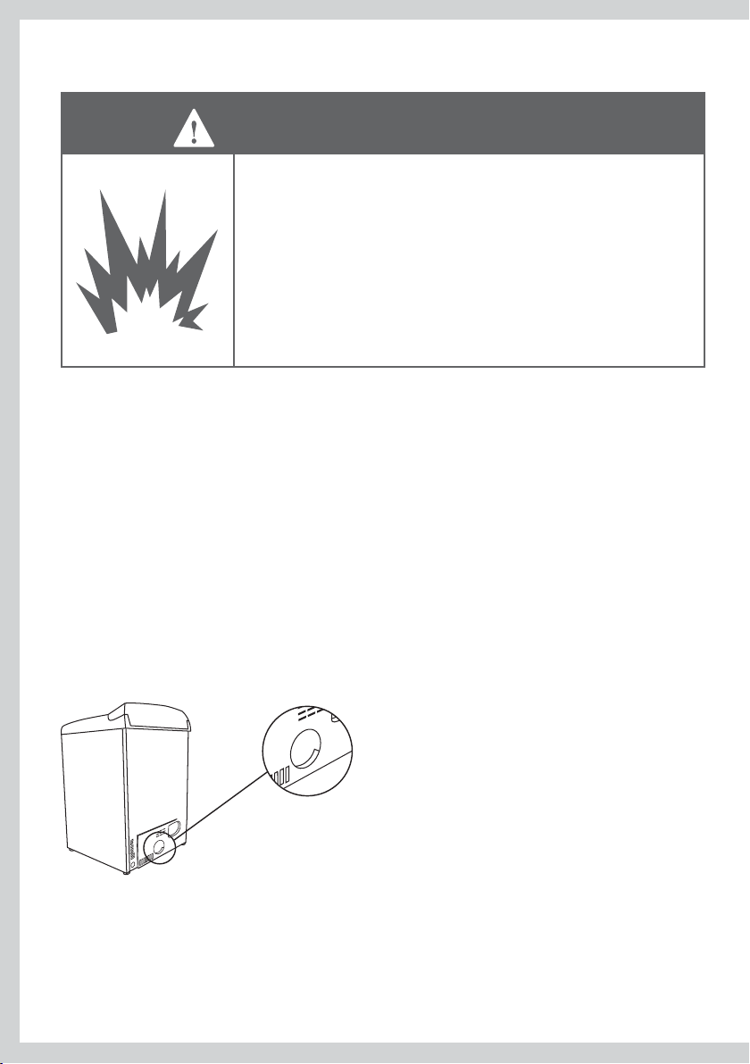
Requisitos de Colocación
ADVERTENCIA
Peligro de Explosión
La zona donde se ubica la secadora debe mantenerse vacía y libre
de materiales combustibles, gasolina y otros vapores y líquidos
inamables.
Coloque la secadora por lo menos 460mm (18 pulgadas) sobre el
piso si la instala en una cochera.
El no hacerlo puede causarle la muerte, provocar une explosión,
incendio o quemaduras.
La secadora deberá instalarse o colocarse en una zona que no esté expuesta al agua o al clima
exterior.
Es sumamente importante instalar la secadora en un lugar bien ventilado. Esta secadora debe
ventilar el aire hacia el exterior. No instale la secadora en ningún lugar o armario que no permita
la libre circulación de aire.
Asigne espacio suficiente detrás de la secadora para el escape. La toma de aire se encuentra en
la parte posterior de la se
secadora para la circulación de aire.
La zona donde se ubica la secadora debe mantenerse vacía y libre de materiales combustibles,
gasolina y otros vapores y líquidos inflamables. Una secadora produce pelusa combustible, por
lo cual hay que limpiar periódicamente la zona alrededor de la secadora para mantenerla libre de
pelusa.
cadora. Asegúrese de que exista suficiente espacio a cada lado de la
58

Requisitos de Colocación
Instalación en un armario o gabinete
Al instalar una secadora en un armario o gabinete debe
ADVERTENCIA
El área mínima total debe ser de 387cm
lavadora y secadora están en el mismo closet, las puertas deben tener un mínimo de 774cm
2
) de área abierta igualmente distribuida. Estas aberturas no deberán obstruirse jamás (una
(120 in
puerta de rejillas con flujo de aire mínimo es aceptable). Es necesario contar con separaciones de
instalación mínimas pero es recomendable incrementar el espacio de separación.
contar con un conducto de escape hacia el exterior.
No deberá instalar en el mismo armario o gabinete ningún
otro electrodoméstico que queme combustible.
2
(60 in2) de área abierta igualmente distribuida. Si la
espacio mínimo
requerido
1430mm (56 /”)
2
ES
25mm (1”)
25mm (1”) 25mm (1”)
Instalación en un baño o recámara
La secadora DEBE estar ventilada hacia el exterior. Consulte INFORMACIÓN DEL ESCAPE.
min 50mm (2”) min 76mm (3”)
área total de ventilación
774cm
2
(120 in)
59

Dimensiones
Ubicación del oricio de escape
Orificio de escape
114mm (4 /”)
298mm (11 /”)
Instalación en una Casa Móvil o Prefabricada
La instalación debe cumplir con la norma “CAN/CSA Z240 MH series Mobile Home Installation
Codes” o la “Manufactured Home Construction & Safety Standard, title 24, part 32-80” o cuando la
norma no es aplicable, con la norma “American National Standard for Mobile Home, AINSI/NFPA
NO. 501B”.
La secadora DEBE estar ventilada hacia el exterior con la terminación fijada firmemente a la
estructura de la casa móvil. (Consulte INFORMACIÓN DEL ESCAPE.)
El sistema de ventilación NO DEBE finalizar por debajo de la casa móvil o prefabricada.
El material del conducto de ventilación DEBE SER METAL.
El sistema de
No use pijas metálicas (tornillos) para lámina ni ningún otro dispositivo de fijación que se extienda
por el interior del sistema de ventilación del escape.
ventilación NO DEBE conectarse a ningún otro conducto, ventilación o chimenea.
Adicional a la anterior, para secadoras a gas:
DEBE usarse el JUEGO 14-D346-33 para fijar firmemente la secadora a la estructura.
Proporcione una abertura con una área libre de 161cm . (25 in) por lo menos para la introducción
de aire del exterior a la habitación de la secadora.
60

Escape
ADVERTENCIA
Peligro de Incendio
La secadora debe contar con escape hacia el exterior.
Utilice conductos de escape rígidos o metal exible de pared gruesa.
No utilice un conducto de escape de plástico.
No utilice un conducto de escape revestido de aluminio.
El no seguir estas indicaciones puede causar la muerte o provocar
un incendio.
La secadora debe contar con escape hacia el exterior. Esto evitará la acumulación de pelusa y
humedad dentro de la habitación en donde esté ubicada y reducirá el riesgo de incendio.
Este electrodoméstico deberá contar con escape al exterior.
Solo ducto metálico rigido o flexible debe ser usado para escape.
En Canada y Estados Unidos, para ductos flexible tipo laminado, debe ser identificado por el
fabricante para ser usado en la secadora y cumplir con las Norma de Duc
2158A) Secadoras de Ropa.
En Canada y Estados Unidos, el diametro del ducto de escape requerido debe ser de 102 mm (4”).
Los conductos de escape los puede adquirir en su tienda de electrodomésticos o en una
ferretería local.
Los conductos flexibles de plástico o revestidos de aluminio pueden plegarse, combarse,
perforarse, reducir la circulación de aire, alargar el tiempo de secado y por consiguiente, afectar la
operación de la secadora.
Deberá utilizarse un conducto de metal flexible o galvanizado rígido de un mínimo de 100mm
(4”) de diámetro. Utilizar conductos de más de 100mm (4”) de diámetro puede ocasionar una
mayor acumulación de pelusa.
Utilizar conductos de metal rígidos sin codos minimizará la acumulación de pelusa. Pueden
utilizarse conductos
pronunciadas que puedan doblar el conducto y ocasionar taponaduras. No utilice conductos de
plástico o metal flexible delgado.
Use cinta adhesiva industrial para unir las juntas. No use tornillos porque acumulan pelusa.
Mantenga los conductos lo más corto y derecho posible. No exceda las longitudes máximas de
los conductos de escape que se señalan más adelante en estas instrucciones de instalación.
No descargue la secadora dentro de una chimenea o respiradero de gas, una pared, el techo o
cualquier espacio oculto del batimento. No descargue la secadora debajo de la casa o casa móvil, un
porche, dentro de un quicio de ventana o en alguna otra área en donde pueda acumularse la pelusa.
El conducto de escape debe terminar en una campana de es
con un amortiguador de corriente invertida de aire hacia fuera para
evitar contracorrientes de aire y el ingreso de cualquier tipo de fauna
nociva. Nunca utilice campanas de escape con un amortiguador de
corriente magnético. La campana debe tener por lo menos 305mm
(12 pulgadas) de separación entre la parte inferior de la campana
y el piso o cualquier otra obstrucción. La apertura de la campana
debe apuntar hacia abajo. Nunca instale una pantalla por delante del
orificio de escape.
de metal flexible ancho pero hay que tener cuidado de evitar curvas
cape
tos de Transicion (Punto
305mm (12”)
ES
61
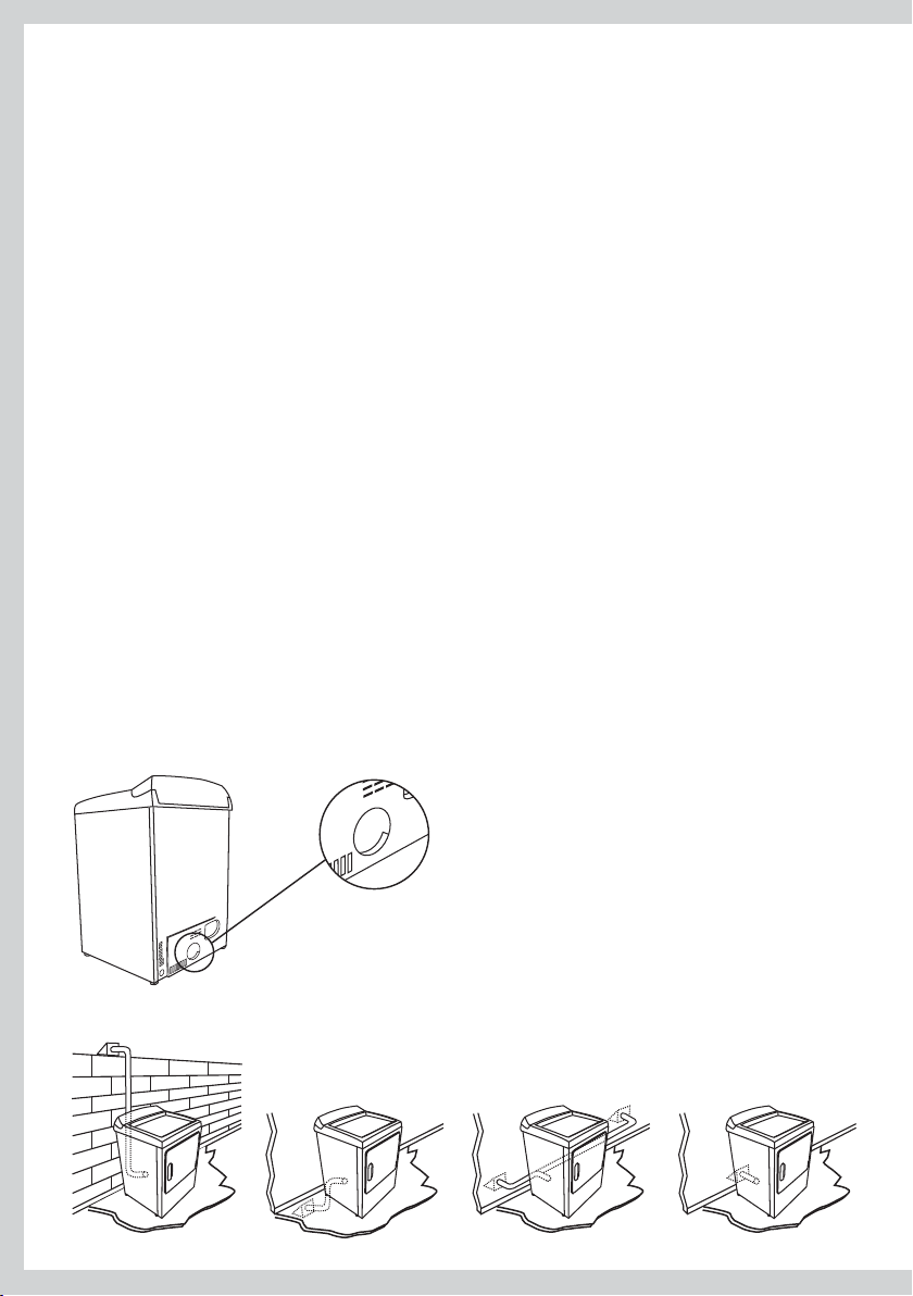
Escape
Para reducir la condensación, aísle todos los conductos que pasen por áreas que no emitan
calor. Coloque el conducto con una inclinación suave hacia la campana, para drenar la posible
condensación y reducir la acumulación de pelusa. Evite pandeos o bucles en el conducto, ya que
éstos pueden acumular o almacenar agua y pelusa.
Antes de poner en marcha un sistema de conductos de escape para secadoras, asegúrese de que:
No se haya utilizado ningún conducto de plástico u otro tipo de conducto potencialmente
combustible o conducto de revestimiento de aluminio flexible.
El conducto no esté perforado, retorcido o aplastado.
El conducto no exceda el largo máximo recomendado para la nueva secadora.
La persiana de la campana de escape se abre y c
La presión estática en el conducto de escape no exceda 250Pa (1 pulgadas), o sea menor a 0
pulgadas de columna de agua (es decir, presión negativa), al medirla con un manómetro en los
primeros 150mm (6”) del conducto, con la secadora operando en Fluff (sin calor).
El sistema de conductos de escape cumpla con todas las normas locales importantes, tanto
estatales como federales.
Los conductos deberán verificarse y limpiarse por lo menos una vez al año para extraer toda la
pelusa acumulada. Verifique frecuentemente que la persiana en la campana de escape se mueva
lo suficiente y se abra y cierre libremente.
Instalación en casa móvil o campers
Ponemos a su disposición un juego de instalación para casa móvil. (Véase Accesorios, página 56
así como las notas en la página 60).
ierra libremente y con suficiente movimiento.
Determine la longitud del conducto de escape
Más abajo encontrará distintos tipos de instalación para conductos de escape.
62

Escape
Elija una ruta que sea el camino más derecho y directo hacia el exterior. Planee la instalación de
manera que utilice la menor cantidad de codos y vueltas.
Al utilizar codos (conductos rígidos) o al realizar vueltas (conducto de metal flexible de pared
ancha), deje la mayor cantidad de espacio posible. Con conductos de metal flexible y pared
gruesa, pliegue el conducto gradualmente para obtener la curvas necesarias y así evitar
retorcimientos y vueltas de 90˚
recomendable
aceptable
Longitud Máxima del Conducto de Escape
La longitud máxima del sistema de conductos de escape depende de:
El tipo de conductos (rígidos o de metal flexible de pared gruesa).
La cantidad de codos y curvas utilizados.
Vea el gráfico de longitudes del con
para encontrar la longitud máxima del conducto a utilizar. No utilice tramos de conductos
mayores a aquellos especificados en los gráficos de longitudes de conductos de escape. (Véase
página siguiente).
Sistema de conductos de escape más largos de lo especificado:
Acumularán pelusa creando un potencial peligro de incendio.
Acortarán la vida de la secadora.
Reducirán el desempeño, dando por resultado tiempos de secado más largos y un incremento en
el consumo de energía.
ducto de escape que hace juego con su tipo de campana, 1
ES
Determine la cantidad de codos o curvas que necesitará. 2
En la tabla siguiente, encuentre la longitud máxima del conducto de metal rigido en la misma 3
línea que la cantidad de codos o curvas a utilizar. (Véase página siguiente)
La longitud total de tubo flexible metálico no debe exceder de 2.4m (8 ft).4
.
63
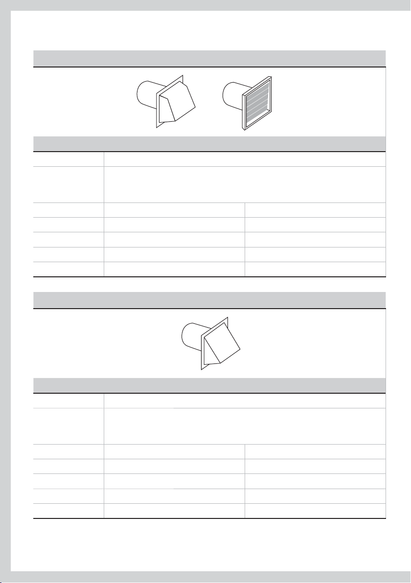
Longitud Máxima del Conducto de Escape
De preferencia utilice campanas de 4 pulgadas
Si utiliza una campana de 100mm (4”)
Longitud máxima del conducto de metal de 100mm (4”) de diámetro
Cantidad de
codos o curvas
de 90°
0 27.4m 90pies
1 18.3m 60pies
2 13.7m 45pies
3 10.7m 35pies
4 7.6m 25pies
Campana aceptable de 2 /” pulgadas
Rígidos
Si utiliza una campana de 60mm (2 /”)
Longitud máxima del conducto de metal de 100mm (4”) de diámetro
Cantidad de
codos o curvas
de 90°
0 18.3m 60pies
1 13.7m 45pies
2 10.7m 35pies
3 7.6m 25pies
4 4.6m 15pies
Para aquellos sistemas de escape que no se encuentren enlistados en los gráficos de longitud de
los conductos de escape (como par ejemplo, conexiones múltiples, tubos de aire y ventiladores
eléctricos), llame gratis a nuestro centro de atención a clientes: 1 888 9 FNP USA (1 888 9 367 872).
64
Rígidos

Opciones de Salidas de Escape
Esta secadora puede tener el escape en la parte trasera, derecha, izquierda y parte inferior del
gabinete y debe descargar al exterior.
Nota:
La secadora a gas no puede descargar por el lado derecho del gabinete.
Descarga hacia la derecha, izquierda o parte inferior de la secadora
Retire la placa desprendible inferior,
derecha o la del lado izquierdo, según
lo que convenga. Retire la pija que se
encuentra dentro del conducto de escape
de la secadora y guárdelo. Jale el conducto
fuera de la secadora. Proteja las orillas
filosas alrededor de la placa desprendible
y de la abertura de escape usando cinta
adhesiva.
Corte el conducto como se muestra y
guarde la sección “A”.
Retire la pija
y guárdela.
Retire la placa desprendible que
le convega (solamente una).
Agujero de fijación
B
A
9”
ES
Ubicación de la lengüeta
Localice la lengüeta a través de la abertura
trasera. La lengüeta se ubica en la parte
media de la base del aparato. Usando un
destornillador de punta plana, levante la
lengüeta hasta un ángulo aproximado de 45°.
Agregando conducto nuevo
Reconecte la porción cortada (A) del conducto
a la envolvente del soplador. Asegúrese de
que el agujero de fijación esté alineado con
la lengüeta en la base. Use la pija que guardó
previamente para asegurar el conducto en su
sitio a través de la lengüeta que se encuentra
en la base del aparato.
Doble 45° la
lengüeta
Agujero
fijación
Porción “A”
Escape lado
izquierdo
65

Opciones de Salidas de Escape
Agregando un codo y conducto para que el escape sea por el lado del gabinete.
Pre-ensamble un codo de 100mm (4”)
de 100mm (4”). Envuelva cinta para conducto
alrededor de la junta.
Introduzca el conjunto del conducto, con el codo
primero a través de la abertura lateral y conecte el
conducto interno de la secadora.
conducto
Escape puede
ser añadido al
lado derecho
o izquierdo
PRECAUCIÓN!
Asegúrese de no jalar ni dañar los cables eléctricos
dentro de la secadora al introducir el conducto.
Aplique cinta para conducto como se muestra, en
la junta entre el conducto interno de la secadora y
el codo.
PRECAUCIÓN!
Las juntas de conducto interno deben asegurarse
usando cinta, de lo contrario podrían separarse
generando un riesgo de seguridad.
Agregando un codo para escape a través de la parte inferior del gabinete
Inserte el codo a través de la abertura trasera y conéctelo al
conducto interior de la secadora.
Aplique cinta para conducto en la junta entre el conducto
interior de la secadora y el codo, como se muestra en la
página 61.
Cinta para
conducto
Cinta para
conducto
PRECAUCIÓN!
Las juntas de conducto interior deben asegurarse con cinta,
de lo contrario pueden separarse generando un riesgo de
seguridad.
Instalando la placa de cubierta a la parte trasera del gabinete (Escape lateral e inferior)
Conecte codos y conducto estándar metálico para
completar el sistema de escape. Cubra la abertura de
la parte trasera con una placa (Juego No. WE1M454)
disponible en su Centro de Servicio local. Coloque la
secadora en su ubicación final.
66
Placa (juego WE1M454)

Conducto de Escape
ADVERTENCIA
Peligro de Incendio
Utilice conductos de escape de metal pesado.
No utilice conductos de escape de plástico.
No utilice conductos de escape revestidos de aluminio.
El no seguir al pie de la letra este instructivo puede causar muerte
o incendio.
Lea la sección acerca de escape (páginas 61 – 66) antes de instalar el sistema de escape, para 1
determinar la longitud máxima permitida del conducto de escape.
No utilice tornillos de chapa de metal al ensamblar los conductos. Utilice siempre cinta adhesiva
industrial adecuada. Nunca utilice material de escape flexible de plástico o de metal delgado.
El orificio de escape se encuentra ubicado cerca del centro de la parte trasera de la secadora. 2
Asegúrese de conectar el conducto de escape a la secadora solamente con cinta adhesiva
industrial. Esto evitará que la pelusa y el polv
298mm (11 /”)
o escapen de la secadora y del sistema de escape.
Orificio de escape
114mm (4 /”)
ES
La ruta del respiradero de escape puede ir desde la parte posterior de la secadora hacia arriba, 3
hacia abajo, izquierda, derecha o directamente hacia el exterior. Remítase al diagrama.
67

Instalación
Encontrará las piezas y el material de lectura empacados dentro del tambor de la secadora.
ADVERTENCIA
Peligro por Exceso de Peso
Se necesitan dos o más personas para mover e instalar la
secadora.
El no hacerlo así puede ocasionarle daños en la espalda o de
otro tipo.
Quite el embalaje de la máquina exclusivamente enfrente del cliente.
Lo anterior garantizará que el electrodoméstico llegue en condiciones óptimas y originales de
fábrica y reducirá el riesgo de daños al transportarlo a su destino final.
Desempacar
Asegúrese de que la secadora se encuentre en un lugar adecuado para su instalación.
Si la instala junto a otro electrodoméstico, considere instalar, por ejemplo, la secadora antes de la
lavadora, ya que le permitirá un mejor acceso a las conexiones eléctricas y al escape.
Retirar los cojines de las patas de la secadora
Ladee la secadora hacia los lados y retire los cojines de embarque de anime jalando por los lados
y separándolos de las patas de la secadora. Asegúrese de remover todas las piezas de anime
alrededor de las patas.
68

Instrucciones de Conexión a Tierra para
Secadoras a Gas y Eléctricas
ADVERTENCIA
Peligro de Electrocutamiento
Asegúrese de que este electrodoméstico esté conectado a un
tomacorrientes aterrizado a tierra.
No utilice un adaptador.
No utilice una extensión.
Si no sigue al pie de la letra estas instrucciones puede provocar la
muerte, incendio, o electrocutamiento.
ADVERTENCIA
Peligro de Electrocutamiento
Verique con un electricista calicado o con el servicio
técnico si tiene dudas al respecto o para cerciorarse que el
electrodoméstico esté bien aterrizado a tierra.
No modique el enchufe si no encaja en el tomacorrientes.
Pida que le instalen el tomacorrientes adecuado y que lo haga un
electricista calicado.
Si no sigue al pie de la letra estas instrucciones puede provocar la
muerte, incendio, o electrocutamiento.
ES
Conexión a Tierra para un Electrodoméstico conectado vía un Cordón
Este electrodoméstico debe estar conectado a tierra. En el caso de mal funcionamiento o
avería, la conexión a tierra reducirá el riesgo de electrocutamiento al ofrecer una vía de menos
resistencia para la corriente eléctrica. Cuando este electrodoméstico se encuentre equ
con un cordón que cuente con conductor de toma a tierra del equipo y un enchufe de toma
a tierra, el enchufe deberá conectarse a un tomacorrientes apropiado que haya sido instalado
y conectado a tierra correctamente, de acuerdo con todas las normas y reglamentos locales
vigentes, o en su defecto, con el “National Electrical Code ANSI/NFPA 70”, o el “Canadian Electrical
Code CSA C22.1”.
La conexión incorrecta del conductor de toma a tierra del
ADVERTENCIA
Remítase a las páginas 70 a 82 para mayor información acerca del cableado de secadoras eléctricas,
incluyendo los requisitos de conexión a tierra para un electrodoméstico de cableado directo.
Verique con un electricista calicado o con el servicio
técnico si tiene dudas al respecto o para cerciorarse que el
electrodoméstico esté bien aterrizado a tierra.
ipado
.otneimatucortcele ed ogseir odatluser rop rad edeup opiuqe
69

Especificaciones Eléctricas, para Modelos
Eléctricos Únicamente
ADVERTENCIA
Peligro de Electrocutamiento
Utilice un cable eléctrico nuevo aprobado UL/CSA de 30 amperes
o un cable directo.
Utilice un protector UL aprobado.
Desconecte la electricidad antes de realizar las conexiones eléctricas.
Conecte el cable neutro (blanco o cable central) a la terminal central.
En todas las instalaciones de cuatro alambres, quite la conexión a tierra
y conecte el alambre a tierra al tornillo verde de conexión a tierra.
Conecte los 2 cables de suministro restantes a los 2 terminales
restantes.
Ajuste con rmeza todas las conexiones eléctricas.
El no seguir estas indicaciones puede causarle la muerte,
provocar un incendio o electrocutamiento.
Nota:
El diagrama eléctrico esta dentro del copete.
La secadora debe conectarse a un
circuito de ramal individual, no utilice una
extensión.
Antes del uso asegúrese de que exista una
tierra apropiada.
El suministro del circuito derivado
deberá ser de 60 Hz de 220/240V o 208V.
Las especificaciones eléctricas puede
encontrarlas en la etiqueta de información
localizada en el frente del aparato al abrir
la puerta. Se necesita de un fusible de 30
amperes o un cortacorrientes en cada una
de las líneas.
Si utiliza un cable de alimentación, el cable debe conectarse a
El cable de alimentación NO se suministra con los modelos eléctricos de secadoras para los
Estados Unidos.
Esta secadora se suministra con el gabinete conectado a tierra a través del neutro en el bloque de
conexión. Si la secadora se instala (1) en una instalación nueva de circuito ramal, (2) en un casa
móvil o camper, (3) en un vehículo de uso recreativo, (4) en una zona donde las normas locales
no permitan la conexión a tierra a través del neutro, el enlace a tierra del electrodoméstico debe
quitarse y reemplazarse por un cable o cordón de alimentación de 4 alambres, o un cable de
conexión a tierra separado.
No vuelva a utilizar un cable o cordón de alimentación de una secadora vieja. El cableado de
al
imentación eléctrica deberá mantenerse en el gabinete de la secadora con un protector UL adecuado.
70
Si los códigos locales lo permiten,
puede agregarse un cable externo
de conexión a tierra (no incluido),
el cual cumpla con los códigos
locales conectándolo al tornillo
color verde de tierra en la parte
trasera de la secadora, y a una
tubería de agua fría aterrizada y
metálico o a otra tierra establecida.
un tomacorrientes de 30 amperes.

Instrucciones de Conexión a Tierra para Secadoras
a Gas y Eléctricas
Suministro Eléctrico para Secadoras Eléctricas: (Solo para Canada)
120 / 240 V o 120 / 208 V de 60 Hz sinusoidal suministrado por
un circuito individual con un fusible o disyuntor de 30 amperes
en cada una de las líneas.
Conectar a un receptáculo de pared de 30 amperes como
muestra la figura
La instalación debe cumplir con las normas locales. No
modifique el conector para ajustarse a otro receptáculo.
Suministro Eléctrico para Secadoras a Gas:
120 V 60 Hz sinusoidal suministrado por un circuito protegido
con un fusible o disyuntor de 15 o 20 amperes.
Conectar a un receptáculo de pared como muestra la figura
La instalación debe cumplir con las normas locales o la no
“CSA C22.1 Canadian Electrical Code part 1”.
Y
rma
G
X
W
Especificaciones del Cable de Alimentación en
los Estados Unidos
ES
ADVERTENCIA
Peligro de Electrocutamiento
Nunca deje de colocar la cubierta del bloque de conexiones.
El no seguir estas indicaciones puede causarle la muerte,
provocar un incendio o electrocutamiento.
Conexiones de 4 alambres (debe ser utilizado para instalación en casa móvil)
Nota:
Desde el 1 enero 1996, el Código National Eléctrico requiere que las construcciones nuevas
utilicen una conexione a 4 cables para la secadora eléctrica.
Desconecte el disyuntor (30 amp) o remueva el fusible del circuito.1
Asegurase que el cordón de alimentación este desconectado del receptáculo.2
Retire la cubierta del cordón de alimentación de la parte trasera inferior.3
Desconecte y descarte la cinta de conexión a tierra. Guarde el tornillo verde de tierra para el paso 7.4
Instale la abrazadera sujetadora de cables de 5 /” UL reconocida en el orificio de entrada del suministro
de energía. Inserte el cable de alimentación a través de la abrazadera sujetadora de cables.
Conecte el cable de alimentación como se indica a continuación: 6
A. Dos alambres vivos al tornillo exterior del bloque de terminales (marcado L1 y L2).
B. El alambre neutro (azul) al tornillo central del bloque de terminales (marcado N).
71

Especificaciones del Cable de Alimentación en
los Estados Unidos
Afiance el alambre de masa (tierra) (verde, verde y amarillo o sin forro) al tornillo verde de tierra 7
(orificio encima de la ménsula de la abrazadera sujetadora de cables). Apriete todos los tornillos
del bloque de terminales firmemente.
Asegure el cable de alimentación firmemente a la abrazadera sujetadora cable.8
Instale nuevamente la cubierta. 9
Retire la lámina de conexión y
descártela, guarde el tornillo de
tierra verde
Tornillo
(3)
Cubierta
Instalación de un cordón eléctrico de 3 alambres
Si la norma local lo requiere, instale la tierra externa (no se proporciona) a la tubería metálica de
agua fría o a cualquier otro elemento conectado a tierra de acuerdo con las especificaciones de
un electricista calificado.
D
esconecte el disyuntor de circuito (30 amp) o retire el fusible del circuito de la secadora.1
Asegurase que el cordón de alimentación esta desconectado.2
Retire la cubierta del cordón de alimentación en la parte trasera inferior.3
Instale la abrazadera sujetadora de cables de 4 /” UL reconocida en el orificio de entrada del suministro
de energía. Inserte el cable de alimentación a través de la abrazadera sujetadora de cables.
Conecte el cable de alimentación como se indica a continuación: 5
A. Dos alambres vivos al tornillo exterior del bloque de terminales (marcado L1 y L2).
B. El alambre neutro (azul) al tornillo central del bloque de terminales (marcado N).
Cerciórese de asegurar la cinta de conexión a tierra con el terminal
al tornillo verde de tierra en la parte posterior del gabinete. Apriete todos los tornillos del bloque
de terminales firmemente.
Asegure el cable de alimentación firmemente a la abrazadera sujetadora de cables.7
Instale nuevamente la cubierta.8
Tornillo de
tierra verde
Cubierta
72
Tornillo
(3)
Neutro
(blanco)
Vivo
Relocalice el tornillo
de tierra verde aquí
1L
N
2L
Vivo
Neutro
(blanco)
Lamina de conexión
L1
L2
Retenedor de cable
/” reconocido UL
Vivo
Soporte de retenedor de cable
Retenedor de cable
/” reconocido UL
Vivo
Cable verde o amarillo
Soporte de retenedor de cable
4 conductores de cobre #10 AWG
mínimo o cordón de alimentación
120/240V 30A usado para
secadoras y provisto de terminales
que aseguran su retención.
neutro del bloque (centro) y 6
3 conductores de cobre #10 AWG
mínimo o cordón de alimentación
120/240V 30A usado para
secadoras y provisto de terminales
que aseguran su retención.

Especificaciones para Gas (Modelos a Gas Únicamente)
La instalación debe cumplir con las normas locales, o en su defecto, con el “National Fuel Gas
Code ANSI Z223.1/NFPA 54” o el “Canadian Natural Gas and Propane Installation Code, CSA B149.1.”
ADVERTENCIA
Peligro de Explosión
La instalación y el servicio los deberá llevar a cabo un contratista,
plomero o técnico de gas calicado, autorizado por el Estado,
Provincia o Región en donde vaya a instalarse el electrodoméstico.
Utilice una línea de suministro de gas nueva aprobada por AGA o
CSA.
Instale una válvula de paso en un lugar de fácil acceso.
Utilice solamente una válvula de paso de gas aprobada para usarse
dentro del Estado, Provincia o Región en donde vaya a instalarse
este electrodoméstico.
Ajuste con rmeza todas las conexiones a gas.
El no seguir al pie de la letra este instructivo puede causar muerte,
explosión o incendio.
Tipo de gas
Su secadora debe contar con el quemador correcto para el tipo de gas que utilice en su hogar.
La información sobre quemadores se encuentra en la placa de identificación, ubicada en la parte
delantera al abrir la puerta. Si esta información
hogar, póngase en contacto con su proveedor o centro de servicio técnico Fisher & Paykel local.
Gas natural
Esta secadora está lista para utilizarse con Gas Natural.
Su diseño fue certificado por CSA International para gases LP (propano o butano), con la
conversión apropiada.
Conversión a gas LP
Si la secadora va a funcionar con gas LP (propano líquido o butano), ésta deberá contar con un
proceso de conversión. Para lo anterior, utilice solamente el juego de conversión aprobado por
Fisher & Paykel que se encuentra enlistado en los Accesorios del a página 56. No la utilice con un
gas diferente sin consultar al proveedor de gas p
Para lograr un desempeño seguro y correcto, el proceso de conversión de la secadora deberá
realizarlo personal calificado de servicio técnico o instalación.
Su proveedor local de Fisher & Paykel cuenta con juegos de conversión para gas natural y LP (véase
Accesorios, página 56). Si hubiera que hacer otro tipo de conversiones, verifique con su servicio
público local de gas para obtener información específica en cuanto a los requisitos de conversión.
no coincide con el tipo de gas disponible en su
rimero.
ES
73

Conexión de Gas para Su Secadora (Modelos a
Gas Únicamente)
En las roscas macho de todas las conexiones no acampanada use compuesto o cinta para rosca
apropiada para el tipo de gas que se utilice (gas natural o LP).
Nunca utilice una llama para verificar la existencia de fugas de gas.
Esta secadora operará satisfactoriamente hasta altitudes de 2000m (6500pies) por encima del
nivel del mar, a la clasificación BTU indicada en la placa de modelo/serie. Se necesitará hacer
ajustes del fluido al quemador si se opera por encima de esta altura.
Durante cualquier prueba de presión del sistema de tuberías de suministro de gas, la secadora
deberá aislarse del sistema de tuberías de suministro de gas cerrando la válvula de paso.
Encendido del gas
Esta secadora cuenta con un sistema de encendido automático para encender el quemador. No
existe una llama piloto ardiendo dentro de la secadora.
Cómo conectarla al suministro de gas
La línea de suministro de gas debe ser de 12.7mm (1 /“).
Hay que instalar una válvula individual manual de paso en la línea de suministro de gas a no más 2
de 1.8m (6pies) de la secadora, de acuerdo con el “National Fuel Gas Code ANSI Z223.1/NFPA 54”
para los Estados Unidos, o de acuerdo con el ”B149.1 Natural Gas and Propane Installation Code”
para Canadá.
Hay que instalar una toma obturada de 3 / de pulgada NPT para permitir que se pueda verificar
la presión del fluido de gas. Debe ser accesible para la conexión de calibre de prueba e
inmediatamente hacia arriba, de la conexión de gas a la secado
ra.
74
Toma obturada de /”
Válvula de paso de gas
Línea de suministro
de gas de /” NPT

Conexión de Gas para Su Secadora (Modelos a
Gas Únicamente)
Deberá utilizarse un conector que cumpla con las especificaciones ANSI Z21.24/CSA6.10 para 4
conectar a la secadora con el suministro de gas.
Si se utiliza una tubería flexible, se debe instalar un codo en la tubería en la parte trasera de la 5
secadora al cual deberá conectarse la tubería flexible. Esto minimizará el daño al tubo al mover
hacia atrás la secadora. Utilice un juego de conexión de tubería flexible que haya sido diseñado
para ser utilizado en una secadora de ropa. Este juego debe contar con las uniones necesarias
para conectar a los extremos de la tubería. Asegúrese de seguir todas las instrucciones proveídas
con el juego.
Para gas
compatible con gas LP.
Desconecte y deseche la tubería flexible vieja.7
El tubo de gas que sale en la parte trasera de su secadora tiene una rosca de 8 /” NPT. Retire la
tapa protectora y aplique el sellador o cinta a la rosca. El sellador de rosca debe ser apropiado
para el tipo de gas que vaya a utilizar.
natural no se debe utilizar una tubería de cobre, y si se la usa para gas LP, deberá ser 6
Aplique sellador
de rosca
ES
Retire la tapa
Rosca de cañería
de /” NPT
Codos requerido para
tubería flexible
Cómo completar la conexión
Utilice llaves inglesas para ajustar todas las juntas, pero no las ajuste demasiado.1
Abra la válvula de suministro de gas y verifique todas las juntas cepillándolas con una solución no 2
corrosiva para detectar fugas. La aparición de burbujas indicará fugas. Si existiera alguna fuga,
cierre inmediatamente la válvula y corrija las fugas.
existan más fugas.
Vuelva a comprobar y repita hasta que no
75

Nivelación de la Máquina
Verifique que la secadora se encuentre nivelada, y realice los ajustes necesarios.
Ajuste las 4 patas de nivelación para ajustar con la altura de la lavadora. La secadora DEBE ESTAR
NIVELADA y permanecer firme sobre sus 4 patas niveladoras.
Nivele del frente hacia
la parte trasera
4 patas niveladoras
Nivele lado a lado
Lista Final de Comprobación de la Instalación
Verifique que:
No se utilice plástico o metal flexible delgado en los conductos de escape.
El escape se realice por medio de conductos rígidos o conductos de metal flexible de pared gruesa.
Todas las juntas de los conductos tengan cinta adhesiva industrial. No estén conectados o unidos
con tornillos ni con otros dispositivos de ajuste que se extiendan hacia el interior del conducto.
Los conductos estén limpios y conectados a la secadora.
La secadora está nivelada.
Además, para modelos de secadora eléctricos únicamente, verique que:
La secadora esté enchufada directamente a un tomacorrientes aprobado y que se encuentre
conectada a tierra correctamente.
La secadora arranque, se caliente, se enfríe y se apague.
Además, para modelos de secadora a gas únicamente, verique que:
La secadora esté enchufada directamente a un tomacorrientes aprobado y que se encuentre
conectada a tierra correctamente.
Todos los tubos de unión en la línea de gas se hayan verificado para evitar fugas de gas.
La temperatura de escape se incremente, confirmando así que está encendida.
– Si no se enciende al inicio, se deberá a la presencia de aire en la línea de gas o al bajo volt
del suministro eléctrico.
– La válvula reguladora de gas pudiera no abrir si la corriente eléctrica cae por debajo de los
105 voltios.
76
aje

Características
Extra Care
Use esta opción para reducir las arrugas en la ropa. Esta opción provee
aproximadamente 15 minutos de rotación sin calor después que la ropa esta seca.
Esta opción solo puede ser utilizada con Ciclos Automáticos.
Nota:
Si la opción de Signal es seleccionada, la señal sonará al final del tiempo de
secado y sonará varias veces durante el ciclo de Extra Care. Le recordará que el
ciclo ha sido completado.
Signal
Esta alarma sonará justo antes del final del ciclo para recordarle de sacar su ropa.
Si usted selecciona la opción Extra Care la alarma sonará al final del tiempo de
secado y sonará varias veces durante el ciclo de Extra Care.
Esto le recordará que el ciclo de secado ha sido completad
su ropa.
Nota:
Saque pronto las prendas al oír la señal. Coloque la ropa en ganchos para evitar
las arrugas.
Use especialmente la señal para tejidos como poliéster y planchado permanente.
Estos tejidos deben ser sacados rápidamente para evitar las arrugas.
o y usted puede sacar
ES
Reset Options
Su selección cancela todas las opciones que habían sido seleccionadas.
Luz del Tambor
Una luz en el interior de la secadora ayuda a facilitar la descarga.
Rejilla de Secado (Opcional en algunos modelos)
Una rejilla de secado puede ser usada para secar artículos como
peluches, almohadas o suéteres lavables.
Enganche la rejilla sobre el filtro de pelusa de manera que la rejilla
quede adentro del tambor de la secadora.
Nota:
La rejilla de secado debe ser usada en el ciclo “Timed”. No use la
rejilla de secado con otra ropa dentro de la secadora.
77

Instrucciones de Operación del Panel de Control
Ciclos de Secado Automáticos
(El ciclo detecta el secado automáticamente)
Hay dos niveles de secado automático:
Estas dos selecciones secan su ropa a diferentes grados dependiendo del nivel de secado que
usted desee.
More Dry (+) y Less Dry (–).
Automatic Permanent Press – Para telas sintéticas. Seleccione More Dry (+) para telas pesadas
Less Dry (–) para telas livianas.
y,
Automatic Permanent Press – Para ropa delicada y de cuidado especial. Seleccione More Dry
(+) para las tela más grandes y, Less Dry (–) para telas más pequeñas.
Automatic Cottons – Para algodones y la mayoría de linos. Para la mayoría de cargas seleccione
la ubicación marcada con un asterisco *. Seleccione
More Dry (+) para telas pesadas y, Less Dry
(–) para telas ligeras.
Fabric Care Settings
FLUFF – para los artículos que requieran de un secado sin calor. Ideal para airear la ropa o para
refrescar prendas que hayan estado guardadas en una maleta o dentro de un cajón.
COTTON REGULAR – para secar algodones en general como sábanas, sudaderas y ropas tejida.
Este ciclo utiliza calor alto para secar la ropa rápidamente. Recomendable para las prendas con la
etiqueta que indica “meter a la secadora”
PERMANENT PRESS – para secar telas ligeras. Se utiliza un calor medio para reducir el efecto
de arrugado. Ideal para algodones lige
etiqueta “meter a la secadora con calor medio”. Este ciclo selecciona automáticamente la opción
DEWRINKLE para reducir el efecto de arrugado de la ropa.
KNITS DELICATES – para calentar artículos sensibles. Este ciclo utiliza calor bajo. Utilice esta
configuración cuando las etiquetas de cuidado de la ropa recomienden configuraciones de calor
bajo, o para prendas que contengan fibras sintéticas, en donde el sobrecalentamiento puede
ocasionar daños a la fibras.
78
ros, ropa casual y artículos con la indicación en la

Instrucciones de Operación del Panel de Control
Ciclos de Tiempo de Secado
(Ciclos funcionan por un tiempo seleccionado)
La secadora tiene tres ciclos de tiempo, estos ciclos pueden ser tiempos de secado de 40, 60 o 80
minutos e incluyen funciones de
secará por un periodo de tiempo determinado.
Timed Dry – Coloque el Selector de Ciclo en el tiempo de secado deseado.
Damp Dry –
Dewrinkle – Para retirar arrugas de la ropa que esta limpia y seca o que esta ligeramente
húmeda, coloque el Selector de Ciclo en la ubicación de Dewrinkle.
Nota:
Los tiempos de secados pueden variar de acuerdo al tipo de calor utilizado (eléctrico o gas
natural)
escape.
Para ropa parcialmente seca, coloque el Selector de Ciclo en la ubicación de Damp Dry.
, tamaño de la carga, tipo de tela, humedad de la ropa y condiciones de los conductos de
DAMP DRY y DEWRINKLE. Si son seleccionadas, su secadora
ES
79

Invirtiendo la Puerta
Herramientas necesarias:
Un desarmador Phillips estándar del #2 (De Cruz)
Una Espátula de Modelado con cinta adhesiva en la punta
Pinzas de punta fina
Abra la puerta y retire los tapones que se encuentran frente a 1
las bisagras.
Con la puerta completamente abierta, retire los tornillos del 2
fondo de cada bisagra, en el frente de la secadora.
Introduzca estos tornillos hasta la mitad de la cuerda dentro de 3
los orificios superiores, para cada bisagra, en el lado opuesto
a donde usted retiró los tapones. Aplique presión firme para
insertar los tornillos autorroscantes en perforaciones sin cuerda.
Afloje hasta la mitad el tornillo superior de cada bisagra sobre 4
el frente de la secadora.
Con una mano sosteniendo la parte superior de la puerta y la 5
otra deteniendo la parte inferior, retire la puerta de la secadora
levantándola hacia arr
Gire la puerta 180 grados. Insértela en el lado opuesto a la 6
abertura, moviendo la puerta hacia adentro y hacia abajo, hasta
que las bisagras superior e inferior descansen en los tornillos
superiores insertados en el paso 3.
Retire los tornillos restantes del lado de la apertura donde la 7
puerta fue retirada. Con estos tornillos asegure cada bisagra en
el fondo.
Apriete los dos tornillos superiores de cada bisagra. Reinserte 8
los tapones plásticos en las perforaciones del lado donde retiró
la puerta.
80
iba y hacia afuera.

Inicio Rápido
ADVERTENCIA
ADVERTENCIA
Para reducir el riesgo de incendio, electrocutamiento o
daños personales, lea las INTRUCCIONES DE SEGURIDAD
IMPORTANTES, antes de operar este electrodoméstico.
Peligro de Incendio
Seque sólo telas que hayan sido lavadas con agua.
No utilice calor para secar artículos que contengan espuma
de caucho o algún material de textura de hule similar. Seque
únicamente en el ciclo de FLUFF.
Cualquier secadora de ropa produce pelusa combustible y deberá
evacuarse hacia el exterior. Tenga cuidado de que la pelusa no
se acumule en torno a la abertura de escape, así como en el área
circundante.
El no seguir estas indicaciones puede causarle la muerte o daños
personales.
ES
ADVERTENCIA
Peligro de Explosión
La zona donde se ubica la secadora debe mantenerse vacía y libre
de materiales combustibles, gasolina y otros vapores inamables.
Ninguna lavadora quita completamente los rastros de aceite.
No intente secar nada que haya entrado en contacto con
gasolina, aceite u otro material inamable (incluyendo aceites de
cocina).
El no seguir estas indicaciones puede causarle la muerte o daños
personales.
81

Cómo Utilizar Su Secadora
Verifique las etiquetas de cuidado de telas dentro de las prendas para determinar si el fabricante
recomienda el secado de éstas en una secadora de tambor. (Véase la sección de etiquetas de
cuidado de telas).
1. Clasicar
Es mejor si clasifica sus prendas antes de meterlas a la secadora. Separe la ropa en tipos de
prendas similares y cargas que tengan tiempos de secado similares.
Los artículos más pesados (ej. toallas, playeras y sábanas de franela) se secan mejor en forma
separada de los artículos ligeros (ej. sintéticos, sábanas de varios tipos de algodón y camisas).
Esto evitará la posibilidad de que algunos artículos queden demasiado secos mientras otros aún
estén húmedos. Ayudará también a extender la vida de sus p
Secar la ropa tan pronto como la lavadora haya terminado reducirá la posibilidad de que salga
arrugada, así como la posibilidad de que las prendas blancas se tiñan con las prendas de color.
Recomendamos que las prendas estampadas se pongan por el revés para garantizar que el
estampado no se pegue al tambor. Las prendas que con ganchos o cremalleras deberán sujetarse
y en la medida posible, ponerlas en la secadora por el revés. Coloque la ropa interior en una red
para protegerla de otras prendas dentro de la carga.
Use la rejilla de secado para prendas de lana (disponible como accesorio opcional).
rendas y ropas de cama.
2. Cargar
Las prendas deberán cargarse adecuadamente para minimizar la posibilidad de que se arruguen
y garantizar que la carga se seque de manera uniforme. Asegúrese que haya el suficiente espacio
para que las prendas giren libremente durante el proceso de secado. Cargue de acuerdo con el
espacio que necesitan las prendas al estar secas, en vez de considerar cuando estén húmedas.
La regla general es: una carga de lavado = una carga de secadora.
Es ideal secar las prendas de “planchado permanente” juntas en un ciclo separado con la opción
EXTRA CARE activada. Esto ayudará a reducir las arrugas en la ropa y la necesidad de plancharla.
3. Filtro para Pelusa
Limpie el filtro atrapa pelusa cada vez que use la secadora, antes o después de cada carga.
Es importante que opere su secadora con el ltro atrapa pelusa puesto en su sitio en todo
momento.
82

Cómo Utilizar Su Secadora
4. Seleccionar un Ciclo
Su secadora cuenta con un número de ciclos FABRIC CARE CYCLES que pueden utilizarse para
secar diversos tipos de prendas:
Seleccione un ciclo automático o de tiempo. Vea abajo las Descripciones de los Ciclos.
Seleccione un ciclo de secado de acuerdo con el tipo de carga que vaya a secar. Todas la telas
requieren de diversos tipo de secado, de manera que es importante elegir el ciclo que mejor se
adapte a la carga de ropa. Si su carga contiene principalmente artículos delicados, en mejor que
selecciones el ciclo
Siga siempre las instrucciones de las etiquetas de cuidado de telas por parte del fabricante
cuando vaya a secar la ropa.
Si no está seguro de qué temperatura seleccionar para la carga, lo mejor será seleccionar un calor
más bajo que uno alto,
COTTON REGULAR.
FLUFF – para los artículos que requieran de un secado sin calor. Ideal para airear la ropa o para
refrescar prendas que hayan estado guardadas en una maleta o dentro de un cajón.
COTTON REGULAR – para secar algodones en general como sábanas, sudaderas y ropas tejida.
Este ciclo utiliza calor alto para secar la ropa rápidamente. Recomendable para las prendas con la
etiqueta que indica “meter a la secadora”
PERMANENT PRESS – para secar telas ligeras. Se utiliza un calor medio para reducir el efecto
de arrugado. Ideal para algodones ligeros, ropa casual y artículos con la indicación en la
etiqueta “meter a la secadora con calor medio”. Este cicl
DEWRINKLE para reducir el efecto de arrugado de la ropa.
KNITS DELICATES – para calentar artículos sensibles. Este ciclo utiliza calor bajo. Utilice esta
configuración cuando las etiquetas de cuidado de la ropa recomienden configuraciones de calor
bajo, o para prendas que contengan fibras sintéticas, en donde el sobrecalentamiento puede
ocasionar daños a la fibras.
KNITS DELICATES.
ej. los ciclos
KNITS DELICATES o PERMANENT PRESS en vez del ciclo
o selecciona automáticamente la opción
ES
Extra Care
Minimiza la posibilidad de que se formen arrugas en la ropa si no fuera capaz
de sacar la ropa de la secadora de inmediato.
83

Cómo Utilizar Su Secadora
5. Seleccionar el Nivel de Secado
Se puede modificar el nivel de secado deseado. Existen dos niveles de secado para elegir:
MORE DRY (+)
LESS DRY (–)
Remítase a la página 78 para ver las descripciones de los Niveles de Secado.
Al final del ciclo, si la ropa se encuentra todavía húmeda o está demasiado seca, la próxima vez
ajuste el nivel de secado en el Selector de Ciclo para que satisfaga sus preferencias personales.
6. Seleccionar el Proceso de Secado
Existen dos formas en las cuales su secadora es capaz de secar la ropa: utilizando la opción
AUTOMATIC DRYING CYCLES o la opción TIMED DRY.
AUTOMATIC DRYING
En AUTOMATIC DRYING, su secadora reconoce automáticamente el nivel de secado de la carga
y se apaga cuando la ropa esté seca. La computadora interna de la secadora mide el contenido
de humedad de la carga utilizando barras sensoras de metal y junto a un sensor de temperatura,
determina el momento en que la ropa ha alcanzado el nivel de secado seleccionado (Vea arriba
– Seleccionar el Nivel de Secado).
Para un cuidado óptimo de la ropa, haga que el ciclo concuerde con la carga.
DRYING proporciona a menudo los mejores resultados y por ende minimiza los costos de
energía que
Un ciclo automático basado en el sensor de humedad, no funcionará cuando se utiliza la rejilla de
secado.
TIMED DRY.
AUTOMATIC
TIMED DRY
Existen tres ciclos de secado con tiempo medido. Podrá escoger entre 40, 60 y 80 minutos. Se
incluye un periodo de
Para seleccionar un ciclo de tiempo medido, coloque el Selector de Ciclo en el tiempo deseado
para el funcionamiento de la secadora. Durante el ciclo, el Selector de Ciclo rotará hacia el final
del ciclo.
COOL DOWN en los tres ciclos.
Durante TIMED DRY, la secadora no determinará automáticamente cuando la ropa esté
lista y seca. Esto puede provocar un exceso de secado. Le recomendamos que seque su
ropa durante un tiempo ligeramente más corto de lo que piense que necesita, o verique
la ropa regularmente (para evitar que se seque en exceso).
84

Cómo Utilizar Su Secadora
7. Iniciar el Ciclo de Secado
Tan pronto como haya elegido todas las configuraciones que desee, presione START (ubicado en
la parte derecha del panel de control).
Abrir la puerta durante el funcionamiento, la secadora dejará de funcionar.
Para volver a poner en funcionamiento la secadora, cierre la puerta y seleccione
completar el ciclo.
8. Cómo detener Su Secadora
Su secadora puede detenerse en cualquier etapa del proceso de secado para permitirle verificar
su carga o añadir o sacar la ropa.
Para hacer esto, abra la puerta de la secadora. Habrá un ligero retraso mientras el tambor baja de
velocidad y se detiene.
Nota:
Si el ciclo se interrumpe antes de avanzar a
estar calientes.
Para iniciar de nuevo la secadora, presione
COOL DOWN, algunas partes del tambor podrán
START.
START para
ES
9. Cómo modicar los Ciclos Durante la Operación
Si desea cambiar el ciclo de secado que haya elegido después de que la máquina haya empezado
a secar, presione el ciclo nuevo que desee sobre el panel de control.
10. Hojas de Suavizante de Telas
Si desea utilizarlas, deberá cerciorarse que estén indicadas para utilizarse en forma segura en la
secadora. Siga siempre las instrucciones del empaque. No las coloque dentro de una secadora
con ropa caliente ya que existe la posibilidad de que el suavizante de telas produzca manchas en
la ropa. Utilice la hoja de suavizante una sola vez y después deséchela.
11. Señal
El final de ciclo la secadora emitirá une señal auditiva para indicarle que la carga ya está lista. El
tambor automáticamente se detendrá, permitiéndole abrir la puerta para sacar la carga de ropa.
85

Etiquetas del Cuidado de las Prendas
A continuación incluimos una selección de símbolos de etiquetas de cuidado que los fabricantes
de prendas utilizan para mostrar cómo se deben secar las prendas. Hemos convertido estos
símbolos en los ciclos y opciones de calor que le recomendamos que utilice en su secadora. Si
sigue nuestras recomendaciones, puede asegurarse de que su ropa conservará su apariencia a
pesar del paso del tiempo.
Símbolos de
secado a tambor
rotativo
Ciclo que
Recomendamos
Símbolos de
secado a tambor
rotativo
Ciclo que
Recomendamos
Instrucciones
de Secado
Adicionales
Normal Planchado
permanente
COTTON
REGULAR
Cualquier
Calor
Cualquier
Ciclo
Cuelgue para
Secar
PERMANENT
PRESS
Alto Medio Bajo Sin Calor
COTTON
REGULAR
Secado por
Goteo
Delicado No seque en
DELICATES
PERMANENT
PRESS
Seque a la
KNITS
DELICATES
Sombra
KNITS
tambor rotativo
FLUFF con
Rejilla de Secado
FLUFF
Seque en
Posición
horizontal
Recomendamos
86
Ciclo que
No ponga artículos con estos
símbolos dentro de la secadora
Use rejilla de secado

Cómo Secar Artículos Especiales
Estos son algunos artículos que deben secarse de manera especial. Antes de secar cualquier
artículo que no esté descrito en secadora los ciclo (página 83), remítase a la siguiente tabla.
Recuerde siempre de seguir las instrucciones del fabricante.
Artículo Instrucciones Especiales
Almohadas
Cobertores
Plástico
Espuma de caucho
Productos de Caucho
Deberá verificar la etiqueta de cuidado para asegurarse de que
el artículo se pueda secar en secadora.
No seque almohadas de espuma de caucho.
Es importante que antes de meter una almohada en la secadora,
verifique que no haya costuras abiertas por donde puedan
salirse las plumas o el relleno.
Puede secar una almohada de tamaño regular a la vez.
Elija el ciclo
tiempo de secado.
Se recomienda usar la rejilla de secado para almohadas, para
evitar daños.
Verifique la almohada a intervalos regulares.
Si usa la rejilla de secado, necesitará voltear la almohada a
intervalos regulares para asegurar se secado.
Nota: es importante secar totalmente la almohada para prevenir
que se le forme moho.
Deberá verificar la etiqueta de cuidado para asegurarse de que
el artículo se pueda secar en secadora.
Una buena opción es incluir de 4 a 5 toallas de tamaño mediano
junto con el cobertor para amortiguarlo. Esto reducirá el
encogimiento por rotarlo demasiado.
Elija el ciclo
de tiempo de secado.
Al terminar, saque el cobertor, sacúdalo y, de ser necesario,
estírelo hasta su forma original. Vuelva a colocar en la secadora y
repita el proceso hasta que el cobertor quede seco.
Nota: es importante secar totalmente el cobertor para prevenir
que se le forme moho.
No seque productos que contengan espuma de caucho, plástico
o caucho en ningún ciclo
El secar este tipo de prendas en otro ciclo distinto a
constituye un
KNITS DELICATES y configúrelo a 20 minutos de
KNITS DELICATES y configúrelo a 20 a 25 minutos
distinto al de
FLUFF.
FLUFF
RIESGO DE INCENDIO.
ES
87

Cómo Secar Artículos Especiales
Artículo Instrucciones Especiales
Artículos extra grandes
(incluyendo colchas y
edredones)
Zapatos Deportivos
Productos de Lavado en
Seco para Secadoras
Deberá verificar la etiqueta de cuidado para asegurarse de que el
artículo se pueda secar en secadora.
Utilice una configuración de calor bajo. Recomendamos el ciclo
KNITS DELICATES y AUTOMATIC DRYING.
Seleccione el nivel de Secado:
Es mejor verificar el artículo a la mitad del ciclo para garantizar
un secado uniforme.
Si el artículo contiene plumas añada un artículo pesado (ej. una
toalla mojada atada en forma de nudo) a la carga para mullir el
edredón.
Coloque los zapatos en la rejilla de secado.
TIMED DRY, seleccione 20 minutos y el ciclo KNITS
Use
MORE DRY.
DELICATES.
Chequee los zapatos a intervalos regulares.
Chequee al final del ciclo si los zapatos están secos. Si
todavía están húmedos seleccione 20 minutos adicionales de
funcionamiento de la secadora.
Asegúrese de que el producto para lavado en seco sea adecuado
para su uso en una secadora doméstica.
Siga las instrucciones del fabricante cómo preparar la carga.
Ponga la secadora en el ciclo
calor medio. Seleccione
Al final del ciclo saque el producto de lavado en seco de la
máquina y siga las instrucciones del producto.
PERMANENT PRESS, el cual utiliza
TIMED DRY por 40 minutos.
Tiempos de Secado
Los tiempos de secado dependen de un número de factores incluyendo:
El ciclo elegido
Tamaño de la carga
Tamaño de los artículos
Tipo de tela
Humedad de la carga de ropa
Ub
icación de la secadora
Método de ventilación
Calor utilizado (eléctrico, gas natural o gas LP)
Estado de los conductos de escape
88

Otras Opciones
Rejilla de Secado
Una rejilla de secado Numero de Parte WE1M396 esta disponible como accesorio opcional.
Esta rejilla ayuda a secar artículos como zapatos deportivos, suéteres, sombreros, peluches
y almohadas, todos los artículos delicados que es mejor secarlos sin rótalos. Contacte su
Concesionario Fisher & Paykel.
Siempre seleccione
KNITS DELICATES o PERMANENT PRESS (vea selección de ciclos pagina 83).
por ej.
No use la opción
colocados en la rejilla de secado y no puede determinar cuando los artículos están secos.
Cuando coloque artículos en la rejilla de secad
de la rejlla de secado.
TIMED DRY cuando use la rejilla de secado y a un ciclo con baja temperatura,
AUTOMATIC DRYING, cuando la secadora no es capaz de sensar artículos
o, asegurase que no queden colgando en el borde
Es importante chequear los artículos durante el ciclo para evitar sobre-secado.
Usted no debe secar otra ropa en el tambor mientras se esta secando artículos en la rejilla
de secado.
Luz del Tambor (Opcional en algunos modelos)
Antes de reemplazar el foco asegúrese de desconectar antes la secadora del suministro de
energía eléctrica, sea retirando el cordón de alimentación o desconectando el circuito de la
secadora en el disyuntor o fusible. El foco se encuentra en una abertura en la parte superior del
tambor. Retire el foco viejo y reemplácelo con uno de las mismas características.
ES
89

Limpieza
Limpie su secadora con un paño suave húmedo y frótela hasta secarla. No utilice limpiadores
abrasivos porque pueden dañar la pintura y las superficies de plástico.
El interior
La tina de la secadora es resistente al óxido. Sin embargo, las telas de color pueden desteñirse
pudiendo provocar la decoloración de la tina. Nosotros recomendamos que el cilindro de secado
se limpie con un trapo mojado con agua limpia y detergente o un abrasivo suave. Enjuague bien.
Luego seque con varios trapos o toallas viejas por 20 o 30 minutos antes de usar la secadora.
El exterior
Limpie o sacuda cualquier derrame o compuesto para lavar usando un trapo húmedo.
Trate de no golpear la superficie con objetos filosos. El panel de control de su secadora y
algunos aca
removedores de manchas.
Aerosoles de Tratamiento previo
No utilice aerosoles de tratamiento previo o líquidos sobre o cerca de su secadora, ya que pueden
dañar el panel de control de la secadora, al igual que cualquiera de los componentes de plástico.
El daño a su secadora ocasionado por productos de tratamiento previo no lo cubrirá la garantía.
bados pueden dañarse si tienen contacto con algunos productos de lavandería y
Manchas
Si aparecen manchas dentro del tambor de su máquina, mezcle detergente y agua hasta formar
una pasta (o utilice un limpiador líquido no inflamable) y restriegue la mancha con un paño
suave. Posteriormente ponga a rotar toallas viejas durante 20 a 40 minutos en la opción
para eliminar todos los
90
rastros del limpiador.
FLUFF,

Limpieza
El ltro para pelusa
Antes de cada uso de su secadora, limpie el Filtro para Pelusa. Es más fácil retirar la pelusa cuando
sus dedos están húmedos. Para mantener a su secadora en funcionamiento óptimo, asegúrese
de proporcionar cada tres años un servicio técnico para aspirar la pelusa.
Inspeccione regularmente la salida exterior del escape. Retire la pelusa acumulada en esta y áreas
circundantes.
Almacenamiento
Para guardar su secadora durante un periodo corto, desconecte el suministro de energía eléctrica
y limpie el filtro para pelusa.
ES
Conducto de ventilación o escape
Inspeccione y limpie el conducto de ventilación de la
secadora por lo menos una vez al año para evitar que se
tape. Un conducto p
el tiempo de secado.
Para limpiar el conducto, siga estos pasos:
Desconecte la secadora de la corriente eléctrica.1
Desconecte el conducto de la secadora.2
Succione el polvo del conducto introduciendo la 3
manguera de la aspiradora, o introduzca un trapo hasta el
otro extremo del conducto.
arcialmente tapado puede extender
91

Limpieza
Campana de ventilación
Asegúrese de que las rejillas o pestañas de la Campana de Ventilación tengan libre movimiento
(usted puede revisarlo con un espejo).
Asegúrese de que las rejillas estén completamente abiertas cuando la secadora esté en
funcionamiento.
Asegúrese de que no aniden animales en la Campana de Ventilación (pájaros, insectos).
Ventilación de su secadora
Para un mejor rendimiento en el secado, la secadora necesita estar bien ventilada.
Para mantener su secadora al máximo rendimiento, asegurase de que un técnico calificado limpie
con aspiradora la pelusa de su secadora cada tres años.
Siga cuidadosamente las instrucciones para la
instalación del conducto de escape.
Use conducto de metal duro o flexible de 100mm (4”)
de diámetro, desde el interior de la secado
exterior.
Use solo la cantidad de tubo necesaria.
No doble, aplaste o enrolle el tubo.
Evite rasgar o dañar el tubo con objetos filosos.
No use tubos de plástico u otro material combustible,
como poliuretano o PVC.
El escape debe ajustarse a las normas vigentes
en materia de construcción.
92
ra hacia el
Ventilación correcta
Ventilación incorrecta

Resolución de Problemas
Si hay un problema con su electrodoméstico, por favor chequee los siguientes puntos antes de
contactar su Concesionario Fisher & Paykel Appliances o el Centro de Atención al Cliente.
Problema Causa Qué Hacer
La secadora no
funciona
La secadora no
calienta
La secadora
se sacude o
produce ruido
excesivo
Manchas
grasosas en la
ropa
La secadora está desconectada Asegúrese de que la clavija este bien
conectada a la toma de corriente.
El fusible está fundido/el
interruptor del circuito está
fallando
El fusible está fallando, la
secadora se mueve pero no
calienta
El servicio de gas está cerrado Asegúrese de que el distribuidor y la
Ligero movimiento o ruido es
normal. La base de la secadora
puede estar desnivelada.
Uso inadecuado del suavizante
de telas
Mezclar en la secadora ropa
sucia con limpia
Ropa parcialmente limpia Algunas manchas no se distinguen
Revise la caja de fusibles de la casa/el
disyuntor del circuito y reemplace
el fusible o vuelva a encender el
interruptor.
Nota: la mayoría de las secadoras usa
dos disyuntores de circuito.
Revise la caja de fusibles o el disyuntor
de circuito y reemplace el circuito o
vuelva a encender el disyuntor.
llave de gas estén completamente
biertos.
a
Coloque la secadora sobre un piso
plano y ajuste, de ser necesario, hasta
nivelarla.
Siga las instrucciones del fabricante del
suavizante incluidas en el empaque.
Utilice su secadora únicamente para
ropa limpia. La ropa sucia puede
manchar al resto de la carga.
cuando la ropa está húmeda, pero
aparecen cuando la prenda se seca.
Siga los procedimientos de lavado
en forma correcta antes de utilizar la
dora.
seca
ES
93

Resolución de Problemas
Problema Causa Qué Hacer
Las prendas
tardan mucho
en secarse
Clasificación inapropiada de las
prendas
Cargas grandes de artículos
pesados (como toallas de playa)
Los controles no están bien
programados
El filtro para pelusa esté lleno Limpie el filtro para pelusa antes de
La tubería es inadecuada o está
tapada
Fusibles fundidos o falla el
disyuntor de circuito
Sobrecarga o carga combinada No coloque más de una carga de
Cargas muy pequeñas Si usted seca solamente una o dos
Separe las prendas pesadas de las
ligeras (generalmente la clasificación
que usa para la lavadora es una buena
clasificación para la secadora).
Las cargas grandes y pesadas contienen
más humedad y tardan más en secarse.
Separe los artículos grandes y pesados
en cargas más pequeñas para acelerar
el tiempo de secado.
Programe los controles de acuerdo con
la carga.
cada carga.
Revise las INSTRUCCIONES DE
INSTALACIÓN para tuberías y
estén correctas.
Asegúrese de que los conductos estén
limpios, que no estén enroscados y que
no estén obstruidos.
Revise que el escape hacia el exterior
esté funcionando de manera correcta.
Consulte la sección sobre escape.
Reemplace los fusibles o vuelva a
encender los disyuntores de circuito.
Verifique que ambos estén funcionando
en forma apropiada.
la lavadora en una operación de la
secadora.
piezas, añada algunas más para un
movimiento adecuado de la tina.
escape
94
Resolución de Problemas
Problema Causa Qué Hacer
Pelusa en la
ropa
Estática
Ropa arrugada
Encogimiento
de la ropa
El filtro para pelusa está lleno Limpie el filtro antes de cada carga
nueva.
Separación incorrecta de las
prendas
La estática atrae pelusa Consulte las sugerencias sobre estática
Sobrecarga Separe las cargas muy grande en cargas
Papel o pañuelos desechables
en bolsillos de prendas de vestir
Sobresecado Use suavizante de telas.
Secado sin suavizante de telas Use suavizante de telas.
Algunos materiales sintéticos,
mezcla
s o con planchado
permanente pueden causar
estática
Exceso de secado Seleccione un tiempo de secado más
Dejar ropa dentro de la tina
cuando el ciclo de secado ha
concluido.
Algunas fibras encogen después
de lavarse. Otras pueden
lavarse sin riesgo pero pueden
encoger en la secadora
Algunos productos generan pelusa
y otros la retienen. Asegúrese de no
mezclar ambas en su secadora.
en esta misma sección.
más pequeñas.
Vacíe todos los bolsillos antes de lavar y
secar su ropa.
Ajuste los controles de su secadora a
menor temperatura.
Use suavizante de telas.
breve.
Retire las prendas cuando aún estén un
poco húmedas.
Retire las prendas justo después de que
concluya el ciclo de secado y doble o
cuelgue la ropa de inmediato.
Para evitar que la ropa encoja, siga
con precisión las instrucciones para el
cuidado de sus prendas.
Algunas prendas pueden volver a su
tamaño original tras el proceso de
secado.
Si a usted le preocupa el posible
encogimiento de alguna
sus prendas, entonces evite lavarlas y
secarlas en máquina.
ES
o algunas de
95

Garantía Limitada
Cuando usted adquiere cualquier producto electrodoméstico nuevo Fisher & Paykel para uso
personal o doméstico, usted recibe automáticamente una Garantía Limitada por un año que
cubre partes y mano de obra para reparaciones dentro de los 48 Estados Unidos continentales,
Hawai, Washington D.C. y Canadá. En Alaska la Garantía Limitada es la misma excepto que usted
debe pagar para enviar el Producto al servicio técnico, o pagar el viaje del técnico de reparaciones
a su casa. Los Productos para ser utilizados en Canadá deben ser adquiridos a través del canal de
distribución canadiense para asegurar el cumplimiento de las regulaciones.
Si el Producto se instala en un vehículo motoriza
la misma Garantía Limitada por un año, pero debe hacerse cargo de llevar el vehículo, bote o
instalación móvil que contiene el Producto al servicio técnico, o pagar el viaje del técnico de
reparaciones hasta la ubicación donde está el Producto.
Fisher & Paykel se compromete a:
Reparar sin costo para el dueño tanto en cuanto a materiales como mano de obra cualquier parte
del Producto, cuyo número de serie aparece en el Producto, que este defectuosa. En Alaska,
usted debe pagar por el envío del Producto al servicio técnico, o pagar el viaje del técnico de
reparaciones a su casa. Si el producto se instala en un vehículo m
móvil similar, usted debe hacerse cargo de llevarlo al servicio técnico, o pagar el viaje del parte
defectuosa del Producto luego de una cantidad razonable de intentos, a nuestra elección
podemos reemplazar la parte del Producto, o podemos devolverle la totalidad del precio de
compra del Producto (sin incluir costos de instalación u otros costos).
Esta garantía se extiende al comprador original y cualquier dueño sucesivo del Producto para
Productos adquiridos para uso doméstico normal de una sola familia.
Todo servicio bajo esta Garantía Limitada deberá ser suministrado por Fisher & Paykel o su Agente
de Servicio Técnico
Autorizado durante el horario comercial normal.
do, bote o instalación móvil similar, usted recibe
otorizado, bote o instalación
¿Cuánto tiempo dura esta Garantía Limitada?
Nuestra responsabilidad bajo esta Garantía Limitada caduca UN AÑO luego de la fecha de compra
del Producto por el primer consumidor.
Nuestra responsabilidad bajo cualquier garantía implícita, incluyendo la garantía implícita de
comerciabilidad (una garantía no escrita de que el Producto es adecuado para el uso normal)
también caduca UN AÑO (o período de duración más largo tal como sea requerido por la ley
aplicable) desde la fecha de compra del Producto por el primer consumidor. Algunos estados no
permiten limitaciones acerca de cuánto tiempo dura una garantía implícita, así que este límite
sobre las garantía implícitas puede no aplicarse a us
96
ted.

Garantía Limitada
Esta garantía no cubre:
Visitas del servicio técnico que no están relacionadas con cualquier defecto en el Producto. El A
costo del servicio técnico será cobrado a usted si no se encuentra que el problema sea un
defecto del Producto. Por ejemplo:
Corregir una instalación defectuosa del Producto.1.
Enseñarle a utilizar el Producto.2.
Reemplazar fusibles de la casa, resetear disyuntores de circuitos, corregir el cableado o 3.
plomería de la casa, o reemplazar bombillas eléctricas.
Corregir defecto/s ocasionados por el usuario.4.
Cambiar la configuración del Producto.5.
Modificaciones no autorizadas del Producto.6.
Ruido y vibración
Corrección de daños ocasionados por pestes, por ejemplo ratas, cucarachas, etc. 8.
Defectos ocasionados por factores que no sean:B
Uso doméstico normal o1.
Uso de acuerdo con la Guía del Usuario del Producto. 2.
Defectos al producto ocasionados por accidente, negligencia, mal uso, fuego, inundaciones o C
acto de la naturaleza.
El costo de las reparaciones llevadas a cabo por reparadores no autorizados, o el costo de corregir D
tales reparaciones no autorizadas.
Gastos de viaje y gastos asociados incurridos cuando el producto es instalado en una ubicación E
con acceso limitado o restringido (es decir, v
aisladas).
Mantenimiento normal recomendado según se establece en la Guía del Usuario del Producto. F
Si tiene un problema de instalación contáctese por favor con su proveedor o instalador. Usted
es responsable de proporcionar conexiones eléctricas, de escape y otras instalaciones de
conexión adecuadas. No somos responsables por daños consecuentes o fortuitos (el costo de
reparar o reemplazar otra propiedad dañada si el producto esta defectuoso o cualquiera de sus
gastos ocasionados si el Producto esta defectuoso). Algunos estados no permiten la exclusión o
limitación de daños fortuitos o consecuentes, por lo que la limitació
puede no ser aplicable en su caso.
considerados normales, por ejemplo sonido de aviso al usuario.7.
uelos de aviones, tarifas de ferry, áreas geográficas
n o exclusión de más arriba
ES
97

Garantía Limitada
Cómo conseguir el servicio técnico
Por favor lea su Guía del Usuario. Si luego tiene alguna pregunta acerca de cómo operar el
Producto, precisa el nombre de su Agente local de Servicio Técnico Autorizado por Fisher &
Paykel, o si cree que el Producto esta defectuoso y desea repararlo bajo esta Garantía Limitada,
por favor contáctese con su proveedor o llámenos gratis al:
1 888 9 FNP USA (1 888 9 367 872) – también Canadá – o contáctenos a través de nuestro
sitio en Internet: www.usa.fisherpaykel.com
Se le puede solicitar que suministre una prueba razonable de la fecha de compra del Producto
antes de reparar el Producto bajo esta Garantía Limitada.
Uso comercial
Si usted utiliza el Producto en un entorno comercial (cualquier uso que no sea una vivienda para
una sola familia), nos comprometemos a reparar o reemplazar, sin costo para usted en cuanto
a partes solamente, cualquier parte defectuosa, cuyo número de serie aparece en el Producto.
Nuestra responsabilidad sobre estas reparaciones caduca UN AÑO luego de la fecha de compra
original.
A nuestra discreción podemos reemplazar la parte o el Producto, o podemos devolverle la
totalidad del precio de compra del Producto (sin incluir costos de instalación u otros costos).
Todo servicio bajo esta Garantía Limitada debe ser suministrado por Fisher & Paykel o su Agente
de Servicio Técnico Autoriz
ado durante el horario comercial normal.
Ninguna otra garantía
Esta Garantía Limitada es el acuerdo completo y exclusivo entre usted y Fisher & Paykel en
relación a cualquier defecto en el Producto. Ninguno de nuestros empleados (o nuestros Agentes
de Servicio Técnico Autorizados) están autorizados para realizar ningún agregado o modificación
a esta Garantía Limitada.
Garante: Fisher & Paykel Appliances, Inc.
Si usted precisa más ayuda en relación a esta Garantía Limitada, por favor llámenos al número de
más arriba, o escriba a:
Fisher and Paykel Appliances, Inc
5900 Skylab Road
Huntington Beach
CA 92647
Esta Garantía Limitada le otorga derechos legales específicos, y usted puede contar también con
otros derechos que varían de estado a estado.
98


Copyright © Fisher & Paykel 2005. All rights reserved.
The product specifications in this booklet apply to
the specific products and models described at the
date of issue. Under our policy of continuous product
improvement, these specifications may change at any
time. You should therefore check with your Customer
Care Center to ensure this booklet correctly describes the
product currently available.
Derechos de autor © Fisher & Paykel 2005. Todos los
derechos reservados.
Las especificaciones del producto presentadas en
este folleto son válidas para los productos y modelos
.nóicacilbup al ed otnemom le ne sotircsed ,socfiícepse
Bajo nuestra política de mejora continua del producto,
estas especificaciones pueden cambiar en cualquier
momento. Deberá, por la tanto, verificar con su servicio
de atención a clientes para asegurarse de que este
folleto describa correctamente el producto que acaba de
adquirir.
www.usa.sherpaykel.com
US CA
Dryer Installation Instructions
and User Guide
Published: 12/2005
Translated: 12/2005
Part No. 500A277P065
 Loading...