


Fisher & Paykel DD60STI9, DD60DI9, DD60SI9 Installation Guide

DOUBLE DISHDRAWERTM DISHWASHER
DD60DI & DD60DHI models
INSTALLATION GUIDE
NZ AU GB IE
5918 A 08.17

1
1 SAFETY AND WARNINGS
! !
WARNING!
WARNING!
Electrical shock hazard
Before installing the dishwasher, remove the
house fuse or open the circuit breaker.
This appliance must be earthed. In the event
of a malfunction or breakdown, earthing will
reduce the risk of electric shock by providing
a path of least resistance for electric current.
This appliance is equipped with a cord having
an equipment-earthing conductor and an
earthing plug. The plug must be plugged into
an appropriate outlet that is installed and
earthed in accordance with all local codes and
ordinances.
WARNING- Improper connection of the
equipment-earthing conductor can result in a
risk of electric shock. Check with a qualified
electrician or service representative if you are
in doubt as to whether the appliance is properly
earthed.
Do not modify the power supply plug provided
with the appliance - if it will not fit the outlet,
have a proper outlet installed by a qualified
electrician. Do not use an extension cord,
adapter plug or multiple outlet box.
Failure to follow this advice may result in
electrical shock or death.
Fitting integrated front panels requires access to
electrical service areas.
This work must be performed and certified by a
qualified electrical service technician.
Electrical Shock Hazard
WARNING: To reduce the risk of electrical
shock, fire, or injury to persons, the installer
must ensure that the dishwasher is completely
enclosed at the time of installation.
Before fitting the front panels and connecting
the integrated badges (where present), the
installer must ensure that the dishwasher is
disconnected from the power supply.
After installing the front panels, the installer
must ensure that the following components
are electrically earthed: the panel bracket, the
integrated badge (where present) and any
custom metal component (e.g. handle) that
extends past the rubber seal.
Failure to follow these warnings may result in
electrical shock, injury or fire.
!
WARNING!
Cut Hazard
Take care - panel edges are sharp.
Failure to use caution could result in injury or
cuts.
2

1 SAFETY AND WARNINGS
IMPORTANT SAFETY INSTRUCTIONS
●
Installation of this dishwasher requires basic
mechanical and electrical skills.
●
Be sure to leave these Instructions with the Customer.
●
Installation must comply with your local building and
electricity regulations.
●
At the completion of the dishwasher installation, the
Installer must perform the Final Checklist.
●
Remove all packaging materials supplied with the
dishwasher.
●
This dishwasher is manufactured for indoor use only.
●
Ensure all water connections are turned OFF. It is the
responsibility of the plumber and electrician to ensure
that each installation complies with all Codes and
Regulations.
●
The dishwasher MUST be installed to allow for future
removal from the enclosure if service is required.
●
The switched power outlet must be outside the
dishwasher cavity, so that it is accessible after
installation.
●
Care should be taken when the appliance is installed
or removed to reduce the likelihood of damage to the
power supply cord and hoses.
●
If the dishwasher is to be relocated from one
installation to another it must be kept upright to avoid
damage from water spillage.
●
Make sure only new hoses are used for connection
(supplied with the dishwasher). Old hoses should not
be reused.
●
Failure to install the dishwasher correctly could
invalidate any warranty or liability claims.
IMPORTANT SAFETY INSTRUCTIONS
●
Ensure the product is not plugged in when fitting
custom panels.
●
Installation of custom panels requires basic mechanical
and electrical skills.
●
Installation must comply with your local building and
electricity regulations.
●
Failure to install the custom panels correctly could
invalidate any warranty or liability claims.
IMPORTANT!
SAVE THESE INSTRUCTIONS
The models shown in this installation guide may not be available in all markets and are subject to change at any time. For current details about model and specification availability in your country, please go to our
website www.fisherpaykel.com or contact your local Fisher & Paykel dealer.
3
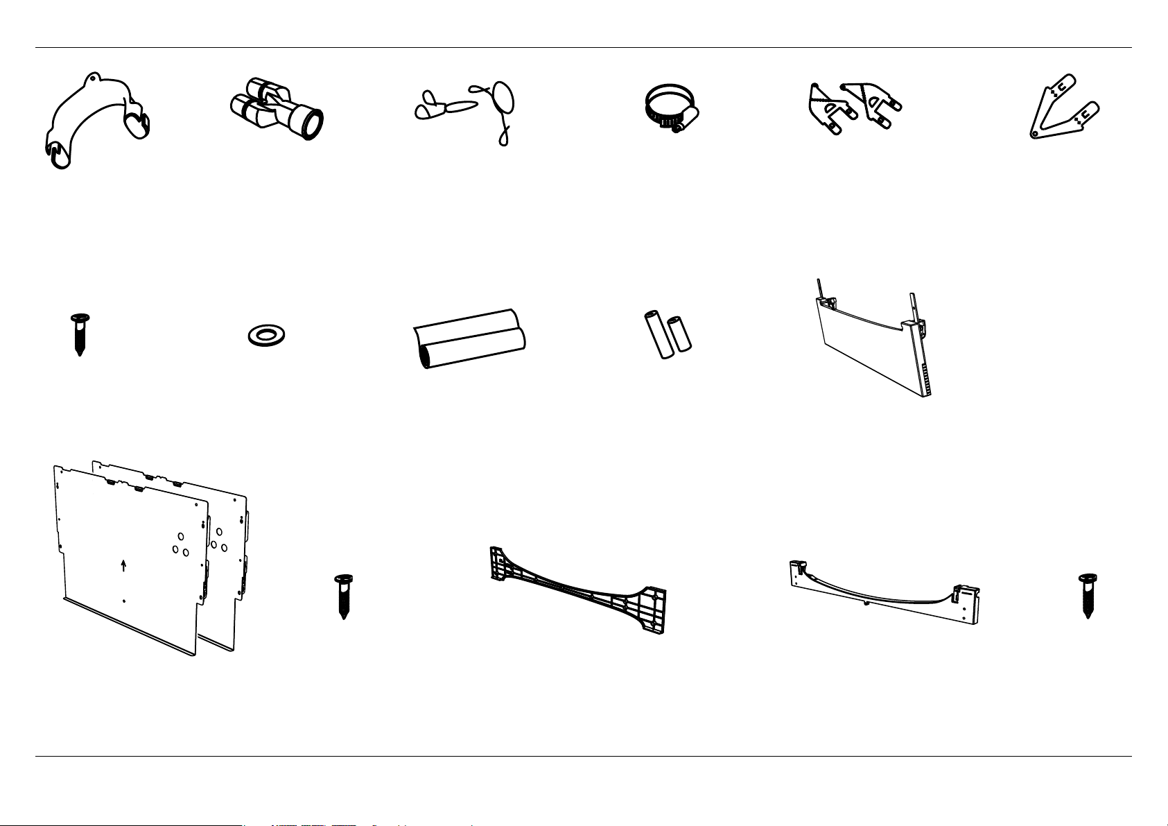
2 PARTS SUPPLIED
Drain hose
support (1)
Phillips
16 mm
screws (9)
Drain hose
joiner (1)
for inlet hose (1)
(comes already
fitted)
Wire clip (2)
(for securing
Drain hose joiner)
Moisture protection
tape (1)
(to prevent moisture
damage to cabinetry)
Clamp (1)
(for securing
Drain hose joiner)
Hexagonal
socket for feet
adjustment (2)
(long & short)
Side mounting
bracket kit
(A and B) (2)
OPTIONAL
Prefinished toekick (1) Rubber washer
Top
mounting
brackets (2)
OPTIONAL
Panel bracket (2)
& Knock-to-Pause Module (2)
(shipped fixed to product)
If the Drain hoses supplied are not long enough to reach your services, you must use a Drain Hose Extension Kit P/N 525798 which will extend the drain hoses by 3.6 m.
The kit is available from the nearest Fisher & Paykel Authorised Service Centre or our website.
Panel mounting
screws (12)
Toekick panel cutting template (1)
(To enable a custom toekick panel to be
cut to fit the product profile dependant
on the depth of the toekick )
Toekick mounting bracket (1)
(A custom toekick panel of any material
with thickness 9 - 19mm can be screwed
to the Toekick mounting bracket)
Toekick
mounting
screws (5)
4
B
D
N
E
A
G
H
I
J
C
F
M
L
K
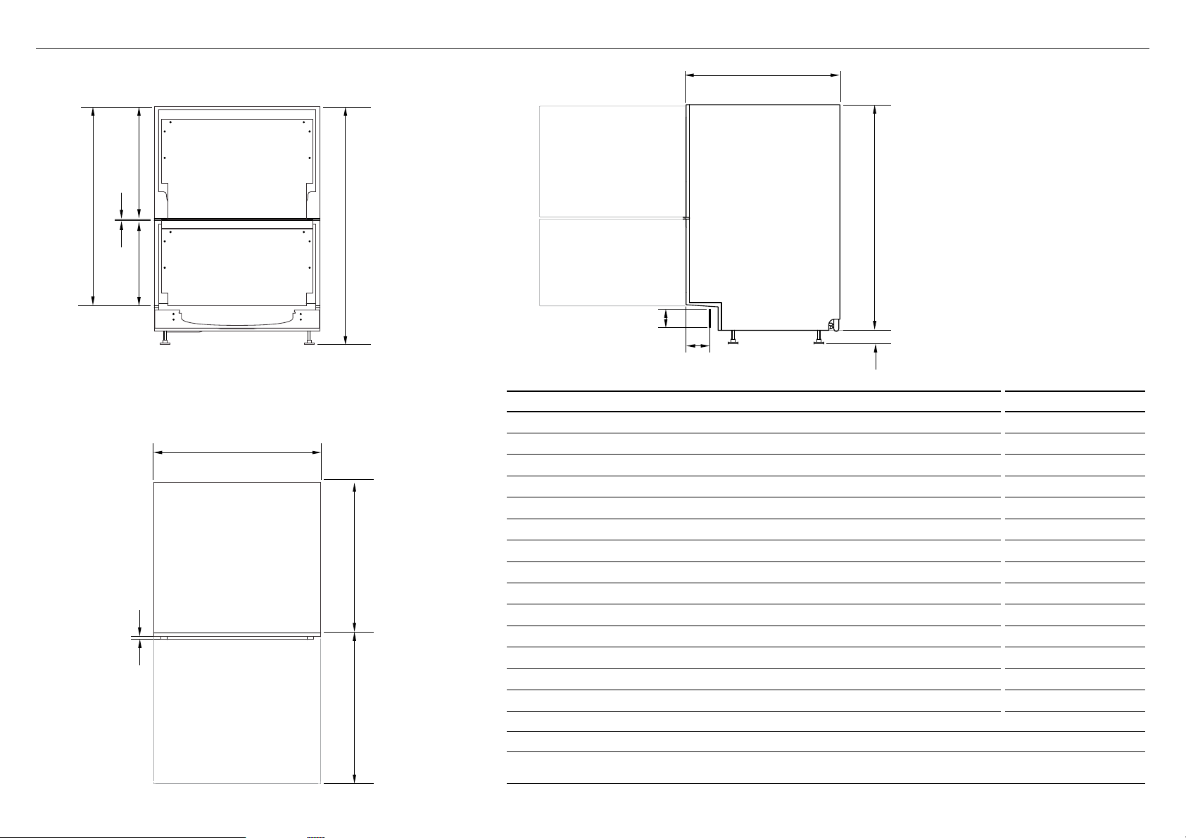
3 PRODUCT DIMENSIONS
PRODUCT DIMENSIONS MM
Overall height of product
A
Overall width of product
B
Overall depth of product
C
Depth of chassis (to back of front drawer panel)
D
Depth of drawer front panel
E
Height of chassis
F
Height of drawer front panels
G
Height of upper drawer front panel
H
Height of lower drawer front panel
I
Ventilation gap between drawer front panels
J
Height of toekick (customisable)
K
Depth from front of drawer panel to front of toekick (adjustable)
L
Height of leveling feet (adjustable)
M
Maximum extension of drawer
N
1
includes 2mm high bracket slots 2 depending on adjustment of leveling feet 3 assuming front panel thickness of 18mm
4
adjustable to match toekick recess on adjoining cabinetry
5
assuming custom toekick panel thickness of 18mm; if recess is between 50-84mm deep, the panel will need to be cut out
- see step ‘Custom panel calculations’
1, 2
3
1
3
PROFILEFRONT
2
4, 5
DD60DI
DD60DHI
820-880
599
571
553
16-20
811
min. 717
min. 398
311-360
58-118
40-100
9-69
545
8
5
PLAN
Q
P
O
R
S
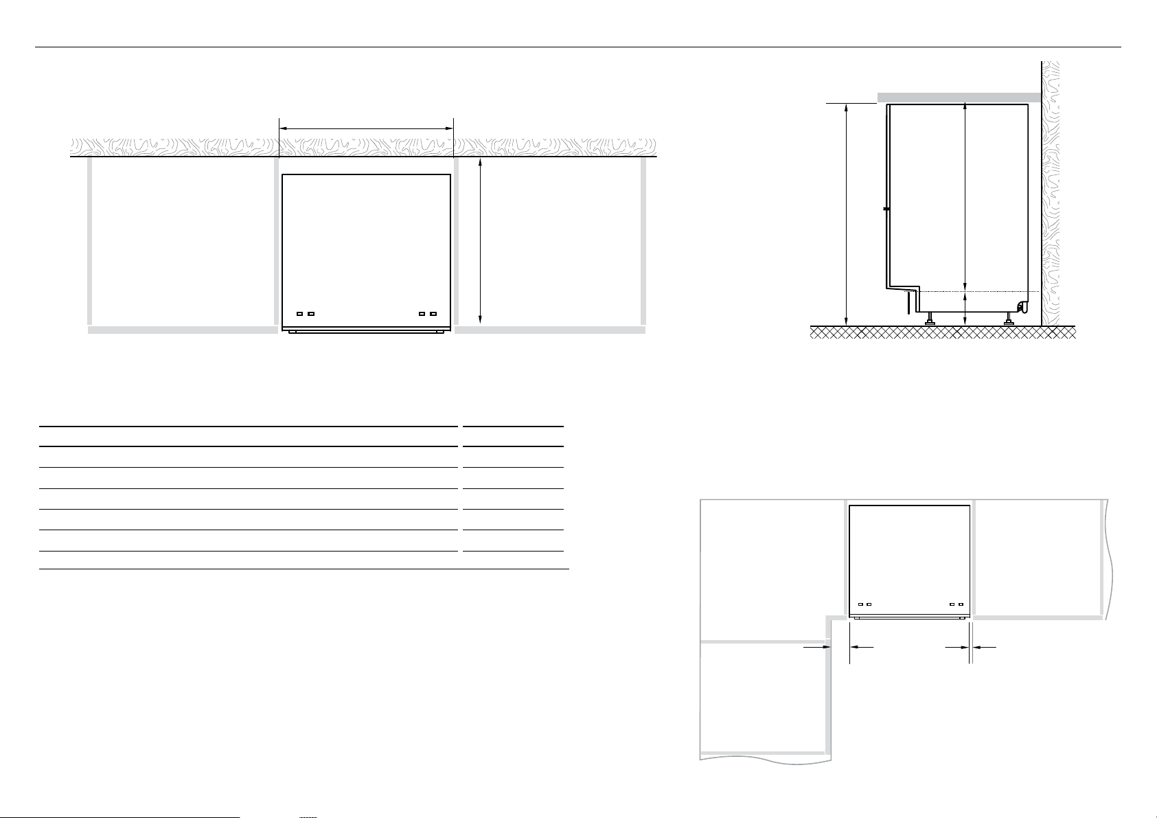
4 CABINETRY DIMENSIONS
Bracket slots
DD60DI
DD60DHI
CABINETRY DIMENSIONS MM
Inside height of cavity* min. 820
O
Inside width of cavity 600
P
Inside depth of cavity min. 560
Q
Recommended height of adjacent cabinet space 720
R
Height of toekick space* 100-160
S
* depending on adjustment of levelling feet
PROFILEPLAN
Minimum clearances from adjacent cabinetry
min. 13 mm
clearance
from a corner
cupboard
min. 2 mm
clearance
to adjacent
cupboard door
6
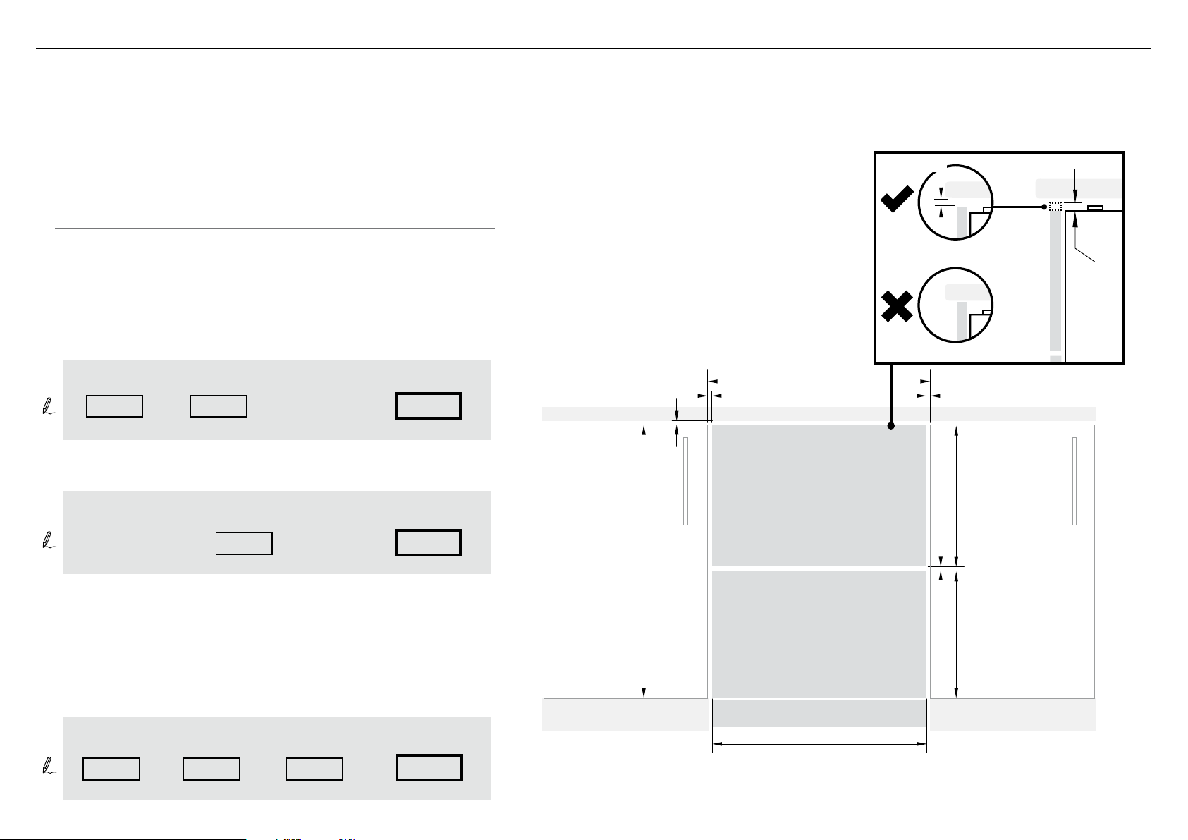
5 CUSTOM DRAWER PANEL CALCULATIONS
FRONT PANEL MATERIAL SPECIFICATIONS
●
16 - 20mm panel thickness
●
Adequately sealed to withstand moisture (50OC @ 80% RH)
Because of it being a hot and wet environment generally, the back and sides of the
panel should be completely sealed with a waterproof vapour barrier (ie polyurethane)
to prevent damage to the panel.
●
The back of the panel (including any integrated handle) should be completely flush
so that the seal between the panel and the rubber trim is maintained.
●
Installation outside these specs may result in condensation on cabinetry surfaces.
●
Maximum weight of each panel: 9kg
The following calculations assume the top of the upper panel is
aligned with the top of the adjacent cabinetry.
The final panel/cabinetry alignment is achieved by adjusting the feet:
WIDTH OF ALL PANELS
Measure A (the width between adjacent door/drawer fronts)
and write it in the first box below, then complete the equation.
Note: The ‘upper panel extension’ B
allows for the top of the upper panel to
extend above the chassis where required,
however a min. 2mm gap to
the benchtop must be maintained.
min. 2mm
B
Clearance to adjacent
A
cabinet front
WIDTH OF PANEL
- 2x =
(min. 2mm)
HEIGHT OF THE UPPER PANEL
minimum
height
398mm
Note: The ‘upper panel extension’ B allows for the top of the upper
panel to extend above the chassis where required, however a
min. 2mm gap to the benchtop must be maintained.
HEIGHT OF THE LOWER PANEL
Measure C (door/drawer height (or equivalent)) and write it in the
first box below, then complete the equation.
C
Upper Panel extension
+
(0mm recommended)
Height of
Upper Panel
--
(min 717mm + B)
7
B
=
Ventilation Gap
=
(min. 8mm)
(596 - 615mm)
HEIGHT OF
UPPER PANEL
HEIGHT OF
LOWER PANEL
(min. 311mm)
min. 2mm
min. 2mm
C
A
UPPER PANEL
LOWER PANEL
TOEKICK PANEL
WIDTH OF ALL PANELS
min. 2mm
HEIGHT OF
UPPER PANEL
Ventilation Gap (min. 8mm)
HEIGHT OF
LOWER PANEL
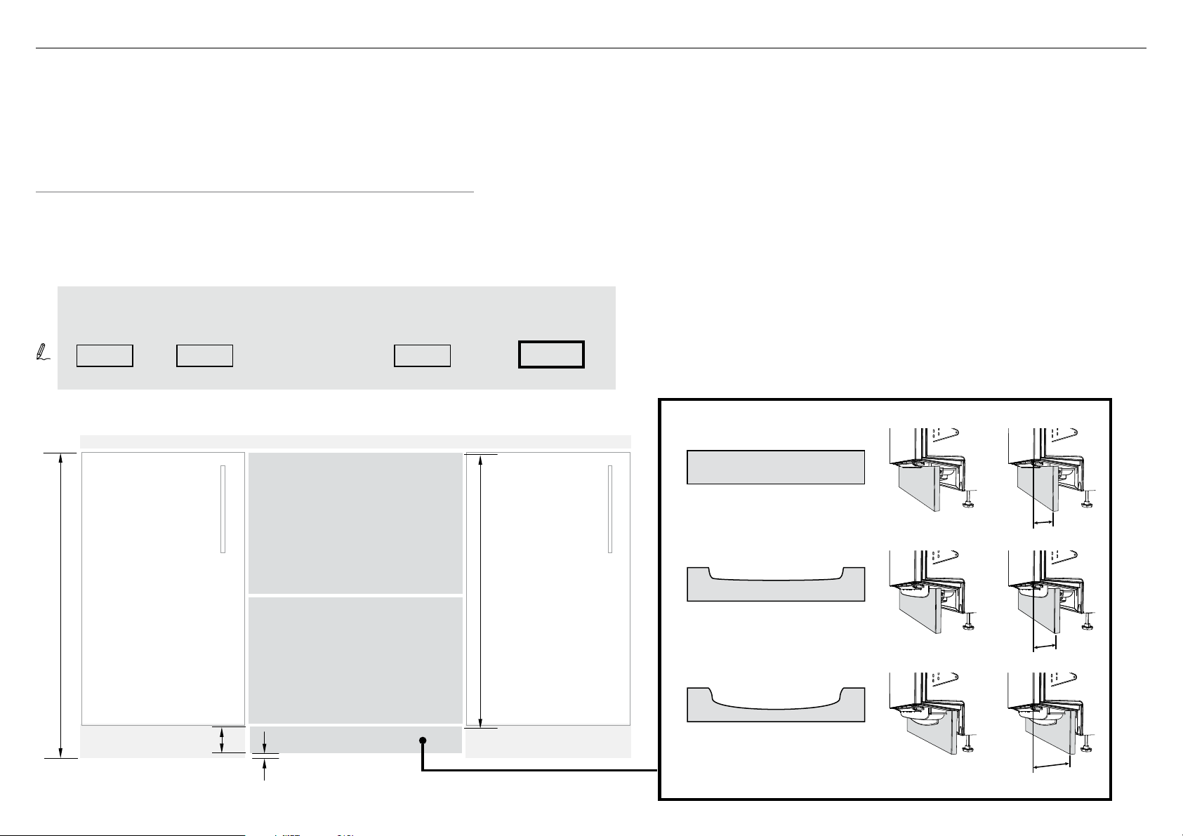
6 CUSTOM TOEKICK PANEL CALCULATIONS
TOEKICK PANEL MATERIAL SPECIFICATIONS
●
min. 9mm panel thickness if using supplied screws
●
Adequately sealed to withstand moisture (50OC @ 80% RH)
●
You may choose to affix your custom toekick panel either by screwing
it or gluing it to the supplied mounting bracket.
HEIGHT OF THE TOEKICK PANEL
Measure D (height from the top of adjacent cabinet door fronts to the floor)
and write it in the first box below, then complete the equation.
D
B
Upper Panel
extension
(0mm recommended)
height from top
of product to
toekick panel
mounting point
750mm
Clearance to floor
(min. 12mm)
HEIGHT OF
TOEKICK PANEL
=-- -
(min. 58mm)
Toekick Depth
Depth is measured from FRONT of door panel
(assuming thickness ~18mm) to front face of
custom toekick panel
NO CUTOUT
CUSTOM TOEKICK PANEL
For a Toekick Depth 40mm
Height from top
of product to
toekick panel
mounting point
750mm
Toekick panel cutting template:
PROFILE A
CUSTOM TOEKICK PANEL
40mm
D
For a Toekick Depth 40-88mm
Toekick panel cutting template:
PROFILE B
40-88mm
HEIGHT OF
TOEKICK PANEL
Clearance to floor
(min. 12mm)
CUSTOM TOEKICK PANEL
For a Toekick Depth 88-100mm
88-100mm
8
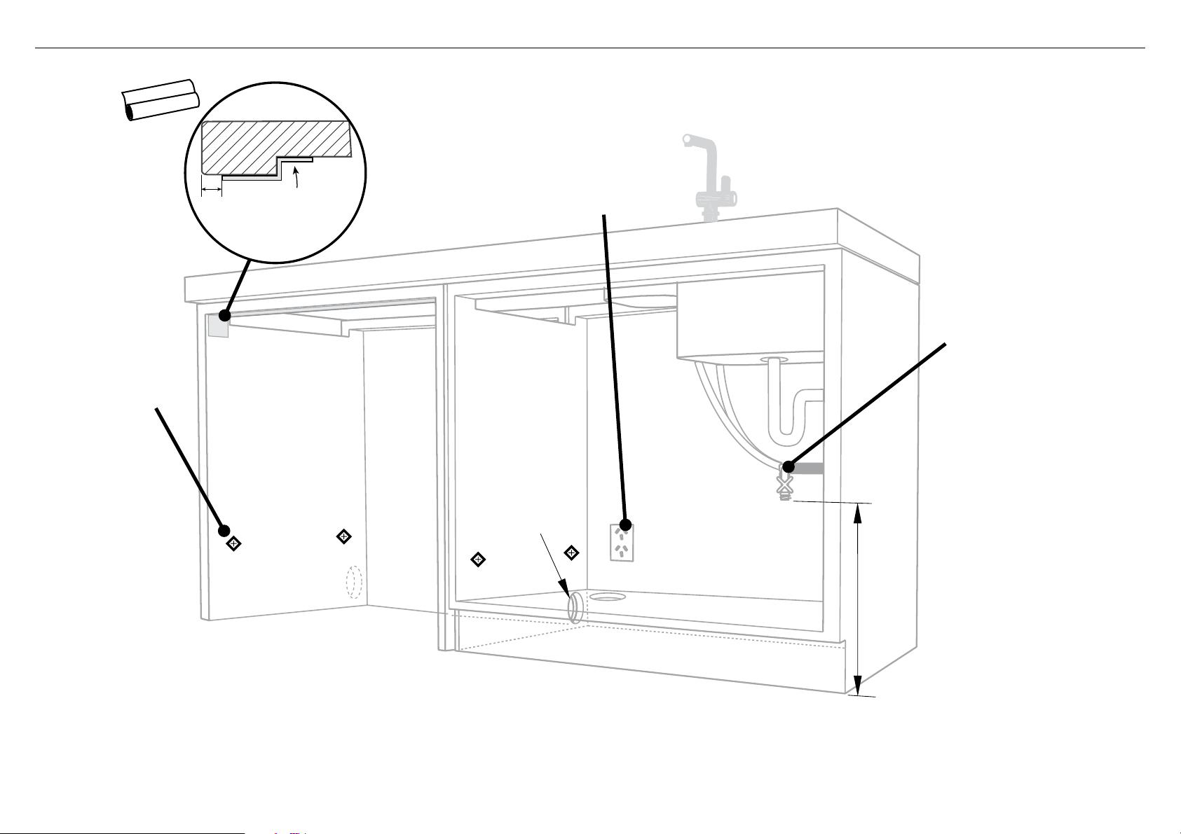
7 CAVITY PREPARATION
These marks indicate
formed bracket screw
locations, if securing by
drawer removal.
10 mm
BENCHTOP
Moisture
protection
tape must
be applied.
IMPORTANT!
The power outlet
must be located in a
cabinet adjacent to the
dishwasher cavity.
220-240 VAC min. 9.5 A
ø 60 mm
Water Connection
Recommended COLD
(Maximum 60°C).
3/4“ BSP (GB20) to
suit flat washer.
Water Pressure
Water softener models
Max. 1 MPa (145 psi)
Min. 0.1 MPa (14.5 psi)
Models without water softener
Max. 1 MPa (145 psi)
Min. 0.03 MPa (4.3 psi)
Kosher requirements
Drains will need to be
separated to satisfy
kosher requirements.
We suggest you confirm
acceptability with your
local rabbi in respect to
Services can be
located either side of
dishwasher.
min. 200 mm
kosher installations.
9
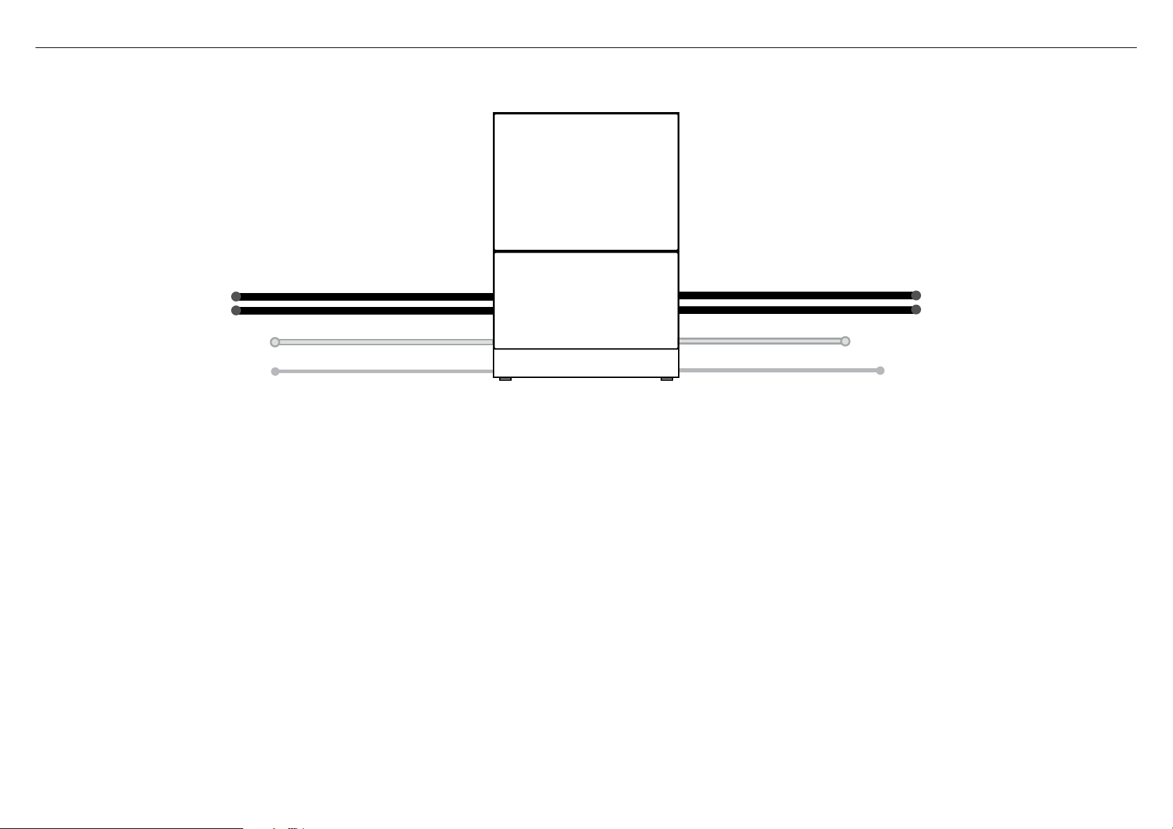
8 MAXIMUM DISTANCE OF HOSES & CORD FROM CHASSIS EDGE
LEFT HAND SIDE
Drain hoses - 2000mm Drain hoses - 1800mm
Inlet hose - 1650mm Inlet hose - 1250mm
Power cord (excl.plug) - 1650mm Power cord (excl.plug) - 1650mm
RIGHT HAND SIDE
10
NOW CHOOSE WHICH INSTALLATION METHOD (A) OR (B)
IS MORE SUITABLE FOR YOUR CABINETRY...
9 RECOMMENDED METHOD (A) - SECURE WITHOUT DRAWER REMOVAL (FRAMELESS CABINETRY ONLY)
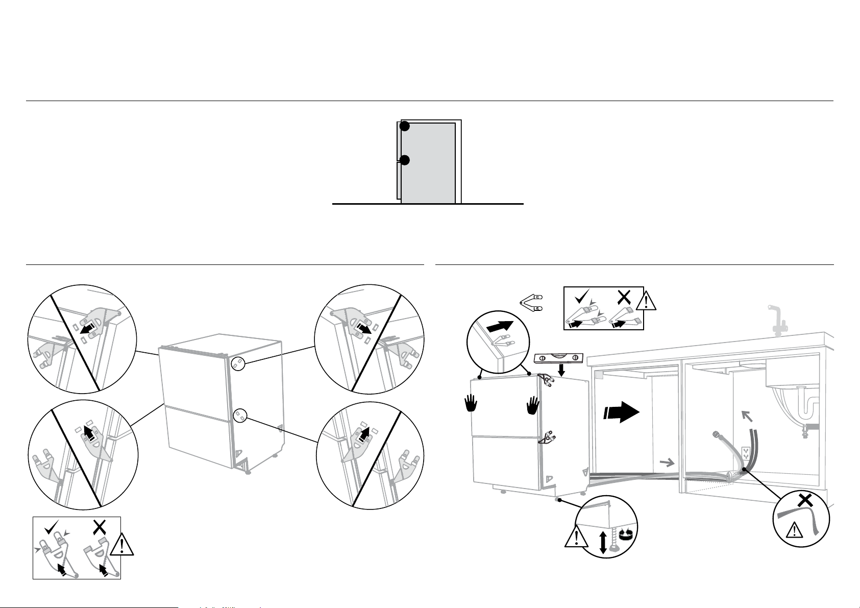
9-A ATTACH SIDE MOUNTING BRACKETS !0-A PULL THROUGH HOSES & PUSH INTO THE CAVITY
Clip all four side mounting brackets
into their slots using a flat-bladed
screwdriver. Ensure they’re securely
fitted before sliding product into cavity.
AB
optionally attach the
two top mounting
brackets
(x2)
Initially level the product
When fitting brackets,
ensure the ends are
not pushed down into
the chassis.
B
A
A
B
A
The mounting slots are in pairs, one on
each side diagonally across the product.
A bracket must match A slot and B
bracket must match B slot.
When fitting brackets, ensure the
ends are not pushed down into
the chassis.
11
B
You can raise or lower
the product by twisting
the feet. Then take
care when pushing the
product into the cavity
that you do not bend the
feet.
As you push product
in, pull through hoses
and cord, ensuring
they don’t get kinked
or twisted.
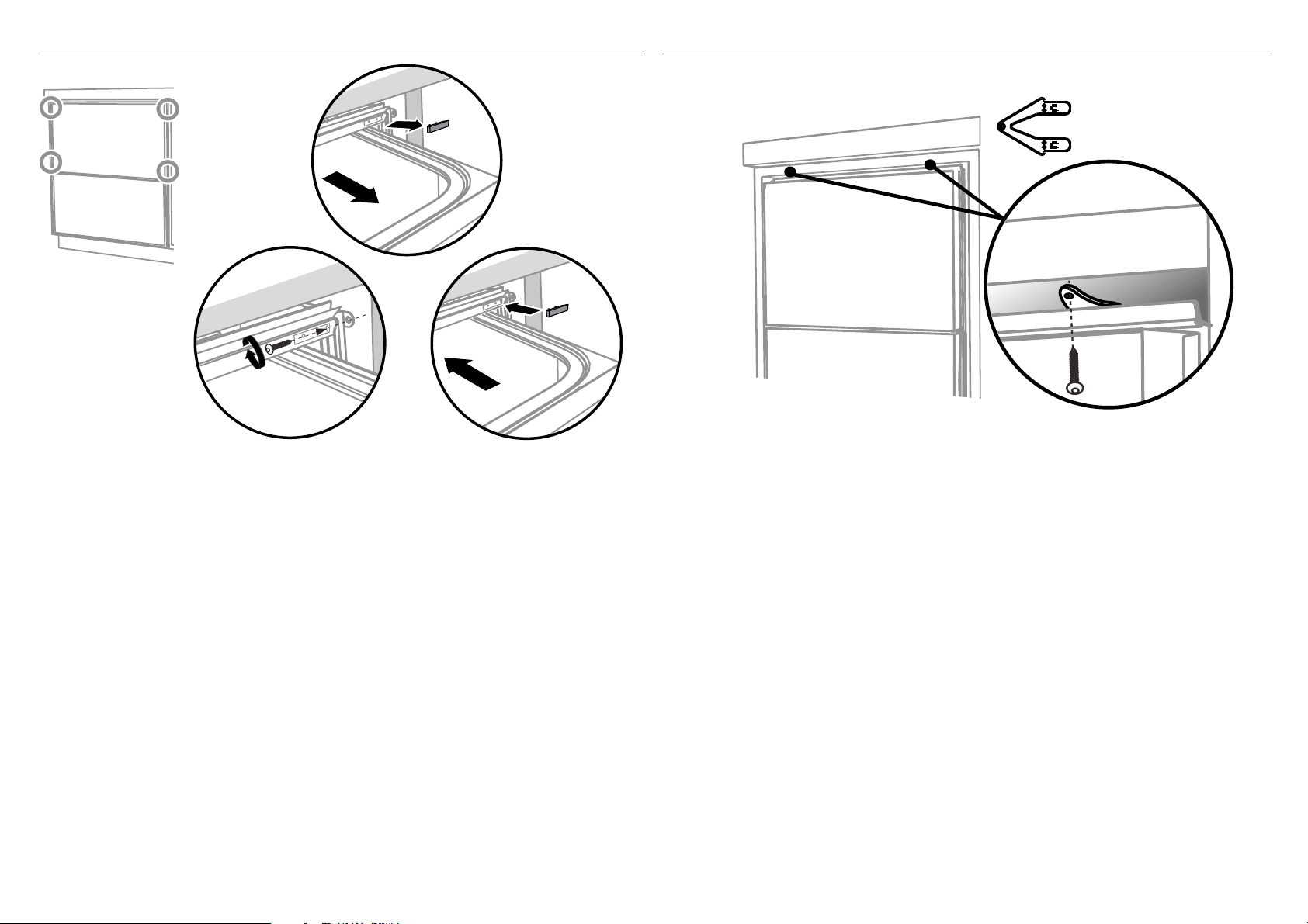
!1-A SECURE TO THE CABINETRY ON THE SIDES
!2-A OPTIONALLY SECURE TO THE CABINETRY ABOVE
Using a small
Philips screwdriver,
screw through the
trim moulding,
securing the side
mounting bracket
to the cabinetry.
Do not damage
the rubber
trimseal.
Open the
drawer halfway.
Using a flat
bladed
screwdriver,
prise the grey
rubber plug out
of the trim
moulding.
2
Repeat for all
four brackets.
1
Replace the grey
rubber plug back into
the trim moulding
and ensure the trim
seal is facing forward.
The top mounting
brackets will only
(x2)
bend upwards a
maximum of 10mm.
3
!3-A AFTER SECURING, REFER TO ‘FIT THE SUPPLIED TOEKICK PANEL’ STEP
12
9 ALTERNATIVE METHOD (B) - SECURE BY DRAWER REMOVAL
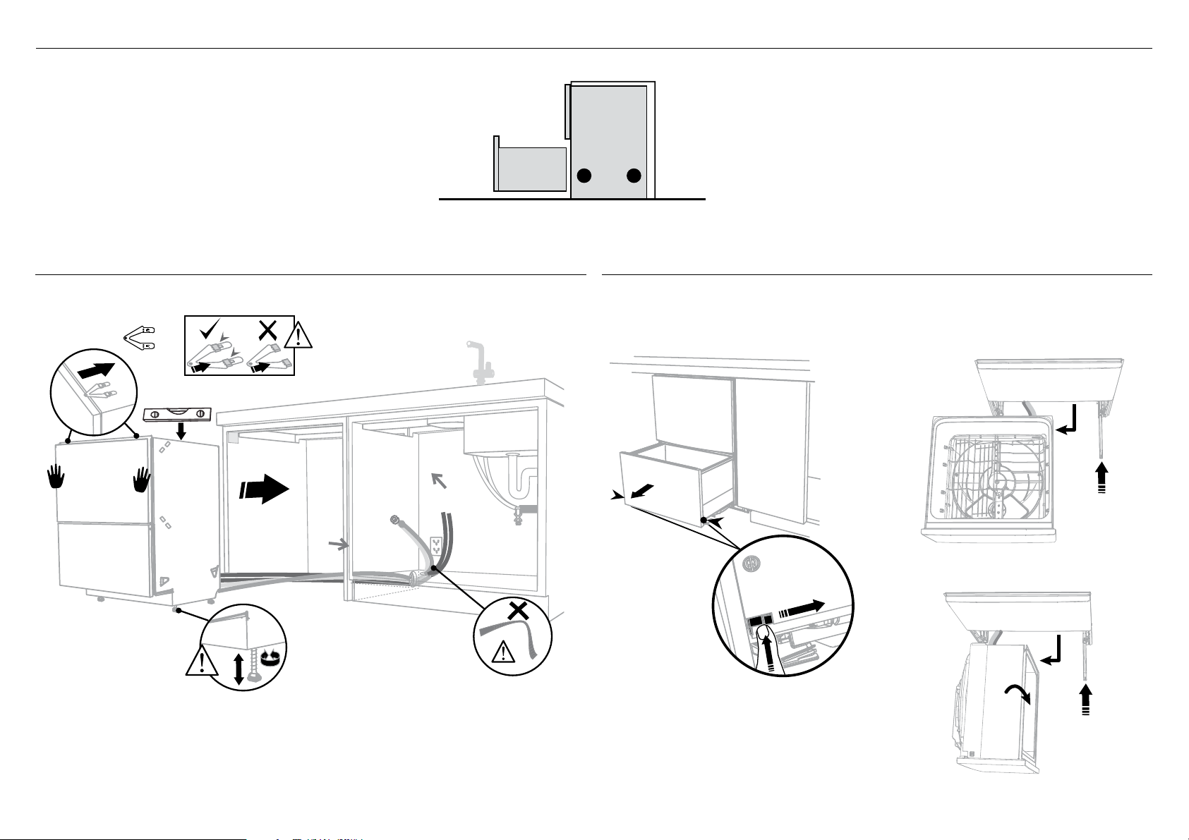
9-B PULL THROUGH HOSES & PUSH INTO THE CAVITY !0-B REMOVE THE LOWER DRAWER
optionally attach the
two top mounting
brackets
(x2)
Initially level the product
You can raise or lower
the product by twisting
the feet. Then take
care when pushing the
product into the cavity
that you do not bend the
feet.
13
When fitting brackets,
ensure the ends are
not pushed down into
the chassis.
As you push product
in, pull through hoses
and cord, ensuring
they don’t get kinked
or twisted.
1
2
100 mm
Press the release tabs
in on either side and
push back to release
drawer from runners.
Lift drawer off runners.
To prevent kinked hoses
Either sit the drawer down on the left
hand side (recommended) or rotate the
drawer clockwise, resting it on its side after
removal.
3
4
Push drawer
runners back in
Sit the drawer down
on either side.
3
4
Push drawer
Rotate the drawer
clockwise (max. 90
and rest on side.
o
)
runners back in
on either side.
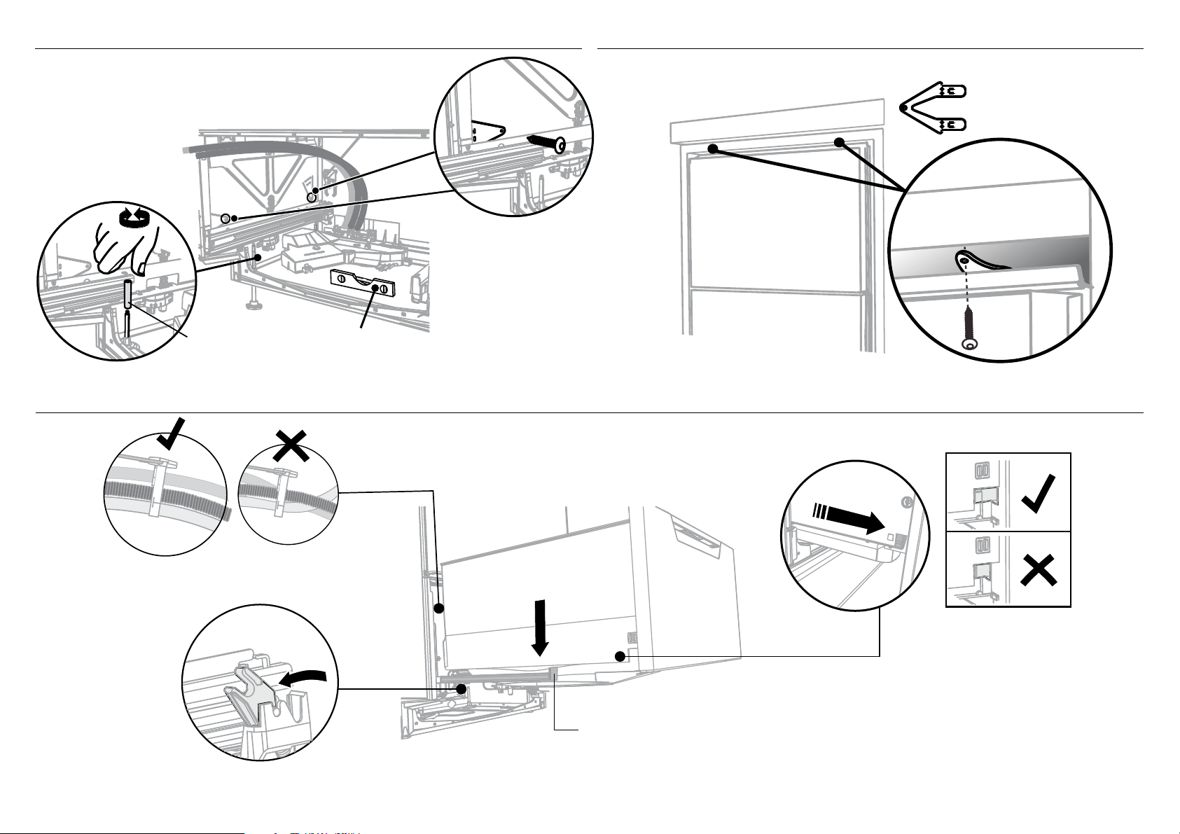
!1-B SECURE TO THE CABINETRY ON THE SIDES !2-B OPTIONALLY SECURE TO THE CABINETRY ABOVE
For further adjustment,
using the most appropriate
length Hexagonal socket
supplied, fully extend
levelling feet up to
required distance by hand.
Secure using two pairs
of formed brackets.
Repeat on the other
side of the chassis.
(x2)
The top mounting
brackets will only
bend upwards a
maximum of 10 mm.
x4
Before refitting the
drawer, ensure the hoses
are not twisted and the
latches at the rear of
each drawer runner are
facing forward.
Hexagonal
socket
2
Ensure product is level and
aligning with cabinetry.
1
!3-B REFIT THE DRAWER ONTO THE RUNNERS
Lift or rotate anti-clockwise the
drawer back onto the drawer runners
on either side.
3
Release tab
4
100 mm
Pull the release tabs forward on both
sides 100 mm. Ensure the tabs are fully
pulled forward and click into place.
14
 Loading...