

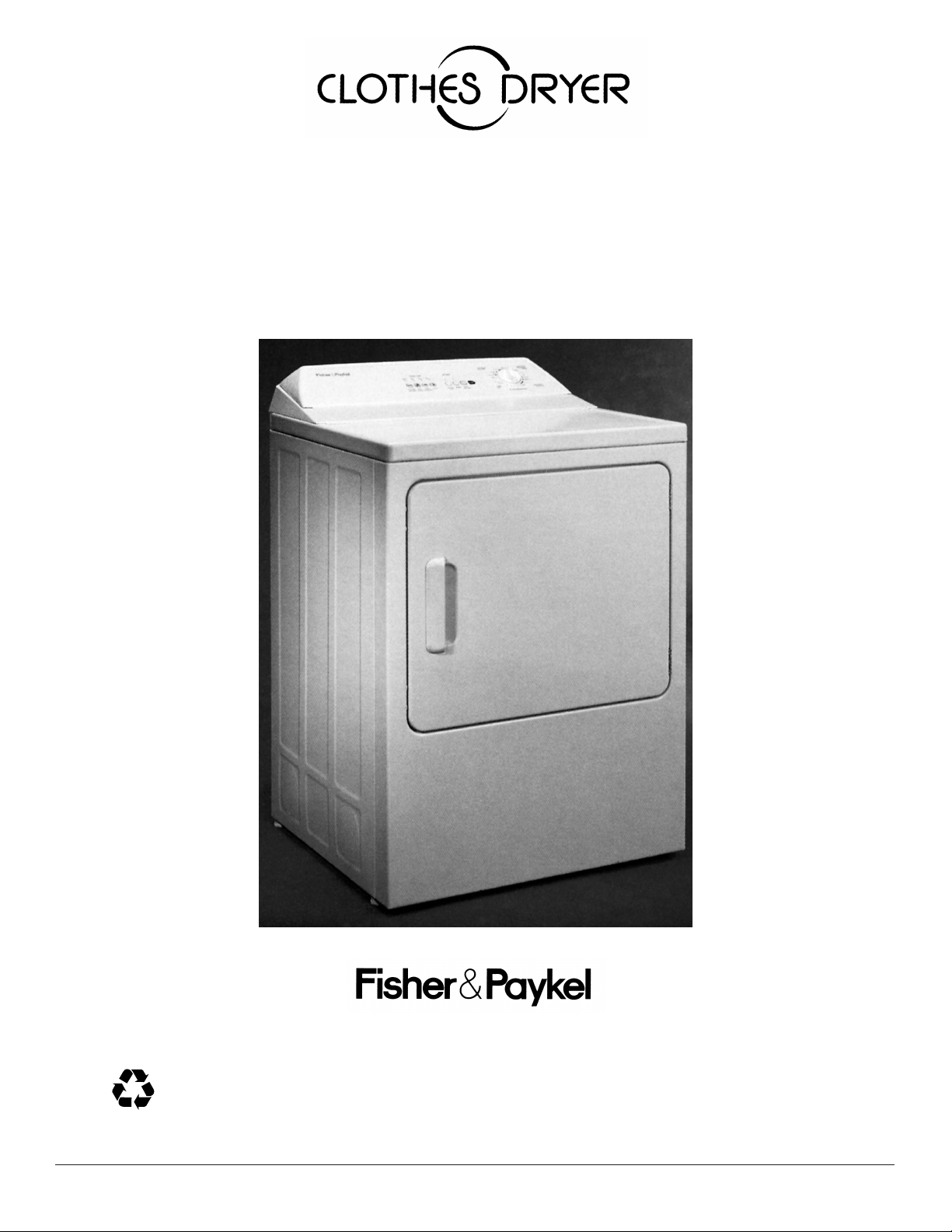
Use and Care
With Installation Instructions
RECYCLED PAPER
RECYCLABLE
We care about our environment
500A277P046
Safety Instructions ................... 3, 4
Installation Instructions
Exhaust.........................................................6, 7
Electric Dryer ...................................................8
Gas Dryer .....................................................8, 9
Reversible Door Instructions .......................5
Care and Cleaning
Dryer Exhaust ...............................................14
Exterior ...........................................................11
Light Bulb Replacement.............................13
Lint Filter ........................................................11
Problem Solver ............................. 15
Operating Instructions, Tips
Automatic Drying ........................................13
Drying Selection Guide .......................12, 13
Electronic Sensor Control..........................13
Extra Care Program..............................10, 12
Knits Drying Tips ..................................11, 12
Lint Filter ........................................................11
Loading ...................................................11, 15
Operating the Dryer ..............10, 11, 12, 13
Permanent Press
Drying Tips .........................................11, 15
Sorting Clothes .....................................11, 12
Special Instructions.....................................12
Timed Drying.........................................12, 13
End Cycle Signal ..........................................10
Read this book carefully.
It is intended to help you operate and
maintain your new dryer properly.
Keep it handy for answers to your
questions.
If you don’t understand something or
need more help, write (include your
phone number)
Consumer Relations Manager
Camco Inc.
1 Factory Lane, Suite 310
Moncton, N.B. E1C 9M3
Consumer Services
Model and Serial Numbers ..........................2
Repair Service .................................................2
Warranty ........................................................16
Save time and money.
Before you request service...
check the Problem Solver section, it
lists causes of minor operating
problems that you can correct
yourself.
If you received a
damaged dryer...
Immediately contact the dealer (or
builder) that sold you the dryer.
Write down the model
and serial numbers.
You’ll find them on a label on the
front of the dryer behind the door.
These numbers are also on the
Consumer Product Ownership
Registration Card that came with
your dryer. Before sending in this
card, please write these numbers
here:
Model Number
Serial Number
Use these numbers in any
correspondence or service calls
concerning your dryer.
WARNING: For your safety the information in this manual must be followed to minimize the
risk of fire or explosion or to prevent property damage, personal injury or death.
– Do not store or use gasoline or other
flammable vapors and liquids in the vicinity
of this or any other appliance.
– WHAT TO DO IF YOU SMELL GAS
• Do not try to light any appliance.
• Do not touch any electrical switch;
do not use any phone in your building.
• Clear the room, building or area of all
• Immediately call your gas supplier from a
neighbor’s phone. Follow the gas supplier’s
instructions.
• If you cannot reach your gas supplier, call
the fire department.
– Installation and service must be performed
by a qualified installer, service agency, or the
gas supplier.
occupants.
2
IMPORTANT SAFETY INSTRUCTIONS
Read all instructions before using this appliance
Warning - It is extremely important that you read and adhere to the
following instructions. Failure to do so could cause bodily injuries
and / or property damage due to fire.
• Use this appliance only for its intended purpose
as described in this Use and Care Book.
This dryer must be properly installed
and located in accordance with the
Installation Instructions before it is used.
– Properly ground to conform with Local Codes.
Follow details in Installation Instructions.
– Locate where the temperature is above 50˚F.
(10˚C.) for satisfactory operation of the dryer
control system. Do not install or store the dryer
where it will be exposed to the weather.
– Connect to a properly rated, protected and sized
power supply circuit to avoid electrical overload.
– Exhausting to the outside is STRONGLY
RECOMMENDED to prevent large amounts of
moisture and lint from being blown into the room.
Carefully follow the Exhausting Details in the
Installation Instructions.
Do not repair or replace any part of the
appliance or attempt any servicing
unless specifically recommended in this
Use and Care Book or in published user-repair
instructions that you understand and have the
skills to carry out.
When disconnecting this appliance
pull by the plug rather than the cord
to avoid damage to the cord or junction
of cord and plug. Make sure that the cord
is located so that it will not be stepped on, tripped
over or otherwise subjected to damage or stress.
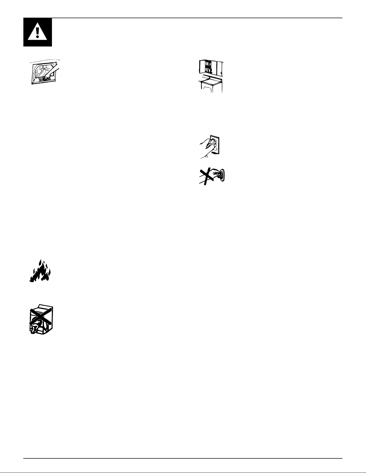
To Minimize the Possibility of a
Fire Hazard
• Exhaust Duct – See Installation Instructions. Use
only rigid metal or flexible metal 4” diameter
ductwork for exhausting to the outside. USE OF
PLASTIC OR OTHER COMBUSTIBLE
DUCTWORK CAN CAUSE A FIRE. FOIL OR
OTHER EASILY PUNCTURED DUCTWORK
CAN CAUSE A FIRE IF IT COLLAPSES OR
BECOMES OTHERWISE RESTRICTED IN USE
OR DURING INSTALLATION.
• Do not use heat to dry articles containing rubber,
plastic, or similar materials (such as padded bras,
tennis shoes, galoshes, bath mats, rugs, bibs, pillows,
baby pants, plastic bags, etc.) as these materials may
melt or burn. Also, some rubber materials, when
heated, can under certain circumstances produce fire
by spontaneous combustion.
• Do not store items that may burn or melt (such as
clothing, paper material, plastics or plastic
containers, etc.) on top of the dryer during the
operation.
• Garments labeled “Dry Away from Heat” (such
as life jackets containing Kapok or foam) must
not be put in your dryer.
• Do not wash or dry articles that
have been cleaned in, washed in,
soaked in, or spotted with combustible
or explosive substances (such as wax,
paint, gasoline degreasers, dry-
cleaning solvents, kerosene, etc.) which may ignite
or explode. Do not add these substances to the
wash water. Do not use these substances around
your washer and/or dryer during operation.
• Any article on which you have used a cleaning
solvent, or which contains flammable materials (such
as cleaning cloths, mops, towels used in beauty
salons, restaurants or barber shops, etc.) must not be
placed in or near the dryer until all traces of these
flammable liquids or solids and their fumes have
been removed. There are many highly flammable
items used in homes such as: acetone, denatured
alcohol, gasoline, kerosene, some household
cleaners, some spot removers, turpentines, waxes,
wax removers and products containing petroleum
distillates.
(continued on next page)
Important Safety Instructions
3
IMPORTANT SAFETY INSTRUCTIONS
•Clean the lint filter before each load
to prevent lint accumulation inside
the dryer or in the room.
DO NOT OPERATE THE DRYER
WITHOUT THE LINT FILTER IN
PLACE.
• Keep the area around and underneath your
appliances free from the accumulation of
combustible materials, such as lint, paper, rags,
chemicals, etc.
• Regularly inspect the exhaust duct to be sure it
has not been crushed or otherwise restricted.
• The interior of the dryer cabinet and the exhaust
duct connection inside the dryer should be cleaned
every 2 to 3 years, or more often if needed, by a
qualified service person. (see Care & Cleaning
section)
To Minimize the Possibility of Injury
• Never reach into the dryer while the drum is
moving. Before loading, unloading or adding clothes,
wait until the drum has completely stopped.
• Do not dry fiberglass articles in your dryer. Skin
irritation could result from the remaining glass
particles that may be picked up by clothing during
subsequent dryer uses.
• The laundry process can reduce the
flame retardance of fabrics. To avoid
such a result, the garment manufacturer’s
care instructions should be followed very
carefully.
• Close supervision is necessary if this
appliance is used by or near children.
Do not allow children to play inside,
on, or with this appliance or any
discarded appliance. Dispose of
discarded appliances and shipping or
packing materials properly. Before discarding a
dryer, or removing from service, remove the door
of the dryer compartment.
SAVE THESE
INSTRUCTIONS
• Keep all laundry aids (such as
detergents, bleaches, fabric softeners,
etc.) out of the reach of children,
preferably in a locked cabinet. Observe
all warnings on container labels to avoid
personal injury.
• Keep the floor around your appliances clean and
dry to reduce the possibility of slipping.
• To minimize the possibility of electric shock,
unplug this appliance from the power
supply before attempting any maintenance
or cleaning (except the removal and
cleaning of the lint filter).
• NOTE: Turning the Cycle Selector
knob to an OFF position does NOT
disconnect the appliance from the power
supply.
• Do not tamper with the controls.
• Do not operate this appliance if it is damaged,
malfunctioning, partially disassembled, or has
missing or broken parts, including a damaged
cord or plug.
• Never climb on or stand on the dryer top.
• DO NOT place items exposed to cooking oils in
your dryer. Items contaminated with cooking oils
may contribute to a chemical reaction that could
cause a clothes load to catch fire.
• If yours is a gas dryer, it is equipped with an
automatic electric ignition and does not have a
pilot light. DO NOT ATTEMPT TO LIGHT WITH A
MATCH. Burns may result from having your hand in
the vicinity of the burner when the automatic ignition
may turn on.
Dryer-applied Fabric Softeners or
Anti-static Conditioners
You may wish to soften your laundered fabrics or
reduce the static electricity in them. We recommend
you use either a fabric softener in the wash cycle,
according to the manufacturer’s instructions for those
products, or try a dryer-added product for which the
manufacturer gives written assurance on the package
that their product can be safely used in your dryer.
Service or performance problems caused by the use of
these products are the responsibility of the
manufacturers of those products and are not covered
under the warranty of this appliance.
4

REVERSIBLE DOOR INSTRUCTIONS
These instructions are for changing the hinges from the
right side to the left side.
Tools Needed
Standard #2 Phillips screwdriver
DRYER DOOR
1. Open the door and remove the filler plugs opposite the
hinges.
(A tape-tipped putty knife
or a needle-nosed plier
will help to remove the
plugs. Be careful not to
damage the paint.)
2. With the door completely
open, remove the bottom
screw attaching each hinge
to the dryer front. (Do not
remove the screws located
on the door itself).
If you need to change the hinges from the left side to
the right side, follow these same instructions (merely
reverse all references to the left and right).
6. Rotate the door 180˚.
Insert it on the opposite
door frame by moving the
door IN and DOWN until
the top hinge and the
bottom hinge are resting on
the top screws inserted in
step 3.
7. With the other screws, secure
each hinge at the bottom.
8. Tighten the top screws of each
hinge.
Reversible Door Instructions
3. Insert these screws about half way into the top holes,
for each hinge, on the opposite side (where you
removed the filler plugs).
4. Loosen the remaining top screw
from each hinge on the dryer front,
half way.
5. With one hand holding
the top of the door, and
the other hand holding
the bottom, remove the
door from the dryer
front by lifting it UP
and OUT.
9. Reinsert the plastic plugs on the side from which the
door was removed.
5
INSTALLATION INSTRUCTIONS
298mm
(11 3/4")
91mm
(3 1/2")
NOTE: ADD TO
91mm (31/2")
THE DISTANCE
BETWEEN
CABINET BOTTOM
TO FLOOR SURFACE
EXHAUST
Installation and service must be performed by a qualified installer, service agency or the gas supplier.
IMPORTANT: Have your dryer installed properly.
NOTE: The WARNING and IMPORTANT instructions appearing in this manual are not meant to cover all
possible conditions and situations that may occur. It must be understood that common sense, caution, and
carefulness are factors that CANNOT be built into the dryer. These factors MUST BE supplied by the person(s)
installing, maintaining, or operating the dryer.
Failure to install, maintain, and/or operate this machine according to the manufacturer’s instructions may result in
conditions which can produce bodily injury and/or property damage.
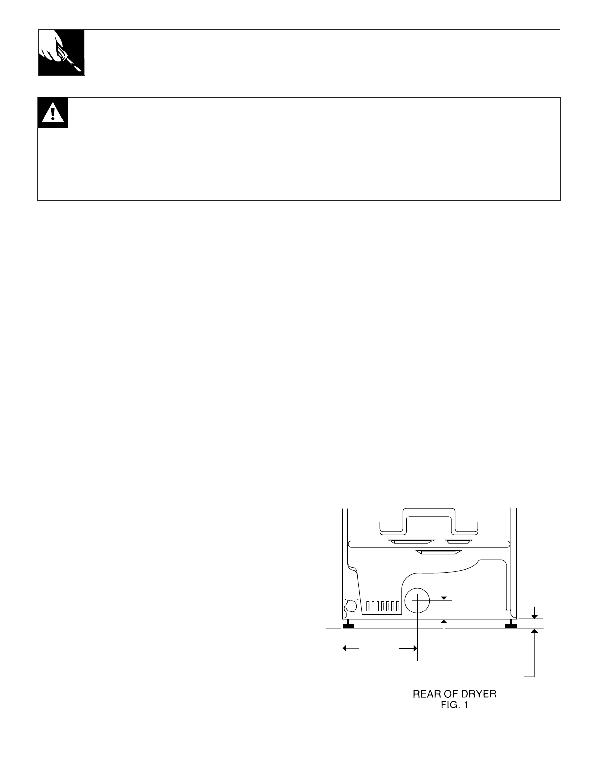
This dryer comes ready for rear exhausting (see Fig. 1).
WARNINGS
• DO NOT USE NON METALLIC FLEXIBLE DUCT.
• Never use flexible duct inside the dryer.
• Do not terminate exhaust in a chimney, range hood,
gas vent, floor or attic. The combination of lint and
grease could create a fire hazard or damages.
• Provide an access for inspection and cleaning the
exhaust system at least once a year. (See Care and
Cleaning Section.)
EXHAUST LENGTH
The MAXIMUM ALLOWABLE length of the exhaust
system depends upon the type of duct, number of turns,
the type of exhaust hood (wall cap), and all conditions
noted below. The maximum allowable length for both
rigid and flexible metal duct is shown in the table 1
(next page). More than four 90˚ turns is not
recommended.
EXHAUST SYSTEM CHECK LIST
HOOD or WALL CAP
• Terminate in a manner to prevent back drafts or entry
of birds or other wildlife.
• Termination should present minimal resistance to the
exhaust air flow and should require little or no
maintenance to prevent clogging.
• Wall caps must be installed at least 300 mm (12”)
above ground level or any other obstruction with the
opening pointed down.
• If roof vents or louvered plenums are used, they must
be equivalent to a 100 mm (4”) dampered wall cap in
regard to resistance to air flow, prevention of back
drafts and maintenance required to prevent clogging.
SEPARATION OF TURNS
Separate all turns by at least 1 m (3 ft.) of straight duct,
including distance between last turn and dampered wall
cap. If two turns must be closer than 1 m (3 ft.) deduct
3 m (10 ft.) from the maximum lengths shown in the
table for each occurrence.
TURNS OTHER THAN 90˚
• One turn of 45˚ or less may be ignored.
• Two 45˚ turns should be treated as one 90˚.
• Each turn over 45˚ should be treated as one 90˚.
SEALING OF JOINTS
• All joints should be tight to avoid leaks. The male
end of each section of duct must point away from the
dryer.
• Do not assemble the duct work with fasteners that
extend into the duct. They will serve as a collection
point for lint.
• Duct joints can be made air and moisture-tight by
wrapping the overlapped joints with duct tape.
INSULATION
• Duct work which runs through an unheated area or is
near an air conditioning duct, should be insulated to
reduce condensation and lint build up and be sloped
down toward outdoors.
NOTE: Never install screen inside exhaust duct.
CAUTION: THE DRYER MUST EXHAUST TO
THE OUTDOORS.
6
INSTALLATION INSTRUCTIONS
EXHAUST
Table 1: RECOMMENDED MAXIMUM LENGTH
ELECTRIC DRYERS GAS DRYERS
Weather Hood Type Weather Hood Type
Recommended
Use only for short
run installations
Recommended
Use only for short
run installations
No. of 90˚
elbows
0
1
2
3
4
* Do not use non metallic flexible duct.
Rigid
27.4 m (90 ft.)
18.3 m (60 ft.)
13.7 m (45 ft.)
10.7 m (35 ft.)
7.6 m (25 ft.)
Metallic
Flexible*
16.8 m (55 ft.)
12.2 m (40 ft.)
9.1 m (30 ft.)
6.1 m (20 ft.)
4.6 m (15 ft.)
Rigid
18.3 m (60 ft.)
13.7 m (45 ft.)
10.7 m ( 35 ft.)
7.6 m (25 ft.)
4.6 m (15 ft.)
13.7 m (45 ft.)
9.1 m (30 ft.)
6.1 m (20 ft.)
4.6 m (15 ft.)
3.0 m (10 ft.)
Metallic
Flexible*
Rigid
13.7 m (45 ft.)
10.7 m (35 ft.)
7.6 m (25 ft.)
4.6 m (15 ft.)
–
Metallic
Flexible*
9.1 m (30 ft.)
6.1 m (20 ft.)
3.0 m (10 ft.)
–
–
Rigid
9.1 m (30 ft.)
6.1 m (20 ft.)
3.0 m (10 ft.)
–
–
Metallic
Flexible*
4.6 m (15 ft.)
3.0 m (10 ft.)
–
–
–
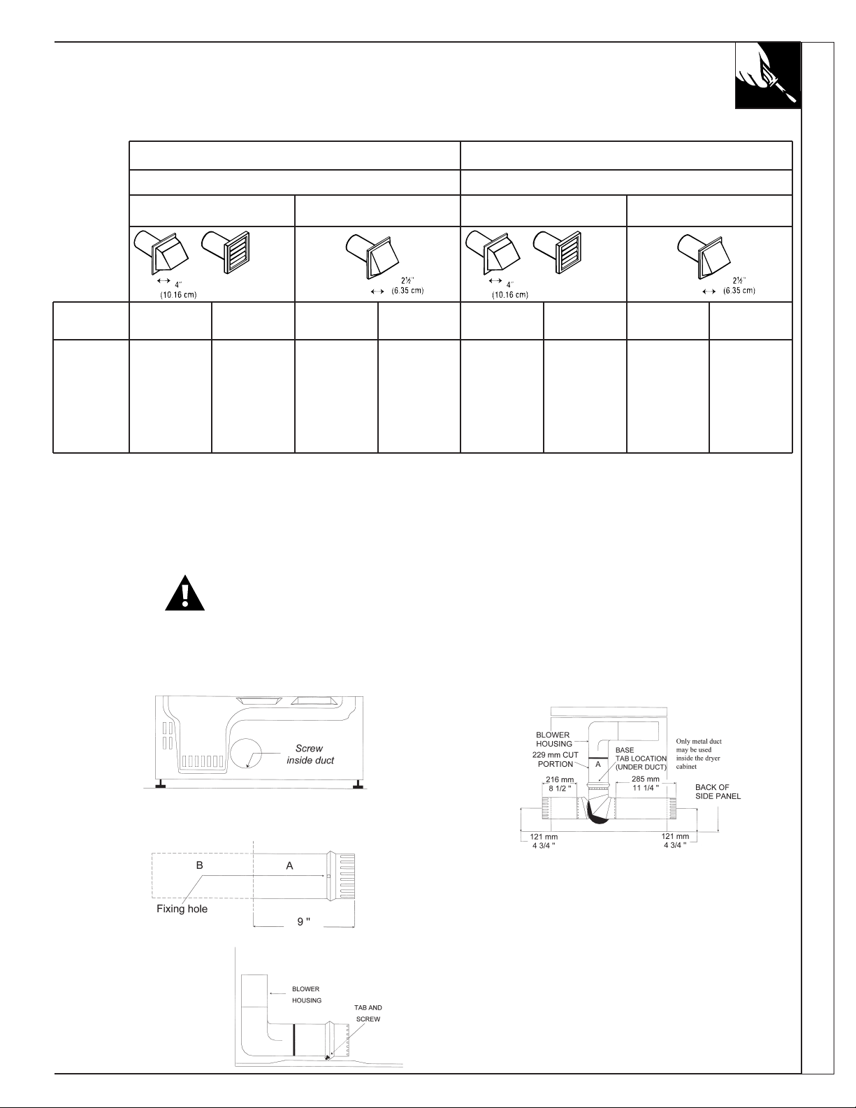
ALTERNATE EXHAUST DIRECTIONS
This dryer comes ready for rear exhausting. If space is limited, use the following instructions to exhaust
directly from the side or bottom of the cabinet.
GAS DRYER CAN NOT BE EXHAUSTED DIRECTLY THROUGH THE RIGHT SIDE OF THE CABINET.
WARNING: Protect your hands and arms when working inside the cabinet.
• Never use flexible duct inside dryer.
• Detach and remove the desired knockout.
• Remove the screw inside the dryer exhaust duct end.
Pull on the duct to remove it. Keep the screw for
later.
• Reconnect and secure the cut portion (A) of the duct
to the blower housing. Make sure that the fixing
hole is aligned with the tab in the base. Use the
reserved screw to secure the duct in place through
the tab on the appliance base.
Installation Instructions
• Cut the duct as shown, 229 mm (9 inches).
Keep portion A.
• Through the rear
opening, locate the
tab in the middle of
the appliance base.
Lift the tab to about
45˚ using a flat
screwdriver.
• Use a standard and ajustable metal elbow and a
metal straight duct to exhaust the dryer through the
knockout choosen. Insert standard elbow and ducts
through rear and side or bottom openings.
• Use only 100 mm (4 inch) diameter rigid metallic
duct.
• Cover the opening at the back with the plate (Kit
WE1M454) available from your Local Service
Provider.
WARNING: Never leave the opening at the back
without the plate.
7
INSTALLATION
4 LEVELING
LEGS
SIDE
VIEW
IMPORTANT - OBSERVE ALL GOVERNING CODES
Dryer must be levelled and rest firmly on the floor.
SPECIAL INSTALLATION REQUIREMENTS
ALCOVE OR CLOSET INSTALLATION
• The dryer MUST be exhausted to the outdoor. See
EXHAUST INFORMATION section.
• Minimum clearances between dryer cabinet and
adjacent walls or other surfaces are:
0 mm (0”) either side
76 mm (3”) front and rear
• Minimum vertical space from floor to overhead
cabinets, ceilings, etc. is 132 cm (52”).
NOTE: CONSIDERATION MUST BE GIVEN TO
INSTALLING AND SERVICING THE APPLIANCE.
• Closet door must be louvered or otherwise ventilated
and must contain a minimum of 387 cm
open area equally distributed. If this closet contains
both a washer and a dryer, doors must contain a
minimum of 774 cm
distributed.
• If yours is a gas dryer, the closet should be vented to
the outdoors to prevent gas pocketing in case of a gas
leak in the supply line.
• No other fuel-burning appliance shall be installed in
the same closet with the dryer.
2
(120 in2) of open area equally
2
(60 in2) of
MINIMUM CLEARANCES OTHER THAN
ALCOVE OR CLOSET INSTALLATIONS.
• Minimum clearances to combustible surfaces and for
air opening:
0 clearance both sides and 25 mm (1”) rear.
MOBILE HOME INSTALLATION
• The dryer must be exhausted to the outdoors with the
termination securely fastened to the mobile home
structure. (See EXHAUST INFORMATION section.)
• The exhaust MUST NOT be terminated beneath the
mobile home.
• The exhaust MUST NOT be connected to any other
duct, vent and chimney.
• Provisions must be made for the introduction of
outside air into the dryer room. The free air opening
shall not be less than 160 cm
• The exhaust duct material MUST BE METAL.
• Do not connect the exhaust duct with sheet metal
screws or other fastening devices which extend to the
interior of the duct.
• The dryer must be attached to the floor following
instructions available from the dealer.
• Installation must comply with the current CAN/CSA
Z240 MH series Mobile Home Installation Codes.
NOTE: CONSIDERATION MUST BE GIVEN TO
INSTALLING AND SERVICING THE APPLIANCE.
2
(25 in2).
LEVELING THE DRYER
Adjust all 4 leveling legs to match washer height. Dryer
MUST BE LEVEL and rest firmly on all 4 leveling
legs.
DUCT LENGTH
For maximum performance, refer to table for maximum allowable length of exhaust system (Exhaust section).
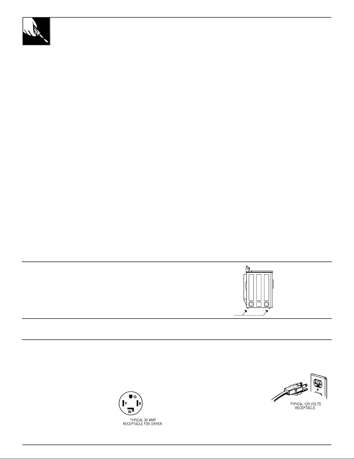
ELECTRICAL POWER SUPPLY
CAUTION: NEVER USE AN EXTENSION CORD WITH THIS APPLIANCE.
Note: If the electrical power supply provided does not meet the specifications listed below, call a licensed electrician.
FOR ELECTRIC DRYERS, POWER SUPPLY...
1. Must be of 120/240 volts or 120/208 volts, 60 Hz
circuit with wall receptacle as
shown beside.
2. Must be protected with 30A
FUSES OR BREAKERS.
3. Must be WELL GROUNDED.
4. Must CONFORM TO LOCAL
CODES.
8
FOR GAS DRYERS, POWER SUPPLY...
1. Must be of 120 volts, 60 Hz
circuit with wall receptacle as
shown beside.
2. Must be protected with 15 or
20A FUSES OR BREAKER.
3. Must be WELL GROUNDED.
4. Installation must be in accordance
with the current CSA C22.1 Canadian Electrical code
part 1 and/or local codes.
INSTALLATION – GAS DRYER
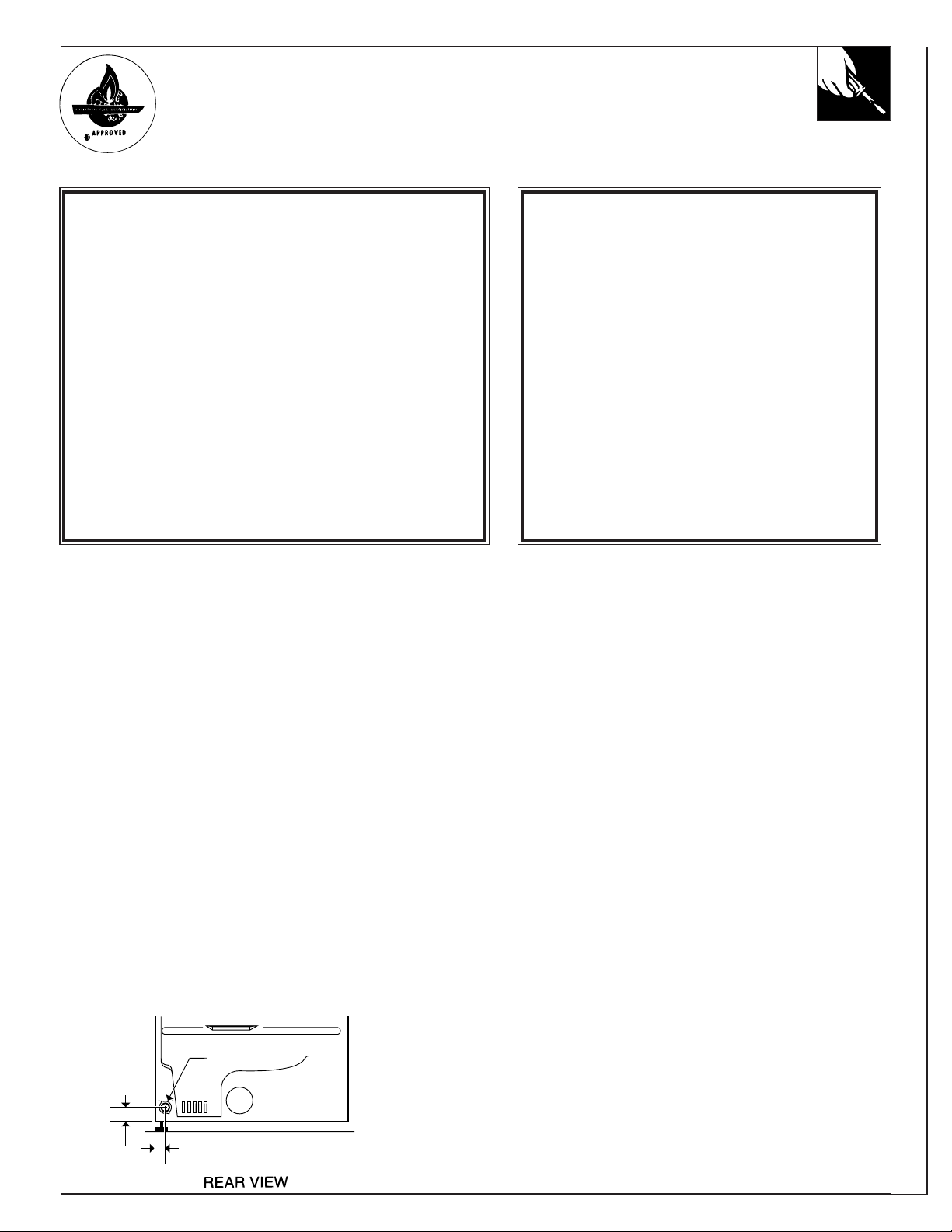
51mm
(2")
66 mm
(2 5/8")
MALE THREAD GAS SUPPLY
9.52 mm (3/8")
IMPORTANT - OBSERVE ALL GOVERNING CODES
Dryer must be levelled and rest firmly on the floor.
Dryer must be exhausted to the outdoors.
FOR YOUR SAFETY
What to do if you smell gas
• Do not try to light appliance.
• Do not touch any electrical switch ; do not use
any phone in your building.
• Clear the room, building or area of all occupants.
• Immediately call your gas supplier from a
neighbor’s phone. Follow the gas supplier’s
instructions.
• If you can not reach your gas supplier, call fire
department.
• Installation and service must be performed by
a qualified installer, service agency, or the gas
supplier.
FOR YOUR SAFETY
Do not store or use gasoline or
other flammable vapors and
liquids in the vicinity of this or
any other appliance.
Installation Instructions
GAS CONNECTION INFORMATION
Installation must conform with local Gas Codes and
with CAN/CGA-B149, Natural Gas Installation Code.
Some local codes restrict installation of gas appliances
in garages. They must be 45 cm (18”) off the ground
and protected by a barrier from vehicules.
GAS BURNER ORIFICE
This gas dryer is equipped with a Valve & Burner
Assembly for use ONLY WITH ONE TYPE OF GAS.
Using the appropriate kit, your local service
organization can convert this dryer for use with the
alternate fuel.
Use kit WE25M35 to convert from Natural Gas to LP
Gases (Propane).
Use kit WE25M36 to convert from LP Gases to Natural
Gas.
WARNING: CONVERSION SHALL BE CARRIED
OUT IN ACCORDANCE WITH THE
REQUIREMENTS OF THE PROVINCIAL
AUTHORITIES HAVING JURISDICTION AND/OR
ACCORDANCE WITH THE REQUIREMENTS OF
THE CAN/CGA B149.1 AND B149.2
INSTALLATION CODE.
GAS SUPPLY
• Supply line is to be 12.7 mm (1/2 in) rigid pipe.
(9.53 mm (3/8 in) copper tubing may be used if the
dryer is operated on propane gas) and equipped with
an accessible shutoff within 6 feet (2 m) from, and in
the same room with the dryer. Increase pipe size for
runs longer than 20 feet (7 m).
• During pressure test:
– When test pressure is in excess of 1/2 PSIG
(3.45kPa), disconnect dryer and its individual
shutoff valve from gas supply line prior to test.
– When test pressure is equal to or less than 1/2 PSIG
(3.45kPa), close the dryer shutoff valve prior to test.
• A 3.18 mm (1/8 in) National Pipe Taper thread
plugged tapping, accessible for test gauge connection,
must be installed immediately upstream of the gas
supply connection to the dryer. Contact your local gas
utility should you have questions on the installation of
the plugged tapping.
• Pipe dope must be resistant to the action of propane
and applied sparingly to all male threads.
• If local codes permit, it is recommended the dryer be
connected to the gas supply with approved semi-rigid
metal tubing or listed connectors.
LEAK TEST
Check all connections for leaks with soapy solution or
equivalent. Leak test solutions must not contain ammonia
which could cause damage to brass fittings or pipe.
CAUTION: NEVER USE AN OPEN FLAME TO
TEST FOR GAS LEAKS.
9
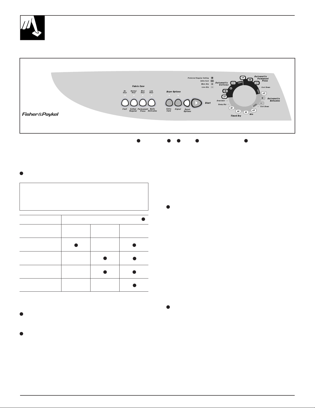
OPERATING YOUR DRYER
WARNING – To reduce the risk of fire, electric shock, or injury to persons
when using your appliance read the IMPORTANT SAFETY INSTRUCTIONS
before operating this appliance.
Features and appearances may vary
1
Drying Selections. Select the proper heat on the Fabric
Care selector for your load.
NOTE: Drying times will vary according to the type of
heat used (Electric, Natural gas or LP gas), size of load,
types of fabrics, wetness of clothes, and condition of
exhaust ducts.
Should be used with cycles indicated
Drying Automatic Automatic
Selections Cottons Perm. Press Timed
Cottons
High Heat
Perm. Press
Medium Heat
Knits/Delicates
Low Heat
Fluff
No Heat*
*Fluff-No Heat option can be used with an automatic cycle, but for best
performance it is recommended to be used with a timed cycle.
2
Cycle Selector. Turn the Cycle Selector to the desired
cycle setting. The selector may be turned in either
direction.
3
Press Guard Cycle. (Available on some models.)
The Press Guard cycle operates only with the
Automatic Permanent Press and Automatic Cottons
cycles. Turn the Press Guard knob to SET or press the
pad to select, and turn the Cycle Selector Dial to the
desired amount of heated drying time.
51 3 4 2
To minimize the wrinkle setting in clothes, the Press
Guard cycle provides from15 to 20 minutes of no-heat
tumbling after the clothes are dry.
Used the End Cycle Signal to remind you to remove
the dried laundry.
4
End Cycle Signal. (Available on some models.)
Set End Cycle Signal, if desired. This signal operates
with any cycle on some models. The control can be set
anywhere between OFF and LOUD, depending on the
desired sound level. The signal will start to sound just
before the end of the cycle to remind you to remove the
clothes. To stop the signal while sounding, turn the
signal control to OFF or advance the Cycle Selector to
OFF.
This signal should always be used when drying
polyester knits or permanent press items which should
be removed as soon as the dryer stops to help prevent
setting of wrinkles.
If the signal is on and you choose the Press Guard
cycle, you will hear the signal sound on and off
throughout the cycle. This reminds you that the clothes
are dry.
5
Start. Turn the Start knob or press the Push to Start
button to start the dryer. (Opening the door during
operation stops the dryer. To restart, close the door and
follow above directions.)
10

OPERATING YOUR DRYER
Polyester Knits & Permanent Press Drying Tips
•DO NOT OVERLOAD-
Garments being dried or
dewrinkled should tumble
freely.
•REMOVE CLOTHES
PROMPTLY-
To help prevent wrinkling,
remove clothes from the dryer
promptly at the end of the
drying cycles.
•PLACE ON HANGERS-
Permanent press and polyester
knit garments look best if
placed on hangers after drying.
HOW TO LOAD THE CLOTHES
Don’t overload your dryer. Crowded
loads don’t dry efficiently and clothes
may be unnecessarily wrinkled. Loads
should look like this:
HOW TO SORT CLOTHES
As a general rule, sort clothes by surface texture, fabric, colour and weight, as you would for your washer.
Operating Instructions/Care and Cleaning
Dryer Exterior
Wipe off any spills or washing
compounds. Wipe or dust with a
damp cloth. Try not to strike the
surface with sharp objects.
Lint filter
Before every
dryer use, clean the
lint filter. Put your
moistened fingers at
one side of the filter
and wipe in a sideways
motion all the way
across to the other side.
CARE AND CLEANING
Dryer control panel and finishes
may be damaged by some laundry
pre-treatment soil and stain
remover products if such products
are sprayed on or have direct
contact with the dryer.
CARE AND CLEANING
To keep your dryer
operating at peak
performance.
periodically, remove
the lint filter and
insert the suction hose
from your vacuum
cleaner into the
opening.
Apply these pre-treatment products
away from the dryer. The fabric
may then be washed and dried
normally. Damage to your dryer
caused by pre-treatment products is
not covered by your warranty.
11

SUGGESTED FABRIC
AND DRYING SELECTIONS
Cycle Suggested For Clothes Load/Fabrics such as: Drying Selection
Automatic Cottons
Automatic Permanent Press
• Cottons and linens
• Permanent press fabrics with cotton
High
Medium
• Down-filled garments, if machine washing and
drying is recommended
• Synthetics
Automatic Permanent Press
with Extra Care (Automatic
Delicates if available)
Timed
• Silks and wools
• Rayon and acetate
• Pillows*
Low
Medium or Low
• Blankets**
Cotton
Synthetics or Down
• Extra large items***
Cottons/Reg Heat
Medium or Low
Medium Heat
The terms High, Medium and Low Heat are those usually found on fabric care labels.
For best results, follow your fabric care labels.
MAY BE
DRIED IN A
TUMBLE
DRYER AT
MEDIUM TO
REGULAR
(green) (yellow) (green) (green) (yellow)
SETTING.
MAY BE
DRIED IN A
TUMBLE
DRYER AT
LOW
SETTING.
SHOULD BE
HUNG TO
DRY.
SHOULD BE
HUNG
SOAKING
WET TO
DRIP DRY.
SHOULD BE
DRIED ON A
FLAT
SURFACE.
*Pillows
**Blankets
***Extra Large Items-
Queen or King size
sheets; Blankets or
Spreads; Mattress
Covers/Pads;
Snowsuits.
12
Check ticking for holes or weak seams where feathers or filling could escape. DRY ONLY ONE
PILLOW AT A TIME. Set dryer for maximum time. Stop dryer occasionally and shake pillow to
redistribute filling for more even drying. Check pillow at end of drying time – if not completely dry,
return pillow to dryer and reset for more drying time. Feather pillows dry very slowly and must be
dried completely to prevent mildew. DO NOT tumble dry pillows containing kapok.
Add 2 or 4 dry towels to the blanket in the dryer. Set timer for 20-25 minutes. DO NOT set control
for more than 25 minutes. DRY ONLY ONE BLANKET AT A TIME. Remove blanket at the end of
the cycle and block the blanket back to its original shape. Allow to dry thoroughly before storing.
First setting – 20 minutes; check and redistribute load. Then set timer for 15 minutes; check load
again. Reset timer at 5 minute intervals, checking after each 5 minutes to make sure that the articles
do not fill the dryer drum; many large items, when wet, have ample room in the dryer, but as they
dry and fluff up, they may not have room to tumble. CAUTION: If large items do not have room to
tumble, the air flow may be blocked, which could result in scorching your valuable items. NOTE:
Mattress cover/pads should be dried alone.

HOW TO OPERATE YOUR DRYER
The Difference Between Automatic and Timed Drying
Automatic Drying (Electronic)
(on some models)
When using the Automatic Cycles,
the Electronic Sensor Control
system continually senses the
moisture in the tumbling clothes,
determines when they are dried to
your pre-selected setting, and
terminates the cycle automatically.
The Cycle Selector will not
advance until clothes have reached
a certain degree of dryness.
Automatic Drying
When using the Automatic Cycles,
the Automatic Dry Control system
continually senses the temperature
of the air in the dryer drum. Wet
laundry keeps this air cool. When
laundry is dry enough (and the
drum air warms enough) the heat
turns off. When the air cools, the
heat turns back on. This off and on
cycling may happen a number of
times (depending on the fabric,
load size and Cycle Selector
setting). The Cycle Selector
advances (when the heat is off)
until it automatically turns off the
dryer.
Drying Selections Guide for the Automatic Cycles
DRY / SEC
Auto
Cottons
Cotons
DRY / SEC
DRY / SEC
Auto Per
& Knits
DRY / SEC
COOL DOW
REFROIDIS
Auto
Cottons
Cotons
DRY / SEC
DRY / SEC
DRY / SEC
Auto Per
& Knits
DRY / SEC
COOL DOW
REFROIDIS
Timed Drying
When using the Timed Cycles, you
select the number of minutes you
wish the dryer to run and it turns
off at the end of this time period.
DRY / SEC
Auto
Cottons
Cotons
DRY / SEC
DRY / SEC
Auto Per
& Knits
DRY / SEC
COOL DOW
REFROIDIS
How to Operate Your Dryer/Drying Selections/Accessories
As a general guideline...
Set near the midway position
• For most normal loads.
Accessories
•DRYING RACK (available on
some models)
A handy door rack is provided for
drying solid articles such as
stuffed toys and washable running
shoes without tumbling. This rack
is easy to install, just hook on the
bottom of the front opening.
The drying rack must be used
with a timed cycle.
Note:When rack is used
make sure there are
no loose articles in
the drum.
Set toward Less Dry
•For light-weight fabric loads
•If you desire to remove less
moisture
•For very small loads
• DRUM LAMP
(available on some
models)
BEFORE
REPLACING LIGHT
BULB, BE SURE TO
UNPLUG THE
DRYER POWER
CORD. Simply reach
above loading
opening from inside
drum. Remove bulb
and replace with the
same type and rating
bulb.
Set toward More Dry
•For loads that include heavyweight fabrics.
• If you desire to remove more
moisture.
13

MAXIMIZE YOUR DRYER EFFICIENCY
BY KEEPING THE EXHAUST DUCT CLEAN.
1. Disconnect the plug from the wall socket
or turn off the circuit breaker to cut the
electrical supply to the dryer.
2. Disconnect duct from dryer.
3. Clean exhaust duct from end where dryer is
connected to the exhaust hood using:
• the hose attachment of your vacuum cleaner:
• a dust rag attached to a pole (for straight stretches)
or to a drain cleaning wire (for less accessible
turns).
4. Inspect exhaust hood. To minimize resistance to the
exhaust air flow:
• flap must move freely (you may check with a
mirror);
• flap should be fully open when dryer is on;
• ensure that no wildlife (birds, insects,...) have
nested inside the duct.
CLEANING LINT FROM YOUR DRYER
Combustible lint may collect on the inside of the dryer cabinet. CLEAN EVERY 2 TO 3 YEARS OR
MORE OFTEN DEPENDING ON USAGE. Cleaning should be done by a qualified service person.
ALWAYS VERIFY PROPER OPERATION AFTER SERVICING
14

QUESTIONS?
USE THIS PROBLEM SOLVER
PROBLEM POSSIBLE CAUSE
DRYER WON’T START • Dryer unplugged. Make sure power cord is plugged in.
• No power to dryer. Check fuses and circuit breakers to make sure dryer is getting
current. Most electric dryers use two.
• Controls improperly set. Make sure controls are set and that the Start button is
pressed or turned. Opening the door during operation stops the dryer. To restart,
close the door and push the Start button.
CLOTHES TAKE TOO • Controls improperly set. Check all controls to make sure they are correctly set for
LONG TO DRY the load you want to dry. See the How to Operate Your Dryer section.
• Clogged lint filter. Clean filter before every load. Periodically remove lint filter
and clean area under it with vacuum cleaner. See the Care and Cleaning section.
• Improper ducting. Make sure dryer is ducted in accordance with the Installation
Instructions.
• Obstruction in exhaust ducting. Make sure ducting is clean and free of
obstruction; make sure damper in outside wall cap operates easily. If flexible
ducting is used, be sure it is not kinked and is properly installed according to the
Installation Instructions.
• Blown fuses or tripped circuit breakers. Check household fuses or circuit
breakers. Most electric dryers use two. It is possible for one to be blown or
tripped and the dryer still tumble without heat.
• Improper sorting. Do not mix heavy, hard-to-dry items with lightweight articles.
• Too many items in dryer. Dry only one washer load at a time. Do not combine
loads.
• Too few items in dryer. If drying only one article, add two more similar articles,
even if dry, to ensure proper tumbling.
SHRINKAGE • Some fabrics will shrink whether machine washed and tumble dried or washed
by hand and drip dried; others may be safely washed but will shrink in a dryer.
Follow Garment Manufacturers’Care Labels exactly. If in doubt, do not machine
wash or tumble dry.
WRINKLING • Leaving clothes in dryer after tumbling stops. Remove clothes promptly and
hang them immediately.
• Improper loads. Avoid laundering heavy Permanent Press items, such as work
clothes, with lighter Permanent Press items, such as shirts or blouses. Do not
wash or dry Permanent Press with regular laundry.
• Failure to use fabric softener. Proper use of fabric softener will minimize
wrinkling.
TO REMOVE WRINKLES Try one or more of these suggestions
• Retumble on Perma Press setting.
• Rerinse and dry on Perma Press setting.
• If unsuccessful, retumble on high heat for 10 - 12 minutes and hang immediately
• Iron carefully
• Send to dry cleaners for pressing
• Some wrinkles may remain which cannot be removed.*
* NOTE: If you follow good laundry procedures and Permanent Press clothes still
come out wrinkled, the finish may not be good quality. Also, in permanent press
synthetic/cotton blends, the cotton portion of the fabric can eventually wear
away leaving only the synthetic. Since it’s the cotton portion which is treated for
Permanent Press, a loss or decrease of Permanent Press performance will result.
“Easy Care” fabrics may eventually lose their finish and wrinkle even with
proper care.
Questions? Use This Problem Solver
IF DRYER STILL DOES NOT OPERATE, call for Service, GIVE THE MODEL AND SERIAL NUMBERS AND
DESCRIBE THE SYMPTOMS OF THE DRYER.
15

YOUR AUTOMATIC CLOTHES DRYER
WARRANTY
Save proof of original purchase date such as your sales slip or copy of the check
cashed to establish warranty period.
WHAT IS COVERED BY THE WARRANTY
FULL TWO-YEAR WARRANTY
For two years from the date of original purchase, we will provide, free of charge, parts
and service labor in your home to repair or replace any part of the dryer that fails
because of a manufacturing defect.
This warranty is extended to the original purchaser and any succeeding owner for
products purchased for ordinary home use in Canada.
All warranty will be provided by a Fisher & Paykel Authorized Service Agent during
normal working hours. Should your appliance need service, during the warranty period or
beyond:
in Canada call DIRECT 1 877 744 7400
WHAT IS NOT COVERED BY THE WARRANTY
- Service trips to your home to teach you how to use the product.
Read your USE & CARE book. If you then have any questions about operating the
product, please contact your dealer or
in Canada call DIRECT 1 877 744 7400
- Improper installation.
If you have an installation problem, contact your dealer or installer. You care
responsible for providing adequate electrical, exhausting and other connection
facilities.
- Replacement of house fuses or resetting of circuit breaker.
- Failure of the product if it is misused, or used for other than the intended purpose or
used commercially.
- Damage to product caused by accident, fire, floods or Acts of God.
- Correction of unauthorized repairs.
- Normal recommended maintenance as set out in the products USE & CARE book.
WARRANTOR IS NOT RESPONSIBLE FOR CONSEQUENTIAL DAMAGES
Some states do not allow the exclusion or limitation of incidental or consequential
damages, so the above limitations or exclusion may not apply to you. This warranty
gives you specific legal rights, and you may also have other rights which vary from
state to state. To know what your legal rights are in your state, consult your local or
state consumer affairs office or your state’s Attorney General.
Warrantor: Fisher & Paykel Appliances Inc.
If further help is needed concerning this warranty write:
Fisher & Paykel Appliance Inc., 27 Hubble, Irvine California, CA 92618-9858
16

SÉCHEUSE
Guide d’utilisation
et d’entretien
et directives d’installation
PAPIER RECYCLÉ
RECYCLABLE
Notre environnement nous tient à coeur.
500A277P046

Mesures de sécurité................ 3, 4
Directives d’installation
Directives d’inversion de la porte...............5
Évacuation...................................................6, 7
Sécheuse électrique ......................................8
Sécheuse à gaz ..........................................8, 9
Entretien et nettoyage
Évacuation de la sécheuse ........................14
Extérieur.........................................................11
Filtre à charpie ..............................................11
Remplacement de l’ampoule ...................13
Guide de dépannage............... 15
Fonctionnement et conseils
Avertisseur ....................................................10
Chargement...........................................11, 15
Conseils pour le séchage
• Des apprêts permanents................11, 15
• Des tricots ..........................................11, 12
Directives spéciales.....................................12
Filtre à charpie ..............................................11
Fonctionnement ....................10, 11, 12, 13
Guide de séchage automatique .......12, 13
Programme Soins + .............................10, 12
Programmes suggérés...............................12
Réglage des programmes..................10, 12
Séchage automatique ................................13
Séchage électronique par capteur..........13
Séchage minuté....................................12, 13
Tri des vêtements ........................................12
Lisez attentivement le
présent guide
Il a été conçu pour vous aider à faire
fonctionner et entretenir
convenablement votre nouvelle
sécheuse.
Gardez-le à la portée de la main pour y
trouver les réponses à vos questions.
Si vous desirez de plus amples
renseignements ou avez besoin d’aide,
écrivez (en indiquant votre numéro de
téléphone) à l’adresse suivante :
Directeur, Relations avec les
consommateurs
Camco Inc.
1, Factory Lane, bureau 310
Moncton (Nouveau-Brunswick)
E1C 9M3
Services à la clientèle
Garantie..........................................................16
Numéros de modèle et de série .................2
Réparations......................................................2
Économisez du temps et
de l’argent
Avant d’appeler un réparateur,
consultez le Guide de dépannage. Vous
y trouverez les causes de problèmes de
fonctionnement mineurs que vous
pouvez corriger vous-même.
Si la sécheuse que vous
avez reçue est
endommagée...
Communiquez immédiatement avec le
marchand (ou l’entrepreneur) qui vous
a vendu l’appareil.
Transcrivez les numéros
de modèle et de série
Ils sont inscrits sur une plaque située à
l’avant de la sécheuse, derrière la porte.
Ces numéros figurent également sur la
carte d’enregistrement qui accompagne
votre sécheuse. Avant de nous
retourner cette carte, veuillez inscrire
ces numéros ci-dessous :
Numéro de modèle
Numéro de série
Mentionnez ces numéros dans toute
correspondance ou appel de service
concernant votre sécheuse.
MISE EN GARDE : Pour votre sécurité, veuillez suivre à la lettre les directives données dans le présent
manuel afin de réduire au minimum les risques d’incendie ou d’explosion, ou de prévenir tout dommage,
blessure ou décès.
– Ne rangez pas ou n’utilisez pas d’essence ou
autres liquides ou vapeurs inflammables à
proximité de votre sécheuse ou de tout autre
électroménager.
– SI VOUS REMARQUEZ UNE ODEUR
DE GAZ
• Ne faites fonctionner aucun appareil électrique.
• N’actionnez aucun interrupteur électrique;
n’utilisez aucun téléphone dans votre édifice.
• Communiquez immédiatement avec votre
fournisseur de gaz en utilisant le téléphone d’un
voisin. Suivez les directives qu’il vous donnera.
• Si vous ne pouvez rejoindre votre fournisseur de
gaz, appelez les pompiers.
– L’installation et les réparations doivent être
effectuées par un installateur qualifié, une
entreprise de réparation ou le fournisseur de gaz.
• Faites sortir tous les occupants de la pièce ou
de l’édifice, ou faites évacuer les environs.
2

MESURES DE SÉCURITÉ IMPORTANTES
Veuillez lire toutes les directives avant d’utiliser l’appareil.
Mise en garde - Il est extrêmement important de lire et de suivre les
directives ci-dessous, afin d’éviter les blessures ou les dommages
matériels que pourrait causer un incendie.
• N’utilisez cet appareil que pour l’usage auquel il est
destiné, comme expliqué dans le présent Guide
d’utilisation et d’entretien.
Avant d’utiliser votre sécheuse, assurez-vous
qu’elle a été adéquatement installée,
conformément aux Directives d’installation.
– L’appareil doit être adéquatement mis à la terre,
conformément à tous les codes locaux. Pour plus de
détails, consultez les Directives d’installation.
– Pour un fonctionnement satisfaisant du système de
commande de la sécheuse, installez l’appareil dans
un endroit où la température est supérieure à 50 ˚F
(10 ˚C). Installez ou entreposez la sécheuse dans un
endroit où elle ne sera pas exposée aux intempéries.
– Branchez l’appareil à un circuit protégé de capacité
appropriée afin d’éviter toute surcharge électrique.
– Il est FORTEMENT RECOMMANDÉ d’évacuer
l’air de la sécheuse vers l’extérieur afin de prévenir
l’accumulation d’une quantité importante d’humidité et
de charpie dans la pièce. Veuillez suivre à la lettre les
mesures d’évacuation indiquées dans les Directives
d’installation.
Ne réparez ou ne remplacez aucune pièce
de cet appareil, ou ne tentez pas de le faire,
à moins que cela ne soit spécifiquement
recommandé dans le présent Guide
d’utilisation et d’entretien ou indiqué dans les
directives de réparation que vous comprenez et que
vous êtes en mesure de suivre.
Lorsque vous débranchez l’appareil, tirez
sur la fiche et non pas sur le cordon, afin
d’éviter d’endommager le cordon ou le
raccord entre le cordon et la fiche. Installez
le cordon de sorte que personne ne trébuche
dessus ou qu’il ne soit pas exposé à des dommages ou
soumis à des contraintes.
Pour réduire les risques d’incendie
• Conduit d’évacuation – Voir les Directives
d’installation. N’utilisez qu’un conduit métallique
rigide ou souple de 4 po de diamètre pour
l’évacuation de l’air vers l’extérieur.
L’UTILISATION D’UN CONDUIT DE PLASTIQUE
OU FABRIQUÉ AVEC TOUT AUTRE MATÉRIAU
COMBUSTIBLE PEUT CAUSER UN INCENDIE.
LORSQU’UN CONDUIT EN MÉTAL SOUPLE OU
AUTRE S’AFFAISSE OU DEVIENT OBSTRUÉ AU
COURS DE L’UTILISATION OU DE
L’INSTALLATION, IL PEUT ÉGALEMENT CAUSER
UN INCENDIE.
• Ne faites pas sécher à la chaleur des articles
contenant du caoutchouc, du plastique ou autres
matériaux similaires (comme des soutiens-gorge
préformés, des chaussures de tennis, des caoutchoucs,
des tapis de bain, des carpettes, des bavoirs, des oreillers,
des culottes de bébé, des sacs de plastique, etc.) car ces
matériaux peuvent fondre ou brûler. De plus, dans
certaines circonstances, certains matériaux de
caoutchouc peuvent causer un incendie par combustion
spontanée lorsqu’ils sont chauffés.
• Ne rangez pas des articles qui peuvent fondre ou brûler
(comme des vêtements, du papier, des articles ou des
contenants de plastique, etc.) sur le dessus de la sécheuse
pendant qu’elle fonctionne.
• Les vêtements portant la mention «Faire sécher loin
de la chaleur» (comme les gilets de sauvetage
contenant du kapok) ne doivent pas être séchés dans
votre sécheuse.
• Ne lavez pas ou ne faites pas sécher des
articles qui ont été lavés avec les produits
combustibles ou explosifs, ou qui ont été
trempés dans ces produits ou qui en sont
tachés (comme de la cire, de la peinture,
de l’essence, des dégraissants, des solvants pour le
nettoyage à sec, du kérosène, etc.) car ils risquent de
s’enflammer ou d’exploser. Ne versez pas ces
substances dans l’eau de la laveuse. N’utilisez pas ces
substances à proximité de votre laveuse ou de votre
sécheuse pendant qu’elles fonctionnent.
• Ne placez pas dans la sécheuse ou n’utilisez pas à
proximité de celle-ci tout article ayant été utilisé avec un
solvant dégraissant ou imbibé d’une substance
inflammable (comme des chiffons de nettoyage, des
vadrouilles, des serviettes utilisées dans les salons de
beauté, les restaurants ou les salons de coiffure, etc.), à
moins qu’il ait été débarrassé de toute trace et toute
vapeur de substance inflammable. On utilise à la maison
de nombreux produits inflammables comme l’acétone,
l’alcool dénaturé, l’essence, le kérosène, certains
produits nettoyants ménagers, certains détachants, la
térébenthine, la cire, les décapants pour la cire et les
produits contenant du distillat de pétrole.
(suite à la page suivante)
Mesures de sécurité importantes
3

MESURES DE SÉCURITÉ IMPORTANTES
• Avant chaque séchage, nettoyez le
filtre à charpie afin de prévenir
l’accumulation de charpie à l’intérieur
de la sécheuse ou dans la pièce.
NE FAITES PAS FONCTIONNER LA
SÉCHEUSE SANS LE FILTRE À
CHARPIE.
• Ne laissez pas s’accumuler autour et au-dessous de
vos électroménagers des matériaux combustibles,
comme de la charpie, du papier, des chiffons, des
produits chimiques, etc.
• Inspectez régulièrement le conduit d’évacuation pour
vous assurer qu’il n’a pas été écrasé ou qu’il n’est pas
obstrué de quelque façon que ce soit.
• L’intérieur de l’appareil et le raccord du conduit
d’évacuation à l’intérieur de la sécheuse doivent être
nettoyés tous les 2 ou 3 ans, ou plus souvent si
nécessaire, par un réparateur qualifié. Voir la section
«Entretien et nettoyage».
Pour réduire les risques de blessures
• Ne vous penchez jamais dans la sécheuse pendant que
le tambour tourne. Avant de charger ou de décharger la
sécheuse ou d’y ajouter des vêtements, attendez que le
tambour se soit complètement arrêté.
• Ne faites pas sécher d’articles en fibre de verre dans
votre sécheuse. Des particules pourraient demeurer dans
la sécheuse et être recueillies par les vêtements lors d’un
séchage subséquent, ce qui risque de causer des irritations
cutanées.
• La lessive peut atténuer les propriétés
ignifugeantes des tissus. Pour éviter cette
situation, suivez à la lettre les directives
données par le fabricant du vêtement.
• Il faut exercer une étroite surveillance
lorsque vous faites fonctionner cet
appareil en présence d’enfants. Ne les
laissez pas jouer avec l’appareil ni
monter dessus, ou s’introduire à
l’intérieur d’un vieil appareil qui ne sert
plus. Jetez de la façon appropriée les vieux
électroménagers ainsi que le matériel d’emballage.
Avant de jeter ou d’entreposer une sécheuse, enlevez
toujours la porte.
CONSERVEZ
CES DIRECTIVES
• Gardez tous les produits de lessive
(comme les détersifs, les javellisants, les
assouplissants, etc.) hors de la portée
des enfants, de préférence dans une
armoire verrouillée. Observez toutes les
mises en garde sur les emballages afin
d’éviter les accidents.
• Gardez le sol propre et sec à proximité de vos
électroménagers pour ne pas glisser.
• Pour réduire les risques de chocs
électriques, débranchez toujours
l’appareil avant de le réparer ou de le
nettoyer (sauf pour enlever et nettoyer le filtre
à charpie).
• REMARQUE : Le fait de placer le
sélecteur de programme à OFF ne coupe
PAS l’alimentation électrique de l’appareil.
• Ne trafiquez pas les commandes de l’appareil.
• Ne faites pas fonctionner l’appareil s’il est
endommagé, défectueux, partiellement démonté, ou si
des pièces sont manquantes ou défectueuses, ou si le
cordon d’alimentation ou la fiche sont endommagés.
• Ne montez jamais sur le dessus de la sécheuse.
• Ne placez PAS dans votre sécheuse des articles
imbibés d’huile de cuisson. Les articles contaminés par
de l’huile de cuisson peuvent provoquer une réaction
chimique et les vêtements pourraient prendre feu.
• Si votre sécheuse fonctionne à gaz, elle est pourvue
d’un système d’allumage électrique automatique et ne
possède pas de veilleuse. N’ESSAYEZ PAS DE
L’ALLUMER AVEC UNE ALLUMETTE. Vous risquez
de vous brûler si vous approchez votre main du brûleur et
que le dispositif d’allumage automatique s’allume.
Assouplissants textiles pour la sécheuse ou
produits antistatiques
Il est possible que vous désiriez assouplir votre lessive ou
réduire le collement électrostatique. Nous vous
recommandons d’utiliser un assouplissant liquide au cours
du programme de lavage, conformément aux directives du
fabricant de ce type de produit, ou de faire l’essai d’un
assouplissant textile pour la sécheuse, pour lequel le
fabricant certifie sur l’emballage que son produit peut être
utilisé en toute sécurité dans la sécheuse.
La responsabilité des problèmes de rendement ou de
fonctionnement, qui ne sont pas couverts par la garantie de
cet appareil et qui sont attribuables à l’utilisation de ces
produits, relève du fabricant de ces produits.
4

DIRECTIVES D’INVERSION DE LA PORTE
Les directives qui suivent permettent de transférer du côté
gauche les charnières situées du côté droit.
Outils nécessaires
Tournevis Phillips standard n˚ 2
PORTE DE LA SÉCHEUSE
1. Ouvrez la porte et enlevez les capuchons situés du côté
opposé des charnières.
(Pour enlever les capuchons,
utilisez un couteau à mastic
dont l’extrémité de la lame est
recouverte de ruban gommé ou
des pinces à becs pointus. Faites
attention de ne pas égratigner
la peinture.)
2. Ouvrez complètement la porte,
puis enlevez la vis inférieure qui
fixe chacune des charnières au
panneau avant de la sécheuse.
(N’enlevez pas les vis qui se
trouvent sur la porte.)
Si vous désirez retransférer les charnières du côté droit,
suivez les mêmes directives (en remplaçant simplement le
mot «gauche» par le mot «droit» et vice versa).
6. Faites pivoter la porte sur
elle-même à 180˚.
Installez-la du côté opposé
du panneau avant en
l’ABAISSANT jusqu’à ce
que la charnière supérieure
et la charnière inférieure
reposent sur les vis
supérieures installées à
e
étape.
la 3
7. À l’aide des autres vis,
fixez la partie inférieure de
chacune des charnières.
8. Serrez les vis supérieures
de chacune des charnières.
Directives d’inversion de la porte
3. Revissez ces vis à moitié dans les trous supérieurs
de chaque charnière, du côté opposé de la porte
(aux endroits où vous avez enlevé les capuchons).
4. Dévissez à moitié la dernière vis
de chacune des charnières sur le
panneau avant de la sécheuse.
5. D’une main, saisissez le dessus de
la porte et de l’autre, tenez la partie
inférieure de la porte. Dégagez
ensuite la porte du panneau avant
de la sécheuse en la SOULEVANT
et la TIRANT vers vous.
9. Réinstallez les capuchons de plastique du côté où se
trouvaient les vis de charnière que vous avez
enlevées.
5

298mm
(11 3/4")
91mm
(3 1/2")
NOTE : AJOUTER AUX
91mm (3 1/2")
LA DISTANCE
ENTRE LE FOND DU
CABINET ET LA SURFACE
DU PLANCHER
DIRECTIVES D’INSTALLATION
ÉVACUATION
L’installation et les réparations doivent être confiées à un installateur qualifié, à une entreprise de réparation ou
au fournisseur de gaz.
IMPORTANT : Faites installer correctement votre sécheuse.
REMARQUE : Les MISES EN GARDE et les directives IMPORTANTES données dans le présent manuel ne couvrent
pas toutes les conditions et situations possibles qui peuvent survenir. Il est bien évident que les personnes qui installent,
entretiennent ou font fonctionner la sécheuse DOIVENT faire preuve de jugement, d’attention et de prudence.
Si cet électroménager n’est pas installé, entretenu ou utilisé conformément aux directives du fabricant, il peut se produire
des conditions pouvant occasionner des blessures ou des dommages matériels.
Cette sécheuse a été préparée en vue d’une évacuation par
l’arrière (voir la fig. 1).
MISES EN GARDE
• N’UTILISEZ PAS UN CONDUIT FLEXIBLE NON
MÉTALLIQUE.
• N’utilisez jamais un conduit flexible à l’intérieur de la
sécheuse.
• Ne faites pas évacuer l’air de la sécheuse dans une
cheminée, une hotte de cuisinière, un évent à gaz, un
plancher ou un grenier. Le mélange de charpie et
d’humidité pourrait constituer un risque d’incendie ou
causer des dommages.
• Prévoyez un accès pour l’inspection et le nettoyage du
système d’évacuation au moins une fois par année. (Voir
la section « Entretien et nettoyage ».)
LONGUEUR DU CONDUIT D’ÉVACUATION
La longueur MAXIMALE PERMISE du système
d’évacuation dépend du type de conduit, du nombre de
coudes, du type d’évent mural, ainsi que des conditions
indiquées ci-dessous.
La longueur maximale permise des conduits rigides et des
conduits métalliques flexibles est indiquée dans le tableau
à la page suivante. Il est déconseillé d’installer plus de
quatre coudes de 90˚.
VÉRIFICATION DU SYSTÈME D’ÉVACUATIONÉVENT MURAL
• Installez l’évent de façon à empêcher le retour d’air ou
l’entrée d’oiseaux ou d’autres animaux.
• L’évent doit offrir le moins de résistance possible à
l’évacuation de l’air et n’exiger que peu ou pas
d’entretien.
• L’évent doit être installé à au moins 300 mm (12 po) audessus du sol ou de tout obstacle, et son ouverture doit
être dirigée vers le bas.
• Si vous utilisez un évent de toiture ou à persiennes,
celui-ci doit avoir des caractéristiques équivalentes à
celles d’un évent mural de 100 mm (4 po) en ce qui
concerne la résistance à l’évacuation de l’air, le retour
d’air et l’entretien.
LONGUEUR DE CONDUIT ENTRE LES COUDES
Prévoyez entre chacun des coudes une longueur de
conduit droit d’au moins 1 m (3 pi), y compris entre le
dernier coude et l’évent mural. Chaque fois que deux
coudes sont espacés d’une longueur inférieure à 1 m
(3 pi), réduisez de 3 m (10 pi) la longueur maximale de
conduit indiquée dans le tableau.
6
AUTRES TYPES DE COUDES
• Un coude de 45˚ ou moins : ne pas tenir compte
• Deux coudes de 45˚ ou moins : suivre les indications
données pour un coude de 90˚.
• Chaque coude de plus de 45˚ : suivre les indications
données pour un coude de 90˚.
SCELLEMENT DES JOINTS
• Tous les joints doivent être étanches pour éviter les
fuites d’air. L’extrémité mâle de chaque section de
conduit doit être orientée en sens contraire par rapport à
la sécheuse.
• N’assemblez pas les sections de conduit avec des vis qui
dépassent à l’intérieur du conduit. Celles-ci risquent de
créer des points d’accumulation de charpie.
• Assurez l’étanchéité à l’air et à l’humidité des conduits
en recouvrant les joints de ruban gommé pour conduit.
ISOLATION
• Les conduits qui traversent une zone non chauffée ou
qui se trouvent à proximité d’un conduit de
climatisation doivent être isolés afin de réduire la
condensation et l’accumulation de charpie, et doivent
avoir une pente descendante vers l’extérieur.
REMARQUE : N’installez jamais de grille à l’intérieur
du conduit d’évacuation.
ATTENTION : L’AIR DE LA SÉCHEUSE DOIT
ÊTRE ÉVACUÉ À L’EXTÉRIEUR.
ARRIÈRE DE LA SÉCHEUSE
FIG. 1

DIRECTIVES D’INSTALLATION
ÉVACUATION
Tableau 1: LONGUEUR MAXIMALE RECOMMANDÉE
SÉCHEUSES ÉLECTRIQUES SÉCHEUSES À GAZ
Type d’évent mural Type d’évent mural
Recommandé
Pour les conduits d’évacuation
courts seulement
Recommandé
Pour les conduits d’évacuation
courts seulement
21⁄2 po
(6,35 cm)
Métallique
flexible*
4,6 m (15 pi)
3,0 m (10 pi)
–
–
–
bre
N
de
coudes de 90˚
0
1
2
3
4
4 po
(10,16 cm)
Rigide
27,4 m (90 pi)
18,3 m (60 pi)
13,7 m (45 pi)
10,7 m (35 pi)
7,6 m (25 pi)
Métallique
flexible*
16,8 m (55 pi)
12,2 m (40 pi)
9,1 m (30 pi)
6,1 m (20 pi)
4,6 m (15 pi)
Rigide
18,3 m (60 pi)
13,7 m (45 pi)
10,7 m ( 35 pi)
7,6 m (25 pi)
4,6 m (15 pi)
21⁄2 po
(6,35 cm)
Métallique
flexible*
13,7 m (45 pi)
9,1 m (30 pi)
6,1 m (20 pi)
4,6 m (15 pi)
3,0 m (10 pi)
4 po
(10,16 cm)
Rigide
13,7 m (45 pi)
10,7 m (35 pi)
7,6 m (25 pi)
4,6 m (15 pi)
–
Métallique
flexible*
9,1 m (30 pi)
6,1 m (20 pi)
3,0 m (10 pi)
–
–
Rigide
9,1 m (30 pi)
6,1 m (20 pi)
3,0 m (10 pi)
–
–
* N’utilisez pas de conduit flexible non métallique
AUTRES POSSIBILITÉS D’ÉVACUATION
Cette sécheuse est prête pour évacuer l’air à l’arrière du cabinet. Si votre espace est restraint, utilisez les instructions
suivantes pour évacuer l’air de la sécheuse directement du côté ou du dessous du cabinet.
L’AIR DES SÉCHEUSES À GAZ NE PEUT ÊTRE ÉVACUÉ DIRECTEMENT DU CÔTÉ DROIT DU CABINET.
MISE EN GARDE: Protégez vos mains et vos bras lorsque vous travaillez à l’intérieur du cabinet.
• N’utilisez jamais un conduit flexible à l’intérieur de la
sécheuse.
• Enfoncez et retirez la débouchure au fond de l’appareil
ou du côté choisi.
• Enlevez la vis à l’intérieur et à l’extrémité du conduit
d’évacuation. Gardez la vis pour plus tard.
Vis à
l’intérieur
du conduit
• Réinstallez le conduit (section A) sur le boîtier de
ventilateur. Assurez-vous que le trou de fixation se
trouve vis-à-vis la languette dans la base de l’appareil.
Fixez le conduit en place en le vissant dans la languette.
Utiliser seulement des tuyaux
metaliques à l’intérieur du
285 mm
(11 1/4 ")
cabinet de la sécheuse
ARRIERE DU
PANNEAU LATERAL
BOITIER
VENTILATEUR
PORTION COUPEE
DE 229 mm
216 mm
(8 1/2 ")
LOCALISATION DE LA
LANGUETTE (SOUS
A
CONDUIT EVACUATION)
Directives d’installation
• Comme illustré, racourcissez le conduit à 229 mm (9
po). Gardez section la A.
B
Trou de fixation
A
229 mm
(9 ")
•À travers l’ouverture
arrière, localisez la
languette située dans la
base, au milieu de
l’appareil et relevez la à
BOITIER
VENTILATEUR
LANGUETTE
ET VIS
environ 45˚ à l’aide
d’un tournevis plat.
121 mm
(4 3/4 ")
121 mm
(4 3/4 ")
• Pour faire évacuer l’air de la sécheuse par l’orifice choisi,
utilisez un coude de métal standard réglable ainsi qu’une
longueur de conduit droit en métal. Introduire les pièces
dans le cabinet à travers les ouvertures arrière, du
dessous ou de côté.
• Utilisez seulement un conduit en métal rigide de 100
mm (4 po) de diamètre.
• Couvrez l’ouverture à l’arrière à l’aide de la plaque (Kit
WE1M454) disponible chez votre fournisseur de service
local.
MISE EN GARDE: Ne laissez jamais l’ouverture de
l’arrière sans la plaque.
7

INSTALLATION
QUATRE
PATTES DE
NIVELLEMENT
VUE
LATÉRALE
IMPORTANT - SE CONFORMER À TOUS LES CODES EN VIGUEUR
La sécheuse doit être de niveau et stable sur le plancher.
EXIGENCES D’INSTALLATION SPÉCIALES
INSTALLATION DANS UNE ALCÔVE OU UN PLACARD
• L’air de la sécheuse DOIT être évacué à l’extérieur. Voir la
section « ÉVACUATION ».
• Les dégagements minimums entre la sécheuse et les murs
adjacents ou autres surfaces sont les suivants :
0 mm (0 po) de chaque côté
76 mm (3 po) à l’avant et à l’arrière
• Le dégagement vertical minimum entre le plancher et les
armoires, le plafond, etc., doit être de 132 cm (52 po).
REMARQUE : PRÉVOYEZ SUFFISAMMENT
D’ESPACE POUR L’INSTALLATION ET LA
RÉPARATION DE L’APPAREIL.
• Les portes du placard doivent être pourvues de persiennes
ou autre dispositif d’aération équivalant à une ouverture
d’au moins
une sécheuse et une laveuse sont installées dans l’armoire,
les portes doivent être pourvues d’un dispositif d’aération
équivalant à une ouverture de 774 cm
de façon égale.
• Dans le cas d’une sécheuse à gaz, le placard doit être
pourvu d’un conduit d’aération vers l’extérieur afin
d’empêcher l’accumulation de gaz en cas de fuite de la
conduite d’alimentation en gaz.
• Aucun autre appareil de combustion ne doit être installé
dans le même placard que la sécheuse.
387 cm2(60 po2) répartie de façon égale. Si
2
(120 po2) répartie
DÉGAGEMENTS MINIMUMS POUR LES AUTRES
TYPES D’INSTALLATION
• Dégagements minimums par rapports aux surfaces
combustibles et de l’admission d’air :
- 0 mm de chaque côté et 25 mm (1 po) à l’arrière.
INSTALLATION DANS UNE MAISON MOBILE
• L’air de la sécheuse doit être évacué à l’extérieur et le
conduit doit être raccordé à un évent solidement fixé à la
structure de la maison. (Voir la section « ÉVACUATION »).
• L’évent NE DOIT PAS être installé sous la maison mobile.
• Le conduit d’évacuation ne doit pas être raccordé à un
autre conduit, évent ou cheminé.
• Il faut prévoir dans la salle de séchage l’admission d’air en
provenance de l’extérieur. L’ouverture de la prise d’air doit
avoir une superficie d’au moins 160 cm
• Le conduit d’évacuation DOIT ÊTRE EN MÉTAL.
• N’assembler pas le conduit d’évacuation avec des vis ou
autre mécanisme d’attache qui dépassent à l’intérieur du
conduit.
• La sécheuse doit être fixée au sol, conformément aux
directives fournies par le marchand.
• L’installation doit être conforme aux Codes d’installation
dans les maisons mobiles CAN/CSA série Z240 MH.
REMARQUE : IL FAUT PRÉVOIR SUFFISAMMENT
D’ESPACE POUR L’INSTALLATION ET LA
RÉPARATION DE L’APPAREIL.
2
(25 po2).
MISE DE NIVEAU DE LA SÉCHEUSE
Réglez les quatre pieds de nivellement pour que l’appareil
soit à la même hauteur que la laveuse. La sécheuse doit
être DE NIVEAU et reposer solidement sur ses quatre
pieds de nivellement.
LONGUEUR DU CONDUIT D’ÉVACUATION
Pour un rendement optimum, consultez le tableau pour connaître la longueur maximale suggérée pour le conduit d’évacuation
(à la section « Évacuation »).
ÉLECTRICITÉ
ATTENTION : N’UTILISEZ PAS DE RALLONGE ÉLECTRIQUE AVEC CET ÉLECTROMÉNAGER.
REMARQUE : Si le circuit électrique n’est pas conforme aux exigences ci-dessous, appelez un électricien compétent.
POUR UNE SÉCHEUSE ÉLECTRIQUE,
LE CIRCUIT ÉLECTRIQUE DOIT :
1. Être de 120/240 volts ou 120/208 volts, de 60 Hz, doté
d’une prise murale comme celle
illustrée ci-contre.
2. Être protégé par un
DISJONCTEUR OU DES
FUSIBLES DE 30 A.
3. ÊTRE CONVENABLEMENT
MIS À LA TERRE.
4. ÊTRE CONFORME À TOUS LES CODES LOCAUX.
8
PRISE TYPIQUE DE 30 A
POUR SÉCHEUSE
POUR UNE SÉCHEUSE À GAZ,
LE CIRCUIT ÉLECTRIQUE DOIT :
1. Être de 120 volts, de 60 Hz, pouvu d’une prise murale
comme celle illustrée ci-contre.
2. Être protégé par un
DISJONCTEUR OU DES
FUSIBLES DE 15 A OU DE 20 A.
3. ÊTRE CONVENABLEMENT MIS
À LA TERRE.
4. L’installation doit être conforme à
la norme C22.1 de l’ACNOR, à la Partie 1 du
Code canadien de l’électricité ou aux codes locaux en
vigueur.
PRISE TYPIQUE
DE 120 VOLTS

INSTALLATION – SÉCHEUSE À GAZ
51mm
(2")
66 mm
(2 5/8")
ALIMENTATION EN GAZ À FILETAGE MÂLE
9.52 mm (3/8")
VUE ARRIÈRE
IMPORTANT - SE CONFORMER À TOUS LES CODES EN VIGUEUR
La sécheuse doit être de niveau et stable sur le plancher.
L’air de la sécheuse doit être évacué à l’extérieur.
POUR VOTRE SÉCURITÉ
Si vous remarquez une odeur de gaz :
• Ne faites fonctionner aucun appareil électrique
• N’actionnez aucun interrupteur électrique; n’utilisez aucun
téléphone dans votre édifice
• Faites sortir tous les occupants de la pièce ou de l’édifice,
ou faites évacuer les environs.
• Communiquez immédiatement avec votre fournisseur de
gaz en utilisant le téléphone d’un voisin. Suivez les directives
qu’il vous donnera.
• Si vous ne pouvez rejoindre votre fournisseur de gaz,
appelez les pompiers.
• L’installation et les réparations doivent être effectuées par
un installateur qualifié, une entreprise de réparation ou le
fournisseur de gaz.
RACCORDEMENT À LA CONDUITE DE GAZ
L’installation doit être conforme aux codes locaux et avec
le code CAN/CGA-B149, Code d’Installation au Gaz
Naturel.
Certains codes locaux restreignent l’installation des
appareils au gaz dans les garages. Ils doivent être 45 cm
(18 po) au dessus du sol et protégé des véhicules par une
barrière.
INJECTEUR DU BRÛLEUR
Cette sécheuse à gaz est pourvue d’une électrovanne et
d’un brûleur pour utilisation avec un seul type de gaz. En
utilisant la trousse appropriée, votre centre de service local
peut convertir votre sécheuse pour un fonctionnement avec
un autre type de combustible.
Utilisez la trousse WE25M35 pour passer du gaz naturel
au propane.
Utilisez la trousse WE25M36 pour passer du propane au
gaz naturel.
MISE EN GARDE : LES CONVERSIONS DOIVENT
ÊTRE EFFECTUÉES CONFORMÉMENT AUX
EXIGENCES STIPULÉES PAR LES AUTORITÉS
PROVINCIALES COMPÉTENTES OU
CONFORMÉMENT AUX EXIGENCES DES CODES
D’INSTALLATION CAN/CGA B.149.1 ET B.149.2
POUR VOTRE SÉCURITÉ
Ne rangez pas ou n’utilisez pas d’essence ou
autres liquides ou vapeurs inflammables à
proximité de cet appareil ou de tout autre
électroménager.
ALIMENTATION EN GAZ
• La conduite d’alimentation en gaz doit être constituée
d’un tuyau rigide de 12,7 mm (1/2 po) (on peut utiliser
un tuyau de cuivre de 9,53 mm (3/8 po) si la sécheuse
fonctionne au gaz propane) doté d’un robinet accessible
à moins de 6 pieds (2 m) de la sécheuse et se trouvant
dans la même pièce que celle-ci. Augmentez le diamètre
si la longueur de la conduite est supérieure à 20 pi (7 m).
• Durant l’essai de pression :
– Lorsque la pression d’essai est supérieure à 1/2 lb/po
(3,45 kPa), débranchez la sécheuse et le robinet de la
conduite de gaz avant d’effectuer l’essai.
– Lorsque la pression est inférieure ou égale à 1/2 lb/po
(3,45 kPa), fermez le robinet de la conduite de la
sécheuse avant d’effectuer l’essai.
• Un robinet à filetage conique standard américan NPT de
3,18 mm (1/8 po), accessible pour le raccordement d’un
manomètre, doit être installé en amont du raccord de la
conduite de gaz à la sécheuse. Si vous avez des
questions concernant l’installation du robinet,
communiquez avec votre fournisseur de gaz.
• De la pâte lubrifiante, résistante aux effets du gaz
propane, doit être appliquée de façon modérée sur tous
les filets mâles.
• Lorsque les codes locaux le permettent, il est
recommandé de raccorder la sécheuse à la conduite de
gaz au moyen d’un conduit métallique semi-rigide ou
d’autres connecteurs approuvés.
Directives d’installation
2
2
VÉRIFICATION DES FUITES
Vérifiez tous les raccords à l’aide d’une solution
savonneuse ou l’équivalent pour voir s’ils présentent des
fuites. Les solutions utilisées pour la vérification des fuites
ne doivent pas contenir d’ammoniaque qui pourrait
endommager les raccords ou les tuyaux en laiton.
ATTENTION : N’UTILISEZ JAMAIS UNE FLAMME
NUE POUR VÉRIFIER LES FUITES DE GAZ.
9

FONCTIONNEMENT DE VOTRE SÉCHEUSE
MISE EN GARDE – Avant de faire fonctionner cet électroménager, veuillez lire
les MESURES DE SÉCURITÉ IMPORTANTES afin de réduire les risques d’incendie,
de chocs électriques ou de blessures.
51 3 4 2
Remarque : Il est possible que certaines caractéristiques ne soient pas offertes sur votre modèle.
1
Réglage de la température de séchage. Tournez ce bouton
pour choisir la température appropriée à votre brassée.
REMARQUE : Les durées de séchage peuvent varier
selon le type de chaleur utilisée (électrique, au gaz naturel
ou propane), la grosseur de la brassée, les types de tissu, le
degré d’humidité des vêtements et l’état du conduit
d’évacuation.
Utilisée avec les programmes désignés par un
Température Automatique- Automatique-
de séchage Cotons Apprêt perm. Minuté
CotonsTemp. élevée
Apprêt permanentTemp. moyenne
Tricots/tissus délicats-
Basse temp.
DuvetageSans chaleur*
*La temperature Air Frais peut être utilisée avec un cycle automatique, mais
il est suggéré de s’en servir avec un cycle minuté (Timed), pour une
meilleure performance.
2
Sélecteur de cycle. Tournez le sélecteur au cycle désiré.
Vous pouvez le faire tourner dans un sens ou dans l’autre.
3
Le cycle Press Guard/Garde Pli. (Disponible sur certains
modèles.) Le cycle Press Guard/Garde-pli ne fonctionne
qu’avec les cycles Automatic Perm. Press et Automatic
Cottons. Tournez le sélecteur de Press Guard/Garde-pli
jusqu’à la position MARCHE ou pressez le bouton ExtraCare et sélectionnez la température et le cycle désirés.
Afin d’éviter les faux plis, le cycle Press Guard/Garde-pli se
termine par unepériode de 15 à 20 minutes de culbutage
sans chaleur.
Utilisez le signal de fin de cycle pour vous rappeler au’il
faut enlever les articles de la sécheuse.
4
Signal de fin de cycle. (Disponible sur certains modèles.)
Ce sélecteur permet de mettre ou non en marche
l’avertisseur sonore, sur certains modèles, il permet de
varier l’intensité du son, de ARRÊT à FORT. Il se fait
entendre pendant les dernières minutes de chaque cycle
puis à internvalles pour rappeler qu’il faut enlever les
articles de la sécheuse. Pour arrêter le signal pendant qu’il
sonne, tournez le sélecteur de Signal à ARRÊT ou tourner
le sélecteur de cycle à ARRÊT.
Le signal devrait toujours être utilisé pour les tricots en
polyester ou entissus sans repassage, qui doivent être retirés
de la machine dès son arrêt pour éviter les faux plis.
Si la signal est utilisé en même temps que le cycle Press
Guard/Garde-pli, vous entendrez le signal quelques fois
durant le cycle. Ceci est pour vous rappeler que le linge est
sec.
5
Mise en marche. Pour mettre la sécheuse en marche. La
sécheuse ne fonctionne que lorsque la porte est fermée.
Pour enlever ou ajouter des articles pendant que la sécheuse
fonctionne, ouvrez la porte. La sécheuse s’arrêtera
automatiquement. Pour la remettre en marche, fermez la
porte et tournez le bouton DEPART ou pressez “Push to
Start”.
10

FONCTIONNEMENT
Conseils pour le séchage des vêtements avec apprêt permanent et des tricots de polyester
•NE SURCHARGEZ PAS LA
SÉCHEUSE-
Les vêtements que vous faites
sécher ou défroisser doivent
culbuter librement.
•RETIREZ RAPIDEMENT LES
VÊTEMENTS-
Pour empêcher la formation de
faux plis, retirez rapidement les
vêtements de la sécheuse à la fin
du programme de séchage.
•SUSPENDEZ LES
VÊTEMENTS SUR DES
CINTRES-
Les vêtements avec apprêt
permanent et les tricots de
polyester ont meilleure apparence
lorsqu’ils sont suspendus sur des
cintres après le séchage.
CHARGEMENT DE LA SÉCHEUSE
Ne surchargez pas votre sécheuse.
Les brassées très tassées ne sèchent
pas de façon efficace et les
vêtements peuvent être inutilement
froissés. Vos brassées doivent
ressembler à ceci :
TRI DES VÊTEMENTS
En règle générale, triez les vêtements selon leur texture, leur type de tissu, leur couleur et leur poids, comme vous le
faites lorsque vous les placez dans votre laveuse.
Fonctionnement / Chargement de la sécheuse
ENTRETIEN ET NETTOYAGE
Extérieur de la sécheuse
Essuyez les produits de lessive
renversés. Essuyez la sécheuse avec
un linge humide. Évitez de frapper la
surface avec des objets tranchants.
ENTRETIEN ET NETTOYAGE
Filtre à charpie
Avant d’utiliser votre
sécheuse, nettoyez
chaque fois le filtre à
charpie. Humectez
légèrement vos doigts et
nettoyez le filtre en
commençant d’un côté
du filtre jusqu’à l’autre
extrémité.
Le fini et le tableau de commande de
la sécheuse peuvent être
endommagés par certains produits de
traitement préliminaire et détachants
lorsque ces produits sont vaporisés
sur la sécheuse ou entrent en contact
direct avec celle-ci.
Pour un rendement
optimal de votre
sécheuse, enlevez le filtre
à charpie de façon
périodique, et insérez le
boyau de votre aspirateur
dans l’ouverture.
Appliquez ces produits loin de la
sécheuse. Vous pouvez ensuite laver
et faire sécher les vêtements
normalement. Les dommages causés
à votre sécheuse par ces produits ne
sont pas couverts par votre garantie.
11

PROGRAMMES SUGGÉRÉS
SELON LES TISSUS
Programme suggéré Pour une brassée de vêtements/tissus comme : Température de séchage
Automatique-cotons
Automatique-apprêt
permanent
• Cotons et toiles
• Tissus sans repassage avec coton
• Vêtements à bourre de duvet, si le lavage et le
Élevée
Moyenne
séchage sont recommandés
• Tissus synthétiques
Automatique-apprêt
permanent avec Soins +
(Automatique-tissus délicats
• Soie et laine
• Rayonne et acétate
Basse
si offert)
Minuté
• Oreillers*
Moyenne ou basse
• Couvertures**
Coton
Tissus synthétiques ou duvet
• Articles de très grandes dimensions***
Cotons/temp. élevée
Moyenne ou basse
Moyenne
L’étiquette d’entretien de votre vêtement suggère une température de séchage (élevée, moyenne, basse).
Pour de bons résultats, suivez les directives mentionnées sur l’étiquette d’entretien de votre vêtement :
PEUT ÊTRE
SÉCHÉ PA R
CULBUTAGE À
TEMPÉRATURE
MOYENNE À
RÉGULIÈRE
(vert) (jaune) (vert) (vert) (jaune)
PEUT ÊTRE
SÉCHÉ PA R
CULBUTAGE À
BASSE
TEMPÉRATURE
SUSPENDRE
POUR SÉCHER
SUSPENDRE
SANS
ESSORER
SÉCHER À
PLAT
*Oreillers
**Couvertures
***Articles de très
grandes dimensions–
Draps pour grand et très
grand lit, couvertures ou
couvre-lits, couvrematelas, habits de neige
12
Vérifiez si la toile présente des trous ou des coutures défaites par où les plumes ou la bourre pourraient
sortir. NE SÉCHEZ QU’UN OREILLER À LA FOIS. Réglez la sécheuse à la durée de séchage maximum.
Arrêtez la sécheuse de temps à autre et secouez l’oreiller pour redistribuer la bourre pour un séchage plus
uniforme. À la fin de la durée de séchage, vérifiez l’oreiller – s’il n’est pas complètement sec, remettez
l’oreiller dans la sécheuse et réglez une durée de séchage supplémentaire. Les oreillers de plumes mettent
beaucoup de temps à sécher et ils doivent être complètement secs afin d’éviter la formation de moisissure.
Ne faites PAS sécher par culbutage les oreillers contenants du kapok.
Ajoutez de deux ou à quatre serviettes sèches à la couverture dans la sécheuse, Réglez une durée de 20 à
25 minutes. Ne réglez PAS la commande à plus de 25 minutes. NE FAITES SÉCHER QU’UNE SEULE
COUVERTURE À LA FOIS. À la fin du programme, retirez la couverture et redonnez-lui sa forme
d’origine. Laissez-la sécher à fond avant de la ranger.
Réglage initial – 20 minutes; vérifiez et répartissez à nouveau la brassée. Réglez ensuite une durée de
15 minutes; vérifiez la brassée à nouveau. Réglez le programmateur à intervalles de cinq minutes, en
vérifiant toutes les cinq minutes pour vous assurer que les articles ne remplissent pas le tambour de la
sécheuse; bon nombre d’articles de grandes dimensions disposent d’amplement d’espace dans la
sécheuse lorsqu’ils sont mouillés. Mais lorsqu’ils sont secs et bouffonnants, ils peuvent ne pas avoir assez
d’espace pour culbuter.
ATTENTION: Si les articles n’ont pas suffisamment d’espace pour culbuter, la circulation d’air peut être
obstruée, ce qui pourrait brûler les articles auxquels vous tenez. REMARQUE : Les couvre-matelas
doivent être séchés seuls.

FONCTIONNEMENT DE VOTRE SÉCHEUSE
Différence entre le séchage minuté et le séchage automatique
Séchage automatique (capteur
électronique)
(sur certains modèles seulement)
Lorsque vous utilisez un programme
automatique, le système de commande
par capteur électronique mesure
continuellement l’humidité des
vêtements pendant le culbutage et
lorsqu’ils ont atteint le degré de
séchage correspondant au réglage que
vous avez choisi, il met fin au
programme automatiquement. Le
sélecteur n’avance pas tant que les
vêtements n’ont pas atteint un certain
degré de séchage.
Séchage automatique
Lorsque vous utilisez un programme
automatique, le système de séchage
automatique mesure continuellement la
température de l’air dans le tambour de
la sécheuse. L’humidité des vêtements a
pour effet de refroidir l’air. Lorsque la
brassée est suffisamment sèche (et que
l’air dans le tambour est suffisamment
chaud), les éléments chauffants
s’éteignent. Lorsque l’air refroidit, les
éléments chauffants s’allument à
nouveau. Ce fonctionnement cyclique
des éléments peut s’effectuer un certain
nombre de fois (selon les tissus, la
grosseur de la brassée et le programme
réglé.) Le sélecteur avance (lorsque les
éléments chauffants sont éteints)
jusqu’à ce que la sécheuse s’arrête de
façon automatique.
Guide pour le choix des programmes automatiques
DRY / SEC
Auto
Cottons
Cotons
DRY / SEC
DRY / SEC
Auto Per
& Knits
DRY / SEC
COOL DOW
REFROIDIS
Auto
Cottons
Cotons
DRY / SEC
DRY / SEC
DRY / SEC
Auto Per
& Knits
DRY / SEC
COOL DOW
REFROIDIS
Séchage minuté
Lorsque vous utilisez un programme
minuté, vous choisissez le nombre de
minutes pendant lesquelles la sécheuse
fonctionnera. Elle s’arrêtera à la fin de
cette période.
DRY / SEC
Auto
Cottons
Cotons
DRY / SEC
DRY / SEC
Auto Per
& Knits
DRY / SEC
Fonctionnement de votre sécheuse/Programmes suggérés
COOL DOW
REFROIDIS
Observez en général les lignes
directrices qui suivent :
Réglez le sélecteur au milieu des
positions MOINS SEC et PLUS SEC
• Pour la plupart des brassées normales
Accessoires
•GRILLE DE SÉCHAGE (sur certains
modèles seulement)
Une grille pratique vous permet de
faire sécher sans culbutage certains
articles comme des jouets en peluche
et des chaussures de course lavables.
Cette grille est facile à installer. Il
suffit de l’accrocher sur la partie
inférieure de l’ouverture. La grille de
séchage doit être utilisée avec un
programme minuté.
Remarque: Lorsque vous utilisez
la grille, assurez-vous qu’il ne
reste aucun article dans le
tambour.
Réglez-le vers MOINS SEC
•Pour les brassées comportant des
tissus plus légers
•Si vous désirez extraire moins
d’humidité de votre brassée
•Pour les très petites brassées
• LAMPE DE TAMBOUR
(sur certains modèles
seulement)
AVANT DE REMPLACER
L’AMPOULE, ASSUREZ-
VOUS QUE LE CORDON
D’ALIMENTATION DE
LA SÉCHEUSE EST
DÉBRANCHÉ. Dévissez
l’ampoule située à
l’intérieur, au-dessus de
l’ouverture de chargement,
et remplacez-la par une
ampoule de même type.
Réglez-le vers PLUS SEC
•Pour les brassées comportant des
tissus très lourds
•Si vous désirez extraire davantage
d’humidité de votre brassée
13

MAXIMISEZ L’EFFICACITÉ DE VOTRE
SÉCHEUSE EN GARDANT LE CONDUIT
D’ÉVACUATION PROPRE
1. Débranchez le cordon d’alimentation de la
prise de courant ou coupez l’alimentation
électrique de la sécheuse en déclenchant le
disjoncteur
2. Débranchez le conduit de la sécheuse.
ÉVENT MURAL
RACCORDÉ À
LA SÉCHEUSE
3. Nettoyez le conduit d’évacuation depuis l’extrémité
raccordée à la sécheuse jusqu’à l’évent mural à l’aide :
• du boyau de votre aspirateur;
• d’un chiffon fixé à une perche (pour les sections
droites de conduit) ou à un fil pour nettoyer les tuyaux
(pour les coudes moins accessibles).
4. Vérifiez l’évent mural. Pour réduire au minimum la
résistance offerte à l’évacuation de l’air :
• le volet doit bouger librement (vérifiez à l’aide d’un
miroir);
• le volet doit être complètement ouvert lorsque la
sécheuse fonctionne;
• il ne doit y avoir aucun nid (oiseaux, insectes, etc.)
dans le conduit.
Vérifiez si de la charpie s’est
accumulée dans les coudes
MIROIR
LE VOLET BOUGE LIBREMENT
ENLÈVEMENT DE LA CHARPIE DE VOTRE SÉCHEUSE
De la charpie combustible peut s’accumuler à l’intérieur de la carrosserie de la sécheuse. NETTOYEZ L’APPAREIL TOUS
LES 2 OU 3 ANS, OU PLUS SOUVENT AU BESOIN. Ce nettoyage doit être effectué par un réparateur qualifié.
APRÈS TOUTE RÉPARATION, VÉRIFIEZ TOUJOURS LE BON
FONCTIONNEMENT DE L’APPAREIL
14

DES QUESTIONS?
CONSULTEZ CE GUIDE DE DÉPANNAGE
PROBLÈME CAUSES PROBABLES
LA SÉCHEUSE • La sécheuse n’est pas branchée. Assurez-vous que le cordon d’alimentation est bien
NE FONCTIONNE PAS branché.
• Pas de courant à la sécheuse. Vérifiez les fusibles et les disjoncteurs pour vous
assurer que la sécheuse est alimentée en courant. La plupart des sécheuses électriques
en ont besoin de deux.
• Commandes mal réglées. Assurez-vous que les commandes sont bien réglées et que
vous avez appuyé sur le bouton de mise en marche. La sécheuse s’arrête si vous
ouvrez la porte pendant qu’elle fonctionne. Pour la remettre en marche, refermez la
porte et appuyez sur le bouton de mise en marche.
LES VÊTEMENTS • Commandes mal réglées. Vérifiez toutes les commandes pour vous assurer qu’elles
PRENNENT TROP DE sont bien réglées en fonction de la brassée que vous faites sécher. Voir la section
TEMPS À SÉCHER «Fonctionnement de votre sécheuse».
• Filtre à charpie obstrué. Nettoyez le filtre avant chaque séchage. Enlevez le filtre à
charpie et nettoyez périodiquement la partie située sous le filtre à charpie à l’aide
d’un aspirateur. Voir la section «Entretien et nettoyage».
• Conduit d’évacuation inadéquat. Assurez-vous que le conduit d’évacuation de la
sécheuse a été installé conformément aux Directives d’installation.
• Obstruction dans le conduit d’évacuation. Assurez-vous que le conduit d’évacuation est
propre et exempt d’obstructions; assurez-vous que l’évent mural fonctionne bien à
l’extérieur. Si vous utilisez un conduit souple, assurez-vous qu’il n’est pas plié et qu’il
est correctement installé, conformément aux Directives d’installation.
• Fusibles grillés ou disjoncteurs déclenchés. Vérifiez les fusibles ou les disjoncteurs du
panneau de distribution. La plupart des sécheuses électriques en utilisent deux. Il est
possible que l’un des fusibles soit grillé ou que l’un des disjoncteurs se soit déclenché.
La sécheuse fonctionne alors sans chaleur.
• Tri incorrect. Ne mélangez pas d’articles lourds, difficiles à sécher, avec des articles
légers.
• Trop d’articles dans la sécheuse. Ne faites sécher qu’une brassée de laveuse à la fois.
Ne mélangez pas les brassées.
• Nombre insuffisant d’articles dans la sécheuse. Si vous ne faites sécher qu’un seul
article, ajoutez deux articles similaires ou plus, même s’ils sont secs, afin d’assurer
un culbutage approprié.
RÉTRÉCISSEMENT • Certains tissus rétrécissent, qu’ils soient lavés et séchés à la machine ou lavés à la
main et séchés par égouttage; d’autres peuvent être lavés en toute sécurité mais
rétréciront dans la sécheuse. Veuillez suivre à la lettre les directives sur les étiquettes
d’entretien des fabricants de vêtements. Dans le doute, ne les lavez pas ou ne les
séchez pas à la machine.
ARTICLES FROISSÉS • Les vêtements ont été laissés dans la sécheuse après l’arrêt de l’appareil. Retirez
rapidement les vêtements et suspendez-les immédiatement.
• Brassée incorrecte. Évitez de faire sécher des articles sans repassage lourds, comme
des vêtements de travail, avec des articles sans repassage plus légers, comme des
chemises ou des blouses. Ne faites pas laver ou sécher des articles sans repassage
avec des articles ordinaires.
• Non-utilisation d’un assouplissant. Un assouplissant permet de réduire la formation
de faux plis.
POUR ENLEVER LES FAUX Essayez une ou plusieurs des suggestions suivantes
PLIS EN UTILISANT UN • Refaites sécher les vêtements au programme pour apprêt permanent.
PROGRAMME POUR APPRÊT • Rincez à nouveau et faites sécher au programme pour apprêt permanent.
PERMANENT • Si cela ne fonctionne pas, faites sécher à nouveau à la température élevée pendant 10
à 12 minutes et suspendez immédiatement.
• Repassez soigneusement.
• Apportez vos vêtements chez le nettoyeur à sec.
• Il est possible que certains faux plis ne disparaissent pas.*
* REMARQUE : Si vous suivez à la lettre les procédures de lavage appropriées et que
vos vêtements sans repassage ressortent froissés de la sécheuse, il est possible que
l’apprêt ne soit pas de bonne qualité. De plus, dans les mélanges de coton et de tissus
synthétiques des vêtements sans repassage, la partie en coton du tissu peut s’user à la
longue, ne laissant que les fibres synthétiques. Comme c’est la partie en coton qui fait
l’objet d’un apprêt permanent, il en résulte une diminution des propriétés «sans
repassage» des vêtements. Le tissu peut aussi perdre son fini et avoir des faux plis même
avec des soins appropriés.
Guide de dépannage
SI VOTRE SÉCHEUSE NE FONCTIONNE TOUJOURS PAS, appelez un réparateur. INDIQUEZ LES NUMÉROS DE
MODÈLE ET DE SÉRIE ET DÉCRIVEZ LE PROBLÈME DE LA SÉCHEUSE.
15

GARANTIE
DE VOTRE SÉCHEUSE AUTOMATIQUE
Conservez une preuve de la date d’achat d’origine, comme votre facture
ou une copie du chèque encaissé, pour établir la période de garantie.
CE QUI EST COUVERT
DEUX ANS COMPLET DE GARANTIE
Pour deux ans, à compter de la date d'achat d'origine, nous fournirons, sans frais, les
pièces de rechange ainsi que la main-d'œuvre à votre domicile pour la réparation ou le
remplacement de toutes les pièces de cette sécheuse présentant un vice de fabrication.
Cette garantie s' applique à l' acheteur originale ainsi qu' aux propriétaires subséquents,
si l'appareil est utilisé à des fins domestiques au Canada.
Lors de la garantie, le service doit être effectué par un réparateur autorisé de Fisher &
Paykel durant les heures normales de travail.
Pour toute demande de service durant la garantie ou après:
au Canada appelé au 1 877 744 7400
CE QUI N'EST PAS COUVERT
- Toute visite à votre domicile pour vous expliquer le fonctionnement de l'appareil
Veuillez lire votre Guide d'utilisation et d'entretien. Pour toute question concernant
le fonctionnement de l'appareil, communiquez avec votre marchand ou
au Canada appelé 1 877 744 7400
- Une installation inadéquate.
Si vous avez des questions concernant l'installation, communiquez avec votre
marchand ou votre installateur. Il vous incombe de fournir les installations
appropriées d'électricité, d'évacuation et autres.
- Le remplacement des fusibles ou le ré enclenchement des disjoncteurs du panneau de
distribution.
- Toute défectuosité du produit lorsqu'il est utilisé à des fins commerciales ou à toute
autre fin que celle pour laquelle il a été conçu.
- Tout dommage au produit attribuable à un accident, un incendie, une inondation, ou un
cas de force majeure.
- Correction à des réparations non autorisées.
- Entretien normal recommandé tel que stipulé dans le guide d'utilisation et d'entretien.
LE FABRICANT NE SE TIENT NULLEMENT RESPONSABLE DE TOUT DOMMAGE INDIRECT
La présente garantie vous confère des droits juridiques spécifiques. Dans
certaines provinces ou régions vous pouvez bénéficier de droits
supplémentaires en vertu de la loi .
Cette garantie vous est offerte par : Fisher & Paykel Appliances Inc.
Pour de plus amples renseignements concernant la présente garantie,
veuillez écrire à :
Fisher & Paykel Appliance Inc., 27 Hubble, Irvine California, CA 92618-9858
16
 Loading...