


DishDrawer
Models
DD601v2 DD601Iv2
DS601v2 DS601Iv2
599039

Contents
1.0 SERVICE REQUIREMENTS 1
1.1 Health & Safety 1
1.2 Specialised Tools 3
2.0 DIMENSIONS & SPECIFICATIONS 4
3.0 TECHNICAL OVERVIEW 5
3.1 Electronics 5
3.2 Motor 5
3.3 Cabinet 5
3.4 Filling 6
3.5 Dispensing Detergent 7
3.6 Lid Seal 7
3.7 Wash Cycle 8
3.8 Heating 8
3.9 Filter Plate 9
3.10 Drain Cycle 9
3.11 Drying Cycle 10
3.12 Deflating 10
3.13 Lockring Nut 10
3.14 Wiring Cover 11
4.0 DIAGNOSTICS 12
4.1 Setup & Diagnostics 12
4.2 Fault Modes 12
4.3 Diagnostic Modes 13
4.4 Diagnostics Quick Reference Flow Chart 18
4.5 Fault Codes 20
5.0 WIRING DIAGRAM 33
- i -

6.0 SERVICE PROCEDURES 34
6.1 Drawer Front Removal 34
6.2 Handle and LCD Display Removal 34
6.3 Drying Fan Removal 34
6.4 Detergent Dispenser 35
6.5 Electronic Controller 35
6.6 Top Kick Strip Removal 35
6.7 Lower Kick Strip Removal 36
6.8 Wiring Cover Removal 36
6.9 Filter Plate Removal 36
6.10 Rotor Assembly Removal 36
6.11 Tub Removal 37
6.12 Locking Ring, Element Plate & Motor Assembly Removal 37
6.13 Lid Assembly Removal 38
6.14 Lid Seal Replacement 38
6.15 Slide Runner Replacement 39
6.16 Front Trim Replacement 39
6.17 Sound Gasket Replacement 39
6.18 Link Assembly Removal 40
6.19 Air Pump Removal 40
6.20 Exhaust Valve Removal 41
6.21 Water Valve Removal 41
6.22 Flood Switch Removal 41
6.23 EMI Filter Removal 42
6.24 Tub Microswitch Removal 42
- ii -

1.0 SERVICE REQUIREMENTS
1.1 Health & Safety
Note: When servicing the dishdrawer, health and safety issues must
be considered at all times. Specific safety issues are listed
below with their appropriate icon. These are illustrated
throughout the service information to remind service people of
the issues.
1.1.1 Electrical Safety
Ensure the mains power has been disconnected before
servicing the DishDrawer. If the mains supply is required to be
on to service the DishDrawer, make sure it is turned off when
removing any electrical component or connection to avoid
electrical shock.
1.1.2 Electrostatic Discharge
An anti-static strap is to be used as electrical static discharge
(ESD) protection when servicing electronic components.
1.1.3 Good Working Practices
Ensure the work area is in a tidy and orderly condition at all
times so as not to cause a hazard while service work is being
completed. Always clean and tidy the DishDrawer and work
area after service is completed.
1.1.4 Isolate Water Supply
Turn off the water connection tap before servicing.
1.1.5 Water Leak Check
Check for water leaks as part of the testing after the service
has been completed.
- 1 -

1.1.6 Insulation Test
Megger test to check insulation.
Warning: Short together the phase and neutral pins on the
plug so as not to damage any electronic circuitry.
1.1.7 Solvent and Excessive Heat Damage
Plastic surfaces can be damaged by solvents and excessive
heat.
1.1.8 Sheet Metal Edges
When working around cut sheet metal edges use appropriate
gloves or protection to eliminate the chance of receiving a
laceration.
1.1.9 Diagnostics
While in diagnostics some safety devices are bypassed.
D
Ensure you do not run components unattended. They may
overheat, flood, burnout or cause water damage.
- 2 -

1.2 Specialised Tools
For servicing this product Specialised tools are required.
1.2.1 Static Strap:
To be used as ESD protection when replacing or handling
electronic components.
1.2.2 Down Load Pen Connection: P/N 425930C.
To be used to retrieve data from the electronic controller along
with the diagnostic program on your laptop.
1.2.3 Down Load Serial Connection: P/N 425376C.
To be used to retrieve and download data from the electronic
controller along with the diagnostic program on your laptop.
1.2.4 Perspex Test Lid: P/N 525826.
To be used on the drawer while extended to observe water fill,
wash and drain operations.
1.2.5 Air Gauge and Plumbing. P/N 525819.
To be used to measure the air pressure in the lid seal and
plumbing.
- 3 -

2.0 DIMENSIONS & SPECIFICATIONS
Product Size (mm) Minimum Cavity Size
Height 817-877mm 820-880mm
Width 595mm 600mm
Depth 570mm 580mm
Drawer Open (incl cab) 1080mm
Electrical 230-240V AC 50Hz 10amp max.
Specifications
Lid Seal
P/N525878
Exhaust Valve
P/N525415
Lid Seal Air Pump
P/N525430
Water Inlet Valves
P/N525113 Dual
P/N525842 Single
Flood Switch
P/N525941
EMI Filter
P/N525908P
Motor
Drain
Wash
30-40 Kpa
12 Volt ac
70 ± 5 Ohms
5 Volt ac
16 ± 2 Ohms
24Volt dc
70 ± 5 Ohms
5 Lt/min
24Volt dc
Double Pole
240Volt ac
40 Volt dc 3 Phase
4200RPM
2300-2850RPM
Detergent
Dispenser
P/N525675
Rinse Aid
Dispenser
Electronic P.C.B.
P/N525832P
Control Panel Std
P/N525192P
24 volt dc
70 ± 5 Ohms
5 grams
10 grams
15 grams
5 gram pre-rinse
24 Volt dc
70 ± 5 Ohms
50 mls
25 reg. Washes
approx
230-240 Volt Input
Outputs: 230 Volt ac
40 Volt dc
24 Volt dc
24 Volt dc
Stator
P/N525933
Rotor
P/N525736
Temperature Sensor
(Part of Heater
Plate)
Inlet Hose
P/N525151
Drain Hose
P/N525435
P/N525495
2.5 ± 0.2 Ohms
per winding
962-Ohms @ 20°C
1000-Ohms@ 30°C
1202-Ohms @ 60°C
1.7m
960Kpa
2.0m from rear of
cabinet
2.5m bottom tub
2.9m top tub
- 4 -
Control Panel
Integrated
P/N525185P
Heater Plate
P/N525169
24 Volt dc
240 Volt ac
55 ± 5 Ohms

3.0 TECHNICAL OVERVIEW
3.1 Electronics
The DD601 electronic controller has two separate micro controllers on the main
printed circuit board. One is for motor control and output switching and the other is
for controlling interface and console functions.
The user interface comprises a printed circuit board for front controls and a touch
switch panel for internal controls.
The electronics can connect to a computer service tool via a serial communications
port for fault finding and product information.
All output peripherals (solenoids, fans etc), except the heating element, are run on low
voltage (24v).
The power for all low voltage devices comes from a 100w switchmode power supply,
which is cooled by a heatsink and when necessary the drying fan.
The element is switched by a relay and protected by a fail safe relay.
3.2 Motor
The motor is a fully electronically controlled 40V 60w 3 phase 6 pole brushless
DC motor, running at approximately 2300-2850 depending on wash cycle selected,
2500 rpm on Normal, Fast, and Rinse cycles, 2300 on Delicate and 2850 on Heavy
Wash, 4200 rpm on Drain.
3.3 Cabinet
3.3.1 Chassis
On the double drawer the double chassis is one complete assembly composed of 5 steel
metal components locked together by a proprietry riveting process. The chassis
exterior is made of white prepaint, while other components are made of
electrogalvanised material. On the single drawer four bolts and washers are used to
secure the chassis to the shelf using the steel inserts.
Unlike most other dishwashers, the chassis assembly is a load carrying structure
designed to impart stiffness to the product and to ensure deflection is minimised.
The feet of the cabinet are assembled into the chassis by means of four steel inserts
which are clinched in place to form a permanent threaded connection.
- 5 -

The tub extends 510mm out of the cabinet by travelling along two rigidly attached
slides on either side of the tub.
3.3.2 Drawer Fronts
Prefinished drawer fronts are formed from a prepainted blank of steel. The drawer
fronts are attached to the tub by means of formed hooks and two pins which are
inserted through either side of the tub.
On the integrated model, the front panel supplied on each drawer is the mounting panel
for the joinery finished drawer front. The joinery finished drawer front is supplied by
the customer.
3.4 Filling
3.4.1 Cold Inlet
The tub of the dishwasher fills by a cold water inlet hose only. From the connection to
the cold water pipe in the kitchen, the inlet hose enters the cabinet of the dishwasher at
the base, onto a dual water valve. Each tub is supplied water independently via one of
the dual valve coils and a fill hose that runs through customised link assemblies at the
back of the tub and travels along the base of the tub under the wiring cover to the
front. At the front of the tub, the fill hose connects to the detergent dispenser which
allows water to enter the tub, firstly through the pre rinse section of the dispenser for
the pre rinse cycle and secondly through the main wash section for all other cycles.
3.4.2 Mixing the Detergent
Filling cold water enters the detergent dispenser, flushing the detergent from the cup,
through the dispenser into the tub.
3.4.3 Amount of Water
The tub fills with approximately 2.2 litres of water, level with the base of the spray arm
attachment. Once this level is reached, the wash pump (which has sensed the fill at 30
second intervals during the fill), becomes primed and pumps the water through the
spray arm which will then rotate.
The water level is monitored by sensing the motor load through the electronics.
- 6 -

3.5 Dispensing Detergent
The dispenser is mounted in the front wall of the wash tub.
The detergent dispenser consists of two detergent chambers, one for pre wash and the
other for the main wash.
The detergent dispenser door is opened manually for detergent loading and then
manually closed ready for the detergent to be transported to the wash tub by the inlet
water. To enable each detergent chamber to be dispensed separately, an inlet water
diverter valve controlled by the electronics is necessary.
Additionally a positive displacement pump unit and storage tank are incorporated
within the dispenser to supply rinse aid. The rinse aid dispensed volume is adjusted
utilising the dishwasher electronic controller. A glowing red light on the tank filler cap
indicates an empty rinse aid tank.
3.6 Lid Seal
3.6.1 When Activated
At the beginning of each wash cycle, the lid seal inflates while the pre wash drain cycle
removes any residue water from the tub. This runs for approximately 60 seconds, then
the tub fills.
3.6.2 What is the Lid Seal
The lid seal is a static plastic moulding retained in the lid which provides a dynamic
seal to the tub. The dynamic seal is created by a bellows section gasket bridging
between the top flange of the tub and the lid. The dynamic seal also locks the
tub/drawer during washing.
3.6.3 During Wash
The bellows section gasket is inflated by a solenoid activated diaphragm air pump.
This cycles during the complete cycle at timed intervals to maintain a 35kpa sealing
pressure.
- 7 -

3.7 Wash Cycle
3.7.1 Tub
The tub is the main cavity where all the wash activity occurs. The tub is a plastic
recepticle which has a wash pump and sprayarm at the base. The tub also has guide
vanes around its walls which direct falling water from the wash cycle in a clockwise
direction around the filter plate. This clears the filter plate of food particles into the
sump where they can be trapped or pumped out during the drain cycle.
3.7.2 Rotor
The rotor is a four pole permanent magnet rotor with a graphite bearing at each end of
the vertical shaft. At the lower end of the rotor shaft is the drain impellor and at the
upper end is the wash impellor.
3.7.3 Spray Arm
The spray arm is shaped for most efficient waterflow. The holes are positioned for
best penetration into the washload, with the water jets angled to ensure the sprayarm
rotates at the most efficient speed.
3.8 Heating
3.8.1 The Element
The heater plate is an element consisting of a porcelain enamelled steel plate with a
thick film resistive circuit written onto the dry side. The element is clamped in place by
a lockring nut and supports the motor at the base of the tub.
3.8.2 Heating the Water
The heater plate lies beneath the filter plate. This creates a flow through water heating
system during the wash cycle by allowing water to flow through the filter plate, over
the surface of the element and into the wash pump.
3.8.3 Maintaining the Temperature
Attached to the element is a sub printed circuit board with a temperature sensitive
thermistor . This connects by means of a RAST 2.5 connector system to the wiring
harness of the element. Sensor components are unservicable.
- 8 -

3.8.4 Overheating Control
The heater plate is only activated during the wash cycles. It is not used for drying.
The temperature is maintained by the thermistor. The element circuit is continuously
monitored by the electronic controller and will switch a fail safe relay if a fault is
detected in the heater circuit. The element is thermally monitored by the thermistor on
the element through the electronic controller.
3.9 Filter Plate
The filter plate is a stainless steel disk which lies below the dishrack and sprayarm and
completely encompasses the base of the tub.
3.9.1 The Filter System
The tub is designed with vanes which swirl the water around and over the filter plate.
At the front of the tub, located as part of the filter plate, is the drain filter. Large soils
collect in the drain filter and only 1.5mm or smaller soils flow through its micro mesh
filter, eliminating re-depositing of soil during the wash. Only soils up to 6mm pass
through the drain filter during the drain cycle. This requires the drain filter to be
regularly emptied and cleaned.
3.9.2 Removing and Cleaning the Filter Plate
The drain filter can be emptied with the dishrack in place by removing the cutlery
basket and opening the plastic section of the dishrack. The filter plate is removable for
cleaning by removing the dishrack and sprayarm and unlocking the lockring nut anticlockwise.
3.10 Drain Cycle
The drain pump is a self priming centrifugal pump which only pumps when the motor
is rotating in the drain direction (anti-clockwise). It has a five bladed impellor made
from acetal pushed into a spline on the end of the rotor shaft. The drain cycle is a 60
second timed drain period.
The drain pump housing, which incorporates an inlet and outlet pipe, is welded to the
motor housing, hence captivating the motor.
The inlet pipe plugs straight into the sump and is sealed there by a small ‘o’ ring.
The outlet pipe has a non return flap valve to prevent soiled water returning to the tub.
The drain hose is an extruded blow mould hose which is routed over the link assembly
and exits out of the base of the product and is connected to a domestic drain.
- 9 -

3.11 Drying Cycle
Immediately after water from the final hot rinse has been drained from the tub, the
drying system begins operation.
The fan draws air through the tub, where it absorbs water from the dishload. The
moisture laden air is then mixed with a larger quantity of ambient air (from the
kitchen), to minimise the amount of vapour visible when exiting from the drawer front.
The fan runs continuously during the drying cycle and will restart if the tub is opened
and closed again. After the drying cycle is complete, the fan continues to run for 30
minutes, but will not restart if the tub is opened.
The fan is pulsed when needed throughout the entire wash cycle. This draws ambient
air through the electronics heatsink to maintain the electronics components within their
specified operating temperatures.
3.12 Deflating
3.12.1 Lid Seal
The lid seal is a static plastic moulding retained in the lid which provides a dynamic
seal to the tub during the washing cycles.
3.12.2 When the Lid Seal Deflates
At the end of the dishwasher programme, or a pause in the programme, an exhaust
valve releases the air pressure from the bellows section gasket. This deflates the seal
and unlocks the tub and drawer.
3.13 Lockring Nut
The lockring nut holds the heater plate into the base of the tub and motor housing
assembly to form a watertight seal. It does this by compressing two large ‘o’ rings
between the heater plate and tub and between the heater plate and the motor assembly.
It has clips which hold the drain hose, fill hoses and the wiring loom in place.
Another function of the lockring nut is to support the wiring cover with three clips.
- 10 -

3.14 Wiring Cover
The wiring cover protects the customer from the 240V mains supply which passes over
the link assembly and under the lockring to the front of the tub. It also serves to
protect the motor assembly, drain and fill hoses from damage when opening and
closing drawers. The wiring cover acts as a cosmetic part of the product.
- 11 -

4.0 DIAGNOSTICS
4.1 Setup & Diagnostics
The DishDrawer comes with comprehensive fault codes and built in diagnostics, to
save the user & service person time and worry, if the dishwasher ever exhibits a fault.
4.2 Fault Modes
The faults are displayed in the LCD as one of 8 F (fatal) faults or one of 3 U (user)
faults. A Fatal fault will usually require the assistance of a qualified service person,
while many User a faults are simply blockages or installation errors, easily fixed by the
user. In the Integrated models, an LCD is not available, and faults are indicated by a
Red center LED, with the fault number indicated on the touch switch panel with Red
LED’s. The indication below for the Touch Switch Panel is from left to right, with ‘_’
meaning the LED is Off, and ‘#’ meaning the LED is On. A fatal fault is accompanied
by a continuous pulsating beep, while a user fault is accompanied by a more pleasant
continuous pulsating tone pattern. The last two faults are logged into EE memory,
with 8 bytes of information logged to aid location of the fault. These bytes are
available for interrogation by a PC if required. The fault codes shown on Pages 20/21
have been implemented in the DishDrawer.
To clear any fault press the Power button. It the fault is still present then it cannot be
cleared.
- 12 -

4.3 Diagnostic Modes
4.3.1 Temperature Display Mode
During a wash cycle, the current water temperature can be displayed on the LCD
instead of the time remaining. To enter temperature display mode, start a wash cycle
as normal. Initiate a keylock by pushing and holding the Keylock button for 4
seconds.
Once in keylock mode push and hold Start/Pause for 8 seconds to enter temperature
display mode. The temperature is now displayed and the MIN symbol is switched off.
Keylock mode can now be exited.
To cancel temperature display mode, either repeat the above procedure or enter power
off mode by pressing Power. Temperature display mode is automatically cancelled at
the end of a wash program (even in CC mode).
4.3.2 Rinse Aid / Tub-Open Beep Water Pressure Setup Mode
To enter this setup mode, hold the Programme and Eco touch switches
simultaneously for 5 seconds. Once the setup mode is entered a beep is emitted and
the LCD is red with ‘HP’ displayed.
Push Power at any time to exit this setup mode.
4.3.3 Rinse Aid Setup
The current rinse aid setting is shown using orange LED’s on the touch switch panel.
The amount of rinse aid dispensed into a rinse cycle can be varied to suit the level of
hardness of the local water supply. It is adjusted for 1 - 5 dispenser levels
(1 = approx 1ml of rinse aid , 5 = approx. 5mls of rinse aid).
Push Programme to advance the rinse aid setting. Once the desired setting is
achieved, push Power to exit. The rinse aid index is stored in EE memory, so even
with the power removed, the rinse aid level is retained.
4.3.4 Tub-Open Beep Setup
The beep sequence that occurs when the tub is opened can be turned on or off using
the Keylock button. If the Smily Face on the LCD is On then the beep sequence will
occur when the tub is Opened. If the Smiley face is Off then no beeps will occur when
the tub is Opened. Push Power to exit when the desired setting has been selected.
The Integrated Model will sound a single beep when turning this option off, while the
actual beep sequence is sounded when turning this option on. The DishDrawer will
default to 'beeps on' if the mains power is removed.
- 13 -

4.3.5. Water Pressure Set Up
The DishDrawer can be set to either High(Standard) or Low inlet water pressure. The
LCD displays the current water pressure setting.
If “HP” is displayed then the setting is High Pressure.
If “LP” is displayed then the setting is Low Pressure. Low pressure is generally less
than 50kPa or equivalent to that supplied by a ceiling tank.
Push the Start/Pause button to alternate between HP and LP.
Integrated: A high beep is sounded when changing the HP, and a low beep is sounded
when changing to LP. Push Power to exit when the desired setting has been selected.
4.3.6 Dishwasher Diagnostics
Dishwasher Diagnostics can only be entered in Power Off mode, ie. When there is no
display on the LCD or the badge LED’s are off. Diagnostics is entered by holding the
Keylock and Start/Pause buttons simultaneously for 6 seconds. Ensure that Keylock
is pushed first to prevent the dishwasher from starting a wash, from a Start/Pause
keypress.
There are currently four levels of diagnostics. To move to next level push Power.
Once a mode has been entered, pushing Power will exit diagnostics completely
(except Display & Show Off modes). If no mode is entered then the display will cycle
through the four levels and exit after the last. On entering diagnostic mode the first
level is Download Mode.
4.3.7 Display / Download Mode
In this mode all LED’s (except Rinse program) and LCD segments (except keylock)
are illuminated.
4.3.8 Optical LED Download / Fault Display
An optical data download is available here to download all EE data to a PC via the
Rinse Program Red LED. Hold the reader pen over the Rinse Program LED and press
Start / Pause to initiate the download. A short beep indicates the start and finish of
download.
The last two faults are displayed on the LCD during the optical download, with the
Current Fault code displayed first followed by the Previous Fault Code.
- 14 -

4.3.9 Clearing Fault Logs
To Clear the current Fault press the Keylock button until a beep is sounded. This
action moves the Current Fault into the Previous Fault while clearing the Current
Fault. To Clear the Previous Fault press Keylock once more until the beep is
sounded. Warning: Once a fault has been cleared it is permanently removed from
Memory and cannot be recovered.
Press Power to advance to the next mode.
4.3.10 Show Off Mode
This mode initiates a shop show off display and operation demonstration. The LCD
display is Red backlight ‘Ad’. The touch switch LED’s are - Grn Grn __ Grn Grn.
Press Power to skip show off mode and move onto the next mode.
Press Start/Pause to initiate show off mode:
A short series of tones indicates that Show Off mode has been entered. The Show Off
display cycles through every LED, & LCD segment. If any front panel key is pressed
the dishwasher will re-initiate a series of short tones.
Once Show Off mode has been initiated, the mains power must be removed to exit out
of Show Off mode.
4.3.11 Hardware Output Diagnostic Test Mode
This mode tests all the hardware outputs and inputs. The LCD display is Red
backlight and ‘HO’.
Press Power to skip hardware diagnostics and advance to the next mode.
Press Start/Pause to enter hardware diagnostics.
Once hardware diagnostics has been entered the current hardware output being tested
is indicated in green on the touch switch panel, using binary encoding, and also on the
LCD as shown below.
Any combination of outputs can be switched on or off. Load sensing is enabled when
the motor is running.
Press Start/Pause to advance to next hardware output.
Press Keylock to turn the currently displayed output On or Off. If the currently
displayed output has a green backlight then that output has been switched on, and if
the backlight is red then that output is off.
Press Power to Exit at any time (All outputs will be switched off on exit).
The LCD display and touch switch panel green LED’s are illuminated to correspond to
a particular hardware device. The following table details the display order of the test.
- 15 -

LCD Heavy Norm Fast Deli Hardware Output
------------------------------------------------------------------------------------------EU Off Off Off On Exhaust Valve
FU Off Off On Off Fill Water Valve
dd Off Off On On Detergent Diverter Valve
LS Off On Off Off Lid Seal Pump
rd Off On Off On Rinse Aid Dispenser (dispenses
current setting)
P1 Off On On Off Motor Wash direction
(2300-2850 rpm)
P2 Off On On On Motor Drain direction
(4200 rpm)
dF On Off Off Off DC drying fan (On
100% duty)
Er On Off Off On Element Relay
‘temp’ On Off On Off Displays current water
temperature.
WARNING : As there is no protection in this mode it is possible to turn the element
on with no water in the tub. It is advisable to avoid turning on the element without
water in the tub.
NB : No Fault codes will come up while in diagnostics mode.
Tub Open Microswitch Test: At any time during HO test mode the Rinse red LED
indicates the tub position. On = Open, Off = Closed.
Note : There maybe a short delay (up to 0.5sec) from when the tub has changed state
to the position that is indicated on the LED. This is due the communication delays
between the two micro-controllers.
4.3.12 Continuous Cycle Life Test Mode
In this mode the dishwasher can be run continuously in any wash cycle. Once the cycle
has finished, the dishwasher automatically restarts the same wash cycle.
The LCD is Red backlight and display CC. The touchswitch panel is Red Red __ Red Red.
To exit diagnostic mode push Power.
To initiate a continuous cycle press Start/Pause. The dishwasher will enter standby
mode. Choose the required cycle and operate the dishwasher as normal. Continuous
cycling can be canceled at any time by pushing the Power button, or removing the
mains power. Continuous cycling is indicated by the backlight alternating between
green and orange.
In continuous cycle a delay occurs when a cycle has finished before the next cycle
starts. This delay is currently 1 min. During this time the LCD displays a finish cycle
display, and the backlight alternates between RED and OFF.
- 16 -

Cycle Count Retrieval
To display the cycle count on the LCD screen, Pause the dishwasher while running a
Continuous Cycle. The two bytes of the cycle count will be displayed alternately, in
syncronisation with the changing backlight.
The Low byte is displayed when the backlight is Green.
The High byte is displayed when the backlight is Orange.
To calculate the Total diswasher cycle count use the formula below.....
Cycle_Count = ((200 x High_byte) + Low_byte).
Eg. Low_byte = 156
High_byte = 21
Cycle_count = ((200 x 21) + 156) = 4,356.
- 17 -

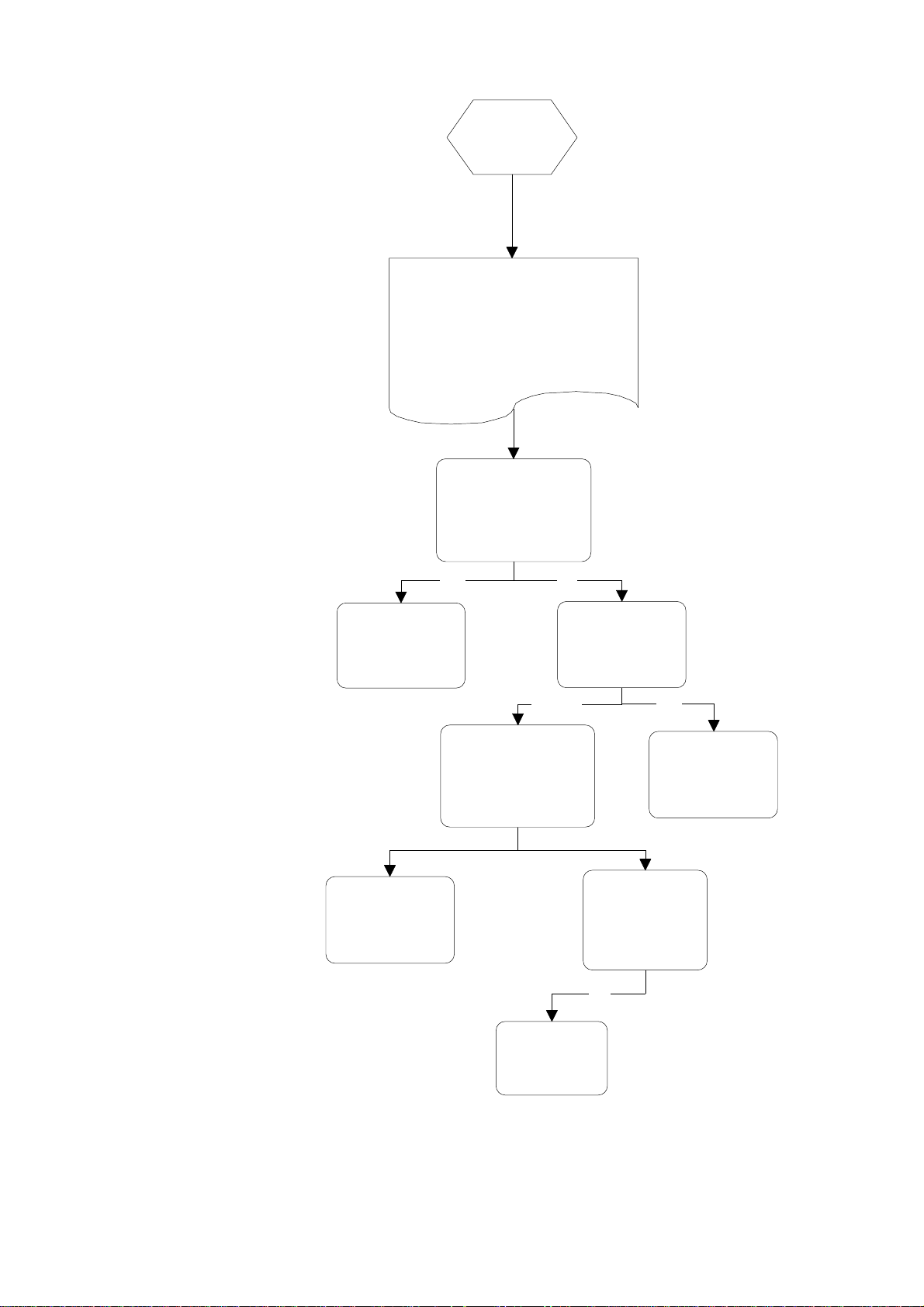
4.4 Diagnostics Quick Reference Flow Chart
again you will remove
Start/Pause buttons
previous fault code will
LCD
test mode
mode
Press and hold
Keylock, then
for 6 seconds
#1 Display
Press Power
button
#2 Show Off/Demo Mode
Press Power
Button
#3 Hardwre Output Test
LED Heavy Normal Light Delicate
EU Off Off Off On
FU Off Off On Off
dd Off Off On On
LS Off On Off Off
rd Off On Off On
P1 Off On On Off
P2 Off On On On
dF On Off Off Off
Er On Off Off On
temp On Off On Off
All LED's &
LCD segments
except Keylock
are illuminated
Press
Start/Pause
button
Press
Start/Pause
button
Press
Start/Pause
button
Press Keylock
button to turn
output On/Off
Initiate Pen upload via
Rinse program LED.
At the same time, first
the current, then the
be displayed in the
Cycles
through every
LED & LCD
segment
Hardware
output
diagnostic
EU = Exhaust valve
FU = Water Inlet Valve
dd = Detergent diverter valve
Er = Element relay
LS = Lid seal pump
rd = Rinse aid dispenser
P1 = Wash pump motor
P2 = Drain pump motor
dF = Drying fan
temp = currentwater temperature
Display green = output on
Note:
Display red = output off
Tub microswitch can be tested at
any time. Rinse LED on = Open
Rinse LED off =Closed
To clear the current
fault code press the
Keylock once. Note if
you press Keylock
the previous fault.
Disconnect
power supply to
exit Show Off
See Next
- 18 -

4.4 Diagnostics Quick Reference Flow Chart cont'd
#4 Continuous Cycle Test Mode
Press Key Lock.
Machine Beeps
Smiley Face off &
Smiley Face on &
water pressure
water pressure
pressure setting to 'LP'.
LCD is Rd backlight
Press Power
Button
Press
Start/Pause
button
Once a mode has been entered, press Power to exit diagnostics
except Display and Show Off modes) which require the plug to be removed from the power socket.
Continuous
cycle
Stand - by
mode
and displays CC.
Touchswitch panel is
Red Red Red Red
Select desired cycle and
operate as normal.
Continuous cycle is indicated
by backlight alternating
between green & orange. In
this mode the cycle count is
displayed.
Rinse Aid Adjustments/Tub Open Beep/Water Pressure Setup
LCD Display on. Hold
the Programme and
Eco Touch Switches
simultaneously for
5 seconds
Water Pressure option
is available if water
pressure is below
50kPa and a 'U1'fault
occurs during wash
cycles. If this happens
then change water
Press Key Lock
Press
Start/Pause
and "HP" is
displayed in
the LCD.
This turns the
deactivates Tub
Open
beeps.
This turns the
activates Tub
Open
beeps.
This adjusts
set up from high
to low.
Push Wash
Programme Selection
Touch Switch to select
dose of Rinse Aid.
Each LED = 1cc.
Press Power to Exit.
Press Power to
exit
(Factory setting is 'HP'.)
Press
Start/Pause
This adjusts
set up from
low to high
- 19 -

4.5 Fault Codes
Fault Code LED Display Fault Possible Causes
F1 ----# The flood switch has
been activated.
F2 ---#- The motor is not
rotating.
F3 ---## The water temperature is
greater than 80°C.
F4 --#-- No temperature increase
has been recorded when
the element is on.
F6 --##- Communications Baud
rate error.
F7 --### Communications Time-
Out error.
F8 -#--- RAM fault.
• A leak has occurred in the base of
the dishwasher.
• The fill valve has failed open.
• The flood switch is faulty.
• Excessive water has been added
to a wash sub cycle, indicating
leaking seal or siphoning.
• Foreign matter has jammed the
motor.
• The motor drive electronics or
power supply have failed.
• The rotor is faulty or missing.
• The hall sensor is faulty or
missing.
• The element has failed on.
• The temperature sensor has failed.
• The electronics ADC has failed.
• The incoming water temperature
is greater than 80°C.
• The element is not connected.
• The element has gone open
circuit.
• Temperature sensor or electronics
ADC has failed.
• The motor control micro has
communications set at an
incorrect baud rate.
• Communication echo bytes are
consistently incorrect (perhaps
due to noise).
• External master device has
incorrect baud rate.
• The motor control micro has
crashed and is not responding to
communications requests.
• The hardware communications
link from console to motor micro
has broken.
• An external device is holding the
communications line low.
• The electronic controller has
RAM fault.
- 20 -

Fault Code LED Display Fault Possible Causes
U1 #---# Fill fault. The motor has
not primed after a given
time.
U2 #--#- Tub open fault.
U3 #--## Time to fill was too
short, indicating water
was still in the tub.
• The water supply is not turned on.
• The machine is siphoning.
• The sprayarm is not in place.
• Excessive foaming.
• The fill valve has failed closed.
• The machine is set to 'HP' on a
low pressure water supply.
• The drawer has been forced open
during a wash cycle.
• The drawer microswitch has
failed.
• The exhaust valve has failed open
circuit.
• Drain pump is blocked.
• Drain hose is blocked.
• Sprayarm or rotor not turning
freely.
• Motor electronics have failed.
• Machine set to 'LP' on a high
pressure water supply.
- 21 -

F1
Monitored while mains
power is on. When one
drawer leaks this cuts out
both drawers. F1 is not
monitored in diagnostics.
Does the water
through the
back air vent?
No Yes
Look for a leak
from the lid, tub
& hoses (refer
Page 32)
No
Check the spray
arm for a split or
water deflection
Not OK
overflow
Check the fill valve
for an electrical or
Yes
Is the water level
in the tub above
the spray arm?
Note*
Yes
mechanical fault
OK
Did a flood
occur & activate
the flood switch?
No
Has the switch or
polystyrene float
been mislocated
No Yes
Check the flood
switch wiring and
switch for a
closed circuit
Not OK
No
Machine may be
syphoning and has
topped up too
many times
Check non-return
valve and drain
hose height
Was the
machine
tilted?
Yes
Check load
Replace
valves
Note: Has the spray arm floated off
affecting load sensing or is the product
programmed for low pressure fill on a high
pressure installation? Reprogramme?
sensing through a
serial download
connection
Test the flood
switch connections
for a closed circuit
OK Not OK
Repair the
wiring or
connections
- 22 -
Relocate float
Replace the
flood switch
F2
This fault is monitored when the
motor is running. It is looking for 10
stalls in a row. It is not monitored
during diagnostics.
The rotor has not
been sensed as
rotating. Is the rotor
jammed?
Note*
Yes No
Free or replace
the rotor. Check
the rotor housing.
Repair or replace
wiring,
connections or
stator.
*Note: Has the spray arm caused the
rotor to jam by being interfered with by
an object falling through the basket?
Not OK
Check the stator
connections and
wiring. See
specification chart for
stator readings.
Not OK
Replace the
RPS.
Substitute Rotor
OK
Replace Rotor
OK
Substitue the
rotor position
sensor on the
stator.
OK
- 23 -

F3
This fault is monitored
every 6 seconds while the
mains power is connected.
It is not monitored during
diagnostics.
Water sensed
at greater than
80°C
Yes
Replace the
electronic
controller
Is the element
on all the
time?
Check the wiring &
connections to the
element and sensor
PCB
Not OK OK
Is the incoming
No Yes
water greater
than 80° C?
No
Turn the power
off at the supply
and then retest
Is the element
heating all the
time?
Adjust the
incoming water
temperature
YesNo
Repair or replace
the wiring or
connections
Replace the
heater plate
Check the
resistance of the
sensor at the PCB.
See chart.
Not OK
- 24 -
Replace the
electronic
controller

F4
No temperature
increase has been
sensed while the
element is on.
Does the
element heat in
diagnostics?
Test the resistance
of the element at the
controller as per the
specifications
Not OK OK
Test the edge
connectors
and wiring
OK
Test the
resistance at
the element
Not OK
NO YES
Turn the power to
the dishdrawer off
at the supply. Then
retest.
Repair the
wiring or
connections
Test the resistance
of the sensor as per
OK Not OK
Replace the
electronic
controller
the temperature
chart
Check the wiring
and connections
to the sensor
OK
Replace the
Heater Plate
Not OK
Replace the
element plate
- 25 -

F6
F7
Inter-communication fault.
Replace the electronic
controller. If this occurs while
you are servicing the
Dishdrawer, you may have
induced the fault , so ignore it.
F8
RAM fault.
Replace the
electronic
controller
- 26 -

U1
which time the fill valve operates
valve activate in
at the controller to
wiring and valve.
resistance of the
Replace the valve.
repair the wiring
No
No
Motor runs for 15 seconds, during
for 2 seconds. This occurs three
times. If prime is not detected
then the fill valve is operated
continually until prime is reached.
Is the water
pressure
above 50Kpa?
Yes
Does the water
diagnostics?
Yes
Sprayarm not
in place.
OK
Not OK
Below 50kPa water
pressure change the
programme from
'HP' to 'LP' as per
Page 14
Check the voltage
the valve. 24vdc
Not OK
Replace the
electronic
controller
Refit spray
arm
OK
Is the tap turned
on or the water
inlet filters
blocked?
Check the
continuity of the
OK
It must have a
mechanical fault.
OK
Not OK
Check for a
kinked hose
Check the
valve at the
valve.
Not OK
Replace the
valve.
Check and
or connections
OK
The wash
impellor is
slipping or
missing
OK
Machine
siphoning
Not OK
Not OK
Replace the
rotor
assembly
Check the
drain length
and height
OK
- 27 -
Foaming
Check for
incorrect use of
detergent or
rinse aid leak.

U2
The tub drawer has been
working in
No
sensed as open during
the cycle or the exhaust
valve is open circuit.
Is the drawer
open?
Yes
Shut the drawer.
Check the
mechanical
operation of the
the slides.
OK Not OK
Test the exhaust
valve for an open
circuit.
Note: Tub home microswitch is located on the rear
of the left slide runner and is connected in series with
the exhaust valve.
Check the
microswitch is
diagnostics.
OK Not OK
Replace the
microswitch.
Adjust the slides.
- 28 -

Check locknut on
filter plate is
locked in
correctly
U3
The motor has sensed
prime too quickly
Has the
dishdrawer
drained?
No Yes
Check for pump
blockage or drain
impellor failure
Free sprayarm
or rotor
Check the
rotor/sprayarm
are turning freely
Not
OK
OK
Possibilty of
electronics incorrectly
sensing the load but
not likely
Has it been
programmed for low
pressure? Refer
Page 14 for
Re-programming.
- 29 -

Poor Dry
Performance
Rinse aid not
being
dispensed
In Diagnostics, does
the Dispenser pump
run?
Is there rinse aid in
the dispesner?
OK
Replace dispenser.
Yes
Repair wiring or
connection.
Replace dispenser.
No
Check the continuity of
the wiring and pump
solenoid by removing
the connections at the
PCB and testing with a
meter.
Not
OK
OK
OK
Check the voltage
(24 Volts dc) at the
PCB.
Not
OK
- 30 -
Replace the PCB

water now exits the other side of
Test voltage at
Check the continuity of the
wiring and diverter solinoid
Not OK
No
Poor Wash
Performance
Detergent not
flushing out of
Pre Wash or Main
Wash chambers
In Diagnostics active the fill valve
and note which side of the
dispenser the water comes out.
Then turn off the fill valve and
activate the diverter valve(dd),
re-active the fill valve to see if the
the dispenser.
OK
Not OK
Replace
dispenser
by removing the
connections at the PCB.
and testing with a meter.
OK
the PCB
(24 volt)
Not OK
- 31 -
Replace
Electronic
PCB
Remove drawer
fronts and note
that this happens
during cycle
Yes
May have
intermitent
bockage in
dispenser

Enter Diagnostics
must reach between
connection. Pressure
joints for leaks
OK
Not OK
and seal for correct
Tub Lid
No
Leak
Fit test
gauge to Air
pump
and activate
Exhaust valve
then air pump
Run pump for 60
seconds. Pressure
30 - 40 Kpa.
Switch
Pump off
Leave for 2 min.
Is there a
pressure loss?
No
Check lid & tub for
correct alignment
installation.
Yes
Check the lid
gasket and
Yes
Pinch plumbing
above the exhaust
valve connection.
Pressure creases?
No
Yes
Pinch plumbing
above the test gauge
creases?
Replace
Exhaust
Valve
Replace air
pump
- 32 -

5.0 WIRING DIAGRAM
- 33 -

6.0 SERVICE PROCEDURES
6.1. Drawer Front Removal
6.1.1 Slide open drawer.
6.1.2 Locate draw pin on either side of the tub.
6.1.3 Using a sharp pair of long nose pliers or slip jaw pliers grasp the
center dividing web of the pin and pull away from the tub to remove
the pin.
Support the drawer front with your hand while doing this.
Note: The pin web is vertical.
6.1.4 With both pins removed the bottom of the drawer front can now be
eased down and forward so as to clear the microswitch lever.
6.1.5 Now carefully pull the drawer front down to allow it to come free
from the top locating slots.
6.1.6 This allows the drawer front to come away with the handle insert and
insulation.
6.1.7 Refit in reverse manner insuring the drawer slides are right forward
and the pin secures through the hook on the front end of the slide.
Note: When reinserting the pins make sure the dividing web is
vertical.
6.2. Handle and LCD Display Removal
6.2.1 Remove the drawer front as per instructions in 6.1.
6.2.2 The handle clips under two location inserts either side of the tub. Pull
forward on the handle tabs and this will release them from the
location inserts.
6.2.3 Disconnect the seven wire harness from the electronic controller to
the LCD or Badge.
6.2.4 The handle may now be lifted clear.
The LCD display is held in place by a spring tab on one end. Using a
small blade screwdriver slip it down the end of the LCD with the
single tab. This will release the LCD.
6.2.6 The wiring harness can now be unplugged from the LCD.
6.2.7 Push pads can now be removed. The LCD display holds these in
place.
6.2.8 Refit in reverse manner.
6.3 Drying Fan Removal
6.3.1 Remove the drawer front as per instructions in 6.1.
6.3.2 Slide forward the drying fan duct and remove.
6.3.2 Disconnect the two wire harness from the electronic controller
6.3.3 Release the three securing tabs that hold the drying fan in place while
applying forward pressure on the drying fan.
6.3.4 The drying fan will now come free.
6.3.5 Refit in reverse manner.
- 34 -

6.4 Detergent Dispenser
6.4.1 Remove the drawer front and handle as per instructions in 6.1.& 6.2
6.4.2 Disconnect the two wiring loom connections off the dispenser coils.
Note: Push back locking tabs to allow connectors to release.
6.4.3 Unclip the retainer flap at the bottom center of the dispenser and
slide out the rinse aid level LED.
6.4.4 Unclip the fill hose on the dispenser
6.4.5 While holding the dispenser unscrew the six T10 Torx drive screws
securing the brackets around the dispenser.
6.4.6 The dispenser can now be removed from inside the tub.
6.4.7 The coils can be replaced as a spare part by sliding them off the
armature.
6.4.8 To open up the dispenser door fully, first open the door using the
release catch then squeeze the top sides of the door. This will release
the door to the fully open position. This can be done with the
dispenser in place.
6.4.9 Refit in reverse manner ensuring the dispenser gasket is located
correctly.
6.5 Electronic Controller
6.5.1 Remove the drawer front and handle as per instructions in 6.1.& 6.2.
6.5.2 Placing a finger either side of the top sides of the controller, pull it
forward until the controller clears the top edge of the tub.
6.5.3 Disconnect the wiring connectors down the left side of the
controller.
6.5.4 The controller can now be tipped down to 90° from it’s original
position. This will allow the disconnection off the lower wiring
connectors and the two and three wire looms from their wire duct.
6.5.6 The controller can now be lifted clear.
6.5.7 Refit in reverse manner.
6.6 Top Kick Strip Removal
6.6.1 Pull out the lower drawer.
6.6.2 Place both hands under the top kick strip.
6.6.3 Pull the bottom of the top kickstrip forward quickly.
6.6.4 Tipping it right up will allow the top locating tabs to drop out of the
tub inserts.
6.6.5 Refit in reverse manner ensuring it is clipped into place.
- 35 -

6.7 Lower Kick Strip Removal
6.7.1 Remove the top kick strip as per instructions in 6.6.
6.7.2 Insert a flat blade screwdriver into the two inserts in the trim above
the lower kick strip and twist.
6.7.3 This will unclip the lower kick strip from the chassis.
6.7.4 Refit by locating the lower kick strip pins into the chassis clips and
foot retainer clips.
6.7.5 Push on the face of the lower kick strip to locate home the lower
kickstrip pins.
6.8 Wiring Cover Removal
6.8.1 Remove the drawer front as per instructions in 6.1.
6.8.2 Unclip the front two legs of the wiring cover from under the
electronic controller and the front left hand side of the tub.
6.8.3 Release the three clips on the underside of the tub which retain the
wiring cover.
6.8.4 The wiring cover may now be moved forward to release it from the
link assembly at the rear.
6.8.5 To reassemble first ensure that the wiring harnesses, drain hose and
fill hose are clipped into their correct position.
6.8.6 Then refit in reverse manner.
6.9 Filter Plate Removal
6.9.1 Remove the lower racks from the tub.
6.9.2 Remove the drain filter assembly.
6.9.3 Rotate the filter plate locknut anti-clockwise to release the filter plate
from the rotor assembly.
6.9.4 Lift the filter plate clear.
6.9.5 Refit in reverse manner.
6.10 Rotor Assembly Removal
6.10.1 Remove filter plate as per instructions 6.9.
6.10.2 Rotate the rotor locking ring anti clockwise to release it from the
motor assembly.
6.10.3 This assembly is not serviceable.
6.10.4 Refit in reverse manner.
- 36 -

6.11 Tub Removal
6.11.1 Remove the drawer front as per instructions in 6.1.
6.11.2 Remove the wiring cover as per instructions in 6.8.
6.11.3 Disconnect the fill hose from the dispenser (water may drip)
6.11.4 Disconnect the mains harness and chassis harness connectors from
the electronic controller.
6.11.5 Unclip the drain hose cuff from the motor assembly.
6.11.6 From the under side of the tub now unclip the drain hose, fill hose
and the wiring looms which go to the link assembly. Disconnect the
earth wire off the element plate.
6.11.7 The link assembly can now be unhooked from the rear of the tub by
pressing the spigots back through the tub connection point.
6.11.8 The tub may now be lifted at the front and slipped forward off the
slide runners.
6.11.9 Refit in reverse manner.
6.12 Locking Ring, Element Plate and Motor Assembly Removal
6.12.1 Remove the drawer front, tub, filter plate and rotor assembly as per
instructions in 6.1,6.9, 6.10 & 6.11.
6.12.2 Disconnect the wiring connectors off the heater plate and motor
(mark motor wire location). To release the motor connections push
a fine blade screwdriver down alongside the wiring connection to
release the locking barb on the terminal.
6.12.3 Disconnect the rotor position sensor from the motor housing.
6.12.4 While lifting the tab on the locking ring, rotate the ring anticlockwise
until it comes free of tub tabs.
6.12.5 This also releases the motor housing from the locking ring.
6.12.6 Holding the pump housing on the motor assembly lift the locking
ring, heating plate and motor clear of the tub.
6.12.7 The suction pipe of the drain molding will slide out of the tub drain
area.
6.12.8 You may now lift the locking ring clear of the motor assembly. This
will allow the heater plate and motor assembly to come apart
6.12.9 Be careful of the two ‘O’ rings which seal between the motor
assembly and heater plate and the heater plate and tub, these and the
tub sealing area must be clean and put in the correct place before
reassembly takes place.
6.12.10 Check both the drain cuff ‘O’ ring and suction pipe ‘O’ ring for
deformation and damage. Lubricate and if necessary replace ‘O’ rings
before reassembly.6.12.11 Reassemble in reverse manner
ensuring all locking ring tabs are engaged.
- 37 -

6.13 Lid Assembly Removal
6.13.1 Remove tub assembly as per instructions in 6.11
6.13.2 Disconnect the lid plumbing off the exhaust valve and air pump
above the ‘Y’ joint.
6.13.3 Release two locking tabs securing the front of the lid to the chassis.
6.13.4 To do this, push back the tab in the center of the rectangular slot at
the front of the lid molding, using a blade screwdriver, then apply
downward pressure to the lid while holding the tab back.
6.13.5 The lid will now drop into the chassis opening and this will allow it
to be slid forward out of the chassis area.
6.13.6 Refit in reverse manner being careful not to damage the seal when
fitting the lid in through the chassis. Ensure the location tab at the
right rear of the lid locates to the right of the rear chassis support.
Note: The bottom lid has a strengthening bar at the rear.
6.14 Lid Seal Replacement
6.14.1 Remove Lid assembly as per instructions 6.13.
6.14.2 Remove the seal by grasping hold of it in the middle and easing it
away from the lid. This will release the fir tree part of the gasket
from the retaining slot.
6.14.3 Ease the gasket away from the air plumbing connector joint at the
rear of the lid.
6.14.4 Fit the new up to the shoulder on the plumbing connection. Slide
both ends of the lid seal into place ensuring they rest against the
stops.
6.14.5 Lay the gasket in the approximate position around the lid.
6.14.6 Press the gasket into position at each corner. The fir tree section
pushes into the lid slot.
6.14.7 Now the rest of the gasket can be pushed in around the lid section.
Note: This is a push in seal and does not require a sealant.
6.14.8 Testing the gasket with an extension piece of air plumbing, air gauge
and air supply before fitting would be advisable. Pump the gasket up
to 40Kpa and then pinch off the supply. The pressure should not
drop below 30Kpa over a 60 second period.
6.14.9 Refit lid as per instructions in 6.13.6.
- 38 -

6.15 Slide Runner Replacement
6.15.1 Remove the Tub as per instructions 6.11
6.15.2 Bottom slide runners only. Remove the two large Philips head screws
securing the slide runner at the front. The backing plate that the
screws locate into may come loose. This does not matter. It can be
realigned on reassembly.
6.15.3 Tap the slide runner from underneath at the front. This will knock the
slide runner up and free from its location in the chassis.
Note: On the bottom lefthand slide runner the water valve
mounting bracket will come away as well. This will mean
the water and electrical connections will have to be
disconnected first.
6.15.4 The slide runner may now be pulled forward to release it from its
location in the rear of the chassis.
6.15.5 Refit in reverse manner.
6.16 Front Trim Replacement
6.16.1 The trim has to be removed by breaking the retaining clips.
6.16.2 This can be done by slipping a blade screwdriver between the trim
and the chassis and twisting the blade to snap the clips. Protect the
cabinet from chipping and remove the broken clips.
6.16.3 Line up the clips on the replacement trim with the holes in the chassis
and push home.
6.17 Sound Gasket Replacement
6.17.1 Remove the sound gasket by grasping it in the middle with your
fingers and pulling it out of the trim.
6.17.2 To refit, feed the ends of the sound gasket into the ends of the
trim slot.
6.17.3 Push the middle section of the sound gasket into the slot then work
the rest in.
6.17.4 Roll the sound gasket with a coin to get it even.
- 39 -

6.18 Link Assembly Removal
6.18.1 Remove tub as in instructions 6.11.
6.18.2 Release clips on side of link assembly to allow the lid of the assembly
to hinge open.
6.18.3 Using a blade screw driver to wedge out the spigots in the hinge
point of the bracket connecting to the rear of the dishwasher.
6.18.4 With both assembly lid open and the hinge point free the assembly
may be released from the drain hose, fill hose and wiring harnesses
(mark on the harnesses and hoses the location of these to the lid so
that when reassembling they are put back in the same location).
6.18.4 To replace the link assembly bracket, release the wire and hose
retaining clip to free these items, then slide the bracket up and out of
rear panel.
6.18.5 Refit in reverse manner.
6.19 Air Pump Removal
Note: This component maybe serviced by two Methods.
6.19.1 Method 1: Remove appropriate tub assembly as per instructions in
6.11.
6.19.2 Method 2: Remove lower kick strip as per instructions in 6.7
6.19.3 Remove the clip pegs from the slide retainers.
6.19.4 Slide the dishdrawer from the cavity to allow servicing from the rear.
6.19.5. Remove the screw securing the rear service panel.
6.19.6 Fit a screwdriver through the hole in the rear service panel and
lift or tap the shaft of the screwdriver up so to disengage the panel
from its retainers.
6.19.7 The service procedures from now on are the same for both methods.
6.19.8 Disconnect the air plumbing from the air pump.
6.19.9 The air pump can now be released from the rubber mount (if sliding
the rubber mount off the exhaust valve be careful not to lose the steel
core which will fall out of the exhaust valve. The exhaust valve core
is fitted with the rubber end upper most ).
6.19.10 Disconnect the wiring connector from the coil.
6.19.11 Refit in reverse manner. Ensure the pump hangers are correctly
located.
- 40 -

6.20 Exhaust Valve Removal
Note: This component maybe serviced by two Methods.
6.20.1 Method 1: Remove tub assembly as per instructions in 6.11.
6.20.2 Method 2: Remove lower kick strip as per instructions in 6.7.
6.20.3 Remove the clip pegs from the slide retainers.
6.20.4 Slide the dishdrawer from the cavity to allow servicing from the rear.
6.20.5 Remove the screw securing the rear service panel.
6.20.6 Fit a screwdriver through the hole in the rear service panel and
lift or tap the shaft of the screwdriver up so to disengage the panel
from its retainers.
6.20.7 The service procedures from now on are the same for both
directions.
6.20.8 Lift the exhaust valve up to disengage the mounting from the
chassis.
6.20.9 Disconnect the air plumbing from the exhaust valve.
6.20.10 Remove the exhaust valve from the rubber mount (be careful not to
lose the steel core which will fall out of the exhaust valve. The
exhaust valve core is fitted with the rubber end upper most).
6.20.11 Disconnect the wiring connection from the exhaust valve.
6.20.12 Refit in reverse manner. Ensure the pump hangers are correctly
located.
6.21 Water Valve Removal
6.21.1 Remove the lower tub as per instructions in 6.11.
6.21.2 The water valve is located at the rear on the lefthand side.
6.21.3 Disconnect the wiring connections to both solenoids. Release the
locking tabs for the connectors with a blade screwdriver while doing
this.
6.21.4 Disconnect the inlet hose connection.
6.21.5 The water valve may now be slid forward off the mounting bracket.
6.21.6 Disconnect the two fill hoses off the valve noting which hose goes to
the top and tub and which goes to the bottom tub.
6.21.7 Refit in reverse manner.
6.22 Flood Switch Removal
6.22.1 Remove the lower tub as per instructions in 6.11
6.22.2 The flood switch is located on the base of the chassis.
6.22.3 Remove the wiring connections to the switch noting each connection
location.
6.22.4 The switch is released from the chassis by squeezing together the
pins on the legs of the switch with a fine blade screwdriver.
6.22.5 Refit in reverse manner.
- 41 -

6.23 EMI Filter Removal
6.23.1 Remove the lower tub as per instructions in 6.11.
6.23.2 The EMI filter is located at the rear left hand side of the chassis base.
6.23.3 Remove the screw in the rear access panel of the chassis..
6.23.4 Raise the insulating cover to expose the EMI filter.
6.23.5 The EMI filter can now be replaced or serviced.
6.23.6 Refit in reverse manner.
6.24 Tub Microswitch Removal
Note: Located on the rear of the left slide runner and connected in series
with the exhaust valve, this component can be serviced by two
methods.
6.24.1 Method 1:
Remove the slide runner as per instructions in 6.15.
6.24.2 Method 2:
Remove lower kickstrip as per instructions in 6.7.
6.24.3 Remove the clip pegs from the slide runners.
6.24.4 Slide the DishDrawer from the cavity to allow servicing from the
rear.
6.24.5 Remove the screw securing the rear service panel.
6.24.6 Fit a screwdriver through the hole in the rear service panel and lift or
tap the shaft of the screwdriver up so as to disengage the panel from
its retainers.
6.24.7 The service procedures from now on are the same for both methods.
6.24.8 Disconnect the wiring to the microswitch.
6.24.9 Release the microswitch from the retaining clips on latch retaining
mechanism on the drawer slide.
6.24.10 Refit in reverse manner.
- 42 -
 Loading...