


Integrated panel preparation
DS605I and DD605I models
DishDrawer
NZ AU GB IE
Safety and warnings
WARNING!
Cut Hazard
Take care - panel edges are sharp.
Failure to use caution could result in injury or cuts.
Important!
Read these instructions completely and carefully.
Ensure the product is not plugged in.
Installation of DishDrawer® panels requires basic mechanical and electrical skills.
Installation must comply with your local building and electricity regulations.
Failure to install the DishDrawer panels correctly could invalidate any warranty or liability
claims.

Contents
Double models
Product preparation
Single models
Product preparation
Panel Installation
Badge cut-out, handle and mounting bracket
Securing the mounting brackets
Reconnecting the wires and fitting the
panels and a custom toe kick (double models only)
2
4
6
7
8
1
Important!
SAVE THESE INSTRUCTIONS
The models shown in this User Guide may not be available in all markets and are
subject to change at any time. For current details about model and specification
availability in your country, please go to our website www.fisherpaykel.com or
contact your local Fisher & Paykel dealer.
2
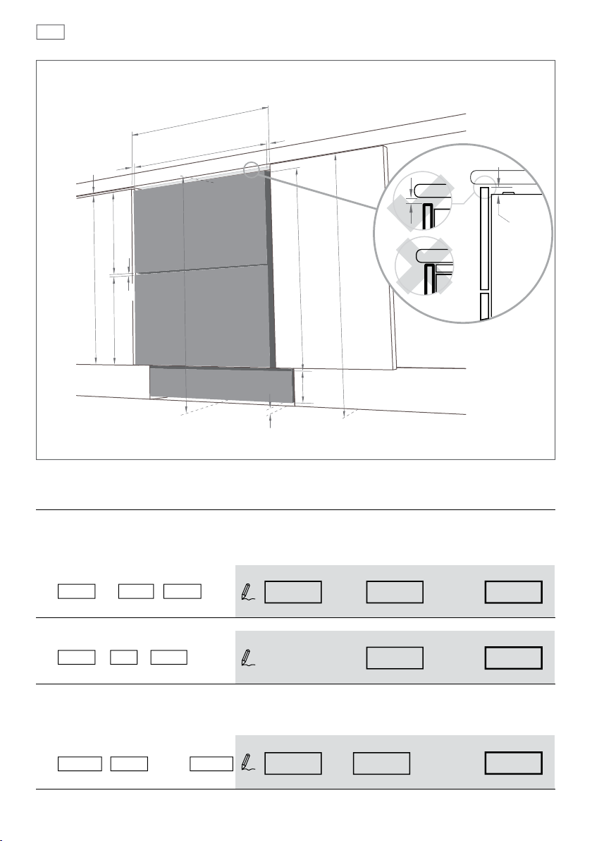
Product preparation
Double DishDrawer models
A
width of ALL panels
min. 2.5 mm
min. 5 mm
upper
panel
height of
upper panel
C
height of
lower panel
8 mm
Air gap
lower
panel
819.5 - 879.5 mm
min. 2.5 mm
D
735 mm
min.
5 mm
B
min.
12 mm
height of
toe kick
panel
toe kick panel
Installation diagrams for illustration purposes only
The following calculations assume the top of the upper panel is aligned with the top of the
adjacent cabinetry. The nal panel/cabinetry alignment is achieved by adjusting the feet:
width of ALL panels
Measure
then complete the equation.
i.e 600 mm - 2 x 2.5 mm = 595 mm - 2 x =
A (
the width between adjacent door/drawer fronts) and write it in the rst box below,
door clearance panel width
A
A
width ALL panelsdoor clearance
(min. 595 mm)(min. 2.5 mm)
height of upper panel
standard height
i.e 398 mm + 0 mm = 398 mm 398 mm + =
B
height
upper panel
B door extension
height upper panel
(min. 595 mm)(0 mm recommended)
height of lower panel
Measure
then complete the equation.
i.e 717.5 mm - 398 mm - 8 mm = 311.5 mm - - 8 mm =
C (
door/drawer height (or equivalent)) and write it in the rst box below,
C
height
upper panel
Air gap
height
lower panel
C
(min. 717.5 mm + B)
height upper panel
Air gap
height lower panel
(min. 311.5 mm)
Note: The ‘door extension’ B allows for the top of the upper panel to be above the DishDrawer® where required.

Product preparation
Toe kick preparation
height of toe kick panel
3
Measure
D (
height from the top of adjacent cabinet door fronts to the oor) and write it in the rst
box below, then complete the equation.
D
i.e 817.5 mm - 0 mm - 735 mm - 12 mm = 70.5 mm - - 735 mm - 12 mm =
B
height
toe kick panel
D
height adjacent
cabinetry
B
door
extension
DishDrawer®
dimension
min. clearance
toe kick panel
Toe kick options
The black prefinished toe kick panel is
supplied. This panel can also have a front panel
of your choice attached to it using screws or an
adhesive.
A toe kick panel of any material with thickness
9 - 19 mm can be screwed to the plastic toe
kick mounting bracket (supplied).
55 mm
432 mm
R12.7 mm
Integrated Panel material
max.
16 -20 mm panel thickness
Adequately sealed to withstand moisture (50
O
C @ 80% RH)
67 mm
Parts supplied
Toe k ick
mounting
screws (5)
Mounting
bracket (2)
height
(min. 70.5 mm)
67-127 mm
Panel mounting
screws (12)
Integrated door seal (2)
Integrated rectangular badge (2)
(Satin chrome supplied)
Toe kick mounting
bracket (1)
Prefinished Toe kick panel (1)

4
Product preparation
Single DishDrawer models
A
min. 2.5 mm
min. 5 mm
B
9 mm
Air gap
width of panel
panel
height of panel
Air gap
min. 2.5 mm
min.
5 mm
9 mm
Installation diagrams for illustration purposes only
The following calculations assume the top of the panel is aligned with the top of the adjacent
cabinetry:
width of the panel
Measure
then complete the equation.
i.e 600 mm - 2 x 2.5 mm = 595 mm - 2 x =
A (
the width between adjacent door/drawer fronts) and write it in the rst box below,
door clearance panel width
A
A
panel widthdoor clearance
(min. 595 mm)(min. 2.5 mm)
height of the panel
Measure
then complete the equation.
i.e 407 mm - 9 mm = 398 mm - 9 mm Air gap =
Note: when the top of the DishDrawer® has to be lower than the adjacent cabinetry, the panel can be increased
in height.
B (
door/drawer height (or equivalent)) and write it in the rst box below,
B
panel height
Air gap
B
panel height
(min. 398 mm)

Product preparation
Use this diagram if installing the DishDrawer® near floor level.
panel
9 mm
Air gap
O
C @ 80% RH)
Integrated Panel material
16 -20 mm panel thickness
Adequately sealed to withstand moisture (50
9 mm
Air gap
5
Parts supplied
Panel mounting
screws (6)
Integrated door seal (1)
Integrated rectangular badge (1)
(Satin chrome supplied)
Mounting
bracket (1)

6
Badge cut-out, handle and mounting bracket
Installation diagrams feature double models for illustration purposes only
1
Important!
Ensure the product is not plugged in
127 mm
30 mm
25 mm
211 mm
54 mm
127 mm
228.5 mm
Badge zone
228.5 mm
Badge zone
2
3
1
2
1
4

Securing the mounting brackets
3
1
2
7
4
2
1
16 mm x6
Double models only:
Important!
Break off the tab at the top
of the Lower Mounting Bracket
3

8
Reconnecting the wires and tting the panels
and a custom toe kick
5
(double models only)
1
2
6
Important!
Ensure the rubber seal between the
drawer and panels is kept in place
2
16 mm x 5
16 mm x5
1
2

9

Copyright © Fisher & Paykel 2007. All rights reserved.
The product specifications in this booklet apply to
the specific products and models described at the
date of issue. Under our policy of continuous product
improvement, these specifications may change at any
time. You should therefore check with your Dealer to
ensure this booklet correctly describes the product
currently available.
www.fisherpaykel.com
NZ AU GB IE
DishDrawer integrated panel preparation
Published: 06/2007
Part No. 529712 A
 Loading...