

Diagnostic Manual
DishDrawer™
MODELS:
DD605 DS605
Fisher & Paykel Appliances © 2007 - All Rights Reserved
599464

599464 - September 2007
CONTENTS
1 DIMENSIONS & SPECIFICATIONS....................................3
1.1 Product Size (mm)........................................................3
1.2 Specifications...............................................................3
2 OPTION ADJUSTMENT......................................................5
2.1 Changing Setup Options..............................................5
2.1.1 Rinse Aid Setup (rA) ...........................................................5
2.1.2 Water Supply Hardness Setup (hd) (Where Fitted).............6
2.1.3 Auto Power Option (AP)......................................................6
2.1.4 End of Cycle Beeps (EC)....................................................6
2.1.5 Closed Drawer Option (Ld) .................................................7
2.1.6 Clean/Dirty Dish Symbol (dS) .............................................7
3 DIAGNOSTICS ....................................................................8
3.1 DishDrawer™ Diagnostics ...........................................8
3.2 Display/Download Mode...............................................8
3.3 Optical LED Download/Fault Display ...........................8
3.4 Clearing Fault Logs......................................................8
3.5 Hardware Output Diagnostic Test Mode......................9
3.6 Fast Test Cycle ..........................................................11
3.7 Continuous Cycle Test Mode.....................................11
3.8 Temperature & Voltage Display Mode .......................13
3.9 Show Off/Showroom Wash Mode..............................13
3.10 Playing Tunes.............................................................14
4 DIAGNOSTICS QUICK REFERENCE CHARTS ..............14
4.1 Fault Display/Download Mode....................................14
4.2 Hardware Output Test Mode......................................15
4.3 Fast Test Cycle ..........................................................16
4.4 Continuous Cycle.......................................................16
4.5 Temperature & Voltage Display Mode .......................16
4.6 Fault Codes................................................................17
4.7 Fault Code Description Chart.....................................18
4.8 Fault Code Problem Solving Charts...........................22
4.8.1 Poor Dry Performance ......................................................32
4.8.2 Poor Wash Performance...................................................33
5 WIRING DIAGRAM............................................................38
5.1 Power Distribution Concept........................................38
5.2 Wiring Diagram...........................................................39

1 DIMENSIONS & SPECIFICATIONS
1.1 Product Size (mm)
Height (double) 819.5 – 879.5mm
Height (single) 409mm
Width 595mm
Depth 570mm
Drawer Open
(including cabinet) 1090mm
599464
1.2
Specifications
Electrical
NZ/AUS/UK/UE 230-240Volt AC 50Hz 10 amp/5 amp max.
USA 110-120Volt AC 60Hz 10.6 amp/5.3 amp max.
JAP 90-110Volt AC 50/60Hz 11.6 amp/5.3 amp max.
Water Inlet Valves 24Volt DC
65 ± 10 Ohms
2.5 Lt/min (0.65 US gal/min)
Japan only 4 Lt/min
Chassis P.C.B.
NZ/AUS/UK/UE 230 Volt AC
USA/JAP 120 Volt AC
Temperature Sensor 12000 Ohms @ 20
o
C (68oF)
(On Heater Plate) 8300 Ohms @ 30
3000 Ohms @ 60
o
C (86oF)
o
C (140oF)
Drying Fan 2 to 3 Meg Ohms
Motor 80 Volt DC 3 Phase Brushless
Drain 4200 RPM
Wash 2300 – 2850 RPM
Stator 8 ± .5 Ohms per winding
Inlet Hose 1.56m (61 inches)
1000Kpa (145 PSI)
3

599464
Drain Hose 2.01m (78 inches) from rear of cabinet
2.5m (98 inches) bottom tub
2.9m (114 inches) top tub
Detergent Dispenser 24 Volt DC
65 ± 10 Ohms
Rinse Aid Dispenser 24 Volt DC
65± 10 Ohms
Heater Plate (NZ/AUS/UK/UE) 230 Volt AC
Heater Track 50 ± 4 Ohms
Power Supply Resistor 98 +
7 Ohms
Heater Plate (USA) 120 Volt AC
Heater Track 24 ± 3 Ohms
Power Supply Resistor 24 +
3 Ohms
Heater Plate (JAP) 100 Volt AC
Heater Track 20 ± 2 Ohms
Power Supply Resistor 19 +
3 Ohms
Diverter Valve Softener Assy 24 Volt DC
65 +
10 Ohms
Brine Pump 24 Volt DC
65 +
10 Ohms
4

599464
2 OPTION ADJUSTMENT
2.1 Changing Setup Options
To enter the option adjustment mode, press POWER to turn the LCD on, then
hold the ECO button and KEYLOCK button simultaneously for 5 seconds,
ensuring that ECO is pressed first. Once the option adjustment mode is
entered, a beep is emitted and the LCD displays the letters rA. Pressing the
START/PAUSE button scrolls through the options and allows changes as
follows:Rinse Aid Setup (rA).
Water Supply Hardness Setup (hd). (Water softener models only)
Auto Power Option (AP).
End of Cycle Beeps (EC).
Closed Drawer Option (Ld).
Clean/Dirty Dish Symbol (dS).
Integrated and flat door models:- On an integrated or flat door
DishDrawer™ where there is no display, the option chosen is indicated by the
lights showing on the integrated badge as follows:Rinse Aid Setup (red light above START/PAUSE button).
Water Supply Hardness (green light above START/PAUSE button).
Auto Power Option (orange light above START/PAUSE button).
End of Cycle Beeps (green light above START/PAUSE button and ECO light
is red).
Closed Drawer Option (red light above START/PAUSE and ECO light is red).
Clean/Dirty Dish Symbol (not available on Integrated or flat door models).
Dry Enhancement Option (no light above buttons, ECO light is red).
Press POWER at any time to exit this setup mode.
2.1.1 Rinse Aid Setup (rA)
The current rinse aid setting is shown using the red LED’s on the touch switch
panel.
The amount of rinse aid dispensed into a rinse cycle can be varied to suit the
level of hardness of the local water supply. It is adjusted for 1 - 5 dispensing
levels.
(1 = approx 0.5mls (1/10) teaspoon of rinse aid, 5 = approx. 2.5mls (1½)
teaspoon of rinse aid).
5

599464
Press KEYLOCK to advance the rinse aid setting. Once the desired setting is
achieved, press POWER to exit. The rinse aid index is stored in EE memory,
so even with the power removed, the rinse aid level is retained.
2.1.2 Water Supply Hardness Setup (hd) (Where Fitted)
The current supply hardness setting is shown using the red LED’s on the
touch switch panel. One of 5 settings should be selected according to the
known hardness of the supply water. Each setting is appropriate for the
following water supply hardness:
No LED Water Softener turned off, continuous bypass of softener.
1 LED 150-250 ppm water supply hardness.
2 LEDs 250-350 ppm water supply hardness.
3 LEDs 350-450 ppm water supply hardness.
4 LEDs 450-550 ppm water supply hardness.
5 LEDs 550-625 ppm water supply hardness.
Press KEYLOCK to advance the Water Softener setting. Once the desired
setting has been achieved, press POWER to exit.
Selection of a setting affects how the Electronic Controller diverts supply
water, how much water is treated, and how much salt is used in regeneration,
in a manner that optimises the performance of the Water Softener.
2.1.3 Auto Power Option (AP)
The automatic power up sequence that occurs when the tub is opened can be
turned on or off using the KEYLOCK button. If the scrubbing brush symbol is
showing on the LCD, then the auto power up sequence will occur when the
tub is opened. If the scrubbing brush symbol is not showing, then the
DishDrawer™ will not automatically power up when the tub is opened (the
customer will need to press the power button each time they wish to use the
DishDrawer™). Press POWER to exit when the desired setting has been
selected.
2.1.4 End of Cycle Beeps (EC)
The six beeps that occur at the end of the cycle can be turned on or off using
the KEYLOCK button. If the scrubbing brush symbol is showing on the LCD,
then the end of cycle beeps are activated. If the scrubbing brush symbol is
not showing, then the end of cycle beeps are deactivated. Press POWER to
exit when the desired setting has been selected.
6

599464
2.1.5 Closed Drawer Option (Ld)
The closed drawer option can be turned on or off using the KEYLOCK button.
If the scrubbing brush symbol is showing on the LCD, then the closed drawer
option is selected and it will keep the DishDrawer™ locked at all times by
bringing the lid down. When this mode is selected, the customer needs to
press the POWER button to lift the lid whenever they want to open the
drawer. When they close the drawer again, the lid comes down automatically
after 30 seconds and locks the tub. If the scrubbing brush symbol is not
showing, then the closed drawer option is deactivated. Press POWER to exit
when the desired setting has been selected.
2.1.6 Clean/Dirty Dish Symbol (dS)
(Not available on integrated or flat door models)
The clean/dirty dish symbol can be turned on or off using the KEYLOCK
button. If the scrubbing brush symbol is showing on the LCD, then the
clean/dirty dish option is selected. This means that the end of cycle clean
dishes symbol will remain in the LCD display until the power button is pressed
to clear it. If the scrubbing brush symbol is not showing, then the clean/dirty
dish symbol will disappear when the drawer is first opened at the end of a
cycle (factory setting). Press POWER to exit when the desired setting has
been selected.
7

599464
3 DIAGNOSTICS
3.1 DishDrawer™ Diagnostics
Dishwasher Diagnostics can only be entered in Power Off mode, i.e. when
there is no display on the LCD or the badge LED’s are off. Diagnostics is
entered by holding the KEYLOCK and START/PAUSE buttons
simultaneously for 5 seconds. Ensure that KEYLOCK is pressed first.
There are currently four levels of diagnostics. To move to the next level,
press POWER. To enter a level, press START/PAUSE. Once a level has
been entered, pressing POWER will exit diagnostics completely. If no level is
entered, then the display will cycle through the four levels and exit after the
last. On entering diagnostic mode, the first level is the Display/Download
Mode.
3.2
In this mode, all LED’s and LCD segments (except keylock) are illuminated.
3.3
An optical data download is available here to download all EE data to a PC or
Palm PC via the lower tub-home sensor light pipe. Hold the reader pen over
the lower tub-home sensor light pipe and press START/PAUSE to initiate the
download. A short beep indicates the start and finish of download.
The last two faults are displayed on the LCD (secondary control panel LEDs
for integrated and flat door models) during the optical download. The Current
Fault code is displayed first followed by the Previous Fault Code. To read the
Fault Code on the secondary display, refer to Section
3.4
To clear the current fault code, press the KEYLOCK button until a beep is
sounded. This action moves the current fault into the previous fault while
Display/Download Mode
Optical LED Download/Fault Display
4.7 on Fault Codes.
Clearing Fault Logs
clearing the current fault. To clear the previous fault code, press KEYLOCK
once more until the beep is sounded.
Warning: Once a fault code has been cleared, it is permanently removed
from memory and cannot be recovered.
Press POWER to advance to the next level.
8

599464
3.5
This level tests all the hardware outputs and inputs. The LCD display shows
“HO”.
Press POWER to skip hardware diagnostics and advance to the next level.
Press START/PAUSE to enter hardware diagnostics.
Once hardware diagnostics has been entered, the current hardware output
being tested is indicated by letters in the LCD display, and for integrated and
flat door models the LEDs on the touch switch panel using binary encoding,
as shown in the table on the next page.
Different combinations of outputs can be switched on or off together, but the
controller will prevent higher current drawing components such as the wash
pump and the lid motors being turned on together.
Hardware Output Diagnostic Test Mode
Press START/PAUSE to advance to the next hardware output.
Press KEYLOCK to turn the currently displayed output on or off. If the
scrubbing brush symbol (green LED above start/pause button on integrated
and flat door models) is displayed, then that output has been switched on,
and if it is not displayed then that output is off.
Press POWER to exit at any time (all outputs will be switched off on exit).
9
599464
As mentioned on the previous page, the LCD display and touch switch panel
LEDs are illuminated to correspond to a particular hardware device. The
following table details the display order of the test.
Norm
Fast
Deli
Rinse
Hardware Output
LCD
LED
LED
LED
bL Off Off Off
On
Er Off Off
Ld Off Off
On
dd Off
FU Off
P1 Off
P2 Off
On
rd
dF
LE
C1
C2
C3
On
On
On
On
On
On
On
On
On
On
On
On On
Off Off Off Rinse Aid Dispenser (dispenses
Off Off
Off
Off
On
On
Off Off Detergent Diverter Valve
Off
On
On On
Off Off Water Softener Brine Pump
Off
LED
On
Backlight
Off Element Relay
Lid Motors (will run for 10 seconds)
On
Fill Water Valve
Off Motor Wash direction (2300-2850
rpm)
Motor Drain direction (4200 rpm)
current setting)
On
Drying fan
Off Rinse Aid LED
Water Softener Diverter Valve
On
Water Softener Brine Valve
°C
°E
On
On On On
On
Off Displays current water temperature.
Displays controller rail voltage
On On
(C3 is used in the Factory to empty the Water Softener before the Product is
packed.)
WARNING: In diagnostic mode there is no component protection. Therefore
take care when running individual components not to overload them. It is
advisable to avoid turning the element on without placing some water in the
tub first.
NB : No fault codes will come up while in diagnostics mode.
Tub Home Sensor Test:
At any time during HO test mode, the Keylock
symbol on the LCD display (Keylock LED on integrated badge) indicates the
tub position. On
= Closed, Off = Open.
10

599464
3.6
WARNING: Only run this cycle if the DishDrawer™ is connected to the water
supply.
This level runs an 8 minute fast test cycle.
Press POWER to skip Fast Test Cycle and advance to the next level.
Press START/PAUSE to enter Fast Test cycle.
Once Fast Test Cycle is selected the DishDrawer™ goes into standby mode
and 8 minutes will be showing on the display. The test cycle is started by
pressing START/PAUSE, and the following components are run during the 8
minute cycle that follows:- Lid motors, fill valve, wash motor, element, drain
motor, drying fan.
Press POWER to exit at any time.
3.7
Fast Test Cycle
Continuous Cycle Test Mode
In this level the DishDrawer™ can be run continuously in any wash cycle.
Once the cycle has finished, the DishDrawer™ automatically restarts the
same wash cycle.
Press POWER to skip Continuous Cycle. As this is the last level, doing this
will exit diagnostics.
Press START/PAUSE to enter Continuous Cycle.
Once selected, the LCD backlight flashes on and off to indicate the
DishDrawer™ is in continuous cycle and the cycle starts straight away (for
integrated and flat door models the LED above the start/pause button will be
orange instead of green to indicate the DishDrawer™ is running in continuous
cycle). It will run the last cycle that had been selected prior to going into
diagnostics mode.
If it is desired to run a different cycle, exit diagnostics, turn the DishDrawer™
on as normal and select the cycle required. Then turn the DishDrawer™ off
again, re-enter diagnostics and restart the Continuous Cycle as above.
Press POWER to Exit at any time.
11
599464
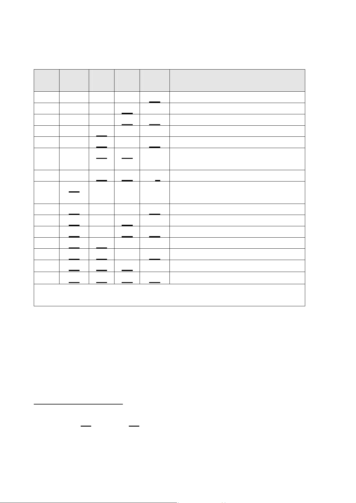
The test sequence in fast cycle mode performs 33 tests. The number of any
failed test is displayed on the touch switch panel LEDs. The test sequence
continues even if a test fails. If there are multiple failures the LEDs will
change during the test.
0 = LED off, X = LED on.
LED Display
H N F D R E
0 0 0 0 0 X 1 Uncontrolled load on PSU (PSU volts < 30 with PSU on and no devices
0 0 0 0 X 0 2 Unrealistic zero crossing time, mains frequency non standard
0 0 0 0 X X 3 Uncontrolled load on PSU (volts dropped when PSU turned off and no
4 Unused
0 0 0 X 0 X 5 Detergent diverter not connected
0 0 0 X X 0 Fill valve not connected
0 0 0 X X X Water softener bypass valve not connected
0 0 X 0 0 0 Rinse Aid pump not connected
0 0 X 0 0 X Water softener brine pump not connected
0 0 X 0 X 0 Fan not connected
0 0 X 0 X X 11 Detergent diverter solenoid low resistance (shorted?)
0 0 X X 0 0 Fill valve solenoid low resistance (shorted?)
0 0 X X 0 X Water softener bypass valve solenoid low resistance (shorted?)
0 0 X X X 0 Rinse Aid pump solenoid low resistance (shorted?)
0 0 X X X X Water softener brine pump solenoid low resistance (shorted?)
0 X 0 0 0 0 16 Fan low resistance (shorted?)
0 X 0 0 0 X 17 Lid motor 1 no current (not connected?) in down direction
0 X 0 0 X 0 Lid motor 1 no current (not connected?) in up direction
0 X 0 0 X X Lid motor 2 no current (not connected?) in down direction
0 X 0 X 0 0 Lid motor 2 no current (not connected?) in up direction
0 X 0 X 0 X 21 Lid motor 1 excessive current in down direction
0 X 0 X X 0 Lid motor 1 excessive current in up direction
0 X 0 X X X Lid motor 2 excessive current in down direction
0 X X 0 0 0 24 Lid motor 2 excessive current in up direction
25-29 Unused
0 X X X X 0 30 Motor FET A phase high side “shorted”
0 X X X X X Motor FET B phase high side “shorted”
X 0 0 0 0 0 Motor FET C phase high side “shorted”
X 0 0 0 0 X Motor FET A phase low side “shorted”
X 0 0 0 X 0 Motor FET B phase low side “shorted”
X 0 0 0 X X 35 Motor FET C phase low side “shorted”
X 0 0 X 0 0 36 Motor phases AB no current (not connected?)
X 0 0 X 0 X Motor phases BC no current (not connected?)
X 0 0 X X 0 38 Motor phases CA no current (not connected?)
X 0 0 X X X 39 Motor phases AB current excessive (shorted winding?)
X 0 X 0 0 0 Motor phases BC current excessive (shorted winding?)
X 0 X 0 0 X 41 Motor phases CA current excessive (shorted winding?)
Test ID Test Description / Probable Cause
turned on)
devices on)
12

599464
3.8
(Not available on integrated or flat door models)
During a wash cycle, the current water temperature or the power supply rail
voltage of the controller can be displayed on the LCD instead of the time
remaining. To enter temperature/voltage display mode, start a wash cycle as
normal. Initiate a keylock by pressing and holding the KEYLOCK button for 4
seconds.
Once in keylock mode, press and hold START/PAUSE for 8 seconds to enter
temperature display mode. The display now alternates between a °C symbol
and the water temperature. Pressing the START/PAUSE again changes the
display to alternate between an °E symbol and the power supply rail voltage
of the controller.
To cancel temperature/voltage display mode, press the POWER button.
3.9
Temperature & Voltage Display Mode
Show Off/Showroom Wash Mode
This mode initiates a shop show off display and wash operation
demonstration.
With the DishDrawer™ powered up and turned on, the show off mode is
entered by pressing and holding the ECO and POWER buttons
simultaneously for 5 seconds. Ensure that ECO is pressed first.
The DishDrawer™ is now in the show off mode and cycles through all of the
LED & LCD segments.
Pressing the POWER button now puts the DishDrawer™ into the showroom
wash mode. Before running this, mode the tub should be filled with water
until it is just touching the underside of the spray arm. The showroom wash is
started by pressing the START/PAUSE button whereby the following cycle is
run:The lid is pulled down.
The wash motor starts and runs for 4 minutes.
The wash motor stops.
The lid is lifted.
The display counts down to zero throughout this cycle.
The DishDrawer™ turns off at the end of this cycle.
13

599464
The DishDrawer™ is still in the Showroom wash mode however, and it can be
re-run by pressing POWER and then START/PAUSE. Once show
off/showroom wash mode has been initiated, the mains power must be
removed to exit out.
3.10
Once in showroom mode, pressing the START/PAUSE button for 3 seconds
will start a tune playing. Pressing the START/PAUSE button again will toggle
the tune between Bach and the Star Spangled Banner. This feature is not
widely known about, may not be present in all models and may be removed in
future products.
Playing Tunes
4 DIAGNOSTICS QUICK REFERENCE CHARTS
4.1 Fault Display/Download Mode
Press and hold KEYLOCK, then START/PAUSE for 5 seconds.
All LEDs & LCD segments except Keylock are illuminated.
Press START/PAUSE.
This initiates pen data download via the lower tub-home light pipe. At the
same time the current and then the previous fault code will be displayed in
the LCD screen and on the secondary control panel LEDs. To read the
fault code on the secondary display, refer to Section 4.7 on fault codes.
Press KEYLOCK.
This will clear current fault code. Note: If Keylock is pressed again, the
previous fault code will be cleared. Pressing Keylock also toggles the wash
icons on the LCD on and off.
Press POWER to exit.
14

599464
4.2
Press and hold KEYLOCK, then START/PAUSE for 5 seconds.
All LEDs & LCD segments except Keylock are illuminated.
Press POWER once.
“HO” will show in the display (integrated and flat door models: Heavy,
Normal, Fast, Delicate, Rinse LEDs showing).
Press START/PAUSE.
Scroll through the following outputs using Start/Pause. Turn the outputs on
& off using Keylock button.
Press POWER to exit.
Note: Scrubbing brush symbol = output on, no scrubbing brush = output off
(on integrated and flat door models a green LED above the start/pause
button is used in place of the scrubbing brush).
LCD Norm Fast Deli Rinse Hardware Output
Display LED LED LED LED
bL Off Off Off
Hardware Output Test Mode
On
Backlight
Er Off Off
Ld Off Off
On
dd Off
FU Off
P1 Off
P2 Off
On
rd
dF
LE
C1
C2
C3
°C
°E
On
On
On
On
On
On
On
On On
On
On On On
On
On
On
On
On
On On
Off Off Off
Off Off
Off
Off
On
On
Off Off Detergent Diverter Valve
Off
On
On On
Off Off Water Softener Brine Pump
Off
On
Off Element Relay
On
Off
On
Off Rinse Aid LED
On
Off
Lid Motors (will run for 10
seconds)
Fill Water Valve
Motor Wash direction (23002850 rpm)
Motor Drain direction (4200
rpm)
Rinse Aid Dispenser
(dispenses current setting)
Drying fan
Water Softener Diverter
Valve
Water Softener Brine Valve
Displays current water
temperature.
Displays controller rail
voltage
Tub Home Sensor test:- Keylock symbol on = tub closed, off = tub open
15

599464
4.3
Fast Test Cycle
Press and hold KEYLOCK, then START/PAUSE for 5 seconds.
All LEDs & LCD segments except Keylock are illuminated.
Press POWER twice.
“FC” will show in the display (integrated and flat door models: Heavy,
Normal, Delicate, Rinse LEDs showing).
Press START/PAUSE twice.
The 8 minute fast test cycle will start.
Press POWER to exit.
4.4 Continuous Cycle
Press and hold KEYLOCK, then START/PAUSE for 5 seconds.
All LEDs & LCD segments except Keylock are illuminated.
Press POWER three times.
“CC” will show in the display (integrated and flat door models: Heavy,
Normal, Rinse LEDs showing).
Press START/PAUSE.
The last cycle that had been selected prior to going into diagnostics mode
will be run continuously.
Press POWER to exit.
4.5 Temperature & Voltage Display Mode
(Not available on integrated or flat door models.)
Start a wash cycle running.
Press & hold KEYLOCK for 4 seconds.
Keylock will be activated.
Press & hold START/PAUSE for 8 seconds.
LCD will now alternate between °C symbol and the water temperature.
Press START/PAUSE.
LCD will now alternate between °E symbol and the controller’s rail voltage.
Press & hold KEYLOCK for 4 seconds.
Keylock is deactivated.
Press POWER to exit.
16

599464
4.6
There are 10 F (fatal) faults, which are displayed in the LCD along with the
symbol of a spanner (not on integrated or flat door models). A fatal fault will
usually require the assistance of a qualified service person.
In addition, there are 4 U (user) faults.
U1 indicates the machine had failed to prime within a certain length of time
usually because the tap has not been turned on. For this reason, at the same
time a U1 comes up in the display we also show the symbol of a tap.
U2 indicates restricted lid travel. The customer can usually rectify a U1 or U2
fault.
A U3 fault is not displayed to the customer, but is recorded in the fault history
and displayed in Smart Tool. It is logged if the motor senses prime in less
than 20 seconds because water was left in the tub from a previous fill, or
Fault Codes
because it has filled too quickly. The product will drain and refill up to 5 times
before logging the fault and continuing on with the cycle.
On a double drawer model, a U4 fault indicates an F fault with the other tub
that has disabled the power supply.
In the Integrated and flat door models, an LCD is not available, and the
presence of a fault is indicated by a red centre (start/pause) LED, with the
fault number indicated by the red LEDs on the touch switch panel.
Once a fault is repaired, it can be cleared by pressing the POWER button. If
the fault is still present, then it will not clear.
A fatal or user fault is accompanied by a continuous pulsating beep, which
can be turned off by pressing either the POWER, START/PAUSE, or KEY
LOCK button. This also stops the drain pump running for an F1 fault.
The last two faults are logged into EE memory.
If a tub is forced open, the product simply pauses as if someone had pressed
the start/pause button.
Except for U4, F1, F3, F8 and F9 faults, the other tub can still be used on a
double drawer model.
17

599464
Once the fault has been cleared for an F3, F8 or F9 fault, the power needs to
be disconnected and reconnected to reset the isolation relay before the
product can be used again.
4.7
Fault Code Description Chart
The following chart is a quick reference guide on fault codes. To read a fault
code off an integrated or flat door model, refer to the LED Display column on
the chart below. The LED that has activated on the secondary display
indicates which fault code has occurred.
To make diagnostics easier, a test handle can be made for use on integrated
or flat door models using a cut down handle and a DD605 PCB LCD. This will
not be able to be used on DD603 products, nor can a DD603 test handle be
used on DD605 products.
Fault
Code
F1 Rinse LED. The bottom
LED
Display
Fault Possible Causes
• Lid not closing.
controller flood
sensor
detector has
been activated
for more than
six seconds.
• Overfilling.
• Foaming.
• Not draining.
• Lid seal damaged.
• Dispenser or water softener or
their seals leaking.
• Damaged water inlet or drain
hoses.
• Leaking heater plate or motor
seals, or drain o-ring seals.
• Yoke jammed or broken.
• Inlet hose to inlet valve
connection loose.
• Inlet valve body leak.
• Heater plate damage (chipped
enamel).
• Dry F1 – PCB mains filter,
harness or connectors,
electronic controller.
18

599464
Fault
Code
F2 Delicate
LED
Display
LED.
The controller
has not
sensed the
motor rotating.
F3 Delicate
and Rinse
The water
temperature
Fault Possible Causes
• Foreign object has jammed the
rotor.
• The rotor has failed.
• Hall sensor connector or wiring
fault at hall sensor or
controller.
• The hall sensor has failed.
• Motor stator winding or
connection open circuit.
• The electronic controller has
failed.
• PCB mains filter has failed.
• The incoming water is greater
°
than 85
C (185°F).
LEDs.
has been
sensed as
greater than
°
85
C (185°F).
F4 Fast LED. No
temperature
increase has
been sensed
for about 4
hours while
the element is
on.
F5 Fast and
Rinse
LEDs.
Lid motor
current too
high during
• The element has failed closed
circuit.
• The temperature sensor on the
heater plate has failed.
• The electronic controller has
failed.
• The element is not connected.
• The element has failed open
circuit.
• The temperature sensor has
failed.
• The electronic controller has
failed.
• Lid jammed up or down.
• The electronic controller has
failed.
F6
Fast and
Delicate
LEDs.
start.
Lid motors ran
but did not
reach stall
current.
19
• Lid actuator off yoke or slide.
• Yoke off lid.
• Faulty lid actuator.

599464
Fault
Code
F7 Fast,
LED
Display
Delicate
and Rinse
Fault Possible Causes
No lid motor
current
detected.
LEDs.
F8
F9 Normal and
Normal
LED.
Rinse LED.
Earth leakage
fault.
Power supply /
controller fault.
• Lid actuator not connected.
• PCB mains filter and controller
connectors.
• Faulty PCB mains filter.
• Faulty electronic controller.
• Test for earth leakage.
• Connectors and earth
connections fitted correctly.
• Damaged harnesses.
• Water damaged harness,
connector, or controller.
• Caused by F3, F8 or F9 faults.
• Check coils and motor
windings.
FF
Normal,
Fast,
Delicate
and Rinse
LEDs.
Top tub not
responding.
• Check lid actuators.
• Check controller for signs of
damage.
• Check PCB mains filter and
controller connectors.
• Check heater plate harness
and connectors.
• Replace electronic controller.
• Replace PCB mains filter.
• Chassis harness or
connectors.
• Faulty top controller.
• Faulty PCB mains filter.
20

599464
Fault
Code
U1 Heavy and
LED
Display
Rinse LED.
Machine has
failed to prime
with water
within approx.
3 minutes.
Fault Possible Causes
• The water supply is not turned
on.
• Low water pressure.
• Blocked water softener if fitted.
• The inlet valve has failed.
• The machine is siphoning.
• The spray arm is not in place,
or the flapper is jammed.
• Excessive foaming - using
tablets (not EU/GB), liquid
detergent or spilled rinse aid.
• The motor has failed.
• Rotor not fitted correctly or
faulty.
U2
U3
U4
Heavy and
Dry LEDs.
Not
displayed to
customer.
Heavy and
Fast LEDs.
Restricted lid
travel, the lid
has reached
stall current
too soon.
Water filled too
quickly, or tub
failed to drain.
Advisory only
– the other tub
has a fault and
has disabled
the power
• The electronic controller has
failed.
• Dishes or cups / glasses
prevent the lid from closing.
• Lid, lid actuators or yokes
jammed.
• Not draining completely from
previous fill.
• Excess water pressure.
• Faulty fill valve.
• Diagnose and repair the fault
in the other tub.
supply.
21

599464
4.8
Fault Code Problem Solving Charts
The following charts can be used as a guide to help locate faults in a
DishDrawer™.
F1 Flood Detected
The bottom controller flood detector circuit has been activated.
The product will abort the wash program, log the fault, start the drain pump,
and report to the user.
Neither tub can be used until the fault is cleared.
PRIMARY ACTION
- Determine if a flood actually occurred? Is there water in the base of the
machine?
SECONDARY ACTION
If water in base.
- Determine where the water has come from, check the following:
Check for the lid not closing (lid actuators), overfilling (spray arm correctly
fitted and flapper shutting off, rotor correctly fitted) or foaming (rinse aid spill
or wrong detergent (liquid or tablets) used, not draining (rotor or motor
housing damaged, drain hose blocked / crushed), lid seal damaged,
dispenser or water softener seals leaking, damaged fill or drain hoses, tub
leaking around heater plate or motor seals, drain hose o-ring at connection
to motor, yoke pegs broken or yoke jammed at front or rear, oversize
dishes, inlet hose connection to water inlet valve leak (washer not fitted,
connection not tight) water inlet valve not shutting off.
- Mop up water in the chassis base before attempting to restart.
TERTIARY ACTION
If no water in base
- Check the chassis harness connection to the PCB mains filter.
- Check for corrosion/dirt around the flood sensor on the side of the mains
filter housing.
- Replace the PCB mains filter.
22

599464
F2 Motor Not Rotating
The controller has not sensed the motor rotating.
The product will pause the wash program, log the fault, and report to the
user.
PRIMARY ACTION
- Check the rotor is free to turn.
- Check that power is available at controller (e.g. do the lid actuators run in
diagnostics).
SECONDARY ACTION
- Check whether the rotor is not moving or is vibrating in diagnostics.
- If vibrating, check the hall sensor is properly fitted, check that the motor
stator connections are OK.
- If not moving, check the connections at the controller and the motor.
- Check the resistance of the motor windings.
TERTIARY ACTION
- Check if a replacement hall sensor solves problem.
- Check if a replacement controller solves problem.
- Check if a replacement PCB mains filter solves problem.
23

599464
F3 Water Temperature Measurement Exceeds 85 Degrees Celsius
The water temperature is sensed at greater than 85 degrees C / 185 degrees
F.
The product will abort the wash program, log the fault, report to the user, and
disable the power supply.
Note: The isolation relay will be disabled. Power to the product will need to
be disconnected then reconnected for it to become fully functional again.
PRIMARY ACTION
- Check the incoming water temperature is not too hot.
- Check the temperature reading in diagnostics, and if 199, ensure the
power connector is properly fitted to the controller and the connector on
the heater plate is correctly fitted.
SECONDARY ACTION
- Check the resistance between pins 1 and 2 of the controller power
connector is about 10K at approx. 25
o
C / 77oF ambient room temperature.
- If not (provided the harnesses are ok and the connectors are correctly
fitted), replace the heater plate (bad temperature sensor).
TERTIARY ACTION
- Check that the temperature reading in diagnostics is the same as the
temperature of the water in the tub. If the tub water temperature is
obviously below 85
o
C / 185oF, replace the controller.
24

599464
F4 Element Has Been On Too Long (About 4 Hours) And Water Has Not
Reached Required Temperature
The element has been on too long (about 3 hours) and the water has not
reached the required temperature.
The product will abort the wash program, log the fault and report to the user.
PRIMARY ACTION
- Check that the controller power connector and the heater plate connectors
are properly fitted and the harness is not damaged.
- Check the resistance between pins 1 and 3 of heater plate PCB, and if
open circuit, replace the heater plate.
SECONDARY ACTION
- Check the resistance between pins 1 and 2 of the controller power
connector is about 10K at approx. 25
o
C / 77oC ambient room temperature.
- If not (provided the harnesses are OK and the connectors are correctly
fitted), replace the heater plate (bad temperature sensor).
TERTIARY ACTION
- Replace the controller.
F5 Lid Motor Current(s) Too High During Start
Lid actuator is jammed up or down.
The product will abort the wash program, log the fault and report to the user.
PRIMARY ACTION
- Check for dishes, cutlery or cups and glasses preventing lid from closing.
- Check the lid actuators in diagnostics.
- Check the yokes are moving freely and are not jammed at the front or the
rear (physical inspection).
SECONDARY ACTION
- Replace the lid actuators.
TERTIARY ACTION
- Replace the controller.
25

599464
F6 Lid Motors Ran But Did Not Reach Stall Current
Lid actuators ran but did not reach stall current.
The product will pause the wash program, log the fault and report to the user.
PRIMARY ACTION
- Check that the lid actuators are properly connected to the yokes and the
slide mounting bracket.
- Check that the yokes are clipped into the lid.
- Run the lid actuators in diagnostics.
SECONDARY ACTION
- Replace the lid actuators.
- Replace the controller.
F7 No Lid Motor Current Detected
No lid actuator current detected.
The product will abort the wash program, log the fault and report to the user.
PRIMARY ACTION
- Check that the lid actuator connectors are properly fitted.
SECONDARY ACTION
- Check that the controller is receiving power (use diagnostics to run the wash
or drain pump).
- If not, check the harnesses.
TERTIARY ACTION
- Replace the PCB mains filter.
- Replace the controller.
26

599464
F8 Earth Leakage Fault
Earth leakage fault.
The product will disable the power supply, log the fault, lock out the user and
report to the user.
Note: The isolation relay will be disabled. Power to the product will need to be
disconnected then reconnected for it to become fully functional again.
PRIMARY ACTION
- Test for earth leakage (using a Megger).
SECONDARY ACTION
- Check that the connectors are properly fitted and earthing connectors are
fitted.
TERTIARY ACTION
- Check for physically damaged harnesses.
- Check for water damage to the harnesses, connectors, PCB mains filter
and controllers.
- Check the heater plate tracks for water, damage.
27

599464
F9 Power Supply/Controller Fault
Power supply/controller fault.
The product will disable power supply, log the fault, lock out the user and report
to the user.
Note: The isolation relay will be disabled. Power to the product will need to be
disconnected then reconnected for it to become fully functional again.
PRIMARY ACTION
- Check the previous fault, and if it was F3, F8 or F9, then this F9 is a
consequential fault - fix the previous fault.
- If the fault occurred immediately after power on, check the solenoid coils and
motor stator windings for damage, overheating and correct resistances.
- Check the lid actuators are properly connected.
- Check the controller for damage, signs of overheating or fluid leaking.
IMPORTANT
Check the solenoid coils and motor winding resistances are OK before replacing
a controller.
SECONDARY ACTION
- If the fault is on the top controller and the bottom controller works, check the
top controller chassis and power harnesses are properly connected, are not
damaged and no wires are loose (controller may not be receiving power from
bottom tub).
- If OK, replace the top controller.
- If the fault is on the top controller and the bottom controller does not work,
check the chassis connector on the bottom controller is properly fitted and the
harness is not damaged. Check the connectors on PCB mains filter is
properly fitted.
- Check the heater plate harnesses are properly connected/undamaged.
- If still not OK, replace the bottom controller.
TERTIARY ACTION
- If a single product, and harnesses and resistances are OK, replace the
controller. If replacing the controller does not fix the fault, replace the PCB
mains filter.
28

599464
FF Top Tub Not Responding
Top tub not responding.
PRIMARY ACTION
- Check the top controller works when swapped with the bottom controller
and vice versa. Replace the top controller if it does not work in the bottom
tub.
SECONDARY ACTION
- Check the chassis harnesses and connec tors if the top controller works in
the bottom tub and the bottom controller does not work in the top tub.
TERTIARY ACTION
- Replace PCB mains filter.
U1 (“No Tap” Symbol) Wash Pump Has Not Primed.
The fill valve has been open for more than 180 seconds and the wash pump
has not primed.
The product will pause the wash program, log the fault, report to the user, and
restart when the start/pause button is pressed.
PRIMARY ACTION
No water in the tub:
- Check that the tap is turned on.
- Check for kinked inlet hose, blocked inlet hose filter.
- Check harness connections to water inlet valve.
- Check for a blocked pipe interrupter in the water softener (if fitted).
Not enough water in the tub:
- Is the water pressure sufficient (above 30kPa or 4.3psi)?
Too much water in the tub:
- Is the spray arm correctly fitted? Is the spray arm flapper shutting off?
- Is the rotor correctly fitted?
- Check for foaming - spilled rinse aid or wrong detergent (liquid detergent, or
tablets).
SECONDARY ACTION
- Check the rotor wash (top) impellor is not loose on the shaft.
- Check the fill valve operation (using diagnostics).
- Check the motor operation (using diagnostics).
29

599464
U2 Restricted Lid Travel
Restricted lid travel. The lid has reached its stall current too soon.
The product will retry the lid 3 times, log the fault if the retries fail, then report
to the user.
PRIMARY ACTION
- Check dishes, cutlery or cups are not projecting above the top of the tub.
SECONDARY ACTION
- Check the lid actuator connections and operation in diagnostics.
- Check the yokes for jamming at the front and rear.
U3 Filled Too Quickly Or Failed To Drain
This fault is not displayed to the customer, but it is recorded in the fault history
and can be seen by Smart Tool.
If the motor senses prime too soon (in less than 20 seconds), it will drain and
refill up to 5 times, then continue the wash program regardless, and log the
fault.
PRIMARY ACTION
Not draining completely from previous fill, test in diagnostics.
Check for:
- A blocked drain or kinked drain hoses.
- Blocked drain sump inlet / outlet pipes.
- Blocked drain filter.
- Faulty rotor.
- Faulty connection to the motor.
- Faulty hall sensor.
SECONDARY ACTION
Filling too quickly. Check for:
- Excess water pressure.
- Faulty water inlet valve.
30

599464
U4 This Fault is Advisory Only. The Other Tub has a Fault and has
Disabled the Power Supply.
This fault is advisory only. The other tub has disabled the power supply.
PRIMARY ACTION
- Diagnose and repair the fault displayed on the other tub.
31

599464
4.8.1 Poor Dry Performance
Poor Dry Performance
Question Yes No
1 Is the customer
complaining of plastic
items not drying?
2 Is the customer using
rinse aid?
3 Is the customer using
Fast or Eco cycles.
Advise customer
Go to Question 2.
that due to plastics
having a low
thermal mass these
items give inherently
bad drying
performance.
Go to Question 3. Advise customer that
the use of rinse aid will
improve dry
performance.
Advise customer
Go to Question 4.
that due to lower
final rinse
temperatures dry
performance is
4 Is the rinse aid setting
high enough for the
water hardness in the
area?
5 Using diagnostics, test
the dispenser. Is it
dispensing the correct
amount of rinse aid?
comprised when
using Fast and Eco
cycles (there is less
residual heat for
drying at the end of
cycle).
Go to Question 5. Turn the rinse aid up to
a higher setting.
Replace dispenser.
32

4.8.2 Poor Wash Performance
Customers Complaint Food Particles left on Dishes
599464
Cause of
Spray arm has stopped rotating.
problem (1)
How to resolve the
problem.
a) One of the dishes / cutlery / utensils has fallen
through the basket and jammed the spray arm.
Remove the obstruction.
b) The filter plate, drain filter, or drain filter access
panel is not installed correctly and is causing the
spray arm to jam.
Cause of
problem (2).
How to resolve the
The product is being over loaded or incorrectly loaded
with dishes.
Advise customer of correct loading.
problem.
Cause of
problem (3).
Customer is selecting the wrong wash cycle for the soil
level on the dishes.
How to resolve the
problem.
Customers Complaint Coffee/Tea Stains left in Cups
Cause of
problem (1).
How to resolve the
problem.
Advise customer about reduced water temperatures
(up to 20ºC / 70°F lower) and wash times when using
Fast and Eco cycles.
Not enough detergent being used. To remove these
stains requires a stronger concentration of detergent in
the water.
More detergent is also required in hard water areas as
minerals in the hard water reduce the effectiveness of
the detergent.
Fill the main-wash detergent cup to the top & for best
results also fill the pre-wash detergent cup. Run on
normal or heavy cycles not Eco.
Cause of
problem (2).
How to resolve the
problem.
The product is being over loaded, which is preventing
water reaching the cups on the upper cup racks.
Advise customer of correct loading.
33

599464
Customers Complaint Dishes have blotchy marks on them that look
like water stain marks not food
Cause of
problem.
Not enough rinse aid being used. The water is not soft
enough during the final rinse and therefore hard water
droplets containing impurities are drying on the dishes
instead of running off during the dry cycle.
How to resolve the
problem.
Confirm that the customer is using rinse aid.
The rinse aid may need to be turned up to a higher
setting (4 or 5 lights) and for optimum dry performance
run the DishDrawer™ on normal or heavy cycles, not
Eco.
Check that the rinse aid dispenser is dispensing
correctly in diagnostics.
Customers Complaint Glasses & Cutlery have a Cloudy White film on
them and/or Plates have a White Chalky film on them
Cause of
problem.
How to resolve the
problem.
Hard water and not enough detergent being used.
Minerals from the water are building up on the dishes
or the water softener is not set to the correct water
hardness level, or is faulty.
Once this film forms on the dishes it cannot be
removed by normal running in the dishwasher. The
dishes will need to be cleaned by soaking them in an
acidic solution (such as white vinegar and water).
Where a water softener is not fitted;
To prevent the build up re-occurring the customer will
need to fill both the main-wash & pre-wash detergent
cups to the top with a power detergent and we would
recommend running on normal cycles.
In problem areas with very hard water, the customer
may need to use a detergent additive designed for use
in hard water areas, or fit a water softener to the
incoming water supply.
34

Where a water softener is fitted;
Set the water softener for the correct local water supply
hardness. Check that the water softener is functioning
correctly in diagnostics.
C1 Water Softener Diverter Valve
In hardware output diagnostics test mode:
FU – turn the fill water valve on.
P2 – turn the motor drain on.
C1 – water softener diverter valve.
On – water bypasses the resin tank.
Off – water flows through the resin tank.
C2 Water Softener Brine Pump
Turn the Brine Pump on in diagnostics mode. Observe
a small quantity of water (approx. 30 ml per min.)
599464
flowing out the bottom of the dispenser. (Drop the
dispenser door down to observe this.) Observe a
change in the water level (approximately 120ml per 4
min.) in the salt reservoir. The reservoir should pump
dry of water in this time.
Note:- Fill the salt reservoir with salt (and then water if
not already) before performing this test.
Pipe Interrupter (Air Break) Function
A critical component in the performance of the water
softener is the pipe Interrupter (PI). There is a certain
amount of spray leakage from the PI, which is used to
provide water to the salt reservoir.
If the spray is inadequate, there will be insufficient
water in the salt reservoir to make brine.
If there is too much spray, then the excess bypasses
the water softener and defeats the softening process
by pouring untreated water straight into the tub.
35

599464
To check that the amount spray leakage is
appropriate:-
Fill the salt reservoir with water.
• In diagnostics mode, turn on the fill water valve and
the motor drain. Water will flow out of the dispenser
into the tub, as well as out of the water softener
overflow into the tub.
• Observe the flow from the water softener overflow
(beside the Dispenser). There should be a trickle
(25-100 ml per minute). With experience you can
guess what is appropriate. If the trickle is outside
these rates, replace the softener, as the PI is faulty.
To check that there is water in the salt reservoir,
remove the drawer front and observe the level of water
in the tank. (A quick way to check that there is water in
the salt reservoir is to remove the salt bung and test
the water level by placing your finger down through the
opening.)
Detergent or Rinse Aid in the Water Softener
If detergent or rinse aid is poured in to the salt
reservoir it will destroy the water softener. This could
also happen if the salt bung is left off or falls out.
Evidence of this could be white streaks through the
resin.
36

599464
37
599464
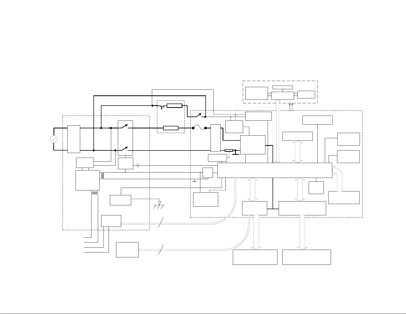
5 WIRING DIAGRAM
5.1 Power Distribution Concept
DD605 Power Distribution concept
Mains
RFI
filter
Rectifier
Auxillary PSU
Chassis PCB
N
P
24V 0V
24V
0V
Comms
Isolation
Isolation
Flood
sensor
relay
Relay
control
2
Heater
Heater
Plate
100
Relay
Fuse
Detector
5 v
reg
0V
24V loads
(Touch switches,
relays, backlights)
Lower (or single)
Controller
Bridge Rectifier
Current
supply
I sens
Gate
0V
LCD
Zero crossing
detector
main PSU
Output Drivers
Buttons
interface
device
Microcomputer
LCD Module
Backlight
Power
Touch switches
Wash Cycle LEDs
Beeper
Wash/drain motor bridge
Salt detector
Tub Home
sensor
sensors
(temperature,current,voltage)
Connections to upper
controller
24V supply
Comms
Fill valve +
Lid Motors
6
dispenser, water softener,
drying fan, LEDs
Wash/drain motor
38

5.2 Wiring Diagram
599464
39
 Loading...