

Page 1

Page 2

Ȧ No part of this manual may be reproduced in any form.
Ȧ All specifications and designs are subject to change without notice.
The export of this product is subject to the authorization of the
government of the country from where the product is exported.
In this manual we have tried as much as possible to describe all the
various matters.
However , we cannot describe all the matters which must not be done,
or which cannot be done, because there are so many possibilities.
Therefore, matters which are not especially described as possible in
this manual should be regarded as ”impossible”.
Page 3

B–64160EN/01
PREFACE
PREFACE
The mode covered by this manual, and their abbreviations are :
Product Name Abbreviations
FANUC Series 0i–PC 0i–PC Series 0i–C 0i
NOTE
Some functions described in this manual may not be applied
to some products.
For details, refer to the DESCRIPTIONS (B–64112EN).
p–1
Page 4

PREFACE
B–64160EN/01
Related manuals of
Series 0i–PC
The following table lists the manuals related to Series 0i–PC.
This manual is indicated by an asterisk(*).
Manual name
FANUC Series 0i–MODEL C/0i Mate–MODEL C
DESCRIPTIONS
FANUC Series 0i–MODEL C/0i Mate–MODEL C
CONNECTION MANUAL (HARDWARE)
FANUC Series 0i–MODEL C/0i Mate–MODEL C
CONNECTION MANUAL (FUNCTION)
FANUC Series 0i–PC
CONNECTION MANUAL (FUNCTION)
FANUC Series 0i–PC OPERATOR’S MANUAL B–64154EN
FANUC Series 0i–MODEL C/0i Mate–MODEL C
MAINTENANCE MANUAL
FANUC Series 0i–PC PARAMETER MANUAL B–64160EN *
PROGRAMMING MANUAL
Macro Compiler/Macro Executor
PROGRAMMING MANUAL
Specification
number
B–64112EN
B–64113EN
B–64113EN–1
B–64153EN
B–64115EN
B–61803E–1
FAPT MACRO COMPILER (For Personal Computer)
PROGRAMMING MANUAL
PMC
PMC Ladder Language PROGRAMMING MANUAL B–61863E
Network
Profibus–DP Board OPERA T OR’S MANUAL B–62924EN
FAST Ethernet Board/FAST DA TA SERVER
OPERA T OR’S MANUAL
Ethernet Board/DA T A SERVER Board
OPERA T OR’S MANUAL
DeviceNet Board OPERA T OR’S MANUAL B–63404EN
Open CNC
FANUC OPEN CNC Basic Operation Package 1
(For Windows95/NT) OPERA TOR’S MANUAL
FANUC OPEN CNC (DNC Operation Management
Package) OPERATOR’S MANUAL
B–66102E
B–63644EN
B–63354EN
B–62994EN
B–63214EN
p–2
Page 5

B–64160EN/01
PREFACE
Related manuals of
SERVO MOTOR ais/
ai series
Related manuals of
Servo Motor β series
The following table lists the manuals related to SERVO MOTOR ais/
ai series.
Manual name
FANUC AC SER VO MOTOR ais series
FANUC AC SER VO MOTOR ai series
DESCRIPTIONS
FANUC AC SER VO MOTOR ais series
FANUC AC SER VO MOTOR ai series
P ARAMETER MANUAL
FANUC AC SPINDLE MOT OR ai series DESCRIPTIONS B–65272EN
FANUC AC SPINDLE MOT OR ai series
P ARAMETER MANUAL
FANUC SER VO AMPLIFIER ai series DESCRIPTIONS B–65282EN
FANUC AC SER VO MOTOR ais series
FANUC AC SER VO MOTOR ai series
FANUC AC SPINDLE MOT OR ai series
FANUC SER VO AMPLIFIER ai series
MAINTENANCE MANUAL
Specification
number
B–65262EN
B–65270EN
B–65280EN
B–65285EN
The following table lists the manuals related to Servo Motor β series.
Manual name
FANUC SER VO MOT OR β series DESCRIPTIONS B–65232EN
Specification
number
FANUC SER VO MOT OR β series
MAINTENANCE MANUAL
FANUC SER VO MOT OR β series(I/O Link Option)
DESCRIPTIONS
B–65235EN
B–65245EN
p–3
Page 6

Page 7

B–64160EN/01
Table of Contents
PREFACE p–1. . . . . . . . . . . . . . . . . . . . . . . . . . . . . . . . . . . . . . . . . . . . . . . . . . . . . . . . . . . . . . . .
1. DISPLAYING PARAMETERS 1. . . . . . . . . . . . . . . . . . . . . . . . . . . . . . . . . . . . . . . . . . . .
2. SETTING PARAMETERS FROM MDI 2. . . . . . . . . . . . . . . . . . . . . . . . . . . . . . . . . . . .
3. INPUTTING AND OUTPUTTING PARAMETERS THROUGH THE
READER/PUNCHER INTERF ACE 4. . . . . . . . . . . . . . . . . . . . . . . . . . . . . . . . . . . . . . .
3.1 OUTPUTTING PARAMETERS THROUGH THE READER/PUNCHER INTERFACE 5. . . . . . . .
3.2 INPUTTING PARAMETERS THROUGH THE READER/PUNCHER INTERFACE 6. . . . . . . . . .
4. DESCRIPTION OF PARAMETERS 7. . . . . . . . . . . . . . . . . . . . . . . . . . . . . . . . . . . . . . .
4.1 PARAMETERS OF SETTING 8. . . . . . . . . . . . . . . . . . . . . . . . . . . . . . . . . . . . . . . . . . . . . . . . . . . . . .
4.2 PARAMETERS OF READER/PUNCHER INTERFACE 11. . . . . . . . . . . . . . . . . . . . . . . . . . . . . . . . .
4.2.1 Parameters Common to all Channels 12. . . . . . . . . . . . . . . . . . . . . . . . . . . . . . . . . . . . . . . . . . . . . . . . . .
4.2.2 Parameters of Channel 1 (I/O CHANNEL=0) 13. . . . . . . . . . . . . . . . . . . . . . . . . . . . . . . . . . . . . . . . . . .
4.2.3 Parameters of Channel 1 (I/O CHANNEL=1) 14. . . . . . . . . . . . . . . . . . . . . . . . . . . . . . . . . . . . . . . . . . .
4.2.4 Parameters of Channel 2 (I/O CHANNEL=2) 15. . . . . . . . . . . . . . . . . . . . . . . . . . . . . . . . . . . . . . . . . . .
4.3 PARAMETERS OF DNC2 INTERFACE 17. . . . . . . . . . . . . . . . . . . . . . . . . . . . . . . . . . . . . . . . . . . . .
4.4 PARAMETERS OF REMOTE DIAGNOSIS 20. . . . . . . . . . . . . . . . . . . . . . . . . . . . . . . . . . . . . . . . . . .
4.5 PARAMETER OF MEMORY CARD INTERFACE 23. . . . . . . . . . . . . . . . . . . . . . . . . . . . . . . . . . . . .
4.6 PARAMETERS OF DATA SERVER 24. . . . . . . . . . . . . . . . . . . . . . . . . . . . . . . . . . . . . . . . . . . . . . . . .
4.7 PARAMETERS OF ETHERNET 26. . . . . . . . . . . . . . . . . . . . . . . . . . . . . . . . . . . . . . . . . . . . . . . . . . . .
4.8 PARAMETERS OF POWER MATE CNC MANAGER 27. . . . . . . . . . . . . . . . . . . . . . . . . . . . . . . . . .
4.9 PARAMETERS OF AXIS CONTROL/INCREMENT SYSTEM 28. . . . . . . . . . . . . . . . . . . . . . . . . . .
4.10 PARAMETERS OF COORDINATES 36. . . . . . . . . . . . . . . . . . . . . . . . . . . . . . . . . . . . . . . . . . . . . . . .
4.11 PARAMETERS OF STROKE CHECK 40. . . . . . . . . . . . . . . . . . . . . . . . . . . . . . . . . . . . . . . . . . . . . . .
4.12 PARAMETERS OF FEEDRATE 44. . . . . . . . . . . . . . . . . . . . . . . . . . . . . . . . . . . . . . . . . . . . . . . . . . . .
4.13 PARAMETERS OF ACCELERATION/DECELERATION CONTROL 49. . . . . . . . . . . . . . . . . . . . .
4.14 PARAMETERS OF SERVO 62. . . . . . . . . . . . . . . . . . . . . . . . . . . . . . . . . . . . . . . . . . . . . . . . . . . . . . . .
4.15 PARAMETERS OF DI/DO 83. . . . . . . . . . . . . . . . . . . . . . . . . . . . . . . . . . . . . . . . . . . . . . . . . . . . . . . . .
4.16 PARAMETERS OF DISPLAY AND EDIT 86. . . . . . . . . . . . . . . . . . . . . . . . . . . . . . . . . . . . . . . . . . . .
4.17 PARAMETERS OF PROGRAMS 105. . . . . . . . . . . . . . . . . . . . . . . . . . . . . . . . . . . . . . . . . . . . . . . . . . .
4.18 PARAMETERS OF PITCH ERROR COMPENSATION 110. . . . . . . . . . . . . . . . . . . . . . . . . . . . . . . . .
4.19 PARAMETERS OF TOOL COMPENSATION 117. . . . . . . . . . . . . . . . . . . . . . . . . . . . . . . . . . . . . . . . .
4.20 PARAMETERS OF SCALING/COORDINATE ROTATION 120. . . . . . . . . . . . . . . . . . . . . . . . . . . . . .
4.21 PARAMETERS OF NORMAL DIRECTION CONTROL 122. . . . . . . . . . . . . . . . . . . . . . . . . . . . . . . .
4.22 PARAMETERS OF CUSTOM MACROS 126. . . . . . . . . . . . . . . . . . . . . . . . . . . . . . . . . . . . . . . . . . . . .
4.23 PARAMETERS OF SKIP FUNCTION 131. . . . . . . . . . . . . . . . . . . . . . . . . . . . . . . . . . . . . . . . . . . . . . .
4.24 PARAMETERS OF EXTERNAL DATA INPUT/OUTPUT 133. . . . . . . . . . . . . . . . . . . . . . . . . . . . . . .
4.25 PARAMETERS OF GRAPHIC DISPLAY 134. . . . . . . . . . . . . . . . . . . . . . . . . . . . . . . . . . . . . . . . . . . . .
4.26 PARAMETERS OF DISPLAYING OPERATION TIME AND NUMBER OF PARTS 136. . . . . . . . . .
4.27 PARAMETERS OF POSITION SWITCH FUNCTIONS 140. . . . . . . . . . . . . . . . . . . . . . . . . . . . . . . . .
4.28 PARAMETERS OF MANUAL HANDLE FEED AND HANDLE INTERRUPTION 144. . . . . . . . . . .
4.29 PARAMETERS OF SOFTWARE OPERATOR’S PANEL 147. . . . . . . . . . . . . . . . . . . . . . . . . . . . . . . .
c–1
Page 8

4.30 PARAMETERS OF AXIS CONTROL BY PMC 150. . . . . . . . . . . . . . . . . . . . . . . . . . . . . . . . . . . . . . .
4.31 PARAMETERS OF SIMPLE SYNCHRONOUS CONTROL 155. . . . . . . . . . . . . . . . . . . . . . . . . . . . . .
4.32 PARAMETERS OF SEQUENCE NUMBER COMPARISON AND STOP 162. . . . . . . . . . . . . . . . . . .
4.33 PARAMETERS OF FS0i BASIC FUNCTIONS 163. . . . . . . . . . . . . . . . . . . . . . . . . . . . . . . . . . . . . . . .
4.34 OTHER PARAMETERS 165. . . . . . . . . . . . . . . . . . . . . . . . . . . . . . . . . . . . . . . . . . . . . . . . . . . . . . . . . .
4.35 PARAMETERS OF MAINTENANCE 169. . . . . . . . . . . . . . . . . . . . . . . . . . . . . . . . . . . . . . . . . . . . . . .
4.36 PARAMETERS OF OPERATION HISTORY 170. . . . . . . . . . . . . . . . . . . . . . . . . . . . . . . . . . . . . . . . . .
4.37 PARAMETERS OF THE PRESS FUNCTION 174. . . . . . . . . . . . . . . . . . . . . . . . . . . . . . . . . . . . . . . . .
4.38 PARAMETERS FOR THE SPEED AND LOOP GAIN SWITCH 185. . . . . . . . . . . . . . . . . . . . . . . . . .
4.39 PARAMETERS FOR THE NIBBLING FUNCTION 195. . . . . . . . . . . . . . . . . . . . . . . . . . . . . . . . . . . .
4.40 PARAMETERS FOR THE PATTERN FUNCTION 198. . . . . . . . . . . . . . . . . . . . . . . . . . . . . . . . . . . . .
4.41 PARAMETERS FOR THE TURRET AXIS 203. . . . . . . . . . . . . . . . . . . . . . . . . . . . . . . . . . . . . . . . . . .
4.42 PARAMETERS FOR C–AXIS CONTROL 207. . . . . . . . . . . . . . . . . . . . . . . . . . . . . . . . . . . . . . . . . . . .
4.43 PARAMETERS FOR THE SAFETY ZONE 213. . . . . . . . . . . . . . . . . . . . . . . . . . . . . . . . . . . . . . . . . . .
4.44 ADDITIONAL PARAMETERS FOR DI/DO SIGNALS 219. . . . . . . . . . . . . . . . . . . . . . . . . . . . . . . . .
APPENDIX
Table of Contents
B–64160EN/01
A. CHARACTER CODE LIST 223. . . . . . . . . . . . . . . . . . . . . . . . . . . . . . . . . . . . . . . . . . . . . .
c–2
Page 9
B–64160EN/01
1
DISPLAYING PARAMETERS
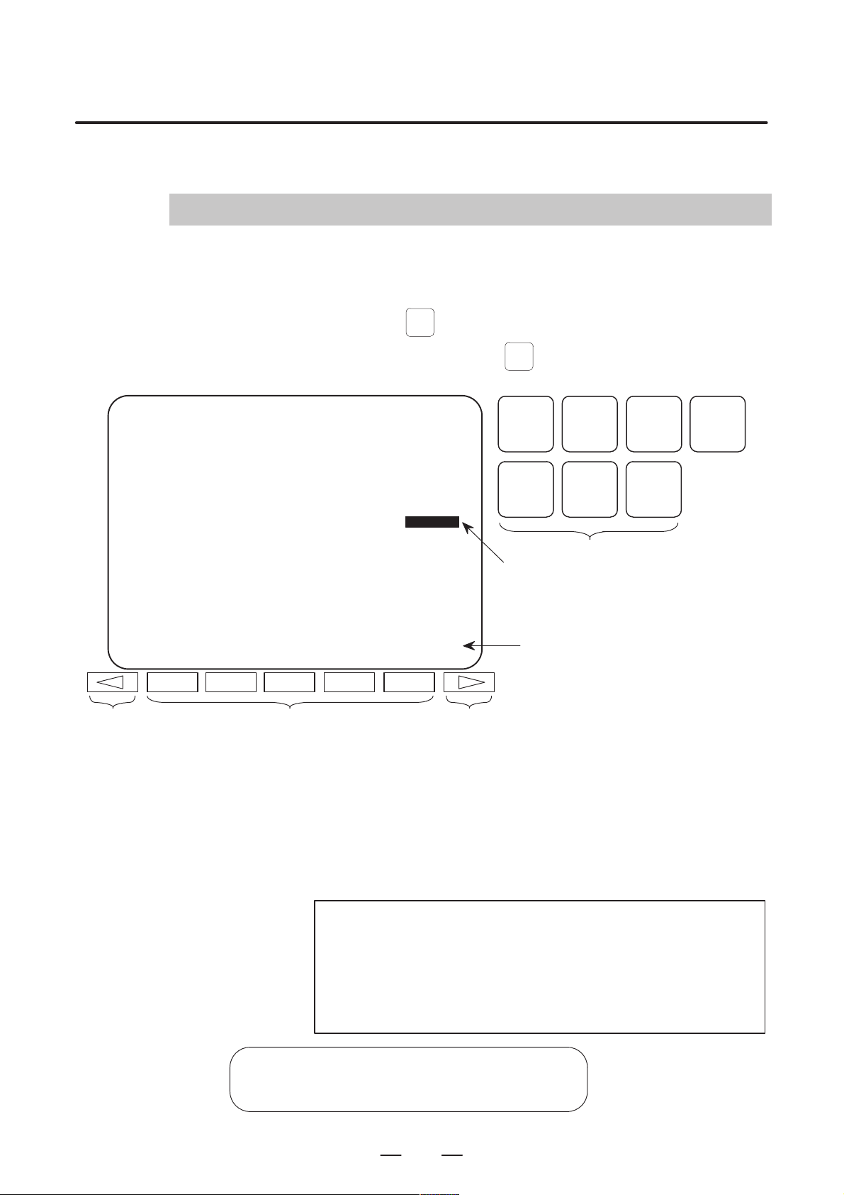
Follow the procedure below to display parameters.
(1) Press the
SYSTEM
1. DISPLAYING PARAMETERS
function key on the MDI as many times as required,
or alternatively , press the
SYSTEM
section display soft key. The parameter screen is then selected.
PARAMETER (FEEDRATE) O0001 N12345
1401 RDR JZR RF0 LRP RPD
0 0 0 0 0 0 0 0
1402 DLF HFC
0 0 0 0 0 0 0 0
1410 DRY RUN FEEDRATE 10000
1411 INIT.CUTTING F 0
1420 RAPID FEEDRATE X 15000
Y 15000
Z 15000
>
MEM STRT MTN FIN *** 10:02:35
[PARAM] [DGNOS] [ PMC ] [SYSTEM] [(OPRT)]
Return menu key Soft key Continuous menu key
POS PROG
SYSTEM MESSAGE GRAPH
Cursor
(2) The parameter screen consists of multiple pages. Use step (a) or (b)
to display the page that contains the parameter you want to display.
(a) Use the page select key or the cursor move keys to display the de-
sired page.
(b) Enter the data number of the parameter you want to display from
the keyboard, then press the [NO.SRH] soft key. The parameter
page containing the specified data number appears with the cursor positioned at the data number. (The data is displayed in reverse video.)
function key once, then the PARAM
OFFSET
SETTING
Function key
Soft key display
(section select)
CUSTOM
NOTE
If key entry is started with the section select soft keys
displayed, they are replaced automatically by operation
select soft keys including [NO.SRH]. Pressing the [(OPRT)]
soft key can also cause the operation select keys to be
displayed.
>
MEM STRT MTN FIN *** 10:02:34
[NO.SRH] [ ON:1 ] [ OFF:0 ] [+INPUT] [INPUT ]
1
Data entered from
←
the keyboard
Soft key display
←
(section select)
Page 10

2. SETTING PARAMETERS FROM MDI
SETTING P ARAMETERS FROM MDI
2
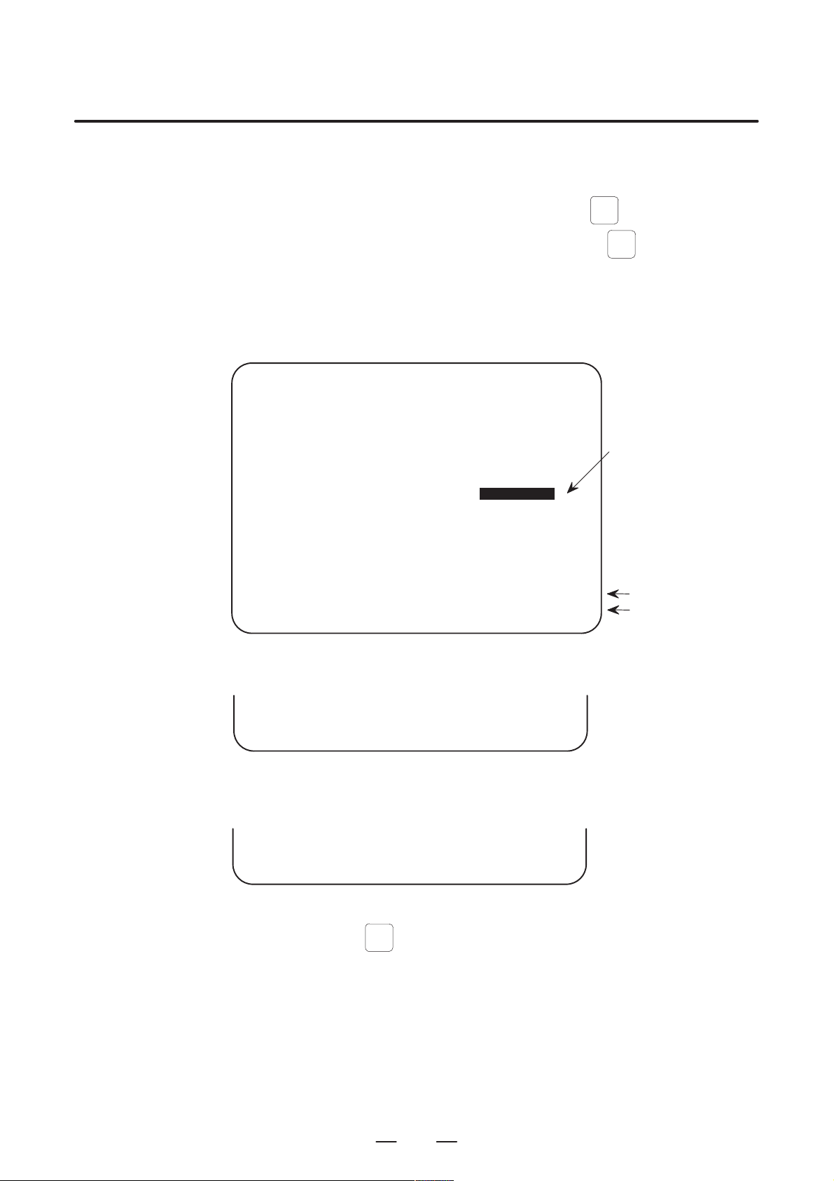
Follow the procedure below to set parameters.
(1) Place the NC in the MDI mode or the emergency stop state.
(2) Follow the substeps below to enable writing of parameters.
1. To display the setting screen, press the
B–64160EN/01
OFFSET
function key as
SETTING
many times as required, or alternatively press the
key once, then the [SETTING] section select soft key. The first
page of the setting screen appears.
2. Position the cursor on “P ARAMETER WRITE” using the cursor
move keys.
SETTING (HANDY) O0001 N00010
PARAMETER WRITE = (0:DISABLE 1:ENABLE)
TV CHECK = 0 (0:OFF 1:ON)
PUNCH CODE = 0 (0:EIA 1:ISO)
INPUT UNIT = 0 (0:MM 1:INCH)
I/O CHANNEL = 0 (0–3:CHANNEL NO.)
0
3. Press the [(OPRT)] soft key to display operation select soft keys.
>
MDI STOP *** *** *** 10:03:02
[NO.SRH] [ ON:1 ] [ OFF:0 ] [+INPUT] [INPUT]
4. To set “PARAMETER WRITE=” to 1, press the ON:1 soft key,
or alternatively enter 1 and press the INPUT soft key . From now
on, the parameters can be set. At the same time an alarm condition (P/S100 PARAMETER WRITE ENABLE) occurs in the
CNC.
OFFSET
function
SETTING
← Soft key display
(section select)
SYSTEM
(3 ) To display the parameter screen, press the
times as required, or alternatively press the
function key as many
SYSTEM
function key once,
then the PARAM section select soft key.
(See “1. Displaying Parameters.”)
(4) Display the page containing the parameter you want to set, and position
the cursor on the parameter. (See “1. Displaying Parameters.”)
(5 ) Enter data, then press the [INPUT] soft key. The parameter indicated
by the cursor is set to the entered data.
2
Page 11

B–64160EN/01
2. SETTING PARAMETERS FROM MDI
[Example] 12000 [INPUT]
PARAMETER (FEEDRATE) O0001 N00010
1401 RDR JZR RPD
00000000
1402 JRV
00000000
1410 DRY RUN FEEDRATE
1412 0
1420 RAPID FEEDRATEX 15000
Y 15000
Z 15000
>
MDI STOP *** *** ALM 10:03:10
[NO.SRH] [ ON:1 ] [ OFF:0 ] [+INPUT] [INPUT]
12000
Cursor
Data can be entered continuously for parameters, starting at the selected
parameter, by separating each data item with a semicolon (;).
[Example] Entering 10;20;30;40 and pressing the INPUT key assigns values 10, 20,
30, and 40 to parameters in order starting at the parameter indicatedby the
cursor.
(6) Repeat steps (4) and (5) as required.
(7) If parameter setting is complete, set “PARAMETER WRITE=” to 0
on the setting screen to disable further parameter setting.
(8) Reset the NC to release the alarm condition (P/S100).
If an alarm condition (P/S000 PLEASE TURN OFF POWER) occurs
in the NC, turn it off before continuing operation.
3
Page 12

3. INPUTTING AND OUTPUTTING PARAMETERS THROUGH
THE READER/PUNCHER INTERFACE
INPUTTING AND OUTPUTTING PARAMETERS THROUGH THE READER/PUNCHER INTERF ACE
3
This section explains the parameter input/output procedures for
input/output devices connected to the reader/puncher interface.
The following description assumes the input/output devices are ready for
input/output. It also assumes parameters peculiar to the input/output
devices, such as the baud rate and the number of stop bits, have been set
in advance. (See Section 4.2)
B–64160EN/01
4
Page 13
B–64160EN/01
3. INPUTTING AND OUTPUTTING PARAMETERS THROUGH
THE READER/PUNCHER INTERFACE
3.1
OUTPUTTING PARAMETERS THROUGH THE READER/PUNCHER INTERFACE
PARAMETER (FEEDRATE) O0001 N00010
1401 RDR JZR RPD
1402 JRV
1410 DRY RUN FEEDRATE
1412 0
1420 RAPID FEEDRATEX 15000
(1) Select the EDIT mode or set to Emergency stop.
SYSTEM
(2 ) To select the parameter screen, press the
times as required, or alternatively press the
function key as many
SYSTEM
function key once,
then the [PARAM] section select soft key.
(3 ) Press the [(OPRT)] soft key to display operation select soft keys, then
press the forward menu key located at the right–hand side of the soft
keys to display another set of operation select keys including
[PUNCH].
00000000
00000000
12000
Y 15000
Z 15000
Cursor
>
MDI STOP *** *** ALM 10:03:10
[NO.SRH] [ON:1] [OFF:0] [+INPUT] [INPUT]
(4) Pressing the [PUNCH] soft key changes the soft key display as
shown below:
>
EDIT STOP *** *** *** 10:35:03
[ ] [ ] [ ] [CANCEL] [ EXEC ]
(5) Press the [EXEC] soft key to start parameter output. When
parameters are being output, “OUTPUT” blinks in the state display
field on the lower part of the screen.
>
EDIT STOP *** *** *** 10:35:04 OUTPUT
[ ] [ ] [ ] [CANCEL] [ EXEC ]
(6 ) When parameter output terminates, “OUTPUT” stops blinking. Press
RESET
the
key to interrupt parameter output.
State display
Soft key display
(operation select)
← OUTPUT blinking
5
Page 14

3. INPUTTING AND OUTPUTTING PARAMETERS THROUGH
THE READER/PUNCHER INTERFACE
B–64160EN/01
3.2
INPUTTING PARAMETERS THROUGH THE READER/PUNCHER INTERFACE
(1) Place the NC in the emergency stop state.
(2) Enable parameter writing.
OFFSET
1. To display the setting screen, press the
many times as required, or alternatively press the
function key as
SETTING
OFFSET
SETTING
function
key once, then the [SETING] section select soft key. The first
page of the setting screen appears.
2. Position the cursor on “P ARAMETER WRITE” using the cursor
move keys.
3. Press the [(OPRT)] soft key to display operation select soft keys.
4. To set “PARAMETER WRITE=” to 1, press the ON:1 soft key,
or alternatively enter 1, then press the [INPUT] soft key. From
now on, parameters can be set. At the same time an alarm condition (P/S100 PARAMETER WRITE ENABLE) occurs in the
NC.
(3 ) To select the parameter screen, press the
times as required, or alternatively press the
SYSTEM
function key as many
SYSTEM
key once, then
[PARAM] soft key.
(4) Press the [(OPRT)] soft key to display operation select keys, then
press the forward menu key located at the right–hand side of the soft
keys to display another set of operation select soft keys including
[READ].
>
EDIT STOP ALM 10:37:30
[ ] [ READ ] [PUNCH] [ ] [ ]
–EMG– ALM
(5) Pressing the [READ] soft key changes the soft key display as shown
below:
>
EDIT STOP ALM 10:37:30
[ ] [ ] [ ] [CANCEL] [ EXEC ]
–EMG– ALM
(6) Press the [EXEC] soft key to start inputting parameters from the
input/output device. When parameters are being input, “INPUT”
blinks in the state display field on the lower part of the screen.
>
EDIT STOP ALM 10:37:30 INPUT
[ ] [ ] [ ] [CANCEL] [ EXEC ]
–EMG– ALM
(7 ) When parameter input terminates, “INPUT” stops blinking. Press the
RESET
key to interrupt parameter input.
(8) When parameter read terminates, “INPUT” stops blinking, and an
alarm condition (P/S000) occurs in the NC. Turn it off before
continuing operation.
← State display
← Soft key display
← INPUT blinking
6
Page 15

B–64160EN/01
0 or 1
–128 to 127
In some parameters, signs are
–128 to 127
In some parameters, signs are
–32768 to 32767
In some parameters, signs are
–32768 to 32767
In some parameters, signs are
–99999999 to 99999999
4
DESCRIPTION OF PARAMETERS
Parameters are classified by data type as follows:
Table 4 Data Types and Valid Data Ranges of Parameters
Data type Valid data range Remarks
Bit
Bit axis
Byte
Byte axis
Word
Word axis
2–word
2–word axis
0 to 255
0 to 65535
4. DESCRIPTION OF PARAMETERS
ignored.
ignored.
[Example]
0000
Data No.
1023 Servo axis number of a specific axis
Data No.
NOTE
1 For the bit type and bit axis type parameters, a single data
number is assigned to 8 bits. Each bit has a different
meaning.
2 The axis type allows data to be set separately for each
control axis.
3 The valid data range for each data type indicates a general
range. The range varies according to the parameters. For
the valid data range of a specific parameter, see the
explanation of the parameter.
(1) Notation of bit type and bit axis type parameters
#7
#6 #5
SEQ
#4 #3 #2
Data #0 to #7 are bit positions.
INI
#1
ISO
(2) Notation of parameters other than bit type and bit axis type
Data.
#0
TVC
NOTE
The bits left blank in 4. DESCRIPTION OF PARAMETERS
and parameter numbers that appear on the display but are
not found in the parameter list are reserved for future
expansion. They must always be 0.
7
Page 16

4. DESCRIPTION OF PARAMETERS
B–64160EN/01
4.1
P ARAMETERS OF SETTING
[Data type] Bit
#7
0000
#6 #5
SEQ
#4 #3 #2
The following parameter can be set at “Setting screen”.
TVC TV check
0 : Not performed
1 : Performed
ISO Code used for data output
0 : EIA code
1 : ISO code
INI Unit of input
0 : In mm
1 : In inches
SEQ Automatic insertion of sequence numbers
0: Not performed
1: Performed
When a program is prepared by using MDI keys in the part program
storage and edit mode, a sequence number can automatically be assigned
to each block in set increments. Set the increment to parameter 3216.
INI
#1
ISO
#0
TVC
SJZ0002
The following parameters can be set at “Setting screen”.
[Data type] Bit
RDG Remote diagnosis is
0: Not performed.
1: Performed.
To use an RS–232C serial port for performing remote diagnosis, connect
and setup the modem, cable, and the like, then set 1 in this parameter.
SJZ Manual reference position si performed as follows:
0 : When no reference position has been set, reference position return is
performed using deceleration dogs. When a reference position is
already set, reference position return is performed using rapid traverse
and deceleration dogs are ignored.
1 : Reference position return is performed using deceleration dogs at all
times.
Note
SJZ is enabled when bit 3 (HJZ) of parameter No.1005 is
set to 1. When a reference position is set without a dog,
(i.e. when bit 1 (DLZ) of parameter No.1002 is set to 1 or
bit 1 (DLZx) of parameter No.1005 is set to 1) reference
position return after reference position setting is
performed using rapid traverse at all times, regardless of
the setting of SJZ.
#7
#6 #5 #4 #3 #2 #1 #0
RDG
8
Page 17

B–64160EN/01
4. DESCRIPTION OF PARAMETERS
0012
The following parameters can be set at “Setting screen”.
[Data type] Bit axis
MIRx Mirror image for each axis
0 : Mirror image is off.
1 : Mirror image is on.
0020
This parameter can be set at “Setting screen”.
[Data type] Byte
[Valid data range] 0 to 35
I/O CHANNEL: Selection of the input/output device to be used
The CNC provides the following interfaces for data transfer to and from
the host computer and external input/output devices:
D Input/output device interface (RS–232C serial port 1, 2)
D DNC2 interface
Data can be transferred to and from a personal computer connected via the
FOCAS1/Ethernet or FOCAS1/HSSB.
In addition, data can be transferred to and from the Power Mate via the
FANUC I/O Link.
This parameter selects the interface used to transfer data to and from an
input/output device.
#7
I/O CHANNEL: Selection of an input/output device or selection of input device in
the foreground
#6 #5 #4 #3 #2 #1 #0
MIRx
Setting Description
0, 1 RS–232C serial port 1
2 RS–232C serial port 2
4 Memory card interface
5 Data server interface
6 The DNC operation is performed or M198 is specified by FOCAS1/
Ethernet.
10 DNC2 interface
15 M198 is specified by FOCAS1/HSSB. (Bit 1 (NWD) of parameter
20
21
22
34
35
No. 8706) must also be specified.)
Group 0
|
Group 1
Group 2
|
Group 14
Group 15
Data is transferred between the CNC and a Power
Mate in group n (n: 0 to 15) via the FANUC I/O Link.
Supplemental remark 1
If the DNC operation is performed with FOCAS1/HSSB, the setting
of parameter No. 20 does not matter. The DMMC signal <G042.7>
is used.
Supplemental remark 2
If bit 0 (IO4) of parameter No. 110 is set to control the I/O channels
separately , the I/O channels can be divided into four types: input and
output in the foreground and input and output in the background. If
so, parameter No. 20 becomes a parameter for selecting the input
device in the foreground.
9
Page 18
4. DESCRIPTION OF PARAMETERS
B–64160EN/01
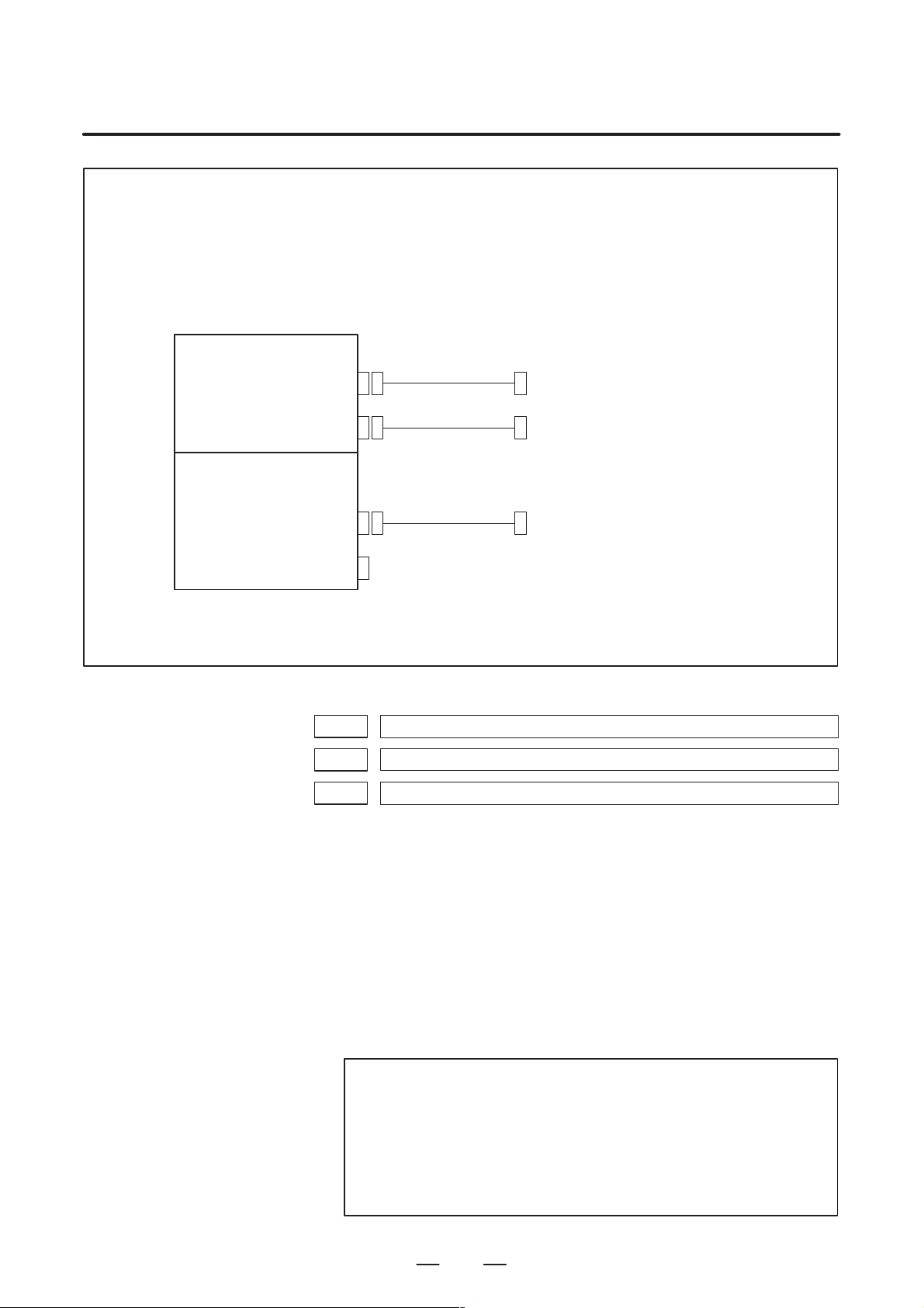
NOTE
1 An input/output device can also be selected using the setting screen. Usually, the setting screen
is used.
2 The specifications (such as the baud rate and the number of stop bits) of the input/output
devices to be connected must be set in the corresponding parameters for each interface
beforehand. (See Section 4.2.) I/O CHANNEL = 0 and I/O CHANNEL = 1 represent input/output
devices connected to RS–232C serial port 1. Separate parameters for the baud rate, stop bits,
and other specifications are provided for each channel.
Mother board
RS–232–C serial port 1
R232–1(JD36A)
RS–232–C serial port 2
R232–2(JD36B)
Serial communication board
DNC2 board
I/O CHANNEL=0, 1
(Channel 1)
I/O CHANNEL=2
(Channel 2)
RS-232-C I/O device
RS-232-C I/O device
R232-3(JD28A)
R422-1(JD6A)
I/O CHANNEL=3
(Channel 3)
RS-232-C I/O device
(when a remote buffer or DNC2 board is used)
3 The input/output unit interface may be referred to as the reader/punch interface.
RS–232C serial port 1 and RS–232C serial port 2 are also referred to as channel 1 and channel
2, respectively.
0021 Setting of the output device in the foreground
0022 Setting of the input device in the background
0023 Setting of the output device in the background
These parameters can be set at “Setting screen”.
[Data type] Byte
[Valid data range] 0 to 2, 5, 10
These parameters are valid only when bit 0 (IO4) of parameter No. 110 is
set to control the I/O channels separately.
The parameters set individual input/output devices if the I/O channels are
divided into these four types: input and output in the foreground and input
and output in the background. The input device in the foreground is set in
parameter No. 20. For the details of the settings, see the table provided
with the description of parameter No. 20.
NOTE
If different input/output devices are simultaneously used in
the foreground and background, just a value from 0 to 2 can
be specified for the background device.
If an attempt is made to use a busy input/output device, an
alarm (P/S233 or BP/S233) will be raised. Note that the
settings 0 and 1 indicate the same input/output device.
10
Page 19

B–64160EN/01
4. DESCRIPTION OF PARAMETERS
4.2
PARAMETERS OF READER/PUNCHER INTERFACE
0020
Specify a channel for an input/output device.
I/ O CHANNEL
=0 : Channel1
=1 : Channel1
=2 : Channel2
I/O CHANNEL
This CNC has two channels CRS–232–C serial port1 and RS–232–C
serial port2 of input/output device interfaces. The input/output device to
be used is specified by setting the channel connected to that device in
setting parameter I/O CHANNEL.
The specified data, such as a baud rate and the number of stop bits, of an
input/output device connected to a specific channel must be set in
parameters for that channel in advance.
For channel 1, two combinations of parameters to specify the input/output
device data are provided.
The following shows the interrelation between the input/output device
interface parameters for the channels.
Input/output channel number (parameter No.0020)
↓
Stop bit and other data
Number specified for the input/
output device
Baud rate
Stop bit and other data
Number specified for the input/
output device
Baud rate
I/O CHANNEL=0
(channel 1)
I/O CHANNEL=1
(channel 1)
0101
0102
0103
0111
0112
0113
0121
I/O CHANNEL=2
(channel 2)
Fig.4.2 I/O Device Interface Settings
0122
0123
Stop bit and other data
Number specified for the input/
output device
Baud rate
11
Page 20

4. DESCRIPTION OF PARAMETERS
4.2.1
Parameters Common to all Channels
[Data type] Byte
0024 Port for communication with the PMC ladder development tool (FAPT LADDER–II/III)
B–64160EN/01
This parameter can be set at “Setting screen”.
This parameter sets the port to be used for communication with the PMC
ladder development tool (FAPT LADDER–II/III).
0 : HSSB (COP7)
1 : RS–232C serial port 1 (JD36A)
2 : RS–232C serial port 2 (JD36B)
#7
ENS0100
#6
IOP
#5
ND3
#4 #3
NCR#2CRF
#1
CTV
[Data type] Bit
CTV: Character counting for TV check in the comment section of a program.
0 : Performed
1 : Not performed
CRF EOB (end of block) to be output in the ISO code:
0: Depends on the setting of bit 3 (NCR) of parameter No. 100.
1: is “CR”“LF”.
Note) The EOB output patterns are as shown below:
NCR CRF EOB output format
0 0 “LF” “CR” “CR”
0 1 “CR” “LF”
1 0 “LF”
1 1 “CR” “LF”
NCR Output of the end of block (EOB) in ISO code
0 : LF, CR, CR are output.
1 : Only LF is output.
ND3 In DNC operation, a program is:
0 : Read block by block. (A DC3 code is output for each block.)
1 : Read continuously until the buffer becomes full. (A DC3 code is
output when the buffer becomes full.)
#0
NOTE
In general, reading is performed more efficiently when ND3
set to 1. This specification reduces the number of buffering
interruptions caused by reading of a series of blocks
specifying short movements. This in turn reduces the
effective cycle time.
IOP Specifies how to stop program input/output operations.
0 : An NC reset can stop program input/output operations.
1 : Only the [STOP] soft key can stop program input/output operations.
(An reset cannot stop program input/output operations.)
12
Page 21

B–64160EN/01
4. DESCRIPTION OF PARAMETERS
ENS Action taken when a NULL code is found during read of EIA code
0 : An alarm is generated.
1 : The NULL code is ignored.
4.2.2
Parameters of Channel 1 (I/O CHANNEL=0)
0110
[Data type] Bit
IO4 Separate control of I/O channel numbers is:
0: Not performed.
1: Performed.
If the I/O channels are not separately controlled, set the input/output
device in parameter No. 20.
If the I/O channels are separately controlled, set the input device and
output device in the foreground and the input device and output device in
the background in parameters No. 20 to No. 23 respectively.
Separate control of I/O channels makes it possible to perform background
editing, program input/output, and the like during the DNC operation.
[Data type] Bit type
#7
#7
NFD0101
#6 #5 #4 #3 #2 #1 #0
IO4
#6 #5 #4 #3
ASI
#2 #1
HAD
#0
SB2
SB2 The number of stop bits
0 : 1
1 : 2
HAD An alarm raised for the internal handy file is:
0: Not displayed in detail on the NC screen. (PS alarm 86 is displayed.)
1: Displayed in detail on the NC screen.
ASI Code used at data input
0 : EIA or ISO code (automatically distinguished)
1 : ASCII code
NFD Feed before and after the data at data output
0 : Output
1 : Not output
NOTE
When input/output devices other than the FANUC PPR
are used, set NFD to 1.
0102 Number specified for the input/ou tpu t device (when the I/O CHANNEL is set to 0)
[Data type] Byte
Set the number specified for the input/output device used when the I/O
CHANNEL is set to 0, with one of the set values listed in Table 4.2 (a).
13
Page 22

4. DESCRIPTION OF PARAMETERS
0103 Baud rate (when the I/O CHANNEL is set to 0)
[Data type] Byte
B–64160EN/01
Table 4.2.2 (a) Set value and Input/Output Device
Set value Input/output device
0 RS–232–C (Used control codes DC1 to DC4)
1 FANUC CASSETTE ADAPTOR 1 (FANUC CASSETTE B1/ B2)
2 FANUC CASSETTE ADAPTOR 3 (FANUC CASSETTE F1)
3 FANUC PROGRAM FILE Mate, FANUC FA Card Adaptor
4 RS–232–C (Not used control codes DC1 to DC4)
5 Portable tape reader
6 FANUC PPR
FANUC FLOPPY CASSETTE ADAPT OR, FANUC Handy File
FANUC SYSTEM P-MODEL H
FANUC SYSTEM P-MODEL G, FANUC SYSTEM P-MODEL H
Set baud rate of the input/output device used when the I/O CHANNEL is
set to 0, with a set value in Table 4.2 (b).
Table 4.2.2 (b)
Set value Baud rate (bps)
1
2
3
4
5
6
50
100
110
150
200
300
Set value Baud rate (bps)
7
8
9
10
11
12
600
1200
2400
4800
9600
19200
4.2.3
Parameters of Channel 1 (I/O CHANNEL=1)
[Data type] Bit
These parameters are used when I/O CHANNEL is set to 1. The meanings
of the bits are the same as for parameter 0101.
0112 Number specified for the input/output device (when I/O CHANNEL is set to 1)
[Data type] Byte
Set the number specified for the input/output device used when the I/O
CHANNEL is set to 1, with one of the set values listed in Table 4.2 (a).
0113 Baud rate (when I/O CHNNEL is set to 1)
[Data type] Byte
Set the baud rate of the input/output device used when I/O CHANNEL is
set to 1, with a value in Table 4.2 (b).
#7
NFD0111
#6 #5 #4 #3
ASI
#2 #1 #0
SB2
14
Page 23

B–64160EN/01
4.2.4
Parameters of Channel 2 (I/O CHANNEL=2)
[Data type] Bit
These parameters are used when I/O CHANNEL is set to 2. The meanings
of the bits are the same as for parameter 0101.
0122 Number specified for the input/output device (when I/O CHANNEL is set to 2)
[Data type] Byte
Set the number specified for the input/output device used when I/O
CHANNEL is set to 2, with a value in Table 4.2 (a).
0123 Baud rate (when the I/O CHANNEL is set to 2)
[Data type] Byte
Set the baud rate of the input/output device used when I/O CHANNEL is
set to 2, with a value in Table 4.2 (b).
4. DESCRIPTION OF PARAMETERS
#7
NFD0121
#6 #5 #4 #3
ASI
#2 #1 #0
SB2
#7
0134
#6 #5 #4
NCD
#3 #2
NOTE
When this parameter is set, the power must be turned off
before operation is continued.
[Data type] Bit
PRY Parity bit
0: Not used
1: Used
SYN Reset/alarm in protocol B
0: Not reported to the host
1: Reported to the host with SYN and NAK codes
NCD CD (signal quality detection) of the RS–232C interface
0: Checked
1: Not checked
SYN
#1
PRY
#0
15
Page 24

4. DESCRIPTION OF PARAMETERS
B–64160EN/01
#7
RMS0135
#6 #5 #4 #3 #2
NOTE
When this parameter is set, the power must be turned off
before operation is continued.
[Data type] Bit
ASC Communication code except NC data
0: ISO code
1: ASCII code
ETX End code for protocol A or extended protocol A
0: CR code in ASCII/ISO
1: ETX code in ASCII/ISO
NOTE
Use of ASCII/ISO is specified by ASC.
PRA Communication protocol
0: Protocol B
1: Protocol A
RMS State of remote/tape operation when protocol A is used
0: Always 0 is returned.
1: Contents of the change request of the remote/tape operation in the
SET command from the host is returned.
PRA
#1
ETX
#0
ASC
#7
MDN0138
#6 #5 #4 #3 #2 #1 #0
[Data type] Bit
MDN The DNC operation function by a memory card is:
0: Disabled.
1: Enabled. (A PCMCIA card attachment is required.)
NOTE
Use a PCMCIA card attachment suited to the CNC to secure
the memory card in the CNC.
16
Page 25

B–64160EN/01
4.3
P ARAMETERS OF DNC2 INTERF ACE
[Data type] Bit
4. DESCRIPTION OF PARAMETERS
#7
0140
#6 #5 #4 #3
ECD#2NCE
#1 #0
BCC
NOTE
When this parameter is set, the power must be turned off
before operation is continued.
BCC The BCC value (block check characters) for the DNC2 interface is:
0: Checked.
1: Not checked.
Even if the BCC value is not checked, the BCC value itself must be
specified.
NCE The ER (RS–232C) and TR (RS422) signals are:
0: Checked.
1: Not checked.
This parameter is provided only for the DNC2 interface.
ECD Error code of negative acknowledgment
0: A four–digit hexadecimal error code is added to a negative
acknowledgment.
1: No error code is added to a negative acknowledgment.
This parameter is provided only for the DNC2 interface.
NOTE
To use FANUC DNC2 communications library for the host
computer, set this parameter to 1.
0143 Time limit specified for the timer monitoring a response (DNC2 interface)
NOTE
When this parameter is set, the power must be turned off
before operation is continued.
[Data type] Byte
[Unit of data] S
[Valid data range] 1 to 60 (The standard setting is 3.)
0144 Time limit specified for the timer monitoring the EOT signal (DNC2 interface)
NOTE
When this parameter is set, the power must be turned off
before operation is continued.
[Data type] Byte
[Unit of data] S
[Valid data range] 1 to 60 (The standard setting is 5.)
17
Page 26

4. DESCRIPTION OF PARAMETERS
0145 Time required for switching RECV and SEND (DNC2 interface)
[Data type] Byte
[Unit of data] S
[Valid data range] 1 to 60 (The standard setting is 1.)
0146 Number of times the system retries holding communication (DNC2 interface)
[Data type] Byte
B–64160EN/01
NOTE
When this parameter is set, the power must be turned off
before operation is continued.
NOTE
When this parameter is set, the power must be turned off
before operation is continued.
[Unit of data] S
[Valid data range] 1 to 10 (The standard setting is 3.)
Set the maximum number of times the system retries holding
communication with the remote device if the remote device uses an
invalid protocol in the data–link layer or the remote device does not
respond to the request.
0147
Number of times the system sends the message in response to the NAK signal
(DNC2 interface)
NOTE
When this parameter is set, the power must be turned off
before operation is continued.
[Data type] Byte
[Unit of data] Number of times
[Valid data range] 1 to 10 (The standard setting is 2.)
Set the maximum number of times the system retries sending the message
in response to the NAK signal.
0148 Number of characters in overrun (DNC2) interface)
NOTE
When this parameter is set, the power must be turned off
before operation is continued.
[Data type] Byte
[Valid data range] 10 to 225 (The standard setting is 10.)
Set the number of characters the system can receive after transmission is
stopped (CS off).
18
Page 27

B–64160EN/01
4. DESCRIPTION OF PARAMETERS
0149
Number of characters in the data section of the communication packet (DNC2
interface)
NOTE
When this parameter is set, the power must be turned off
before operation is continued.
[Data type] Word
[Valid range] 80 to 256 (The standard setting is 256.)
The standard setting is 256. If the specified value is out of range, a value of
80 or 256 is used.
This parameter determines the maximum length of the packet used in
transmission over the DNC2 interface. Including the two characters at the
start of the packet, the four characters used for a command, and the three
characters at the end, the maximum number of characters in the packet is
nine plus the number specified in parameter No.0149.
Length of the packet
DLE STX
2 bytes 4 bytes 80 to 256 bytes 3 bytes
Command Data section DEL ETX BCC
19
Page 28

4. DESCRIPTION OF PARAMETERS
4.4
B–64160EN/01
PARAMETERS OF REMOTE DIAGNOSIS
[Data type] Bit
[Data type] Bit
#7
0002
#6 #5 #4 #3 #2 #1 #0
RDG Remote diagnosis is:
0: Not performed.
1: Performed.
If an RS–232C serial port is used to carry out remote diagnosis, connect
and set up the modem, cable, and the like, then set 1 in this parameter.
#7
0201
#6 #5 #4 #3 #2
SB2 The number of stop bits is
0: 1.
1: 2.
To carry out remote diagnosis, set 0.
ASC The code to be used for data output is:
0: ISO code.
1: ASCII code.
NCR
#1
ASC
RDG
#0
SB2
To carry out remote diagnosis, set 1.
NCR EOB (end of block) is output as:
0: ”LF””CR””CR”.
1: Just as ”LF”.
To carry out remote diagnosis, set 1.
0203 Baud rate (for remote diagnosis)
[Data type] Byte
Set the baud rate of data input/output by remote diagnosis, with reference
to the tables given below.
When using an RS–232C serial port
Setting Baud rate (bps)
1
2
3
4
5
6
100
110
150
200
300
50
Setting Baud rate (bps)
7
8
9
10
11
12
600
1200
2400
4800
9600
19200
NOTE
The tables above indicate the baud rates of communication
between the CNC and modem. The actual communication
baud rate may be lowered, depending on the modem and
communication line.
20
Page 29

B–64160EN/01
4. DESCRIPTION OF PARAMETERS
0204 Remote diagnosis channel
[Data type] Byte
[Valid data range] 0, 1, 2
The interface to be used for remote diagnosis is:
0, 1: RS–232C serial port 1 (channel 1).
2 : RS–232C serial port 2 (channel 2).
0211 Password 1 for remote diagnosis
0212 Password 2 for remote diagnosis
0213 Password 3 for remote diagnosis
[Data type] 2–word
[Valid data range] 1 to 99999999
Specify a password for using the remote diagnosis function.
The remote diagnosis function has the following password settings. Data
can be protected by preventing a third party from accessing any system
parameter or machining program without permission.
Password 1:
Set a password for the whole service of the remote diagnosis function.
(The whole remote diagnosis service is available only when this password
is input on the host side (PC, for instance).)
Password 2:
Set a password of a part program. (The input/output, verification, and the
like of a program are possible only when this password is input on the host
side (PC, for instance).)
Password 3:
Set a password of a parameter. (The input/output or the like of a parameter
is possible only when this password is input on the host side (PC, for
instance).)
NOTE
Once any value other than 0 is specified as a password, the
password can be changed only when the same value is
specified in the corresponding keyword (parameters No. 221
to No. 223). If any value other than 0 is specified as a
password, the password setting is not displayed on the
parameter screen (blank display is provided). Take great
care when setting the password.
21
Page 30

4. DESCRIPTION OF PARAMETERS
0221 Keyword 1 for remote diagnosis
0222 Keyword 2 for remote diagnosis
0223 Keyword 3 for remote diagnosis
[Data type] 2–word
[Valid range] 1 to 99999999
B–64160EN/01
Set a keyword corresponding to a password of the remote diagnosis
function.
Keyword 1: Keyword for password 1 (parameter No. 211)
Keyword 2: Keyword for password 2 (parameter No. 212)
Keyword 3: Keyword for password 3 (parameter No. 213)
If any value other than 0 is specified as a password (parameters No. 211
to No. 213), the password can be changed only when the same value is
specified as the corresponding keyword.
NOTE
The keyword value is reset to 0 at power–up.
On the parameter screen, the keyword setting is not
displayed (blank display is provided).
22
Page 31

B–64160EN/01
4.5
4. DESCRIPTION OF PARAMETERS
PARAMETER OF MEMORY CARD INTERFACE
#7
0300
#6 #5 #4 #3 #2 #1 #0
[Data type] Bit
PCM If the CNC screen display function is enabled, when a memory card
interface is provided on the NC side (HSSB connection),
0 : The memory card interface on the NC side is used.
1 : The memory card interface on the PC side is used.
If this parameter is set to 0 while the HSSB board is used for connection,
the I/O channel specified in parameter No. 0020 is used.
If this parameter is set to 1, data input/output from and to the PC is
performed irrespective of the setting of parameter No. 20. This parameter
is valid only while the CNC screen display function is active.
PCM
23
Page 32

4. DESCRIPTION OF PARAMETERS
4.6
B–64160EN/01
P ARAMETERS OF DATA SERVER
[Data type] Bit
[Data type] Word
[Set value] ASCII code (decimal)
[Data type] Word
[Set value] ASCII code (decimal)
#7
0900
#6 #5 #4 #3 #2 #1
ONS
#0
DSV
DSV The data server function is
0: Enabled
1: Disabled
ONS When the O number of the data server file name and the O number in an
NC program do not match:
0: The O number of the file name takes priority.
1: The O number in the NC program takes priority.
0911 Altemate MDI character
0912 Character not provided in MDI keys
When specifying a character which is not provided as a MDI keys for
HOST DIRECTORY of DATA SERVER SETTING–1, use these
parameters to assign an alternative key to that character.
[Example]
If ODSERVERONCPROG is specified for HOST DIRECTORY, you
cannot enter “\” with the MDI keys. To use “@” as an alternative
character , set 64 (ASCII code for @) in parameter No.0911 and 92 (ASCII
code for \) in parameter No.0912.
When
“DSERVER@NCPROG”
is specified for HOST DIRECTORY, the data server converts it to
“ODSERVERONCPROG”.
NOTE
When both parameters No.0911 and 0912 are set to 0, the
data server assumes the following setting:
No.0911 = 32 (blank)
No.0912 = 92 (\)
24
Page 33

B–64160EN/01
4. DESCRIPTION OF PARAMETERS
0921 OS selected for host computer 1 of data server
0922 OS selected for host computer 2 of data server
0923 OS selected for host computer 3 of data server
[Data type] Word
[Valid data range] 0
to 1
1 : UNIX or VMS is selected.
0 : Windows95/98/NT is selected.
0924 Latency setting for FOCAS1/Ethernet
[Data type] Word
[Unit of data] ms
[Valid data range] 0 to 255
Set service latency of FOCAS1/Ethernet while FOCAS1/Ethernet is used
together with the data server function.
If a value between 0 and 2 is set, 2 ms is assumed.
25
Page 34

4. DESCRIPTION OF PARAMETERS
4.7
P ARAMETERS OF ETHERNET
[Data type] Byte
[Valid data range] 32 to 95
0931 Special character code corresponding to soft key [CHAR–1]
0932 Special character code corresponding to soft key [CHAR–2]
0933 Special character code corresponding to soft key [CHAR–3]
0934 Special character code corresponding to soft key [CHAR–4]
0935 Special character code corresponding to soft key [CHAR–5]
B–64160EN/01
These parameters are provided to allow a special character that is not
provided on the MDI panel but needed in a user name, password, or login
DIR to be input by pressing a soft key on the Ethernet parameter screen.
If a value other than 0 is input as a parameter, the special character
assigned to the corresponding input soft key [CHAR–1] to [CHAR–5] is
displayed.
The special character codes correspond to the ASCII codes.
Sample special character codes
Special
character
Blank 32 ) 41 < 60
! 33 * 42 > 62
” 34 + 43 ? 63
# 35 , 44 @ 64
$ 36 – 45 [ 91
% 37 . 46 ^ 92
& 38 / 47 ¥ 93
’ 39 : 58 ] 94
( 40 ; 59 _ 95
Code
Special
character
Code
Special
character
Code
26
Page 35

B–64160EN/01
4.8
P ARAMETERS OF POWER MATE CNC MANAGER
[Data type] Bit
4. DESCRIPTION OF PARAMETERS
#7
0960
#6 #5 #4 #3
PMN#2MD2
#1
MD1
#0
SLV
SLV When the power mate CNC manager is selected, the screen displays:
0 : One slave.
1 : Up to four slaves with the screen divided into four.
MD1,MD2
These parameters set a slave parameter input/output destination.
MD2 MD1 Input/output destination
0 0 Part program storage
0 1 Memory card
In either case, slave parameters are output in program format.
PMN The power mate CNC manager function is:
0 : Enabled.
1 : Disabled. (Communication with slaves is not performed.)
27
Page 36

4. DESCRIPTION OF PARAMETERS
4.9
P ARAMETERS OF AXIS CONTROL/ INCREMENT SYSTEM
1001
[Data type] Bit
INM Least command increment on the linear axis
#7
#6 #5 #4 #3 #2 #1 #0
NOTE
When this parameter is set, the power must be turned off
before operation is continued.
0 : In mm (metric system machine)
1 : In inches (inch system machine)
B–64160EN/01
INM
#7
IDG1002
#6 #5 #4
XIK
#3
AZR
#2
SFD
DLZ
[Data type] Bit
JAX Number of axes controlled simultaneously in manual continuous feed,
manual rapid traverse and manual reference position return
0 : 1 axis
1 : 3 axes
DLZ Function setting the reference position without dog
0 : Disabled
1 : Enabled (enabled for all axes)
NOTE
1 This function can be specified for each axis by DLZx, bit 1 of
parameter No.1005.
2 For a system including an axis of Cs contour control or
spindle positioning, avoid using this parameter. Use bit 1
(DLZx) of parameter No. 1005 instead to set just a required
axis.
SFD The function for shifting the reference position is
0: Not used.
1: Used.
#1
#0
JAX
AZR When no reference position is set, the G28 command causes:
0: Reference position return using deceleration dogs (as during manual
reference position return) to be exected.
1: P/S alarm No.090 to be issued.
NOTE
When reference position return without dogs is specified,
(when bit 1 (DLZ) of parameter No.1002 is set to 1 or bit 1
(DLZx) of parameter No.1005 is set to 1) the G28 command
specified before a reference position is set causes P/S
alarm No.090 to be issued, regardless of the setting of AZR.
28
Page 37

B–64160EN/01
4. DESCRIPTION OF PARAMETERS
XIK When LRP, bit 1 of parameter No.1401, is set to 0, namely, when
positioning is performed using non–linear type positioning, if an
interlock is applied to the machine along one of axes in positioning,
0: The machine stops moving along the axis for which the interlock is
applied and continues to move along the other axes.
1: The machine stops moving along all the axes.
IDG When the reference position is set without dogs, automatic setting of the
IDGx parameter (bit 0 of parameter No.1012) to prevent the reference
position from being set again is:
0 : Not performed.
1 : Performed.
1004
[Data type] Bit
ISA The least input increment and least command increment are set.
IPR Whether the least input increment for each axis is set to a value 10 times as
large as the least command increment is specified, in increment systems
of IS–B at setting mm.
0: The least input increment is not set to a value 10 times as larg as the
1: The least input increment is set to a value 10 times as large as the least
If IPR is set to 1, the least input increment is set as follows:
#7
IPR
#6 #5 #4 #3 #2 #1 #0
ISA
NOTE
When this parameter is set, the power must be turned off
before operation is continued.
ISA Least input increment and least command increment Symbol
0 0.001 mm, 0.001 deg, or 0.0001 inch IS–B
1 0.01 mm, 0.01 deg, or 0.001 inch IS–A
least command increment.
command increment.
Input increment Least input increment
IS–B 0.01 mm, 0.01 deg, or 0.0001 inch
NOTE
For IS–A, the least input increment cannot be set to a value
10 times as large as the least command increment.
The least input increment is not multiplied by 10 also when
the calculator–type decimal point input (bit 0 (DPI) of
parameter No. 3401) is used.
29
Page 38

4. DESCRIPTION OF PARAMETERS
B–64160EN/01
#7
1005
#6 #5
EDMx#4EDPx#3HJZx
#2 #1
DLZx#0ZRNx
[Data type] Bit axis
ZRNx When a command specifying the movement except for G28 is issued in
automatic operation (memory, MDI, or DNC operation) and when a
return to the reference position has not been performed since the power
was turned on
0 : An alarm is generated (P/S alarm 224).
1 : An alarm is not generated.
NOTE
The state in which the reference position has not been
established refers to that state in which reference position
return has not been performed after power–on when an
absolute position detector is not being used, or that state in
which the association of the machine position with the position
detected with the absolute position detector has not been
completed (see the descriptio n of bit 4 (APZx) of parameter
No. 1815) when an absolute position detector is being used.
DLZx Function for setting the reference position without dogs
0 : Disabled
1 : Enabled
NOTE
When DLZ of parameter No.1002 is 0, DLZx is enabled.
When DLZ of parameter No.1002 is 1, DLZx is disabled, and
the function for setting the reference position without dogs
is enabled for all axes.
HJZx When a reference position is already set:
0 : Manual reference position return is performed with deceleration sogs.
1 : Manual reference position return is performed using rapid traverse
without deceleration dogs, or manual reference position return is
performed with deceleration dogs, depending on the setting of bit 7
(SJZ) of parameter No.0002.
NOTE
When reference position return without dogs is specified,
(see bit 1 (DLZ) of parameter No.1002) reference position
return after a reference position is set is performed using
rapid traverse, regardless of the setting of HJZ.
EDPx External deceleration signal in the positive direction for each axis
0 : Valid only for rapid traverse
1 : Valid for rapid traverse and cutting feed
EDMx External deceleration signal in the negative direction for each axis
0 : Valid only for rapid traverse
1 : Valid for rapid traverse and cutting feed
30
Page 39

B–64160EN/01
4. DESCRIPTION OF PARAMETERS
#7
1006
#6 #5
ZMIx
NOTE
When this parameter is set, the power must be turned off
before operation is continued.
[Data type] Bit axis
ROTx, ROSx Setting linear or rotation axis.
ROSx ROTx Meaning
0 0 Linear axis
0 1 Rotation axis (A type)
1 0 Setting is invalid (unused)
1 1 Rotation axis (B type)
(1) Inch/metric conversion is done.
(2) All coordinate values are linear axis type.
(Is not rounded in 0 to 360_)
(3) Stored pitch error compensation is linear axis type
(Refer to parameter No.3624)
(1) Inch/metric conversion is not done.
(2) Machine coordinate values are rounded in 0 to 360_.
Absolute coordinate values are rounded or not rounded
by parameter No.1008#0(ROAx) and #2(RRLx).
(3) Stored pitch error compensation is the rotation type.
(Refer to parameter No.3624)
(4) Automatic reference position return (G28, G30) is done
in the reference position return direction and the move
amount does not exceed one rotation.
(1) Inch/metric conversion, absolute coordinate values and
relative coordinate values are not done.
(2) Machine coordinate values, absolute coordinate values
and relative coordinate values are linear axis type. (Is
not rounded in 0 to 360_).
(3) Stored pitch error compensation is linear axis type (Re-
fer to parameter No.3624)
(4) Cannot be used with the rotation axis roll over function
and the index table indexing function (M series)
#4 #3 #2 #1
ROSx#0ROTx
ZMIx The direction of reference position return.
0 : Positive direction
1 : Negative direction
NOTE
The direction of the initial backlash, which occurs when
power is switched on, is opposite to the direction of a
reference position return.
31
Page 40

4. DESCRIPTION OF PARAMETERS
B–64160EN/01
#7
1008
#6 #5 #4 #3 #2
NOTE
When this parameter is set, the power must be turned off
before operation is continued.
[Data type] Bit axis
ROAx The roll–over function of a rotation axis is
0 : Invalid
1 : Valid
NOTE
ROAx specifies the function only for a rotation axis (for which
ROTx, #0 of parameter No.1006, is set to 1)
RABx In the absolute commands, the axis rotates in the direction
0 : In which the distance to the target is shorter.
1 : Specified by the sign of command value.
NOTE
RABx is valid only when ROAx is 1.
RRLx#1RABx#0ROAx
RRLx Relative coordinates are
0 : Not rounded by the amount of the shift per one rotation
1 : Rounded by the amount of the shift per one rotation
NOTE
1 RRLx is valid only when ROAx is 1.
2 Assign the amount of the shift per one rotation in parameter
No.1260.
1010 Number of CNC–controlled axes
NOTE
When this parameter is set, the power must be turned off
before operation is continued.
[Data type] Byte
[Valid data range] 1, 2, 3, ..., the number of controlled axes
Set the maximum number of axes that can be controlled by the CNC.
[Example]
Suppose that the first axis is the X axis, and the second and subsequent axes
are the Y, Z, and A axes in that order, and that they are controlled as follows:
X, Y, and Z axes: Controlled by the CNC
A axis: Controlled by the PMC
Then set this parameter to 3 (total 3: X, Y, and Z)
With this setting, the fourth axis (A axis) is controlled only by the PMC,
and therefore cannot be controlled directly by the CNC.
32
Page 41

B–64160EN/01
4. DESCRIPTION OF PARAMETERS
#7
1012
#6 #5 #4 #3 #2 #1 #0
[Data type] Bit axis
IDGx The function for setting the reference position again, without dogs, is:
0 : Not inhibited.
1 : Inhibited.
NOTE
1 IDGx is enabled when the IDG parameter (bit 7 of parameter
No.1002) is 1.
2 When the function for setting the reference position, without
dogs, is used, and the reference position is lost for some
reason, an alarm requesting reference position return
(No.300) is generated when the power is next turned on. If
the operator performs reference position return, as a result
of mistakenly identifying the alarm as that requesting the
operator to perform a normal reference position return, an
invalid reference position may be set. To prevent such an
operator error, the IDGx parameter is provided to prevent the
reference position from being set again without dogs.
(1) If the IDG parameter (bit 7 of parameter No.1002) is set
to 1, the IDGx parameter (bit 0 of parameter No.1012)
is automatically set to 1 when the reference position is
set using the function for setting the reference position
without dogs. This prevents the reference position from
being set again without dogs.
(2) Once the reference position is prevented from being set
for an axis again, without dogs, any attempt to set the
reference position for the axis without dogs results in the
output of an alarm (No.090).
(3) When the reference position must be set again without
dogs, set IDGx to 0 before setting the reference position.
IDGx
33
Page 42

4. DESCRIPTION OF PARAMETERS
1020 Program axis name for each axis
[Data type] Byte axis
B–64160EN/01
Set the program axis name for each controlled axis, using one of the values
listed in the following table:
Axis
name
Setting
X 88 U 85 A 65 T 84
Y 89 V 86 B 66
Z 90 W 87 C 67
Axis
name
Setting
Axis
name
Setting
Axis
name
Setting
NOTE
1 The same axis name cannot be assigned to more than one
axis.
2 When the addresses A, B, U, V, and W are used as the axis
name, refer to the parameters ABM and UVW (No. 16200 #6
and #7).
3 When the secondary auxiliary function is provided, the
address used by the secondary auxiliary function cannot be
used as an axis name.
1022 Setting of each axis in the basic coordinate system
NOTE
When this parameter is set, power must be turned off before
operation is continued.
[Data type] Byte axis
To determine the following planes used for circular interpolation, cutter
compensation C (for the M series), tool nose radius compensation (for the
T series), etc., each control axis is set to one of the basic three axes X, Y,
and Z, or an axis parallel to the X, Y, or Z axis.
G17: Plane Xp–Yp
G18: Plane Zp–Xp
G19: Plane Yp–Zp
Only one axis can be set for each of the three basic axes X, Y, and Z, but
two or more parallel axes can be set.
Set value Meaning
0 Neither the basic three axes nor a parallel axis
1 X axis of the basic three axes
2 Y axis of the basic three axes
3 Z axis of the basic three axes
5 Axis parallel to the X axis
6 Axis parallel to the Y axis
7 Axis parallel to the Z axis
34
Page 43

B–64160EN/01
4. DESCRIPTION OF PARAMETERS
1023 Number of the servo axis for each axis
NOTE
When this parameter is set, power must be turned off before
operation is continued.
[Data type] Byte axis
[Valid data range] 1, 2, 3, ..., number of control axes /–1, –2
Set the servo axis for each control axis.
Usually set to same number as the control axis number.
The control axis number is the order number that is used for setting the
axis–type parameters or axis–type machine signals
Refer to FSSB section of CONNECTION MANUAL (Function)
B–64113EN–1.
35
Page 44

4. DESCRIPTION OF PARAMETERS
B–64160EN/01
4.10
P ARAMETERS OF COORDINATES
[Data type] Bit
[Data type] Bit
#7
1201
#6 #5
AWK
#4 #3 #2
ZCL
#1 #0
ZCL Local coordinate system when the manual reference position return is
performed
0 : The local coordinate system is not canceled.
1 : The local coordinate system is canceled.
AWK When the workpiece zero point offset value is changed
0 : The absolute position display changed when the next bufforing block
is performed.
1 : The absolute position display is changed immediately.
Changed value is valid ofter baffering the next block.
#7
1202
#6 #5 #4
G52
#3
RLC
#2 #1 #0
RLC Local coordinate system is
0 : Not cancelled by reset
1 : Cancelled by reset
G52 In local coordinate system setting (G52), a cutter compensation vector is:
0 : Not considered.
1 : Considered.
NOTE
Select a local coordinate system setting operation when
cutter compensation is applied, and when two or more
blocks specifying no movement exist prior to the
specification of G52, or when G52 is specified after cutter
compensation mode is canceled without eliminating the
offset vector.
#7
1203
#6 #5 #4 #3 #2 #1 #0
[Data type] Bit
EMC The extended external machine zero point shift function is:
0: Disabled.
1: Enabled.
NOTE
1 To use the extended external machine zero point shift
function, the external machine zero point shift function or the
external data input function is required.
2 When the extended machine zero point shift function is
enabled, the conventional external machine zero point shift
function is disabled.
EMC
36
Page 45

B–64160EN/01
1220 External workpiece zero point of fset value
[Data type] 2–word axis
[Unit of data]
Input increment IS–A IS–B Unit
Linear axis (input in mm) 0.01 0.001
Linear axis (input in inches) 0.001 0.0001 inch
Rotation axis 0.01 0.001 deg
[Valid data range] –99999999 to 99999999
This is one of the parameters that give the position of the origin of
workpiece coordinate system (G54 to G59). It gives an offset of the
workpiece origin common to all workpiece coordinate systems. In
general, the offset varies depending on the workpiece coordinate systems.
The value can be set from the PMC using the external data input function.
1221 Workpiece zero point offset value in workpiece coordinate system 1 (G54)
1222 W orkpiece zero point offset value in workpiece coordinate system 2(G55)
1223 W orkpiece zero point offset value in workpiece coordinate system 3(G56)
4. DESCRIPTION OF PARAMETERS
mm
1224 Workpiece zero point offset value in workpiece coordinate system 4 (G57)
1225 Workpiece zero point offset value in workpiece coordinate system 5 (G58)
1226 Workpiece zero point offset value in workpiece coordinate system 6 (G59)
[Data type] 2–word axis
[Unit of data]
Input increment IS–A IS–B Unit
Linear axis (input in mm) 0.01 0.001 mm
Linear axis (input in inches) 0.001 0.0001 inch
Rotation axis 0.01 0.001 deg
[Valid data range] –99999999 to 99999999
The workpiece zero point of fset values in workpiece coordinate systems 1
to 6 (G54 to G59) are set.
Workpiece coordinate system 1 (G54)
Workpiece zero point offset
Workpiece coordinate system 2 (G55)
Origin of machine coordinate system
37
Page 46

4. DESCRIPTION OF PARAMETERS
B–64160EN/01
NOTE
The workpiece origin offset can also be set using the
workpiece coordinate system screen.
1240
NOTE
When this parameter is set, power must be turned off before
operation is continued.
1241
1242
1243
[Data type] 2–word axis
[Unit of data]
Increment system IS–A IS–B Unit
Millimeter machine 0.01 0.001
Inch machine 0.001 0.0001
Rotation axis 0.01 0.001
Coordinate value of the reference position on each axis in the machine
coordinate system
Coordinate value of the second reference position on each axis in the machine
coordinate system
Coordinate value of the third reference position on each axis in the machine coordinate system
Coordinate value of the fourth reference position on each axis in the machine
coordinate system
mm
inch
deg
[Valid data range] –99999999 to 99999999
Set the coordinate values of the first to fourth reference positions in the
machine coordinate system.
1260 Amount of a shift per one rotation of a rotation axis
NOTE
When this parameter is set, the power must be turned off
before operation is continued.
[Data type] 2–word axis
[Unit of data]
Increment system Unit of data Standard value
IS–A 0.01 deg 36000
IS–B 0.001 deg 360000
[Valid data range] 1000 to 9999999
Set the amount of a shift per one rotaion of a rotaion axis.
38
Page 47

B–64160EN/01
4. DESCRIPTION OF PARAMETERS
1280
First address of the signal group used by the external machine zero point shift
extension
[Data type] Word
[Valid data range] 0 to 65535
Set the first address of the signal group used by the external machine zero
point shift extension. If 100 is specified, R0100 to R0115 can be used.
R0100
R0101
R0102
R0103
:
:
Shift amount of external machine zero point shift extension for
the first axis (LOW)
Shift amount of external machine zero point shift extension for
the first axis (HIGH)
Shift amount of external machine zero point shift extension for
the second axis (LOW)
Shift amount of external machine zero point shift extension for
the second axis (HIGH)
::
:
:
:
R0114
R0115
Shift amount of external machine zero point shift extension for
the eighth axis (LOW)
Shift amount of external machine zero point shift extension for
the eighth axis (HIGH)
:
NOTE
1 This parameter is valid when bit 0 (EMC) of parameter No.
1203 is set to 1.
2 If the specified number is not present, the external machine
zero point shift extension is disabled.
3 A shift amount of the external machine zero point shift
extension can be written from the C executer or macro
executer.
39
Page 48

4. DESCRIPTION OF PARAMETERS
4.11
P ARAMETERS OF STROKE CHECK
[Data type] Bit
1300
OUT The area inside or outside of the stored stroke check 2 is set as an
LMS The EXLM signal for switching stored stroke check
B–64160EN/01
#7
BFA LZR LMS OUT
#6 #5 #4 #3 #2 #1 #0
inhibition area (setting by the parameters No.1322 and No.1323).
0: Inside
1: Outside
0: Disabled
1: Enabled
NOTE
Stored stroke check 1 supports two pairs of parameters for
setting the prohibited area. The stored stroke limit switching
signal is used to enable either of the prohibited areas set with
these parameter pairs.
(1) Prohibited area I: Parameters No.1320 and No.1321
(2) Prohibited area II: Parameters No.1326 and No.1327
LZR Checking of stored stroke check 1 during the time from power–on to the
manual position reference return
0: The stroke check 1 is checked.
1: The stroke check 1 is not checked
NOTE
When an absolute position detector is used and a reference
position is already set upon power–up, stored stroke limit
check 1 is started immediately after power–up, regardless of
the setting.
BFA When a command that exceeds a stored stroke check is issued
0: An alarm is generated after the stroke check is exceeded.
1: An alarm is generated before the stroke check is exceeded.
NOTE
The tool stops at a point up to F/7500 mm short of or ahead
of the boundary.
(F: Feedrate when the tool reaches the boundary (mm/min))
#7
1301
#6 #5 #4
OF1
#3 #2 #1 #0
DLM
[Data type] Bit
DLM The stored stroke limit switching signal for each axial direction is:
0: Enabled.
1: Disabled.
OF1 If the tool is moved into the range allowed on the axis after an alarm is
raised by stored stroke check 1,
0: The alarm is not canceled before a reset is made.
1: The OT alarm is immediately canceled.
40
Page 49

B–64160EN/01
4. DESCRIPTION OF PARAMETERS
CAUTION
In the cases below, the automatic release function is
disabled. To release an alarm, a reset operation is required.
1 When a setting is made to issue an alarm before a stored
stroke limit is exceeded (bit 7 (BFA) of parameter No.
1300)
2 When an another overtravel alarm (such as stored stroke
check 2 and stored stroke check 3) is already issued
#7
1310
#6 #5 #4 #3 #2 #1 #0
[Data type] Bit axis
OT2x Whether stored stroke check 2 is checked for each axis is set.
0: Stored stroke check 2 is not checked.
1: Stored stroke check 2 is checked.
1320 Coordinate value I of stored stroke check 1 in the positive direction on each axis
1321 Coordinate value I of stored stroke check 1 in the negative direction on each axis
[Data type] 2–word axis
[Unit of data]
Increment system IS–A IS–B Unit
Millimeter machine 0.01 0.001 mm
Inch machine 0.001 0.0001 inch
Rotation axis 0.01 0.001 deg
[Valid data range] –99999999 to 99999999
The coordinate values of stored stroke check 1 in the positive and negative
directions are setfor each axis in the machine coordinate system. The
outside area of the two checks set in the parameters is inhibited.
OT2x
(Xm,Ym,Zm)
41
(Xp,Yp,Zp)
Set the machine coordinates of the
boundaries in the positive direction
(Xp, Yp, and Zp) using parameter No.
1320, and those of the boundaries in
the negative direction (Xm, Ym, and
Zm) using parameter No. 1321. The
prohibited area thus becomes the
hatched area in the figure on the left.
Page 50

4. DESCRIPTION OF PARAMETERS
1322 Coordinate value of stored stroke check 2 in the positive direction on each axis
1323 Coordinate value of stored stroke check 2 in the negative direction on each axis
B–64160EN/01
NOTE
1 For axes with diameter specification, a diameter value must
be set.
2 When the parameters are set as follows, the stroke becomes
infinite:
parameter 1320 < parameter 1321
For movement along the axis for which infinite stroke is set,
only increment commands are available. (The stored stroke
limit switching signal also becomes invalid.) If an absolute
command is issued for this axis, the absolute register may
overflow, and normal movement will not result.
3 The prohibited area specified with these parameters is
invalid if bit 2 (LMS) of parameter No. 1300 is set to 1 and
stored stroke limit switching signal EXLM is set to 1. In such
a case, the settings of parameters No. 1326 and 1327 are
used, instead.
[Data type] 2–word axis
[Unit of data]
Increment system IS–A IS–B Unit
Millimeter machine 0.01 0.001 mm
Inch machine 0.001 0.0001 inch
Rotation axis 0.01 0.001 deg
[Valid data range] –99999999 to 99999999
Set the coordinate values of stored stroke check 2 in the positive and
negative directions foreach axis in the machine coordinate system. OUT,
#0 of parameter 1300, sets either the area outside of the area inside
specified by two checks are the inhibition area.
(1) When the prohibited area is inside the boundaries (OUT = 0)
(Xm,Ym,Zm)
(2) When the prohibited area is outside
the boundaries (OUT = 1)
(Xp,Yp,Zp)
(Xp,Yp,Zp)
Set the machine coordinates of the
boundaries in the positive direction
(Xp, Yp, and Zp) using parameter
No. 1322, and those of the boundaries in the negative direction (Xm,
Ym, and Zm) using parameter No.
1323. The prohibited area thus
becomes the hatched area in the
figure on the left.
(Xm,Ym,Zm)
42
Page 51

B–64160EN/01
4. DESCRIPTION OF PARAMETERS
1326 Coordinate value II of stored stroke check 1 in the positive direction on each axis
1327 Coordinate value II of stored stroke check 1 in the negative direction on each axis
[Data type] 2–word axis
[Unit of data]
Increment system IS–A IS–B Unit
Millimeter machine 0.01 0.001 mm
Inch machine 0.001 0.0001 inch
Rotation axis 0.01 0.001 deg
[Valid data range] –99999999 to 99999999
Set the coordinate values of stored stroke check 1 in the positive and
negative directions foreach axis in the machine coordinate system.
When stroke check switching signal EXLM is ON, stroke check are
checked with parameters 1326 and 1327, not with parameters 1320 and
1321. The area outside that set by parameters 1326 and 1327 is inhibited.
NOTE
1 Specify diameter values for any axes for which diameter
programming is specified.
2 These parameters are invalid if bit 2 (LMS) of parameter No.
1300 is set to 0, or if stored stroke limit switching signal
EXLM is set to 0. In such a case, the settings of parameters
No. 1320 and 1321 are used, instead.
43
Page 52

4. DESCRIPTION OF PARAMETERS
B–64160EN/01
4.12
P ARAMETERS OF FEEDRATE
[Data type] Bit
#7
1401
#6
RDR
#5 #4
RF0
#3 #2 #1
LRP
#0
RPD
RPD Manual rapid traverse during the period from power–on time to the
completion of the reference position return.
0: Disabled (Jog feed is performed.)
1: Enabled
LRP Positioning (G00)
0: Positioning is performed with non–linear type positioning so that the
tool moves along each axis independently at rapid traverse.
1: Positioning is performed with linear interpolation so that the tool
moves in a straight line.
RF0 When cutting feedrate override is 0% during rapid traverse,
0: The machine tool does not stop moving.
1: The machine tool stops moving.
RDR Dry run for rapid traverse command
0: Disabled
1: Enabled
#7
1402
#6 #5 #4 #3 #2 #1
JOV
#0
[Data type] Bit
JOV Job override is:
0: Enabled
1: Disabled (tied to 100%)
1404
#7
FC0
#6 #5
EDR
#4 #3
FRV
#2
F8A
DLF
[Data type] Bit
HFC The feedrate for helical interpolation is:
0: Clamped so that the feedrates along an arc and linear axis do not
exceed the maximum cutting feedrate specified by parameter
(No.1422 or 1430).
1: Clamped so that the composite feedrate along an arc and linear axis does
not exceed the maximum cutting feedrate specified by parameter
(No.1422).
DLF After a reference potition is set, manual reference position return
performed at:
0 : Rapid traverse rate (parameter No.1420)
1 : Manual rapid traverse rate (parameter No.1424)
NOTE
This parameter selects a feedrate for reference position
return performed without dogs. This parameter also selects
a feedrate when manual reference position return is
performed according to bit 7 (SJZ) of parameter No.0002
using rapid traverse without deceleration dogs after a
reference position is set.
#1
#0
HFC
44
Page 53

B–64160EN/01
I
Unitofdat
I
Unitofdat
4. DESCRIPTION OF PARAMETERS
F8A Valid data range for an F command with a decimal point
0:
1:
Increment system Units IS–A, IS–B
Millimeter input mm/min 0.001 to 99999.999.
Inch input inch/min 0.00001 to 999.99999.
Rotation axis (mm) deg/min 1 to 240000.
Rotation axis (inch) deg/min 1 to 9600.
Increment system Units IS–A, IS–B
Millimeter input mm/min 0.001 to 240000.
Inch input inch/min 0.00001 to 9600.
Rotation axis deg/min 1 to 240000.
FRV For inch input, the valid range of the feedrate specified for feed per
revolution is:
0 : Standard range. (F0.000001 to 9.999999 inches per revolution)
1 : Extended to F50.0 inches per revolution. (F0.000001 to 50.000000
inches per revolution)
EDR The external deceleration speed in liner interpolation type positioning is
set in:
0: Parameter No. 1426.
1: Parameter No. 1427, for the first axis.
FC0 Specifies the behavior of the machine tool when a block (G01, G02, G03,
etc.) containing a feedrate command (F command) that is 0 is issued
during automatic operation, as follows:
0: A P/S alarm (No.011) is displayed, and the block is not executed.
1: No alarm is displayed, and the block is executed.
1410 Dry run rate
[Data type] Word
[Unit of data]
[Valid data range]
1411
[Data type] Word
[Unit of data]
[Valid data range]
ncrementsystem
Millimeter machine 1 mm/min 6 to 15000
Inch machine 0.1 inch/min 6 to 6000
a
Valid data range
IS-A, IS-B
Set the dry run rate when the manual feedrate is overridden by 100%.
Cutting feedrate in the automatic mode at power–on
This parameter can be set at the “Setting screen”.
ncrementsystem
Millimeter machine 1 mm/min 6 to 32767
Inch machine 0.1 inch/min 6 to 32767
a
Valid data range
IS-A, IS-B
When the machine requires little change in cutting feedrate during
cutting, a cutting feedrate can be specified in the parameter. This
eliminates the need to specify a cutting feedrate (F command) in the NC
program.
45
Page 54

4. DESCRIPTION OF PARAMETERS
I
Unitofdat
I
Unitofdat
I
Unitofdat
1420 Rapid traverse rate for each axis
[Data type] 2–word axis
[Unit of data]
[Valid data range]
1422 Maximum cutting feedrate for all axes
B–64160EN/01
The cutting feedrate set by this parameter is valid after the CNC is placed
in the clear state by power–up or a reset until a feedrate is specified by a
program command (F command). After a feedrate is specified by the F
command, the feedrate becomes valid.
ncrementsystem
Millimeter machine 1 mm/min 30 to 240000
Inch machine 0.1 inch/min 30 to 96000
Rotation axis 1 deg/min 30 to 240000
a
Valid data range
IS-A, IS-B
Set the rapid traverse rate when the rapid traverse override is 100% for
each axis.
[Data type] 2–word
[Unit of data]
[Valid data range]
Millimeter machine 1 mm/min 6 to 240000
Inch machine 0.1 inch/min 6 to 96000
Specify the maximum cutting feedrate.
A feedrate in the tangential direction is clamped in cutting feed so that it
does not exceed the feedrate specified in this parameter.
NOTE
1423 Feedrate in manual continuous feed (jog feed) for each axis
[Data type] Word axis
(1) Specify a jog feedrate at feed per minute with an override of 100%.
[Unit of data, valid range]
Millimeter machine 1 mm/min 6 to 15000
Inch machine 0.1 inch/min 6 to 6000
Rotaiton axis 1 deg/min 6 to 15000
ncrementsystem
a
Valid data range
IS-A, IS-B
A maximum cutting feedrate can be specified for each axis
only during linear interpolation and circular interpolation by
using parameter No. 1430.
ncrementsystem
a
Valid data range
IS-A, IS-B
46
Page 55

B–64160EN/01
I
Unitofdat
I
Unitofdat
I
Unitofdat
I
Unitofdat
1424 Manual rapid traverse rate for each axis
[Data type] 2–word axis
[Unit of data]
[Valid data range]
1425 FL rate of the reference position return for each axis
[Data type] Word axis
[Unit of data]
[Valid data range]
4. DESCRIPTION OF PARAMETERS
ncrementsystem
Millimeter machine 1 mm/min 30 to 240000
Inch machine 0.1 inch/min 30 to 96000ă
Rotation axis 1 deg/min 30 to 240000
a
Valid data range
IS-A, IS-B
Set the rate of manual rapid traverse when the rapid traverse override is
100% for each axis.
NOTE
If 0 is set, the rate set in parameter 1420 is assumed.
ncrementsystem
Millimeter machine 1 mm/min 6 to 15000
Inch machine 0.1 inch/min 6 to 6000
Rotaion axis 1 deg/min 6 to 15000
a
Valid data range
IS-A, IS-B
1426 External deceleration rate of cutting feed
[Data type] Word axis
[Unit of data]
[Valid data range]
1427 External deceleration rate of rapid traverse for each axis
[Data type] Word axis
[Unit of data]
[Valid data range]
Set feedrate (FL rate) after deceleration when the reference position return
is performed for each axis.
ncrementsystem
Millimeter machine 1 mm/min 6 to 15000
Inch machine 0.1 inch/min 6 to 6000
a
Valid data range
IS-A, IS-B
Set the external deceleration rate of cutting feed.
ncrementsystem
Millimeter machine 1 mm/min 6 to 15000
Inch machine 0.1 inch/min 6 to 6000
Rotaion axis 1 deg/min 6 to 15000
a
Valid data range
IS-A, IS-B
Set the external deceleration rate of rapid traverse for each axis.
47
Page 56

4. DESCRIPTION OF PARAMETERS
I
Unitofdat
1430 Maximum cutting feedrate for each axis
[Data type] 2–word axis
B–64160EN/01
ncrementsystem
Millimeter machine 1 mm/min 6 to 240000
Inch machine 0.1 inch/min 6 to 96000
Rotaion axis 1 deg/min 6 to 240000
a
Valid data range
IS-A, IS-B
Specify the maximum cutting feedrate for each axis.
A feedrate for each axis is clamped in cutting feed so that it does not
exceed the maximum feedrate specified for each axis.
NOTE
1 This parameter is valid only during linear interpolation and
circular interpolation.
2 When this parameter is set to 0 for all axes, clamping to a
maximum cutting feedrate based on parameter No. 1422 is
enabled.
This means that if a value other than 0 is set for any of the axes
with this parameter, clamping to a maximum cutting feedrate
is performed for all axes during linear interpolation or circular
interpolation according to this parameter.
48
Page 57

B–64160EN/01
É
ÉÉÉ
É
4.13
P ARAMETERS OF ACCELERATION/ DECELERATION CONTROL
(Number of pulses to be added) = F2
#7
1601
#6 #5
[Data type] Bit
OVB Block overlap in cutting feed
0: Blocks are not overlapped in cutting feed.
1: Blocks are overlapped in cutting feed.
Block overlap outputs the pulses remaining at the end of pulse
distribution in a block together with distribution pulses in the next block.
This eliminates changes in feedrates between blocks.
Block overlap is enabled when blocks containing G01, G02, or G03 are
consecutively specified in G64 mode. If minute blocks, however, are
specified consecutively, overlap may not be performed.
The following pulses in block F2 are added to the pulses remaining at the
end of pulse distribution in block F1.
(Number of pulses required at the end of block F1)
NCI
4. DESCRIPTION OF PARAMETERS
#4 #3 #2
OVB
#1 #0
F1
When F1 = F2
F
F
F1 F2
When block overlap is disabled
F1 F2
When block overlap is enabled
NCI Inposition check at deceleration
0 : Performed
1 : Not performed
t
t
49
Page 58

4. DESCRIPTION OF PARAMETERS
B–64160EN/01
#7
1602
#6
LS2
#5 #4
CSD
#3 #2
COV
#1 #0
[Data type] Bit
FWB Cutting feed acceleration/deceleration before interpolation
0 : Type A of acceleration/deceleration before interpolation is used.
1 : Type B of acceleration/deceleration before interpolation is used.
Type A: When a feedrate is to be changed by a command,
acceleration/deceleration starts after the program enters the
block in which the command is specified.
Type B: When a feedrate is to be changed by a command, deceleration
starts and terminates at the block before the blcock in which the
command is specified.
When a feedrate is to be changed by a command, acceleration
starts after the program enters theblock in which the command
is specified.
<Example of a deceleration process> <Example of a acceleration process>
Feedrate
F3
Point 1
Specified feedrate
Feedrate after acceleration/
deceleration before interpolation is applied
Type A
Feedrate
F3
Specified feedrate
Feedrate after acceleration/
deceleration before interpolation is applied
FWB
F2
F1
Type B
Time
N1 N2
To change the feedrate from F3 to F2, it is necessary to start reducing the feedrate at point 1.
F2
F1
N1 N2
COV The outer arc cutting feedrate change function of the automatic corner
override function is:
0 : Not used.
1 : Used.
CSD In the function for automatically reducing a feedrate at corners,
0 : Angles are used for controlling the feedrate.
1 : Differences in feedrates are used for controlling the feedrate.
LS2 Acceleration/deceleration after interpolation for cutting feed in advanced
preview control mode is:
0 : Exponential acceleration/deceleration.
1 : Linear acceleration/deceleration.
Time
50
Page 59

B–64160EN/01
4. DESCRIPTION OF PARAMETERS
#7
1610
[Data type] Bit axis
CTLx Acceleration/deceleration in cutting feed including feed in dry run
0 : Exponential acceleration/deceleration is applied.
1 : Linear acceleration/deceleration after interpolation is applied.
JGLx Acceleration/deceleration in jog feed
0 : Exponential acceleration/deceleration is applied.
1 : Linear acceleration/deceleration after interpolation or bell–shaped
acceleration/deceleration after interpolation is applied.
1620
Time constant T or T1 used for linear acceleration/deceleration or bell–shaped
acceleration/deceleration in rapid traverse for each axis
[Data type] Word axis
[Unit of data] ms
[Valid data range] 0 to 4000
Specify a time constant used for acceleration/deceleration in rapid traverse. When the optional function of bell–shaped acceleration/deceleration in rapid traverse is provided, bell–shaped acceleration/deceleration is
applied in rapid traverse. If the function is not provided, linear acceleration/deceleration is applied.
#6 #5 #4
JGLx
#3 #2 #1 #0
CTLx
(1) When the function is provided, set this parameter to time constant T
used in bell–shaped acceleration/deceleration in rapid traverse, and
set parameter No.1621 to time constant T
.
2
(2) When the function is not provided, specify a time constant used in
linear acceleration/deceleration.
NOTE
1 When parameter No.1621 (time constant T
used for
2
bell–shaped acceleration/deceleration in rapid traverse) is
set to 0, linear acceleration/deceleration is applied in rapid
traverse even if the function is provided. In this case, this
parameter stands for a time constant used in linear
acceleration/deceleration in rapid traverse.
2 Depending on the setting value of the time constant, the rate
slightly lower than the rapid traverse rate may be applied for
a given period of time while reaching the rapid traverse rate
after acceleration. To work around this problem, set a
multiple of 8 as the time constant.
1
51
Page 60

4. DESCRIPTION OF PARAMETERS
<Rapid traverese linear acceleration/deceleration>
Speed
B–64160EN/01
Rapid traverse feed rate
T
<Rapid traverse bell shaped acceleration/deceleration>
Speed
Rapid
traverse rate
T2/2
T
2
T
1
T
T2/2
Set the value when the rapid traverse rate is 100%. If it is under 100%, the
total time is reduced. (Constant acceleration method)
The value of T1 is determined from the torque of motor. Usually set the
value of T
1621
2
Time constant t T2 used for bell–shaped acceleration/deceleration in rapid traverse for each axis
Time
Time
to 24 ms ir 32 ms.
T: Time constant for linear
acceleration/deceleration
T1: Set a time constant used for lin-
ear acceleration/deceleration
: Set a time for rounding.
T
2
T otal time=T1 + T
Time for linear=T1 – T
Time for rounding part=T
2
2
2
[Data type] Word axis
[Unit of data] ms
[Valid data range] 0 to 512
Specify time constant T
in rapid traverse for each axis.
NOTE
1 This parameter is effective when the function of bell–shaped
acceleration/deceleration in rapid traverse is provided. Set
parameter No.1620 to time constant T
bell–shaped acceleration/deceleration in rapid traverse, and
set this parameter to time constant T
For details of time constants T
of parameter No.1620.
2 When this parameter is set to 0, linear acceleration/
deceleration is applied in rapid traverse. The setting in
parameter No.1620 is used as a time constant in linear
acceleration/deceleration.
52
used for bell–shaped acceleration/deceleration
2
used for
1
.
2
and T2, see the description
1
Page 61

B–64160EN/01
I
Unitofdat
4. DESCRIPTION OF PARAMETERS
1622
Time constant of exponential acceleration/deceleration or bell–shaped acceleration/deceleration after interpolation, or linear aceeleration/deceleration after
interpolation in cutting feed for each axis
[Data type] Word axis
[Unit of data] ms
[Valid data range] 0 to 4000(exponential acceleration/deceleration in cutting feed)
0 to 512 (linear acceleration/deceleration after interpolation in cutting
feed)
Set the time constant used for exponential acceleration/deceleration in
cutting feed or linear acceleration/deceleration after interpolation in
cutting feed for each axis. The type to select depends on the settings of the
parameter CTLx (bit 0 of No. 1610). Except for special applications, the
same time constant must be set for all axes in this parameter. If the time
constants set for the axes differ from each other , proper straight lines and
arcs cannot be obtained.
1623 FL rate of exponential acceleration/deceleration in cutting feed for each axis
[Data type] Word axis
[Unit of data]
[Valid data range]
ncrementsystem
Millimeter machine 1 mm/min 0,6 to 15000
Inch machine 0.1 inch/min 0,6 to 6000
Rotaion axis 1 deg/min 0,6 to 15000
a
Valid data range
IS-A, IS-B
Set the lower limit (FL rate) of exponential acceleration/deceleration in
cutting feed for each axis.
NOTE
Except for special applications, this parameter must be set
to 0 for all axes. If a value other than 0 is specified, proper
straight lines and arcs cannot be obtained.
1624 Time constant of exponential acceleration/deceleration in jog feed for each axis.
[Data type] Word axis
[Unit of data] ms
[Valid data range] 0 to 4000(exponential acceleration/deceleration in jog feed)
Set the time constant used for exponential acceleration/deceleration in jog
feed fot each axis.
53
Page 62

4. DESCRIPTION OF PARAMETERS
I
Unitofdat
1625 FL rate of exponential acceleration/deceleration in jog feed for each axis.
[Data type] Word axis
[Unit of data]
[Valid data range]
B–64160EN/01
ncrementsystem
Millimeter machine 1 mm/min 6 to 15000
Inch machine 0.1 inch/min 6 to 6000
Rotaion axis 1 deg/min 6 to 15000
a
Valid data range
IS-A, IS-B
Set the lower limit (FL rate) of exponential acceleration/deceleration in
cutting feed for each axis.
1710
[Data type] Byte
[Unit of data] %
[Valid data range]
Minimum deceleration ratio (MDR) of the inner circular cutting rate in automatic
corner override
1 to 100
This parameter sets the minimum deceleration ratio (MDR) when the
inner circular cutting speed is changed by automatic corner override.
In circular cutting with an inward offset, the actual feedrate for a specified
feedrate (F) is expressed as follows:
Rc
Rp
F
Rc: Radius of the path of the cutter’s center.
Rp: Programmed radius
Then, the actual feedrate is controlled so that the feedrate on the
programmed path can achieve the specified feedrate F.
Rc
Programmed path
Rp
Path of the
cutter’s center
Fig. 4.13 (a) Rp and Rc
If Rc is too small in comparison with Rp, such that Rc/Rp 0, the cutter
will stop. To prevent this, a minimum deceleration ratio (MDR) is set.
1711 Angle (θp) used to recognize an inner corner in inner corner override
[Data type] Byte
[Unit of data] Degree
[Valid data range] 1 to 179 (standard value = 91)
This parameter sets the angle used to recognize an inner corner for inner
corner override by automatic corner override.
54
Page 63

B–64160EN/01
4. DESCRIPTION OF PARAMETERS
1712 Amount of override for an inner corner
[Data type] Byte
[Unit of data] %
[Valid data range]
1 to 100 (standard value = 50)
Set the amount of override for an inner corner.
1713 Distance Le from the starting point in inner corner override
[Data type] Word
[Unit of data]
Increment system IS–A IS–B Unit
Millimeter input 1 0.1 mm
Inch input 0.1 0.01 inch
[Valid data range] 0 to 3999
Set distance Le from the starting point in an inner comer for corner
override.
1714 Distance Ls up to the ending point in inner corner override
[Data type] Word
[Unit of data]
Increment system IS–A IS–B Unit
Millimeter input 1 0.1 mm
Inch input 0.1 0.01 inch
[Valid data range] 0 to 3999
Set distance Ls up to the end point in an inner corner for corner override.
If qx qp, the inside of a comer is recognized. (qp is set in parameter
1711.)
When an inner corner is recognized, the feedrate is overridden in the range
of Le in the block immediately before the intersection of the corner and Ls
in the next block following the intersection.
Ls and Le are each a straight line connecting the intersection of the corner
and a given point on the path of the cutter’s center.
Ls and Le are set in parameters 1713 and 1714.
Fig.4.13 (b) Distance Le and Ls in the automatic corner override at
Le
θ
a
An override is applied from point a to b.
an inner corner
Ls
b
Programmed
path
Cutter center
path
55
Page 64

4. DESCRIPTION OF PARAMETERS
I
Unitofdat
1722 Rapid traverse feedrate reduction ratio for overlapping rapid traverse blocks
[Data type] Byte axis
[Unit of data] %
[Valid data range] 1 to 100
Examples
X–axis feedrate
N1 G00 X– – ; N2 G00 X– – ;
Fh
Fd
B–64160EN/01
This parameter is used when rapid traverse blocks are arranged
successively, or when a rapid traverse block is followed by a block that
does not cause, movement. When the feedrate for each axis of a block is
reduced to the ratio set in this parameter , the execution of the next block is
started.
Fh
: Rapid traverse feedrate
a
: Setting of parameter No.1722 (feedrate reduction ratio)
Fd
: Feedrate where deceleration is terminated: Fh x a/100
When the function of overlapping rapid
traverse blocks is enabled
When the function of overlapping rapid
traverse blocks is disabled
t
1730 Maximum feedrate for arc radius R
[Data type] Word
[Unit of data]
NOTE
The parameter No.1722 is effective when parameter
No.1601 #4 (RT0) is set to 1.
ncrementsystem
Millimeter machine 1 mm/min 8 to 15000
Inch machine 0.1 inch/min 8 to 6000
a
Valid data range
IS-A, IS-B
Set a maximum feedrate for the arc radius set in parameter No.1731. Set
this parameter when the arc radius–based feedrate clamping function is
enabled.
56
Page 65

B–64160EN/01
Increment system
Unit of data
I
Unitofdat
1731 Arc radius value corresponding to a maximum feedrate
[Data type] 2–word
[Unit of data]
Unit IS–A IS–B Unit
Linear axis (millimeter machine)
Linear axis (inch machine)
[Valid data range] 1000 to 99999999
Set the arc radius corresponding to the maximum feedrate set in parameter
No.1730. Set this parameter when the arc radius–based feedrate clamping
function is enabled.
1732 Minimum value (RV min) for arc radius–based feedrate clamp
[Data type] Word
4. DESCRIPTION OF PARAMETERS
0.01 0.001 mm
0.001 0.0001 inch
Valid data range
Millimeter machine 1 mm/min 0 to 15000
Inch machine 0.1 inch/min 0 to 6000
The arc radius–based feedrate clamping function reduces the maximum
feedrate as the arc radius decreases. When the specified maximum
feedrate is not greater than RV min (minimum value for arc radius–based
feedrate clamping), RV min is used as the maximum feedrate.
1762
Exponential acceleration/deceleration time constant for cutting feed in the advanced preview control mode
[Data type] Word axis
[Unit of data] 1 ms
[Valid data range] 0 to 4000
Set an exponential acceleration/deceleration time constant for cutting
feed in the advanced preview control mode.
1763
Minimum speed in exponential acceleration/deceleration for cutting feed in the
advanced preview control mode
IS-A, IS-B
[Data type] Word axis
ncrementsystem
Millimeter machine 1 mm/min 6 to 15000
Inch machine 0.1 inch/min 6 to 6000
Rotation axis 1 deg/min 6 to 15000
Set minimum speed (FL) in exponential acceleration/deceleration for
cutting feed in the advanced preview control mode.
57
a
Valid data range
IS-A, IS-B
Page 66

4. DESCRIPTION OF PARAMETERS
I
Unitofdat
B–64160EN/01
1768
[Data type] Word
[Unit of data] ms
[Valid data range] 8 to 512
This parameter sets a time constant for linear acceleration/deceleration
after cutting feed interpolation in the advanced preview control mode.
Use parameter LS2 (No.1602#6) to select the acceleration/deceleration
type.
1770
[Data type] 2–word
[Unit of data, valid range]
ncrementsystem
Millimeter machine 1 mm/min 6 to 240000
Inch machine 0.1 inch/min 6 to 96000
Time constant for linear acceleration/deceleration after cutting feed interpolation
during advanced preview control mode.
Parameter 1 (for advanced preview control) for setting an acceleration for linear
acceleration/deceleration before interpolation (maximum machining speed during linear acceleration/deceleration before interpolation)
a
Valid data range
IS-A, IS-B
This parameter is used to set an acceleration for linear acceleration/
deceleration before interpolation in the advanced preview control mode.
In this parameter, set the maximum machining speed during linear
acceleration/ deceleration before interpolation. Set the time used to reach
the maximummachining speed in parameter No.1771.
Speed
Parameter 1
(No.1770)
Parameter 2 (No.1771)
Time
NOTE
When 0 is set in parameter No.1770 or parameter No.1771,
linear acceleration/deceleration before interpolation is
disabled.
58
Page 67

B–64160EN/01
I
Unitofdat
4. DESCRIPTION OF PARAMETERS
1771
Parameter 2 (for advanced preview control) for setting an acceleration for linear
acceleration/deceleration before interpolation (time used to reach the maximum
machining speed during linear acceleration/deceleration before interpolation)
[Data type] Word
[Unit of data] 1 msec
[Valid range] 0 to 4000
This parameter is used to set an acceleration for linear acceleration/
deceleration before interpolation in the advanced preview control mode.
In this parameter , set the time (time constant) used toreach the speed set in
parameter No.1770.
NOTE
1 When 0 is set in parameter No.1770 or parameter No.1771,
linear acceleration/deceleration before interpolation is
disabled.
2 In parameter Nos. 1770 and 1771, set values that satisfy the
following:
Parameter No.1770/Parameter No.1771 y 5
1777
Minimum speed for the automatic corner deceleration function (advanced preview control)
[Data type] Word
[Unit of data, valid range]
ncrementsystem
Millimeter machine 1 mm/min 6 to 15000
Inch machine 0.1 inch/min 6 to 6000
Set a speed at which the number of buffered pulses in deceleration is
assumed to be 0 when linear acceleration/deceleration before
interpolation is used.
1779
Critical angle subtended by two blocks for automatic corner deceleration (for
advanced preview control)
[Data type] 2–word
[Unit of data] 0.001 deg
[Valid data range] 0 to 180000
a
Valid data range
IS-A, IS-B
Set a critical angle to be subtended by two blocks for corner deceleration
when the angle–basedautomatic corner deceleration function is used.
The angle subtended by two blocks is defined as θ in the examples shown
below.
59
Page 68

4. DESCRIPTION OF PARAMETERS
I
Unitofdat
I
Unitofdat
Block A (G01)
B–64160EN/01
θ
Angle subtended by two straight lines
Block B (G01)
1780
Allowable speed difference for the speed dif ference–based corner deceleration
function (for advanced preview control)
[Data type] Word
[Unit of data, valid range]
ncrementsystem
Millimeter machine 1 mm/min 6 to 15000
Inch machine 0.1 inch/min 6 to 6000
Set the speed difference for the speed difference–based automatic corner
deceleration function when linear acceleration/deceleration before
interpolation is used.
θ
Block A (G02)
Block B (G01)
Angle subtended by an arc and its tangent
a
Valid range
IS-A, IS-B
1783
[Data type] Word axis
[Unit of data, valid range]
Millimeter machine 1 mm/min 6 to 15000
Inch machine 0.1 inch/min 6 to 6000
Rotation axis 1 deg/min 6 to 15000
A separate allowable feedrate difference can be set for each axis. The
allowable feedrate difference is set for each axis with this parameter.
Among the axes that exeed the specified allowable feedrate difference, the
axis with the greatest ratio of the actual feedrate difference to the
allowable feedrate difference is used as the reference to calculate the
reduced feedrate at the corner.
Allowable speed difference for the speed dif ference based corner deceleration
function (for advanced preview control)
ncrementsystem
a
Valid range
IS-A, IS-B
60
Page 69

B–64160EN/01
I
Unitofdat
4. DESCRIPTION OF PARAMETERS
1784
[Data type] Word axis
[Unit of data]
[Valid data range]
Speed when overtravel alarm has generated during acceleration/deceleration
before interpolation (for advanced preview control)
ncrementsystem
Millimeter machine 1 mm/min 6 to 15000
Inch machine 0.1 inch/min 6 to 6000
Rotation axis 1 deg/min 6 to 15000
a
Valid range
IS-A, IS-B
Deceleration is started beforehand to reach the feedrate set in the
parameter when an overtravel alarm is issued (when a limit is reached)
during linear acceleration/deceleration before interpolation. By using
this parameter, the overrun distance that occurs when an overtravel alarm
is output can be reduced.
NOTE
1 When 0 is set in this parameter, the control described above
is not exercised.
2 Use type–B linear acceleration/deceleration before
interpolation (by setting bit 0 (FWB) of parameter No.1602
to 1).
3 The control described above is applicable only to stored
stroke check 1.
61
Page 70

4. DESCRIPTION OF PARAMETERS
4.14
PARAMETERS OF SERVO
[Data type] Bit
1800
CVR When velocity control ready signal VRDY is set ON before position
OZR When manual reference position return is attempted in the halt state
B–64160EN/01
#7
#6 #5 #4
RBK
#3
FFR
#2
OZR
#1
CVR
#0
control ready signal PRDY comes ON
0: A servo alarm is generated.
1: A servo alarm is not generated.
during automatic operation (feed hold stop state) under any of the
conditions listed below:
0: Manual reference position return is not performed, with P/S alarm
No.091.
1: Manual reference position return is performed without an alarm
occurring.
< Conditions >
(1) When there is a remaining distance to travel.
(2) When an auxiliary function (miscellaneous function, spindle–speed
function, tool function) is being executed.
(3 ) When a cycle such as a dwell cycle or canned cycle is being executed.
FFR Feed–forward control is enabled for
0 : Cutting feed only
1 : Cutting feed and rapid traverse
RBK Backlash compensation applied separately for cutting feed and rapid
traverse
0: Not performed
1: Performed
#7
1801
#6 #5
CIN
#4
CCI
#3
API
#2 #1 #0
[Data type] Bit
API To use an absolute position detector for any axis, set API to 1.
CCI The in–position area for cutting feed is:
0 : Set in parameter No.1826 (same as for rapid traverse).
1 : Set in bit 5 (CIN) of parameter No.1801.
CIN When bit 4 (CCI) of parameter No.1801 = 1, the in–position area for
cutting feed is:
0 : Use value in parameter No.1827 if the next block is also for cutting
feed, or use value in parameter No.1826 if the next block is not for
cutting feed.
1 : Use value in parameter No.1827, regardless of the next block. (The
setting of parameter No.1826 is used for rapid traverse, and the setting
of parameter No.1827 is used for cutting feed.)
62
Page 71

B–64160EN/01
4. DESCRIPTION OF PARAMETERS
#7
1804
#6
SAK
#5
ANA
#4
IVO
#3 #2 #1 #0
[Data type] Bit axis
IVO When an attempt is made to release an emergency stop while the VRDY
OFF alarm ignore signal is 1:
0 : The emergency stop state is not released until the VRDY OFF alarm
ignore signal is set to 0.
1 : The emergency stop state is released.
NOTE
When a reset is issued while the VRDY OFF alarm ignore
signal is set to 1 and the motor activating current is low, the
reset state can also be released, provided this parameter is
set to 1.
ANA When an abnormal load is detected for an axis:
0 : Movement along all axes is stopped, and a servo alarm is output.
1 : No servo alarm is output, and movement along only the axes of the
group containing the axis with the abnormal load is stopped in interlock
mode. (The group number of each axis is set in parameter No.1881.)
SAK When the VRDY OFF alarm ignore signal IGNVRY is 1, or when the
VRDY OFF alarm ignore signals IGVRY1 to IGVRY4 are 1:
0 : Servo ready signal SA is set to 0.
1 : Servo ready signal SA remains set to 1.
#7
1815
#6 #5
APCx#4APZx
#3 #2 #1
OPTx
NOTE
When this parameter has been set, the power must be
turned off before operation is continued.
[Data type] Bit axis
OPTx Position detector
0 : A separate pulse coder is not used.
1 : A separate pulse coder is used.
For an absolute–position system using Inductosyn, set this parameter to 1.
APZx Machine position and position on absolute position detector when the
absolute position detector is used
0 : Not corresponding
1 : Corresponding
NOTE
When an absolute position detector is used, after primary
adjustment is performed or after the absolute position
detector is replaced, this parameter must be set to 0, power
must be turned off and on, then manual reference position
return must be performed. This completes the positional
correspondence between the machine position and the
position on the absolute position detector, and sets this
parameter to 1 automatically.
#0
63
Page 72

4. DESCRIPTION OF PARAMETERS
APCx Position detector
B–64160EN/01
0 : Other than absolute position detector
1 : Absolute position detector (absolute pulse coder)
For an absolute–position system using Inductosyn, set this parameter to 1.
#7
1817
#6
TANx
#5 #4
SCPx
#3 #2 #1 #0
NOTE
When this parameter has been set, the power must be
turned off before operation is continued.
[Data type] Bit axis
SCPx If bit 2 (DC2) of parameter No. 1802 is set to 1, the scale zero point of the
linear scale with absolute addressing reference marks is:
0: On the negative direction side. (Viewed from the scale zero point, the
reference position is on the positive direction side.)
1: On the positive direction side. (Viewed from the scale zero point, the
reference position is on the negative direction side.)
TANx Tandem control
0 : Not used
1 : Used
NOTE
Set this parameter to both master axis and slave axis.
#7
1819
#6 #5 #4 #3 #2 #1
CRFx#0FUPx
[Data type] Bit axis
FUPx To perform follow–up when the servo is off is set for each axis.
0: The follow–up signal, *FLWU, determines whether follow–up is
performed or not.
When *FLWU is 0, follow–up is performed.
When *FLWU is 1, follow–up is not performed.
1: Follow–up is not performed.
NOTE
When the index table indexing function (M series) is used,
be sure to set FUPx of the 4th axis to 1.
CRFx When servo alarm No.445 (software disconnection), No.446 (hardware
disconnection), No.447 (hardware disconnection (separate type)), or
No.421 (excessive dual position feedback error) is issued:
0 : The reference position setting remains as is.
1 : The system enters the reference position undefined state.
64
Page 73

B–64160EN/01
Increment system
4. DESCRIPTION OF PARAMETERS
1820 Command multiplier for each axis (CMR)
NOTE
When this parameter has been set, the power must be
turned off before operation is continued.
[Data type] Byte axis
Set a command multiplier indicating the ratio of the least command
increment to the detection unit for each axis.
Least command increment = detection unit command multiplier
Relationship between the increment system and the least command
increment
Least input increment and least command increment
IS–A IS–B Units
Millimeter machine 0.01 0.001 mm
Inch machine 0.001 0.0001 inch
Rotation axis 0.01 0.001 deg
least command
increment
Setting command multiply (CMR), detection multiply (DMR), and the
capacity of the reference counter
X CMR
Reference
counter
Fig.4.14 CMR, DMR, and the Capacity of the Reference Counter
+
–
Detection
unit
Error counter
Feedback pulse
X DMR
DA
Converter
Set the magnification ratios of CMR and DMR so that the weight of
positive inputs to the error counter equals that of negative inputs.
Least command increment
=detection unit=
CMR
To velocity control
Position detector
feedback pulse unit
DMR
Feedback pulse unit =
The feedback pulse unit varies according to the type of detector.
the amount of travel per rotation of the pulse coder
the number of pulses per rotation of the pulse coder (2000, 2500, or 3000)
As the size of the reference counter, specify the grid interval for the
reference position return in the grid method.
Size of the reference counter = Grid interval/detection unit
Grid interval = the amount of travel per rotation of the pulse coder
65
Page 74

4. DESCRIPTION OF PARAMETERS
1821 Reference counter size for each axis
B–64160EN/01
The value set in the parameter is obtained as follows:
(1) When command multiplier is 1/2 to 1/27
Set value =
1
+ 100
(Command multiplier)
Valid data range: 102 to 127
(2) When command multiply is 1 to 48
Set value = 2 command multiplier
Valid data range: 2 to 96
NOTE
When command multiplier is 1 to 48, the set value must be
determined so that an integer can be set for command
multiplier.
NOTE
When this parameter has been set, the power must be
turned off before operation is continued.
[Data type] 2–word axis
[Valid data range] 0 to 99999999
Set the size of the reference counter.
1825 Servo loop gain for each axis
[Data type] Word axis
[Unit of data] 0.01 s
–1
[Valid data range] 1 to 9999
Set the loop gain for position control for each axis.
When the machine performs linear and circular interpolation (cutting), the
same value must be set for all axes. When the machine requires
positioning only, the values set for the axes may differ from one another.
As the loop gain increases, the response by position control is improved.
A too large loop gain, however, makes the servo system unstable.
The relationship between the positioning deviation (the number of pulses
counted by the error counter) and the feedrate is expressed as follows:
Positioning deviation =
Unit : Positioning deviation mm, inches, or deg
Feedrate : mm/min, inches/min, or deg/min
loop gain: s
–1
feedrate
60 (loop gain)
66
Page 75

B–64160EN/01
4. DESCRIPTION OF PARAMETERS
1826 In–position width for each axis
[Data type] Word axis
[Unit of data] Detection unit
[Valid data range] 0 to 32767
The in–position width is set for each axis.
When the deviation of the machine position from the specified position
(the absolute value of the positioning deviation) is smaller than the
in–position width, the machine is assumed to have reached the specified
position. (The machine is in the in–position state.)
1827 In–position width in cutting feed for each axis
[Data type] Word axis
[Unit of data] Detection unit
[Valid data range] 0 to 32767
Set an in–position width for each axis in cutting feed. This parameter is
valid when bit 4 (CCI) of parameter No.1801=1.
1828 Positioning deviation limit for each axis in movement
[Data type] 2–word axis
[Unit of data] Detection unit
[Valid data range] 0 to 99999999
Set the positioning deviation limit in movement for each axis.
If the positioning deviation exceeds the positioning deviation limit during
movement, a servo alarm is generated, and operation is stopped
immediately (as in emergency stop).
Generally, set the positioning deviation for rapid traverse plus some
margin in this parameter.
1829 Positioning deviation limit for each axis in the stopped state
[Data type] Word axis
[Unit of data] Detection unit
[Valid data range] 0 to 32767
Set the positioning deviation limit in the stopped state for each axis.
If, in the stopped state, the positioning deviation exceeds the positioning
deviation limit set for stopped state, a servo alarm is generated, and
operation is stopped immediately (as in emergency stop).
1830 Axis–by–axis positional deviation limit at servo–off time
[Data type] 2–word axis
[Unit of data] Detection unit
[Valid data range] 0 to 99999999
This parameter is used to set a positional deviation limit at servo–off time,
on an axis–by–axis basis.
67
Page 76

4. DESCRIPTION OF PARAMETERS
1836 Servo error amount where reference position return is possible
[Data type] Byte axis
[Unit of data] Detection unit
[Valid data range] 0 to 127
B–64160EN/01
If the value specified with this parameter is exceeded at servo–off time, a
servo alarm (No.410) is issued to cause an immediate stop (same as an
emergency stop). Usually, set the same value as a positional deviation at
stop time (parameter No.1829).
NOTE
When this parameter is set to 0, no positional deviation limit
check is made at servo–off time.
This parameter sets a servo error used to enable reference position return
in manual reference position return.
In general, set this parameter to 0. (When 0 is set, 128 is assumed as the
default.)
NOTE
When bit 0 (PLC01) of parameter No.2000 is set to 1, a value
ten times greater than the value set in this parameter is used
to make the check.
Example
When the value 10 is set in this parameter, and bit 0 (PLC01)
of parameter No.2000 is set to 1, reference
1850 Grid shift and reference position shift for each axis
NOTE
When this parameter has been set, the power must be
turned off before operation is continued.
[Data type] 2–word axis
[Unit of data] Detection unit
[Valid data range] 0 to 99999999 (for reference position shift)
Reference counter size or less (for grid shift)
T o shift the reference position, the grid can be shifted by the amount set in
this parameter. Up to the maximum value counted by the reference
counter can be specified as the grid shift.
In case of parameter SFD (No.1002#2) is 0: Grid shift
In case of parameter SFD (No.1002#2) is 1: Reference point shift
68
Page 77

B–64160EN/01
1851 Backlash compensating value for each axis
4. DESCRIPTION OF PARAMETERS
[Data type] Word axis
[Unit of data] Detection unit
[Valid data range] –9999 to +9999
Set the backlash compensating value for each axis.
When the machine moves in a direction opposite to the reference position
return direction after the power is turned on, the first backlash
compensation is performed.
1852 Backlash compensating value used for rapid traverse for each axis
[Data type] Word axis
[Unit of data] Detection unit
[Valid data range] –9999 to +9999
Set the backlash compensating value used in rapid traverse for each axis.
This parameter is valid when RBK, #4 of parameter 1800, is set to 1.
More precise machining can be performed by changing the backlash
compensating value depending on the feedrate, the rapid traverse or the
cutting feed.
Let the measured backlash at cutting feed be A and the measured backlash
at rapid traverse be B. The backlash compensating value is shown below
depending on the change of feedrate (cutting feed or rapid traverse) and
the change of the direction of movement.
T able 4.14 Backlash Compensating Value
Change of feedrate
Change of direction of movement
Same direction 0 0 ±α ± (–α)
Opposite direction ±A ±B ±B (B+α) ±B (B+α)
Cutting feed to
cutting feed
α = (A–B)/2
The positive or negative direction for compensating values is the direction of movement.
(α : Overrun)
Rapid traverse
to rapid traverse
Rapid traverse to
cutting feed
Cutting feed to
rapid traverse
Stopped during cutting feed Stopped during rapid traverse
A
a
Assign the measured backlash at cutting feed (A) in parameter No.1851 and that at rapid traverse (B) in parameter No.1852.
B
a
NOTE
1 Jog feed is regarded as cutting feed.
2 The backlash compensation depending on a rapid traverse and a cutting feed is not performed
until the first reference position return is completed after the power is turned on. The normal
backlash compensation is performed according to the value specified in parameter No.1851
irrespective of a rapid traverse and a cutting feed.
3 The backlash compensation depending on a rapid traverse and a cutting feed is performed only
when RBK, #4 of parameter No.1800, is set to 1. When RBK is set to 0, the normal backlash
is performed.
69
Page 78

4. DESCRIPTION OF PARAMETERS
1874 Number of the conversion coefficient for inductosyn position detection
1875 Denominator of the conversion coefficient for inductosyn position detection
[Data type] Word axis
[Valid data range] 1 to 32767
B–64160EN/01
NOTE
When this parameter has been set, the power must be
turned off before operation is continued.
Set a conversion coefficient for inductosyn position detection for each
axis. The value set is determined as follows:
No. 1874
No. 1875
1876 One–pitch interval of the inductosyn
NOTE
When this parameter has been set, the power must be
turned off before operation is continued.
[Data type] Word axis
[Unit of data] Detection unit
[Valid data range] 1 to 32767
Set a one–pitch interval of the inductosyn for each axis.
SUPPLEMENTAL REMARK
To use an absolute–position detector using Inductosyn, set
the following digital servo parameters as well:
Bit 4 (INDx) of parameter No. 2015
Number of position feedback pulses per motor revolution
=
1,000,000
The absolute–position detect function by
Inductosyn is:
0 : Disabled.
1 : Enabled.
Parameter No. 2141 Inductosyn data acquisition time
Set a time requirement for acquiring the
Inductosyn data. If the setting is 0, 20 ms is
assumed. (For the setting, contact the scale
manufacturer.)
70
Page 79

B–64160EN/01
4. DESCRIPTION OF PARAMETERS
1880 Abnormal load detection alarm timer
[Data type] Word axis
[Unit of data] ms
[Valid data range] 0 to 32767 (200 mse is assumed when 0 is set)
This parameter sets the time from the detection of an abnormal load until a
servo alarm is issued. The specified value is rounded up to the nearest
integral multiple of 8 msec.
[Example] When 30 is specified, the value is rounded up to 32 (msec).
1881 Group number when an abnormal load is detected
[Data type] Byte axis
[Valid data range] 0 to 4
This parameter sets the group number of each axis, used when an
abnormal load is detected.
If an abnormal load is detected for an axis, only the movement along the
axes of the group containing the axis with the abnormal load is stopped. If
0 is set for an axis, movement along that axis is stopped whenever an
abnormal load is detected for any axis.
Example: Assume that the following settings have been made. If an
abnormal load is detected for the first axis, movement along
the first, third, and fourth axes is stopped. If an abnormal load
is detected for the second axis, movement along the second
and fourth axes is stopped.
Parameter No.1881 Setting
(First axis) 1
(Second axis) 2
(Third axis) 1
(Fourth axis) 0
NOTE
This parameter is enabled when the ANA parameter (bit 5 of
parameter No.1804) is 1.
71
Page 80

4. DESCRIPTION OF PARAMETERS
B–64160EN/01
#7
1902
#6 #5 #4 #3 #2 #1
ASE#0FMD
NOTE
After this parameter has been set, the power must be turned
off then back on for the setting to become effective.
[Data type] Bit
FMD The FSSB setting mode is:
0 : Automatic setting mode.
(When information including an axis–amplifier relationship is set on
the FSSB setting screen, parameter Nos. 1023, 1905, 1910 through
1919, 1936, and 1937 are set automatically.)
1 : Manual setting 2 mode.
(Set parameter Nos. 1023, 1905, 1910 through 1919, 1936, and 1937
manually.)
ASE When automatic setting mode is selected for FSSB setting (when the FMD
parameter (bit 0 of parameter No.1902) is set to 0), automatic setting is:
0 : Not completed.
1 : Completed.
(This bit is automatically set to 1 upon the completion of automatic
setting.)
1904
NOTE
After this parameter has been set, the power must be turned
off then back on for the setting to become effective.
[Data type] Bit axis
DSP
0 : Two axes use one DSP. (Ordinary axes)
1 : One axis uses one DSP.
NOTE
Parameter No.1904 is set on the FSSB setting screen. So,
parameter No.1904 should not have to be specified directly.
This parameter need not be set in FSSB manual setting 2
mode.
#7
#6 #5 #4 #3 #2 #1 #0
DSP
72
Page 81

B–64160EN/01
4. DESCRIPTION OF PARAMETERS
#7
PM21905
#6
PM1
#5
IO2
#4
IO1
#3 #2 #1 #0
NOTE
After this parameter has been set, the power must be turned
off then back on for the setting to become effective.
[Data type] Bit axis
FSL The type of interface used between the servo amplifier and servo software is:
0 : Fast type.
1 : Slow type.
The user can choose between two interface types for servo data transfer:
fast type or slow type. Set this parameter so that the following conditions
are satisfied:
S When a one–axis amplifier is used, either the fast type or slow type
interface can be used.
S When a two–axis amplifier is used, the use of the fast type for both axes
is not allowed. The slow type can be used for both axes.
S When a three–axis amplifier is used, the requirement for a two–axes
amplifier described above applies to the first and second axes, and the
requirement for a one–axis amplifier , again described above, applies to
the third axis.
S When an odd number is specified for parameter No.1023, the fast type
interface must be used. However, the slow type may be used for high–
speed current loop axis and high–speed interface axis.
S When an even number is specified for parameter No.1023, only the
slow type interface can be used. (The FSL bit must always be set to 1.)
FSL
CNC
Controlled
axis
number
1
2
3
4
Program
axis name
No.1020
X
Y
Z
A
Servo axis
number
No.1023
1
2
3
4
Interface
type
Fast/Slow
F
F
S
S
IO1 A first I/O module supporting FSSB is:
0 : Not used.
1 Used.
IO2 A second I/O module supporting FSSB is:
0 : Not used.
1 Used.
PM1 The first separate detecter interface unit is:
0 : Not used.
1 : Used.
2–axis
amplifier
1–axis
amplifier
1–axis
amplifier
X (Fast)
A (Slow)
Y (Fast)
Z (Slow)
73
Page 82

4. DESCRIPTION OF PARAMETERS
PM2 The second separate detecter interface unit is:
B–64160EN/01
0 : Not used.
1 : Used.
NOTE
When automatic setting mode is selected for FSSB setting
(when the FMD parameter (bit 0 of parameter No.1902) is set
to 0), parameter No.1905 is automatically set when input is
performed with the FSSB setting screen. When manual
setting 2 mode is selected for FSSB setting (when the FMD
parameter (bit 0 of parameter No.1902) is set to 1),
parameter No.1905 must be set directly. When a separate
detecter interface unit is used, a connector number must be
set in the corresponding parameter (No.1936 or No.1937).
74
Page 83

B–64160EN/01
4. DESCRIPTION OF PARAMETERS
1910 Address conversion table value for slave 1 (ATR)
1911 Address conversion table value for slave 2 (ATR)
1912 Address conversion table value for slave 3 (A TR)
1913 Address conversion table value for slave 4 (A TR)
1914 Address conversion table value for slave 5 (A TR)
1915 Address conversion table value for slave 6 (A TR)
1916 Address conversion table value for slave 7 (A TR)
1917 Address conversion table value for slave 8 (A TR)
1918 Address conversion table value for slave 9 (A TR)
1919 Address conversion table value for slave 10 (ATR)
NOTE
After these parameters have been set, the power must be
turned off then back on for the settings to become effective.
[Data type] Byte
[Valid data range] 0 to 3, 16, 40, 48
These parameters set address conversion table values for slaves 1 to 10.
A slave is the generic name given to a device such as a servo amplifier or
separate detecter interface unit, connected to the CNC via an FSSB optical
cable. Smaller numbers, starting from 1 are assigned to slaves closer to
the CNC; the maximum number that can be assigned is 10. A two–axis
amplifier has two slaves, while a three–axis amplifier has three slaves. Set
each parameter as described below, depending on whether the slave is an
amplifier or separate detecter interface unit, or when no slave exists.
S When the slave is an amplifier:
Set the value obtained by subtracting 1 from the setting of parameter
No.1023 for the axis to which the amplifier is assigned.
S When the slave is a separate detecter interface unit:
Set 16
Set 48
for the first separate detecter interface unit (closest to the CNC).
for the second separate detecter interface unit (furthest from the
CNC).
S When no slave exists
.
Set 40
NOTE
When automatic setting mode is selected for FSSB setting
(when the FMD parameter (bit 0 of parameter No.1902) is
set to 0), parameters No.1910 through No.1919 are
automatically set when input is performed with the FSSB
setting screen. When manual setting mode is selected for
FSSB setting (when the FMD parameter (bit 0 of parameter
No.1902) is set to 1), parameter No.1910 through No.1919
must be directly set.
75
Page 84

4. DESCRIPTION OF PARAMETERS
CNC
B–64160EN/01
S Examples of axis configurations and parameter settings
Controlled
axis
number
1
2
3
4
Controlled
axis
number
Program
axis name
No.1020
X
Y
Z
A
CNC
Program
axis name
No.1020
Servo axis
number
No.1023
1
3
4
2
Servo axis
number
No.1023
1–axis
amplifier
2–axis
amplifier
M1
1–axis
amplifier
M2
Slave
number
1
2
3
4
5
6
7
8
9
10
Slave
number
ATR
No.1910
to 1919
0
1
2
16
3
48
40
40
40
40
ATR
No.1910
to 1919
Axis
X
A
Y
(M1)
Z
(M2)
(None)
(None)
(None)
(None)
Axis
1
2
3
4
X
Y
Z
A
1
3
4
2
Note) M1/M2: First separate detecter interface unit/second separate detecter interface unit
1–axis
amplifier
2–axis
amplifier
1–axis
amplifier
M1
M2 6
1
2
3
4
5
7
8
9
10 40 (None)
16
48
40
40
40
0
2
3
1
X
Y
Z
A
(M1)
(M2)
(None)
(None)
(None)
76
Page 85

B–64160EN/01
4. DESCRIPTION OF PARAMETERS
1920 Controlled axis number for slave 1 (dedicated to the FSSB setting screen)
1921 Controlled axis number for slave 2 (dedicated to the FSSB setting screen)
1922 Controlled axis number for slave 3 (dedicated to the FSSB setting screen)
1923 Controlled axis number for slave 4 (dedicated to the FSSB setting screen)
1924 Controlled axis number for slave 5 (dedicated to the FSSB setting screen)
1925 Controlled axis number for slave 6 (dedicated to the FSSB setting screen)
1926 Controlled axis number for slave 7 (dedicated to the FSSB setting screen)
1927 Controlled axis number for slave 8 (dedicated to the FSSB setting screen)
1928 Controlled axis number for slave 9 (dedicated to the FSSB setting screen)
1929 Controlled axis number for slave 10 (dedicated to the FSSB setting screen)
NOTE
After these parameters have been set, the power must be
turned off then back on for the settings to become effective.
[Data type] Byte
[Valid data range] 0 to 3
These parameters are used to set the controlled axis numbers for slaves 1
to 10.
NOTE
These parameters are set using the FSSB setting screen.
So, these parameters should not normally have to be
specified directly. These parameters need not be set in
FSSB manual setting mode.
1931
1932
NOTE
After these parameters have been set, the power must be
turned off then back on for the settings to become effective.
[Data type] Byte axis
Connector number for the first separate detecter interface unit (dedicated to the
FSSB setting screen)
Connector number for the second separate detecter interface unit (dedicated to the
FSSB setting screen)
[Valid data range] 0 to number of connectors provided on each separate detecter interface unit
When a separate detecter interface unit is used, these parameters set a
separate detecter interface unit connector number for each axis.
NOTE
These parameters are set using the FSSB setting screen.
So, these parameters should not normally have to be
specified directly. These parameters need not be set in
FSSB manual setting 2 mode.
77
Page 86

4. DESCRIPTION OF PARAMETERS
B–64160EN/01
1934
NOTE
After this parameter has been set, the power must be turned
off then back on for the setting to become effective.
[Data type] Byte axis
[Valid data range] 0 to 8
This parameter is used to set an odd number, and the subsequent even
number, for a master axis and slave axis subject to tandem control,
respectively.
NOTE
This parameter is set using the FSSB setting screen. So,
this parameter should not normally have to be specified
directly. This parameter need not be set in FSSB manual
setting 2 mode.
1936 Connector number of the first separate detecter interface unit
Master and slave axis numbers subject to tandem control
(dedicated to the FSSB setting screen)
1937 Connector number of the second separate detecter interface unit
NOTE
After these parameters have been set, the power must be
turned off then back on for the settings to become effective.
[Data type] Byte axis
[Valid data range] 0 to 7
When a separate detecter interface unit is used, each of these parameters
sets the value obtained by subtracting 1 from a separate detecter interface
unit connector number for each axis. That is, values of 0 through 7 are set
for connector numbers 1 through 8. In addition, bits 6 and 7 of parameter
No.1905 must be set. For an axis that does not use a separate detecter
interface unit, 0 must be set.
Any connector can be used for any axis, however the connectors in a
single separate detecter interface unit should be used in ascending order of
connector number. For instance, connector 4 of a separate detecter
interface unit cannot be used without using connector 3 of the same
separate detecter interface unit.
78
Page 87

B–64160EN/01
4. DESCRIPTION OF PARAMETERS
Example:
Connector
Controlled
axis
X 1 Not used 0 0 0,1
Y Not used 2 0 1 1,0
Z Not used 1 0 0 1,0
A Not used Not used 0 0 0,0
number for
the first
separate
detecter
interface unit
Connector
number for
the second
separate
detecter
interface unit
No.1936 No.1937
NOTE
When automatic setting mode is selected for FSSB setting
(when bit 0 of parameter No.1902 is set to 0), these
parameters are automatically set when input is performed
with the FSSB setting screen. When manual setting 2 mode
is selected for FSSB setting (when bit 0 of parameter
No.1902 is set to 1), these parameters must be set directly.
No.1905
(#7, #6)
79
Page 88

4. DESCRIPTION OF PARAMETERS
B–64160EN/01
Parameters No.2000 to 2999 are for digital servo, The following parameters are not explained in this manual.
Refer to FANUC AC SERVO MOTOR αi series PARAMETER MANUAL (B–65270EN)
No. Data type Contents
2000 Bit axis PGEX PRMC DGPR PLC0
2001 Bit axis AMR7 AMR6 AMR5 AMR4 AMR3 AMR2 AMR1 AMR0
2002 Bit axis VFSE PFSE
2003 Bit axis V0FS OVSC BLEN NPSP PIEN OBEN TGAL
2004 Bit axis DLY0 TRW1 TRW0 TIB0 TIA0
2005 Bit axis SFCM BRKC FEED
2006 Bit axis DCBE ACCF SPVE PKVE SBSM FCBL
2007 Bit axis FRCA FAD
2008 Bit axis LAXD PFBS VCTM SPPC SPPR VFBA TNDM
2009 Bit axis BLST BLCU ADBL IQOB SERD
2010 Bit axis POLE HBBL HBPE BLTE LINE
2011 Bit axis RCCL FFALWY SYNMOD
2012 Bit axis STNG VCM2 VCM1 MSFE
2013 Bit axis APTG
2014 Bit axis (Reserve)
2015 Bit axis BZNG BLAT TDOU SSG1 PGTW
2016 Bit axis K2VC ABNT
2017 Bit axis PK25 OVCR RISC HTNG DBST
2018 Bit axis PFBC MOVO REVS
2019 Bit axis DPFB SPSY
2020 Word axis Motor number
2021 Word axis Load inertia ratio
2022 Word axis Direction of motor rotation
2023 Word axis Number of velocity pulses
2024 Word axis Number of position pulses
2028 Word axis Position gain switching speed
2029 Word axis Effective speed for integral acceleration at low speed
2030 Word axis Effective speed for integral deceleration at low speed
2033 Word axis Position feedback pulse
2034 Word axis Damping control gain
2039 Word axis Second–stage acceleration for two–stage backlash acceleration
2040 Word axis Current loop integral gain (PK1)
2041 Word axis Current loop proportional gain (PK2)
2042 Word axis Current loop gain (PK3)
2043 Word axis Velocity loop integral gain (PK1V)
2044 Word axis Velocity loop proportional gain (PK2V)
2045 Word axis Velocity loop incomplete integral gain (PK3V)
2046 Word axis Velocity loop gain (PK4V)
2047 Word axis Observer parameter (POA1)
2048 Word axis Backlash acceleration
2049 Word axis Maximum amplitude for dual position feedback
2050 Word axis Observer parameter (POK1)
2051 Word axis Observer parameter (POK2)
2053 Word axis Current dead zone compensation (PPMAX)
2054 Word axis Current dead zone compensation (PDDP)
2055 Word axis Current dead zone compensation (PHYST)
2056 Word axis Counterectromotive force compensation (EMFCMP)
2057 Word axis Current phase lead compensation (PVPA)
2058 Word axis Current phase lead compensation (PALPH)
2059 Word axis Counterelectromotive force compensation (EMFBAS)
2060 Word axis T orque limit
80
Page 89

B–64160EN/01
No. ContentsData type
2061 Word axis Counterelectromotive force compensation (EMFLMT)
2062 Word axis Overload protection coefficient (OVC1)
2063 Word axis Overload protection coefficient (OVC2)
2064 Word axis Soft disconnection alarm level
2065 Word axis Overload protection coefficient (OCVLMT)
2066 Word axis 250–µs acceleration feedback
2067 Word axis T orque command filter
2068 Word axis Feed forward coefficient
2069 Word axis Velocity feed forward coef ficient
2070 Word axis Backlash acceleration timing
2071 Word axis Backlash acceleration effective duration
2072 Word axis Static friction compensation
2073 Word axis Stop judgment parameter
2074 Word axis Velocity–dependent current loop gain
2077 Word axis Overshoot prevention counter
2078 Word axis Conversion coefficient for dual position feedback (numerator)
2079 Word axis Conversion coefficient for dual position feedback (denominator)
2080 Word axis First–order lag time constant for dual position feedback
2081 Word axis Zero width for dual position feedback
2082 Word axis Backlash acceleration stop amount
2083 Word axis Brake control timer (ms)
2084 Word axis Flexible feed gear (numerator)
2085 Word axis Flexible feed gear (denominator)
2086 Word axis Rated current parameter
2087 Word axis T orque offset
2088 Word axis Machine velocity feedback coefficient gain
2089 Word axis Backlash acceleration base pulse
2091 Word axis Non–linear control parameter
2092 Word axis Look–ahead feed forward coefficient
2097 Word axis Static friction compensation stop parameter
2098 Word axis Current phase lead compensation coefficient
2099 Word axis N–pulse suppression level
2101 Word axis Overshoot compensation effective level
2102 Word axis Final clamp value for actual current limit
2103 Word axis Amount of track back upon detection of unexpected disturbance torque
2104 Word axis Threshold for detecting abnormal load during cutting
2105 Word axis T orque constant
2107 Word axis Velocity loop gain override
2109 Word axis Fine acceleration/deceleration time constant (BELLTC)
2110 Word axis Magnetic saturation compensation (base/coefficient)
2111 Word axis Deceleration torque limit (base/coefficient)
2112 Word axis AMR conversion coefficient 1
2113 Word axis Notch filter center frequency (Hz)
2114 Word axis Stage 2 acceleration amount override for two–stage backlash acceleration
2116 Word axis
2118 Word axis Excessive error level between semi–closed and closed loops for dual position feedback.
2119 Word axis Stop level with variable proportional gain
2121 Word axis Conversion coefficient for number of feedback pulses
2122 Word axis Conversion coefficient for detected resistance
2126 Word axis T andem control , time constant for switching position feedback
2127 Word axis Non–interacting control coefficient
2128 Word axis Weak magnetic flux compensation (coefficient)
2129 Word axis Weak magnetic flux compensation (base/limit)
Abnormal load detection, dynamic friction compensation value
4. DESCRIPTION OF PARAMETERS
81
Page 90

4. DESCRIPTION OF PARAMETERS
No. ContentsData type
2130 Word axis Two thrust ripple compensations per magnetic pole pair
2131 Word axis Four thrust ripple compensations per magnetic pole pair
2132 Word axis Six thrust ripple compensations per magnetic pole pair
2133 Word axis Deceleration phase delay compensation coefficient (PHDL Y1)
2134 Word axis Deceleration phase delay compensation coefficient (PHDL Y2)
2137 Word axis Stage 1 acceleration amount override for two–stage backlash acceleration
2138 Word axis Linear motor AMR conversion coefficient 2
2139 Word axis Linear motor AMR offset
2142 Word axis Threshold for detecting abnormal load during rapid traverse
2143 Word axis Fine acceleration/deceleration time constant 2 (ms)
2144 Word axis Position feed forward coefficient for cutting
2145 Word axis Velocity feed forward coef ficient for cutting
2146 Word axis Two–stage backlash acceleration end timer
2148 Word axis Deceleration decision level (HRV control)
2154 Word axis Static friction compensation function. Decision level for movement restart after stop.
2156 Word axis T orque command filter (at cutting)
2162 Word axis Second overload protection coefficient (POVC21)
2163 Word axis Second overload protection coefficient (POVC22)
2164 Word axis Second overload protection coefficient (POVCLMT2)
2165 Word axis Maximum amplifier current
2167 Word axis Stage 2 acceleration amount offset for two–stage backlash acceleration
2177 Word axis Damping filter limit bandwidth (Hz)
2180 Word axis Linear motor thrust ripple correction.
2185 Word axis Position pulse conversion coefficient
2200 Bit axis P2EX ABGO IQOB OVSP
2201 Bit axis CPEE SPVC RNVL CROF
2202 Bit axis DUAL OVS1 PIAL VGCG FAGO
2203 Bit axis FRC2 1/2PI
2204 Bit axis ERC0 PGW2
2205 Bit axis FLDY
2206 Bit axis HSSR
2207 Bit axis PD50
2209 Bit axis FADL
2210 Bit axis PKGA
2211 Bit axis PHCP
2212 Bit axis OVQK
B–64160EN/01
82
Page 91

B–64160EN/01
4.15
PARAMETERS OF DI/DO
[Data type] Bit
4. DESCRIPTION OF PARAMETERS
#7
MHI3001
#6 #5 #4 #3 #2
RWM
#1 #0
RWM RWD signal indicating that rewinding is in progress
0 : Output only when the tape reader is being rewound by the reset and
rewind signal RRW
1 : Output when the tape reader is being rewound or a program in
memory is being rewound by the reset and rewind signal RRW
MHI Exchange of strobe and completion signals for the M, S, T, and B codes
0 : Normal
1 : High–speed
#7
3002
#6 #5 #4
IOV
#3 #2 #1 #0
[Data type] Bit
IOV For the feedrate override signal and rapid traverse override signal:
0 : Negative logic is used.
1 : Positive logic is used.
#7
3003
#6
MVX#5DEC
#4 #3
DIT
#2
ITX
[Data type] Bit
ITL Interlock signal
0 : Enabled
1 : Disabled
ITX Interlock signals for each axis
0 : Enabled
1 : Disabled
DIT Interlock for each axis direction
0 : Enabled
1 : Disabled
DEC Deceleration signal (*DEC1 to *DEC4) for reference position return
0 : Deceleration is applied when the signal is 0.
1 : Deceleration is applied when the signal is 1.
MVX The axis–in–movement signal is set to 0 when:
0 : Distribution for the axis is completed. (The signal is set to 0 in
deceleration.)
1 : Deceleration of the axis is terminated, and the current position is in the
in–position.
#1 #0
ITL
If, however, a parameter specifies not to make in–position during
deceleration, the signal turns to “0” at the end of deceleration.
83
Page 92

4. DESCRIPTION OF PARAMETERS
B–64160EN/01
#7
3004
#6 #5
OTH
#4 #3 #2 #1 #0
[Data type] Bit
OTH The overtravel limit signal is:
0 : Checked
1 : Not checked
WARNING
For safety, usually set 0 to check the overtravel limit signal.
#7
3006
#6 #5 #4 #3 #2
EPS
[Data type] Bit
GDC As the deceleration signal for reference position return:
0 : X009 is used.
1 : G196 is used. (X009 is disabled.)
EPN Workpiece number search signals are assigned to:
0 : PN1, PN2, PN4, PN8, and PN16. <G009>
1 : EPN0 to EPN13. <G024, G025>
EPS When a program is searched using the workpiece number search function,
it is started by:
0 : Automatic operation start signal ST (when automatic operation
(memory operation) is started).
1 : W orkpiece number search start signal EPNS <G025.7>. (Search is not
started by ST.)
#1
EPN
#0
GDC
3010 Time lag in strobe signals MF, SF, TF, and BF
[Data type] Word
[Unit of data] 1 ms
[Valid data range] 16 to 32767
The time required to send strobe signals MF , SF, TF, and BF after the M, S,
T, and B codes are sent, respectively.
M, S, T, B code
MF, SF, TF, BF, signal
NOTE
The time is counted in units of 8 ms. If the set value is not
a multiple of eight, it is raised to the next multiple of eight.
Example
When 30 is set, 32 ms is assumed.
When 32 is set, 32 ms is assumed.
When 100 ie set, 104 ms is assumed.
Delay time
Fig.4.15 (a) Delay Time of the strobe signal
84
Page 93

B–64160EN/01
4. DESCRIPTION OF PARAMETERS
3011 Acceptable width of M, S, T , and B function completion signal (FIN)
[Data type] Word
[Unit of data] 1 ms
[Valid data range] 16 to 32767
Set the minimum signal width of the valid M, S, T, and B function
completion signal (FIN).
M, S, T, B code
MF, SF, TF, BF
signal
FIN sigal
Fig.4.15 (b) Valid Width of the FIN (M,S, T , and B Function Completion)
NOTE
The time is counted in units of 8 ms. If the set value is not
a multiple of eight, it is raised to the next multiple of eight.
Example
When 30 is set, 32 ms is assumed.
3017 Output time of reset signal RST
[Data type] Byte
[Unit of data] 16 ms
[Valid data range] 0 to 255
To extend the output time of reset signal RST, the time to be added is
specified in this parameter.
RST signal output time = time veguired for reset + parameter 16 ms
Signal
Ignored because shorter
than min.
signal width
Valid because
longer than min.
signal width
3030 Allowable number of digits for the M code
3031 Allowable number of digits for the S code
3032 Allowable number of digits for the T code
3033 Allowable number of digits for the B code (Second auxiliary function)
[Data type] Byte
[Valid data range] 1 to 8
Set the allowable numbers of digits for the M, S, and T codes.
NOTE
Up to 5 digits can be specified in the S code
85
Page 94

4. DESCRIPTION OF PARAMETERS
4.16
B–64160EN/01
PARAMETERS OF DISPLAY AND EDIT
[Data type] Bit
3100
#7
COR
#6 #5 #4 #3
FKY
#2
SKY#1CEM
#0
CEM On screens such as the operation history screen and help screen, keys on
the MDI panel are indicated:
0 : In English.
1 : With graphics qualifying for CE marking. (A character generator
supporting graphics qualifying for CE marking is required.)
SKY MDI key board use:
0 : Standard keys.
1 : Small keys.
NOTE
Set this parameter when using the 10.4” LCD (with ten soft
keys). After this parameter has been set, the power must be
turned off then back on for the setting to become effective.
FKY MDI keyboard
0 : Small type keys are used.
1 : Standard keys are used.
NOTE
Set this parameter when using the 7.2”/8.4” LCD (with seven
soft keys). After this parameter has been set, the power must
be turned off then back on for the setting to become
effective.
COR Display
0 : Monochrome display
1 : Color display
NOTE
When using the 8.4” LCD, set this bit to 1.
#7
3101
#6 #5 #4
BGD
#3 #2 #1
KBF
[Data type] Bit
KBF When the screen or mode is changed, the contents of the key–in buffer are:
0 : Cleared.
1 : Not cleared.
#0
86
Page 95

B–64160EN/01
4. DESCRIPTION OF PARAMETERS
NOTE
When KBF = 1, the contents of the key–in buffer can all be
cleared at one time by pressing the key followed by the
CAN
key.
SHIFT
BGD In background editing, a program currently selected in the foreground:
0 : Cannot be selected. (BP/S alarm No.140 is issued disabling
selection.)
1 : Can be selected. (However, the program cannot be edited, only
displayed.)
#7 #6 #5 #4 #3 #2 #1 #0
3102
#7
3119
#7
3190
SPN ITA FRN GRM JPN
#6 #5 #4 #3 #2 #1
#6
CHI2
#5 #4 #3 #2 #1 #0
POR
#0
NOTE
When this parameter has been set, the power must be
turned off before operation is continued.
[Data type] Bit
Select the language to be used for the display.
POR SPN ITA CHI2 FRN GRM JPN Language
0 0 0 0 0 0 0 English
0 0 0 0 0 0 1 Japanese
0 0 0 0 0 1 0 German
0 0 0 0 1 0 0 French
0 0 0 1 0 0 0 Chinese
0 0 1 0 0 0 0 Italian
0 1 0 0 0 0 0 Spanish
1 0 0 0 0 0 0 Portuguese
#7 #6 #5 #4 #3 #2
3103
[Data type] Bit
NMH The system alarm history screen is:
0 : Not displayed.
1 : Displayed.
#1 #0
NMH
87
Page 96

4. DESCRIPTION OF PARAMETERS
B–64160EN/01
#7
3104
#6 #5 #4 #3
PPD
[Data type] Bit
MCN Machine position
0 : Not displayed according to the unit of input.
(Regardless of whether input is made in mm or inches, the machine
position is displayed in mm for millimeter machines, or in inches for
inch machines.)
1 : Displayed according to the unit of input.
(When input is made in mm, the machine position is displayed in mm,
and when input is made in inches, the machine position is displayed in
inches accordingly.)
PPD Relative position display when a coordinate system is set
0 : Not preset
1 : Preset
NOTE
When PPD is set to 1 and the absolute position display is preset
by one of the following, the relative position display is also preset
to the same value as the ab solu te po sition displa y:
1) The manual reference position return
2) Setting of a coordinate system by G92
#2 #1 #0
MCN
#7
3105
#6 #5 #4 #3 #2
DPS
PCF
[Data type] Bit
DPF Display of the actual speed on the current position display screen,
program check screen and program screen (MD1 mode)
0 : Not displayed
1 : Displayed
PCF Addition of the movement of the PMC–controlled axes to the actual speed
display
0 : Added
1 : Not added
NOTE
For each setting, movement along any axis other than those
controlled by the CNC (see the description of parameter No.
1010) is not reflected in the actual speed display.
DPS Actual spindle speed and T code
0 : Not always displayed
1 : Always displayed
#1
#0
DPF
88
Page 97

B–64160EN/01
4. DESCRIPTION OF PARAMETERS
3106
#7
OHS
#6 #5 #4
OPH
#3 #2 #1
[Data type] Bit
GPL On the program list screen, the list–by–group function is:
0 : Disabled
1 : Enabled
OPH The operation history screen is:
0 : Not displayed.
1 : Displayed.
OHS Operation history sampling is:
0 : Performed.
1 : Not performed.
#7
MDL3107
#6 #5 #4
SOR
#3 #2
[Data type] Bit
DNC Upon reset, the program display for DNC operation is:
0 : Not cleared
1 : Cleared
SOR Display of the program directory
0 : Programs are listed in the order of registration.
1 : Programs are listed in the order of program number.
#0
GPL
#1 #0
DNC
MDL Display of the modal state on the program display screen
0 : Not displayed
1 : Displayed (only in the MDI mode)
3108
#7
JSP
#6 #5 #4
WCI
#3
PCT
#2 #1 #0
[Data type] Bit
PCT On the 7–pieces type soft key display program check screen and
12–pieces type soft key display position screen, T code displayed
0 : is a T code specified in a program (T).
1 : is a T code specified by the PMC (HD. T/NX. T)
WCI On the workpiece coordinate system screen, a counter input is:
0 : Disabled.
1 : Enabled.
JSP On the current position display screen and program chec k screen, jog feed is:
0 : Not displayed.
1 : Displayed.
89
Page 98

4. DESCRIPTION OF PARAMETERS
B–64160EN/01
NOTE
In manual operation mode, the jog feedrate is displayed. In
automatic operation mode, the dry run feedrate is displayed.
In each case, the feedrate to which a manual feedrate
override has been applied is displayed.
JOG F 8000 PART COUNT 15
RUN TIME 1H17M CYCLE TIME 1H15S
ACT.F 1000 MM/M
MEM STRT MTN *** 12:34:59
Jog
feedrate
[ ] [ ] [ ] [ ] [ ]
#7
3109
#6 #5
RHD
#4 #3 #2
IKY
#1 #0
[Data type] Bit
IKY On the tool offset screen, soft key [INPUT] is:
0 : Displayed.
1 : Not displayed.
RHD When a manual handle interrupt is generated, the relative position display is:
0 : Not updated.
1 : Updated.
NOTE
This parameter is enabled when the INH parameter (bit 2 of
parameter No.7100) is 1.
#7
3110
#6 #5 #4
OPC
#3 #2
AHC
#1 #0
[Data type] Bit
AHC With a soft key, the alarm history:
0: Can be cleared.
1: Cannot be cleared.
OPC The [ERASE] soft key on the operation history screen is:
0 : Disabled.
1 : Enabled.
#7
NPA3111
#6 #5
OPM
#4 #3 #2 #1 #0
[Data type] Bit
SVS Servo tuning screen
0 : Not displayed
1 : Displayed
OPM Operating monitor
0 : Not displayed
1 : Displayed
90
SVS
Page 99

B–64160EN/01
4. DESCRIPTION OF PARAMETERS
NPA Action taken when an alarm is generated or when an operator message is
entered
0 : The display shifts to the alarm or message screen.
1 : The display does not shift to the alarm or message screen.
#7
3112
#6 #5
OPH
#4 #3
EAH
NOTE
When this parameter is set, the power must be turned off
before operation is continued.
[Data type] Bit
SGD Servo waveform
0 : Not displayed
1 : Displayed
NOTE
If SGD is set to 1, no graphic display other than servo
waveform display is done.
OMH The external operator message history screen is:
0 : Not displayed.
1 : Displayed.
EAH Messages of the exfernal alam/macro alarm in alarm history:
0 : Not recorded
1 : Recorded
#2
OMH
#1 #0
SGD
OPH The operation history log function is:
0 : Enabled.
1 : Disabled.
#7
MS13113
#6
MS0
#5
DCL
#4 #3 #2 #1 #0
MHC
[Data type] Bit
MHC External operator message history data:
0 : Cannot be cleared.
1 : Can be cleared.
(Such data can be cleared using the [CLEAR] soft key.)
DCL The compensation function for the touch panel on the display is:
0 : Disabled.
1 : Enabled.
MS0, MS1 A combination of the number of characters preserved as external operator
message history data and the number of history data items is set according
to the table below.
MS1 MS0
0 0 255 8
0 1 200 10
1 0 100 18
1 1 50 32
Number of history
data characters
Number of history
data items
91
Page 100

4. DESCRIPTION OF PARAMETERS
B–64160EN/01
NOTE
When the values of MS0 and MS1 are changed, al l pr eserv ed
external operator message history data is cleared.
3114
[Data type] Bit
IPO When the
being displayed:
0 : The screen is changed.
1 : The screen is not changed.
IPR When the
displayed:
0 : The screen is changed.
1 : The screen is not changed.
IOF When the
being displayed:
0 : The screen is changed.
1 : The screen is not changed.
ISY When the
displayed:
0 : The screen is changed.
1 : The screen is not changed.
#7
#6
ICS
POS
function key is pressed while the position display screen is
PROG
function key is pressed while the program screen is being
OFFSET
function key is pressed while the offset/setting screen is
SETTING
SYSTEM
function key is pressed while the system screen is being
#5
IUS
#4
IMS
#3
ISY
#2
IOF
#1
IPR
#0
IPO
IMS When the
displayed:
0 : The screen is changed.
1 : The screen is not changed.
IUS When the
function key is pressed while the custom or graphic screen is being
displayed:
0 : The screen is changed.
1 : The screen is not changed.
ICS When the
the custom screen is being displayed:
0 : The screen is changed.
1 : The screen is not changed.
MESSAGE
function key is pressed while the message screen is being
CUSTOM
(using the small MDI) or
GRAPH
CUSTOM
(using the standard MDI) function key is pressed while
GRAPH
(using the standard MDI)
92
 Loading...