

Page 1

K
< >
SAFETY HANDBOO
B-80687EN/15
Page 2

•
Original Instructions
• The appearance and specifications of this product are subject to change without notice.
The products in this manual are controlled based on Japan's “Foreign Exchange and
Japan may be subject to an export license by the
Should you wish to export or re-export these products, please contact FANUC for advice.
There are, however, a very
and if the manual
that any operations that are not explicitly described as being possible are "not possible".
Thank you very much for purchasing FANUC Robot.
Before using the Robot, be sure to read this manual and understand the content.
• No part of this manual may be reproduced in any form.
Foreign Trade Law". The export from
government of Japan. Further, re-export to another count ry may be subject to the license
of the government of the country from where the product is re-exported. Furthermore, the
product may also be controlled by re-export regulations of the United States government.
In this manual, we endeavor to include all pertinent matters.
large number of operations that must not or cannot be performed,
contained them all, it would be enormous in volume. It is, therefore, requested to assume
Page 3

B-80687EN/15 PREFACE
PREFACE
This manual explains cautions for safety usage of the FANUC robot.
A robot cannot work alone without the end effect or or periphera l equipment. Only after it is combine d with
the end effector and peripheral equipment and assembled as a system, the robot can demonstrate works. In
other words, the robot is one part of a system.
FANUC is not and does not represent itself as an expert in safety systems, safety equipment, or the specific
safety aspects of your company and/or its workplace. It is the responsibility of the owner, empl oyer, or user
to take all necessary steps to guarantee the safety of all personnel in the workplace.
The appropriate level of system safety for your application and installation can best be determined by
system safety professionals.
FANUC therefore, recommends that each customer consult with such professionals in order to provide a
safe application.
Additionally, robot system owner, it is your responsibility to arrange for the professional training of the
personnel in charge of a robot system to recognize known hazards associated with the robot and use it safely.
Because FANUC prepares for the professional training course of the robot, please use it.
It is recognized that the operational char acteristics of robots can be significantly d ifferent from those of
other machines and equipment.
Robots are capable of high energy movements through a large volume beyond the base of robots.
Although robots are substitution for work in the dangerous zone or harmful zone, they may cause
work-related accidents. So perfect safety measures for usage are required when it is introduced.
In order to prevent work-related accidents by the robot, as indicato rs of the steps that an employer should
take "Technical Guida nce on Safety Sta ndard of Industrial Robot Use", the "Ordinance on Industrial Safety
and Health", and safe standards (JIS, ISO, IEC, etc.) are available, these describe the matters taken into
consideration during installation and usage.
This manual provides some tips and guidelines for the robot system safety design based on the above
standards.
Before using the FANUC robot, be sure to read this manual to understand the contents.
p-1
Page 4

TABLE OF CONTENTS B-80687EN/15
Symbol
Definitions
occur if he or she fails to follow the approved procedure.
damage may be expected to occur if he or she fails to follow the approved procedure.
to be indicated.
DEFINITION OF SAFETY NOTATIONS
To ensure the safety of workers and prevent damage to the machine, this manual indicates each precaution
on safety with "Warning" or "Caution" according to its severity. Read the contents of each "Warning" and
"Caution" before attempting to use the robot.
WARNING
CAUTION
NOTE
Used if hazard resulting in the death or serious injury of the user will be expected to
Used if a hazard resulting in the minor or moderate injury of the user, or equipment
Used if a supplementary explanation not related to any of WARNING and CAUTION is
p-2
Page 5

B-80687EN/15 TABLE OF CONTENTS
TABLE OF CONTENTS
PREFACE ....................................................................................................p-1
1 SAFETY PRECAUTIONS ........................................................................ 1
1.1 DEFINITION OF USER ................................................................................. 1
2 FANUC ROBOT SYSTEM ....................................................................... 3
2.1 PURPOSE OF ROBOT ................................................................................. 3
2.2 CONFIGURATION OF ROBOT SYSTEM ..................................................... 3
2.2.1 Robot Training Items ................................................................................................ 4
2.3 RELEVANT STANDARDS ............................................................................. 5
3 ROBOT SYSTEM DESIGN ..................................................................... 6
3.1 GENERAL ..................................................................................................... 6
3.2 PLACEMENT OF EQUIPMENT ..................................................................... 6
3.3 POWER SUPPLY AND PROTECTIVE EARTH CONNECTION .................... 9
3.4 OTHER PRECAUTIONS ............................................................................... 9
3.5 END EFFECTOR, WORKPIECE AND PERIPHERAL EQUIPMENT ........... 11
4 SAFETY DEVICES ................................................................................ 12
4.1 STOP TYPE OF ROBOT (R-30iA, R-30iA Mate) ........................................ 12
4.2 STOP TYPE OF ROBOT (R-30iB, R-30iB Mate) ........................................ 14
4.3 STOP TYPE OF ROBOT
(R-30iB Plus, R-30iB Mate Plus, R-30iB Compact Plus) ............................. 18
4.4 EMERGENCY STOP ................................................................................... 22
4.5 MODE SELECT SWITCH ............................................................................ 23
4.5.1 Operating Modes .................................................................................................... 23
4.6 DEADMAN SWITCH .................................................................................... 24
4.7 SAFEGUARDS ............................................................................................ 25
4.7.1 Safety Fence ........................................................................................................... 25
4.7.2 Safety Gate and Plugs ............................................................................................. 26
4.7.3 Other Protection Devices ........................................................................................ 26
4.8 OPERATION INSIDE OF THE SAFETY FENCE ......................................... 27
4.9 SAFETY PROCEDURES FOR ENTERING THE SAFETY FENCE............. 28
5 GENERAL CAUTIONS.......................................................................... 30
5.1 INSTALLATION ........................................................................................... 30
5.2 COMMISSIONING AND FUNCTIONAL TESTING ...................................... 31
5.2.1 Designation of the Restricted Space ....................................................................... 31
5.2.2 Restriction of Personnel ......................................................................................... 31
5.2.3 Safety and Operational Verification ....................................................................... 31
5.2.4 Robot System Restart Procedures .......................................................................... 31
5.3 PRECAUTIONS FOR MECHANISM ........................................................... 32
5.4 PROGRAMMING ......................................................................................... 33
5.4.1 Prior to Programming ............................................................................................. 33
5.4.2 During Programming .............................................................................................. 33
5.4.3 Returning to Automatic Operation ......................................................................... 33
c-1
Page 6

TABLE OF CONTENTS B-80687EN/15
5.5 PROGRAM VERIFICATION ........................................................................ 34
5.6 TROUBLESHOOTING ................................................................................. 34
5.7 STORING PROGRAMMED DATA .............................................................. 34
5.8 AUTOMATIC OPERATION ......................................................................... 35
5.9 MAINTENANCE ........................................................................................... 35
5.10 SAFETY OF THE MAINTENANCE ENGINEER .......................................... 36
5.11 DISMANTLING / SCRAPPING .................................................................... 38
5.12 OTHER CAUTIONS ..................................................................................... 38
6 DAILY MAINTENANCE......................................................................... 39
6.1 MECHANICAL UNIT .................................................................................... 39
6.2 CONTROL UNIT .......................................................................................... 39
7 EU DECLARATION OF CONFORMITY ................................................ 40
8 CONTACTS ........................................................................................... 41
c-2
Page 7

B-80687EN/15 1. SAFETY PRECAUTIONS
1 SAFETY PRECAUTIONS
This chapter describes the precautions which must be followed to ensure the safe use of the robot.
Before using the robot, be sure to read this chapter thoroughly.
For detailed functions of the robot operation, read the relevant operator's manual to understand fully its
specification.
For the safety of the operator and the system, follow all safety precautions when operating a robot and its
peripheral equipment installed in a work cell.
1.1 DEFINITION OF USER
The personnel can be classified as follows.
Operator:
• Turns the robot controller power on/off
• Starts the robot program from operator panel
Programmer or Teaching operator:
• Operates the robot
• Teaches the robot inside the safety fence
Maintenance engineer:
• Operates the robot
• Teaches the robot inside the safety fence
• Maintenance (repair, adjustment, replacement)
- Operator is not allowed to work in the safety fence.
- Programmer or Teaching operator and maintenance engineer is allowed to work in the safety fence.
Works carried out in the safety fence include transportation, installation, teaching, adjustment, and
maintenance.
- To work inside the safety fence, the person must be trained on proper robot operation.
- 1 -
Page 8

1. SAFETY PRECAUTIONS B-80687EN/15
r
r
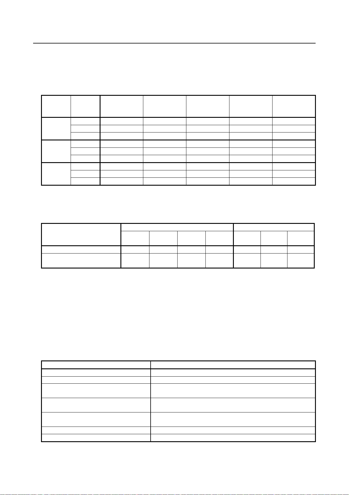
Table 1.1 lists the work outside the safety fence. In this table, the symbol “” means the work allowed to
be carried out by the worker.
Table 1.1 List of work outside the fence
Operator
Turn power ON/OFF to Robot controller
Select operating mode (AUTO, T1, T2)
Select remote/local mode
Select robot program with teach pendant
Select robot program with external device
Start robot program with operator’s panel
Start robot program with teach pendant
Reset alarm with operator’s panel
Reset alarm with teach pendant
Set data on teach pendant
Teaching with teach pendant
Emergency stop with operator’s panel
Emergency stop with teach pendant
Maintain for operator’s panel
Maintain for teach pendant
Programme
Teaching operato
In the robot operating, programming and maintenance, the operator, programmer, teaching operator and
maintenance engineer take care of their safety using at least the following safety protectors.
• Use clothes, uniform, overall adequate for the work
• Safety shoes
• Helmet
or
Maintenance
engineer
- 2 -
Page 9

B-80687EN/15 2. FANUC ROBOT SYSTEM
2 FANUC ROBOT SYSTEM
2.1 PURPOSE OF ROBOT
The FANUC Robot Series can be used for the following applications.
- Spot welding
- Arc welding
- Handling
- Deburring
- Assembling
- Sealing
- Painting
TOOL software appropriate for each application is available. Please consult your FANUC sales
representative if you want to use the robot for any application other than listed above.
Even when you use the robot for the purpose of any of the applications listed above, the robot must NOT
be under any of the conditions listed below. Inappropriate usage of robots may cause not only damage to
the robot system, but also serious injury or even death of the operator and the people in the premises.
• Use of the robot in flammable atmosphere
• Use of the robot in explosive atmosphere
• Use of the robot in radioactive environment
• Use of the robot in water or high humidity environment
• Use of the robot for the purpose of transporting humans or animals
• Use of the robot as a ladder (climbing on the robot)
• Use of the robot outdoors
• Use of the robot under conditions not in accordance with FANUC recommended installation or use
FANUC is not responsible for any damage or accid ent caused by misuse of the robots, such as mentioned
above.
Before using the robot, check the speci fications of the robot, and then take adequate safety measures to
prevent hazardous conditions.
2.2 CONFIGURATION OF ROBOT SYSTEM
The robot system is configured with the following components.
• Robot
• Robot controller
• Teach pendant
• Safety fence
• Interlocked gate
• Interlocking device
• End effector
• Other peripheral equipment
• Workpieces
- 3 -
Page 10

2. FANUC ROBOT SYSTEM B-80687EN/15
WARNING
robot arm.
The components other than the robot, robot controller, and teach pendant must be prepared by the user
according to system configuration.
The FANUC robot has an interface for connection to interlocking devices. Check the specification and
design the interlocking system.
The safety of the following components has been verified by FANUC.
• Robot
• Robot controller and teach pendant
The following component must be prepared by the user according to robot system configuration.
• Safety fence
• Interlocked gate and interlocking device
However, the safety of the following components is not verified by FANUC, due to wide variety of its
design and safety measures.
• End effector
• Workpiece
• Other peripheral equipment
The designer of a robot application system must design the robot system according to safety standards
such as EN ISO 10218 (ANSI RIA ISO 10218) and Annex I of Machinery Directive to secure sufficient
safety.
2.2.1 Robot Training Items
The programmer, teaching operator and maintenance engineer must be trained for the robot operating and
maintenance.
The required items are:
• Basic knowledge
• Safety (laws and regulations, Ordin ance on Industrial Safety and Health, and safety measures),
• Practice of jog feed,
• Practical training of manual operation and teaching of robot,
• Programming practice, teaching and playb ack practice,
• Practice of automatic operation,
• Explanation of configuration and function of robot,
• Explanation and practice of setting up coordinate system,
• Explanation and practice of programming and program example,
• Explanation of interface between robot and peripheral device,
• Explanation and practice of introduction and installation
• Explanation and practice of check item when trouble occur and troubleshooting,
• Explanation and practice of periodical inspection and replacement,
• Explanation and practice of file input and output,
• Explanation and practice of mastering, and
• Explanation and practice of dismantlement and assembly.
Some robot training courses for these i t ems are provided. Please contact us.
Robot operating personnel such as programmers, teaching operators or
maintenance engineers must be trained properly according to the laws and
regulations in the country or area where the robot is installed and used. Without
appropriate training, any work inside the safety fence may cause very sever e
injury or even death of personnel due to hazards such as being pinched by the
- 4 -
Page 11

B-80687EN/15 2. FANUC ROBOT SYSTEM
NOTE
applied.
Dual Check Safety (optional functions)
check
connect
network
R-30iB Plus,
R-30iA Mate
SIL 3
SIL 2
SIL 3
R-J3iB
Cat. 3 (*)
R-J3iB Mate
Cat. 3 (*)
None
(No independent certificate based on this standard)
2.3 RELEVANT STANDARDS
The FANUC Robot Series (for CE marking or NRTL) meets following standards.
[For CE marking : Machinery/Low voltage Dir ect ives]
- EN/ISO 10218-1
- EN 60204-1
- EN/ISO 13849-1 (EN 954-1)
[For NRTL]
- UL 1740
- CAN/CSA Z434
- CSA C22.2 No.73
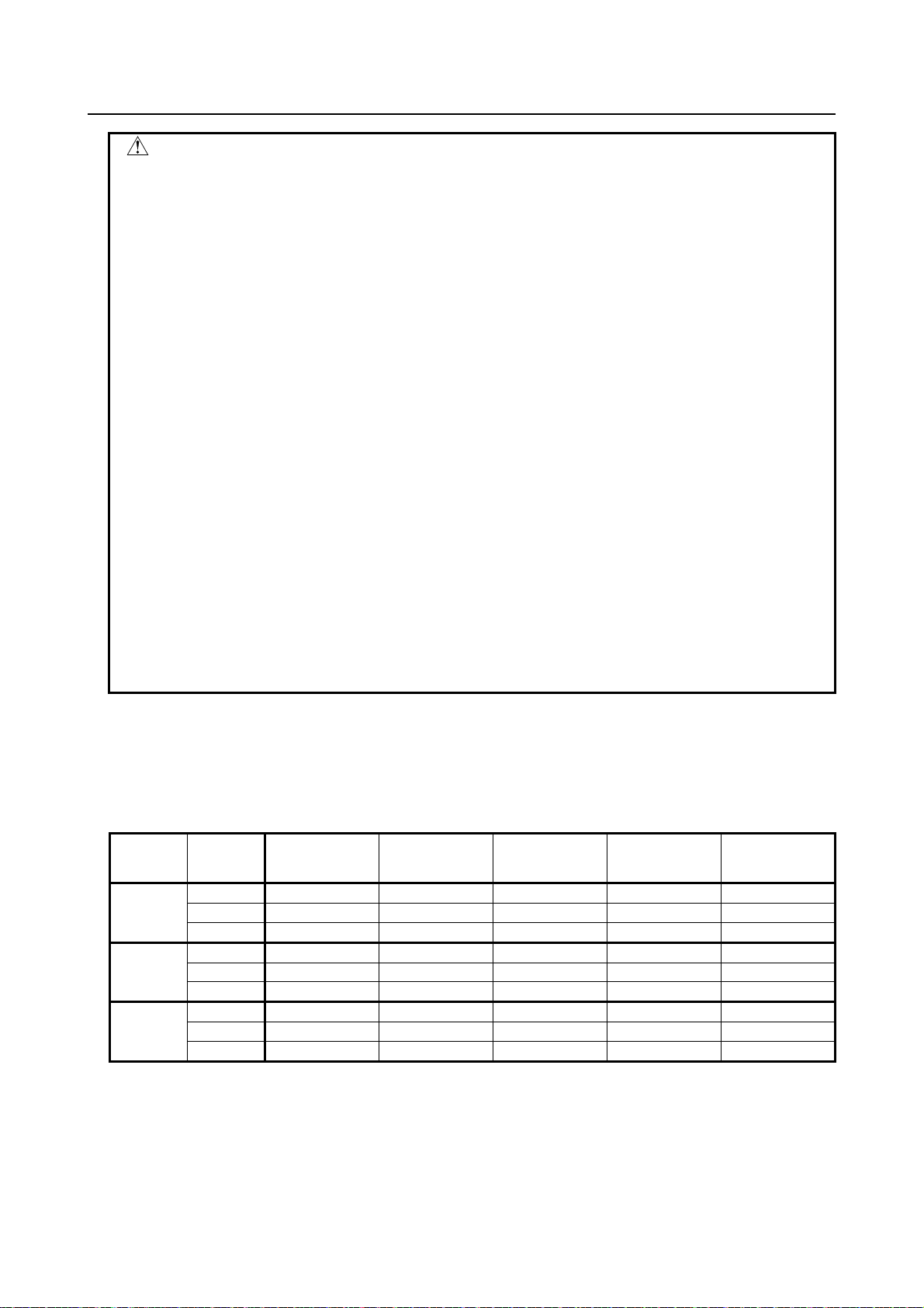
For EN ISO 13849-1 (EN954-1), the following safety categories have been
Controller model
R-30iB Mate Plus,
R-30iB Compact Plus,
R-30iB,
R-30iB Mate,
R-30iA,
(*) Evaluation was included into total safety assessment by third party.
Emergency
stop
[7DA5 or later]
Cat.4
PL e
[7DA1-7DA4]
Cat.4
Cat. 4 or
Position/Speed
[7DA5 or later]
Cat.3
PL d
[7DA1-7DA4]
Cat.3
None
Safe I/O
[7DA5 or later]
Cat.4
PL e
[7DA1-7DA4]
None
Safety
Applied
standard
EN/ISO
13849-1:2008
EN 954-1:1996
[CE marking : For EMC Directive]
- EN 55011 (Group 1, Class A)
- EN 61000-6-2
For the above standards, FANUC robot systems have been certified by the following third parties.
- CE marking : TÜV Rheinland Japan
- NRTL : TÜV SÜD America
- 5 -
Page 12

3. ROBOT SYSTEM DESIGN B-80687EN/15
3 ROBOT SYSTEM DESIGN
In this chapter, requirements for robot system design are described.
- Placement of Equipment
- Power Supply and Protective Earth Connection
- Other Precautions
In addition, the basic requirements for the end effector, workpieces, and peripheral equipment are
outlined in Section 3.5.
About the safety fence, safety gate and other pr otection devices, refer to Sections 4.5 to 4.7.
3.1 GENERAL
The robot system must be designed, constructed, and implemented so that in case of a foreseeable failure
of any single component, whether electrical, electronic, mechanical, pneumatic, or hydraulic, safety
functions are not affected or when they are, the robot system is left in a safe condition (“Failure to
safety”).
Under the intended conditions of use, the discomfort, fatigue and psychological stress faced by the
operator must be reduced to the minimum possible, taking into account ergonomic principles such as:
- allowing for the variability of the operator’s physical dimensions, strength and stamina,
- providing enough space for movements of the parts of the operator’s body,
- avoiding a machine-determined work rate,
- avoiding monitoring that requires lengthy concentration,
- adapting the man/machinery interface to the foreseeable characteristics of the operators.
The application of the electrical equipment o f the ro bot sy stem must be accord ance wi th IEC/ EN60204-1
or NFPA70/NFPA79.
3.2 PLACEMENT OF EQUIPMENT
Please make sure the following requirements are all satisfied for each component of a robot system.
• An appropriate safety fence/guard must be placed according to the safety standards. Refer to
Sections 4.7 and 4.8 for the requirements of the safety fence/guard and protection devices.
• The risk assessment must determine the additional space required beyond the restricted space
(maximum operating area of the robot and end effector) to define the safeguarded space.
• The operator's panel must be located at a safe place:
outside the safety fence, and cannot be r eached from inside the safety fence,
where it can be easily seen, and easily operat ed by the operator,
where the operator can operate it without hesitation or loss of time and without ambiguity, and
where no dangerous situation is created by operating it.
• The operating position must be designed and constructed in such a way as to avoid any risk due to
exhaust gases and/or lack of oxygen.
- 6 -
Page 13

B-80687EN/15 3. ROBOT SYSTEM DESIGN
• If the robot system is intended to be used in a hazardous environment presenting risks to the health
and safety of the operator or if the robot system itself gives rise to a hazardous environment,
adequate means must be provided to ensure that the operator has good working conditions and is
protected against any foreseeable hazards.
• Where appropriate, the operating position must be fitted with an adequate cabin designed,
constructed and/or equipped to fulfill the above requirements. The exit must allow rapid evacuation.
Moreover, when applicable, an emergency ex it must be provided in a direction which is different
from the usual exit.
• A large space must be secured around each component enough for the maintenance and inspection of
the robot system.
• The robot system must be design ed and constructed in su ch a way as to allow access in safety to all
areas where intervention is necessary during operation, adjustment and maintenance.
• The space inside the safety fence, especially for maintenance and inspection, must be designed to
protect the operator from falling off or slipping off the step, and where appropriate, handholds that
are fixed relative to the operator and that enable them to maintain their stability should be prepared.
• The robot system must be secured on a stable floor. Especially the r obot mechanical unit must be
attached to the stable place according to th e instructions in the maintenance manual or operator’s
manual.
• The robot system must be designed to avoid trapping and collision between the moving parts of the
robot and other fixed or moving objects.
• The layouts must be designed in such a way that between moving parts of the robot and objects in
the environment (e.g. pillars of the structure, ceiling joists, fences), sufficient clearance is available.
This rule does not apply to peripheral equipment (such as a conveyer that feeds work pieces) in order
to allow it to perform its task.
• When T2 mode is used, the following clearance is required for robot system installation.
0.45m or more from readily accessible areas of b uildings, structures, utilities, other machines
and equipment not specifically supporting the robot function that may create trapping or a
pinch point
Where this minimum clearance is not provided, additional safeguarding devices is required.
Stop robot motion while personnel are within 0.5m of the trapping or pinch hazard
If these actions are not applied, it may cause in jury of the users.
• When a limitation of the restricted space, by limiting the range of motion of the primary axes (J1, J2,
J3-axes), is required, limiting devices must be provided. They must satisfy one of the following
conditions. (except some models such as Genkotsu robot)
M echanical stopper which are capable of stopping the robot at any adjusted position when it is
carrying its rated load at maximum velocity.
For J2, J3-axis, alternative methods of limiting the range of motion may be provided only if
they are designed, constructed, and installed to achieve the same level of safety as the
mechanical stoppers.
This may include using the limit switches or DCS according to EN/IEC 60204-1 or
NFPA70/NFPA79.
Note that the limiting devices must be correctly adjusted and secured.
- 7 -
Page 14

3. ROBOT SYSTEM DESIGN B-80687EN/15
• When it is intended that operators will perform manual operations associated with the robot, such as
loading and unloading of parts, this must be taken into account in the arrangement of the robot
system, either by providing part loading devices so that the operator cannot access the hazardous
area, or by providing appropriate safeguards for the manual activity.
• Where appropriate and where the working conditions so permit, work stations constituting an
integral part of the robot system must be designed for the installation of seats.
• The operator’s seat must enable him or her to maintain a stable position. Furthermore, the seat and
its distance from the operator's panel must be capable of being adapted to the operator.
• If the robot system is subject to vibrations, the seat must be designed and constructed in such a way
as to reduce the vibrations transmitted to the operator to the lowest level that is reasonably possible.
The seat mounting must withstand all stresses to which they can be subjected, where there is no floor
beneath the feet of the operator, footrests covered with a slip-resistant material must be provided.
• When preparing footstep, please consider security for installation and maintenance work in high
place according to Fig. 3.1. Please consider footstep and safety belt mounting position.
Hook for safety belt
Fence
Steps
Trestle
Pedestal
for maintenance
Fig. 3.2 Pedestal for maintenance
• On transportation of robot mechanical unit or controller, proper transportation procedure described
on operator’s or maintenance manual for each models has to be followed.
WARNING
Follow the procedure specified by FANUC when transporting the robot
mechanical unit or controller. Otherwise, it may fall over due to the loss of the
mechanical stability (balance), resulting in serious injury or death of personnel.
- 8 -
Page 15

B-80687EN/15 3. ROBOT SYSTEM DESIGN
WARNING
(Protective Earth). Without PE connection, electric shock can occur.
3.3 POWER SUPPLY AND PROTECTIVE EARTH
CONNECTION
• The power supply and the protective earth must be connected according to the maintenance manual.
• Unsafe conditions must be avoided in the event of a power down, power recovery after a power
down or supply voltage fluctuations. Unsafe conditions to be avoided are;
Dropping a workpiece or any material,
Safety equipment not functioning, etc.
• The robot system must have means to isolate its power sources. These means must be located in such
a way that no person will be exposed to any hazard, as well as must have a lockout/tagout capability.
The robot mechanical unit and controller have to be properly connected by PE
3.4 OTHER PRECAUTIONS
• Shutdown (removal of power) to the robot system or any peripheral equipment must not result in a
hazardous condition.
• All environmental conditions must be evaluated to ensure compatibility of the robot and the robot
system with the anticipated working conditions. These conditions include explosive mixtures,
corrosive gas and liquid, humidity, dust, temperature, electromagnetic interference (EMI), radio
frequency interference (RFI), and vibration.
• The operating position where the operator stands must be predetermined.
The operating position must satisfy the following conditions.
The operator can easily operate the operator's panel or the teach pendant.
The operator can easily make sure that nobod y is inside the safety fence.
The operator can easily verify the operation of the system.
T he operato r can immediately sto p the entir e or parti al system in the ev ent a malfunction o f the
system or any dangerous condition.
• The following safety measure must be used if the o perator cannot easily verify nobod y is inside the
safety fence, or as required by the risk-assessment result.
A visible/audible war ning device (complying EN/ISO/IEC standards or OSHA) is used before
the robot starts moving.
A measure fo r the person inside the safety fence to stop th e robot system or a measure for the
person to evacuate outside the safety fence.
The robot system is designed and constructed in such a way that starting it is prevented while
someone is in the dangerous zone.
• If necessary, means must be provided to ensure that the robot system can be controlled only from the
operating positions located in one or more predetermined zones or locations.
• When the robot system has two or more operating positions, the robot system must be desig ned in
such a way that the use of one of the operating positions precludes the use of the others, except for
stop controls and emergency stops.
- 9 -
Page 16

3. ROBOT SYSTEM DESIGN B-80687EN/15
CAUTION
of personnel.
• When the robot system has two or more operating positions, each position must be provided with all
the required control devices so that the op erators do not hinder or put each other into a hazardous
situation.
• The manual intervention and reset procedure to restart the robot system after an emergency stop
must take place outside the restricted space.
• A warning device must be such that the operator and other persons in dangerous area can easily
recognize it.
• For UL standard compliance, “a yellow or amber visual indicator” specified by CL 36.1 of UL 1740
was to be installed by the end-user or system manufacturer. SYS RDY or PROGRUN output signals
can be used for installing such a visual indicator.
• The area must be appropriately lighted, especially for maintenance and inspection.
The lighting must not create a new dangerous situation (e.g. dazzled).
• It is recommended that adjustment, greasing or oiling, and other maintenance work can be performed
from outside the dangerous area while the system is stopping.
If it is not feasible, a method to perform these operat i ons safely must be established.
• If the robot and the peripheral equipment synchronously move in the robot system, an appropriate
measure must be provided to avoid hazardous condition by stopping the entire system in the event
any of the equipment stops due to malfunction.
• For robot systems that can be op erated fro m a remote locatio n ( e.g. over a co mmunications network),
a means must be provided (e.g. a key operated switch) to ensure that no commands can initiate
hazardous conditions from the remote location when in local control.
• It is recognized that, for certain phases of the robot system life (e.g. commissioning, process
changeover, cleaning, and maintenance), it may not be possible to design completely adequate
safeguards to protect against every hazard or it may be required for safeguards to be suspended.
Under these conditions, appropriate safe working procedures must be used.
• A robot system manufacturer must provide an operation manual according to EN/ISO 10218 or other
standards.
• The requirements in safety standards (ISO, I EC, JIS, etc.) and the "Ordinance on Industrial Safety
and Health" must be considered when a robot application system is designed.
• Suitable ambient lighting have to be provided near the robot.
Operation inside of the safety fence (teaching, maintenance, etc.) without
suitable ambient lighting can cause hazards of collision (with some obstacles
inside of the safety fence) or slipping/falling down of personnel, resulting in injury
- 10 -
Page 17

B-80687EN/15 3. ROBOT SYSTEM DESIGN
3.5 END EFFECTOR, WORKPIECE AND PERIPHERAL
EQUIPMENT
It is the responsibility of the robot system manufacturer to perform the risk assessment of th e end effect or,
workpiece and peripheral equipment.
This section outlines the basic requirement fo r the risk assessment of these components.
End Effector
• End effectors must be designed and constructed , or safeguarded, so that
power failure does not cause release of the load o r result in a hazardous condition, and
t he static and dynamic forces created by the load and the end effector together are within the
load capacity and dynamic response of the robot.
• If it is equipped with a tool that can function with several different conditions (speed, etc.), the
selection of the condition must be safely and securely done.
Workpiece
• The material and its shape must not be dangerous and if unsafe, safety measures must be provided.
• If the workpiece is in extreme high or low temperature, safety measures must be prov ided to avoid
personnel from touching or getting too close to it.
Peripheral Equipment (including end effector)
• The material and shape must not be dangerous.
• If any component could break down during operation, it must be placed so that it will not scatter if it
breaks down.
• Pipes (for liquid/gas) must have strength enough for its internal / external pressure.
• Pipes must be secured and protected from the external pressure or tension.
• Measures must be provided to avoid a dangerous situation due to sudden movement of the pipe or
the high speed flow of material when a pipe is broken.
• If a pneumatic device is used, an air valve which shuts off the air supply to the robot must be
installed.
• If a power source other than the electricity (e.g. pneumatic, water, heat) is used in the system,
appropriate risk-assessment must be performed, and appropriate safety measures must be provided.
• Be sure to provide safety measures to avoid swapping of components that cause unsafe conditions,
by
design to avoid mount mistakes,
indication of necessary information on the parts.
• Be sure to provide safety measures to avoid poor connections and inferior contacts, by
design to avoid poor connections and inferior contacts
indication of the information on the connectors, pipes, and cables.
• Be sure to provide safety measures to avoid an unsafe condition by touching an extremely high/low
temperature parts (if any).
• Be sure to provide safety measures to avoid fire or explosion through sufficient amount of
investigation.
• Vibration and sound noise must be kept to a minimum with consideration for ambient environment.
• Provide the peripheral equipment with appropriate earth (Class A, Class B, Class C, and Class D).]
• When adjusting each peripheral equipment independently, be sure to turn off the power of the robot.
• If a laser equipment is used, the following must be considered.
Unexpected emission of laser light must be avoided
Direct/indirect emission of light must give no harm to the health
Laser light must give no harm to health during maintenance / adjustment.
- 11 -
Page 18

4. SAFETY DEVICES B-80687EN/15
WARNING
necessary, including the 2 seconds delay.
4 SAFETY DEVICES
4.1 STOP TYPE OF ROBOT (R-30iA, R-30iA Mate)
The following three robot stop types exist:
Power-Off Stop (Category 0 following IEC 60204-1)
Servo power is turned off and the robot stops immediately. Servo power is turned off when the robot is
moving, and the motion path of the deceleration is uncontrolled.
The following processing is performed at Power-Off stop.
- An alarm is generated and servo power is turned off.
- The robot operation is stopped immediately. Execution of the program is paused.
Frequent Power-Off stop of the robot during operation can cause mechanical problems of the robot.
Avoid system designs that require routine or frequent Power-Off stop conditions.
Controlled stop (Category 1 foll owing IEC 60204-1)
The robot is decelerated until it stops, and servo power is turned off.
The following processing is performed at Controlled stop.
- The alarm "SRVO-199 Controlled stop" occurs along with a decelerated stop. Execution of the
program is paused.
- An alarm is generated and servo power is turned off.
Hold (Category 2 following IEC 60204-1)
The robot is decelerated until it stops, and servo power remains on.
The following processing is performed at Hold.
- The robot operation is decelerated until it stops. Execution of the program is paused.
1 The stopping distance and time of Controlled stop is longer than those of
2 In multi arm system, the longest stopping distance and time of Controlled Stop
3 In the system which has extended axis, the longer stopping distance and time of
4 In case of Controlled stop, motor power shutdown is delayed for a maximum of 2
Power-Off stop. A risk assessment for the whole robot system which takes into
consideration the increased stopping distance and stopping time is necessary
when Controlled stop is used. Please refer to the operator's manual of a
particular robot model for the data of stopping distance and time.
among each robot are adopted as those for the system. A risk assessment for
the whole robot system which takes into consideration a possibility that the
stopping distance and time increase, is necessary on the multi arm system.
Controlled Stop among robot and extended axis are adopted as those for the
system. A risk assessment for the whole robot system which takes into
consideration a possibility that the stopping distance and time increase, is
necessary on the system which has extended axis. Please refer to the extended
axis setup procedure of the controller operator’s manual for considering the
stopping distance and time of the extended axis.
seconds. In this case, a risk assessment for the whole robot system is
- 12 -
Page 19
B-80687EN/15 4. SAFETY DEVICES
button
stop
AUTO
P-Stop
P-Stop
C-Stop
C-Stop
P-Stop
A
T1
P-Stop
P-Stop
-
C-Stop
P-Stop
T2
P-Stop
P-Stop
-
C-Stop
P-Stop
AUTO
P-Stop
P-Stop
P-Stop
P-Stop
P-Stop
B
T1
P-Stop
P-Stop
-
P-Stop
P-Stop
T2
P-Stop
P-Stop
-
P-Stop
P-Stop
AUTO
C-Stop
C-Stop
C-Stop
C-Stop
C-Stop
C
T1
P-Stop
P-Stop
-
C-Stop
P-Stop
T2
P-Stop
P-Stop
-
C-Stop
P-Stop
R-30iA
R-30iA Mate
(Single)
(Dual)
type
Standard
B (*) A A A A (**) A A
(A05B-2500-J570)
Alarm
Condition
SRVO-001 Operator panel E-stop
Operator panel emergency stop is pressed.
SRVO-002 Teach pendant E-stop
Teach pendant emergency stop is pressed.
open. (R-30iA controller)
(R-30iA controller)
open. (R-30iA Mate controller)
SRVO-408 DCS SSO Ext Emergency Stop
In DCS Safe I/O connect function, SSO[3] is OFF.
SRVO-409 DCS SSO Servo Disconnect
In DCS Safe I/O connect function, SSO[4] is OFF.
When the emergency stop button is pressed or the FENCE is open, the stop type of robot is Power-Off
stop or Controlled stop. The configuration of stop type for each situation is called stop pattern. The stop
pattern is different according to the controller type or option configuration.
There are the following 3 Stop patterns.
Stop
pattern
Mode
Emergency
stop
External
Emergency
FENCE open SVOFF input
Servo
disconnect
P-Stop: Power-Off stop
C-Stop: Controlled stop
-: Disable
The following table indicates the Stop pattern according to the controller type or option configuration.
Option
Stop type set (Stop pattern C)
Standard
N/A N/A C C N/A C C
Standard
RIA type CE type Standard
RIA
CE type
(*) R-30iA standard (single) does not have servo disconnect.
(**) R-30iA Mate Standard does not have servo disconnect, and the stop type of SVOFF input is
Power-Off stop.
The stop pattern of the controller is d isplayed in "Stop pattern" line in software version screen. Please
refer to "Software version" in operator 's manual of controller for the detail of software version screen.
"Controlled stop by E-Stop" option
When "Stop type set (Stop pattern C) (A05B-2500-J570) option is specified, the stop type of the
following alarms becomes Controlled stop but only in AUTO mode. In T1 or T2 mode, the stop type is
Power-Off stop which is the normal operation of the system.
SRVO-007 External emergency stops
SRVO-194 Servo disconnect
External emergency stop input (EES1-EES11, EES2-EES21) is
Servo disconnect input (SD4-SD41, SD5-SD51) is open.
SRVO-218 Ext.E-stop/Servo Disconnect
External emergency stop input (EES1-EES11, EES2-EES21) is
- 13 -
Page 20

4. SAFETY DEVICES B-80687EN/15
WARNING
distance and stopping time, is necessary when this option is loaded.
Controlled stop is different from Power-Off stop as follows:
- In Controlled stop, the robot is stopped on the program path. This function is effective for a system
where the robot can interfere with other devices if it deviates from the program path.
- In Controlled stop, physical impact is less than Power-Off stop. This function is effective for
systems where the phy sical impact to the mechanical unit or EOAT (End Of Arm Tool) should be
minimized.
- The stopping distance and stopping time of Controlled stop is longer than the stopping distance and
stopping time of Power-Off stop, depending on the robot model and axis. Please refer to the
operator's manual of a particular robot model for the data of stopping distance and stopping time.
For the R-30iA or R-30iA Mate, this function is available only in CE or RIA type hardware.
When this option is loaded, this function cannot be disabled.
The stop type of DCS Position and Speed Check functions is not affected by the loading of this option.
The stopping distance and stopping time of Controlled stop are longer than the
stopping distance and stopping time of Power-Off stop. A risk assessment for
the whole robot system, which takes into consideration the increased stopping
4.2 STOP TYPE OF ROBOT (R-30iB, R-30iB Mate)
There are following four types of Stopping Robot.
Power-Off Stop (Category 0 following IEC 60204-1)
Servo power is turned off, and the robot stops immediately. Servo power is turned off when the robot is
moving, and the motion path of the deceleration is uncontrolled.
“Power-Off stop” performs following processing.
• An alarm is generated, and then the servo power t urns off. Instantly the robot stops.
• Execution of the program is paused.
Frequent Power-Off stop of the robot during operation can cause mechanical problems of the robot.
Avoid system designs that require routine or frequent Power-Off stop conditions.
Controlled stop (Category 1 foll owing IEC 60204-1)
The robot is decelerated until it stops, and servo power is turned off.
“Controlled stop” performs following processing.
• The alarm "SRVO-199 Controlled stop" occurs along with a decelerated stop. The program
• An alarm is generated, and then the servo power t urns off.
Smooth stop (Category 1 following IEC 60204-1)
The robot is decelerated until it stops, and servo power is turned off.
“Smooth stop” performs following processing.
• The alarm "SRVO-289 Smooth Stop" occurs along with a decelerated stop . The program execution
• An alarm is generated, and then the servo power t urns off.
• In Smooth stop, the robot decelerates until it stops with the deceleration time shorter than Controlled
Hold (Category 2 following IEC 60204-1)
The robot is decelerated until it stops, and servo power remains on.
“Hold” performs following processing.
• The robot operation is decelerated until it stops. Execution of the program is paused.
execution is paused.
is paused.
stop.
- 14 -
Page 21
B-80687EN/15 4. SAFETY DEVICES
WARNING
system is necessary, including the 2 seconds delay.
Emergency
button
External
stop
AUTO
P-Stop
P-Stop
C-Stop
C-Stop
-
A
T1
P-Stop
P-Stop
-
C-Stop
P-Stop
T2
P-Stop
P-Stop
-
C-Stop
P-Stop
AUTO
C-Stop
C-Stop
C-Stop
C-Stop
-
C
T1
P-Stop
P-Stop
-
C-Stop
P-Stop
T2
P-Stop
P-Stop
-
C-Stop
P-Stop
AUTO
S-Stop
S-Stop
C-Stop
C-Stop
-
D
T1
S-Stop
S-Stop
-
C-Stop
S-Stop
T2
S-Stop
S-Stop
-
C-Stop
S-Stop
1 The stopping distance and time of Controlled stop and Smooth stop are longer
than those of Power-Off stop. A risk assessment for the whole robot system
which takes into consideration the increased stopping distance and stopping
time is necessary when Controlled stop or Smooth Stop is used. Please refer to
the operator's manual of a particular robot model for the data of stopping
distance and time.
2 In multi arm system, the longest stopping distance and time of Controlled Stop
or Smooth Stop among each robot are adopted as those for the system. A risk
assessment for the whole robot system which takes into consideration a
possibility that the stopping distance and time increase, is necessary on the
multi arm system.
3 In the system which has extended axis, the longer stopping distance and time of
Controlled Stop or Smooth Stop among robot and extended axis are adopted as
those for the system. A risk assessment for the whole robot syst em which takes
into consideration a possibility that the stopping distance and time increase, is
necessary on the system which has extended axis. Please refer to the extended
axis setup procedure of the controller operator’s manual for considering the
stopping distance and time of the extended axis.
4 When Smooth stop occurs during deceleration by Controlled stop, the stop type
of robot is changed to Power-Off Stop.
When Smooth stop occurs during deceleration by Hold, the stop type of robot is
changed to Power-Off Stop.
5 In case of Controlled stop or Smooth Stop, motor power shutdown is delayed for
a maximum of 2 seconds. In this case, a risk assessment for the whole robot
When the emergency stop button is pressed or the FENCE is open, the stop type of robot is Power-Off
stop, Controlled stop, or Smooth stop. The configuration of stop type for each situation is called stop
pattern. The stop pattern is different according to the option configuration.
There are the following 3 Stop patterns.
pattern
P-Stop: Power-Off stop
C-Stop: Controlled stop
S-Stop: Smooth stop
-: Disable
(*) The stop pattern of NTED input is same as Deadman switch.
Stop
Mode
stop
Emergency
FENCE open SVOFF input
Deadman
switch (*)
- 15 -
Page 22

4. SAFETY DEVICES B-80687EN/15
Option
R-30iB/ R-30iB Mate
Standard
A (**)
Controlled stop by E-Stop (A05B-2600-J570)
C (**)
Smooth E-Stop (A05B-2600-J651)
D (**)
Alarm
Condition
SRVO-001 Operator panel E-stop
Operator panel emergency stop is pressed.
SRVO-002 Teach pendant E-stop
Teach pendant emergency stop is pressed.
SRVO-007 External emergency stops
External emergency stop input (EES1-EES11, EES2-EES21) is open.
SRVO-408 DCS SSO Ext Emergency Stop
In DCS Safe I/O connect function, SSO[3] is OFF.
SRVO-409 DCS SSO Servo Disconnect
In DCS Safe I/O connect function, SSO[4] is OFF.
WARNING
when this option is loaded.
The following table indicates the Stop pattern according to the controller type or option configuration.
(**) R-30iB Mate does not have SVOFF input.
The stop pattern of the controller is d isplayed in "Stop pattern" line in software version screen. Please
refer to "Software version" in operator 's manual of controller for the detail of software version screen.
"Controlled stop by E-Stop" option
When "Controlled stop by E-Stop" (A05B-2600-J570) option is specified, the stop type of the following
alarms become Controlled stop but only in AUTO mode. In T1 or T2 mode, the stop type is Power-Off
stop which is the normal operation of the system.
Controlled stop is different from Power-Off stop as follows:
• In Controlled stop, the robot is stopped on the program path. This function is effective for a system
where the robot can interfere with other devices if it deviates from the program path.
• In Controlled stop, physical impact is less than Power-Off stop. This function is effective for
systems where the phy sical impact to the mechanical unit or EOAT (End Of Arm Tool) should be
minimized.
• The stopping distance and time of Controlled stop is longer than those of Power-Off stop, depending
on the robot model and axis.
When this option is loaded, this function cannot be disabled.
The stop type of DCS Position and Speed Check functions is not affected by the loading of this option.
The stopping distance and time of Controlled stop are longer than those of
Power-Off stop. A risk assessment for the whole robot system which takes into
consideration the increased stopping distance and stopping time, is necessary
- 16 -
Page 23

B-80687EN/15 4. SAFETY DEVICES
Alarm
Condition
SRVO-001 Operator panel E-stop
Operator panel emergency stop is pressed.
SRVO-002 Teach pendant E-stop
Teach pendant emergency stop is pressed.
SRVO-003 Deadman switch released
Both deadman switches on Teach pendant are released.
open.
OFF.
SRVO-232 NTED input
NTED input (NTED1-NTED11, NTED2-NTED21) is open.
SRVO-408 DCS SSO Ext Emergency Stop
In DCS Safe I/O connect function, SSO[3] is OFF.
SRVO-409 DCS SSO Servo Disconnect
In DCS Safe I/O connect function, SSO[4] is OFF.
SRVO-410 DCS SSO NTED input
In DCS Safe I/O connect function, SSO[5] is OFF.
SRVO-419 DCS PROFIsafe comm. error
PROFINET Safety communication error occurs.
WARNING
when this option is loaded.
"Smooth E-Stop Function" option
When "Smooth E-Stop Function" (A05B-2600-J651) option is specified, the stop type of the following
alarms becomes Smooth stop in all operation modes (AUTO, T1 and T2 mode).
SRVO-007 External emergency stops
SRVO-037 IMSTP input (Group: %d)
External emergency stop input (EES1-EES11, EES2-EES21) is
IMSTP input (*IMSTP signal for a peripheral device interface) is
Smooth stop is different from Power-Off stop as follows:
• In Smooth stop, the robot is stopped along the program path. This function is effective for a system
where the robot can interfere with other devices if it deviates from the program path.
• In Smooth stop, physical impact is less than Power-Off stop. This functio n is effective for systems
where the physical impact to the mechanical unit or EOAT (End Of Arm Tool) should be
minimized.
• The stopping distance and time of Smooth stop is longer than those of Power-Off stop, depending on
the robot model and axis.
Smooth stop is different from Controlled stop as follows:
• The stopping distance and time of Smooth stop is normally shorter than those of Controlled stop,
depending on the robot model and axis.
When this option is loaded, this function cannot be disabled.
The stop type of DCS Position and Speed Check functions is not affected by the loading of this option.
The stopping distance and time of Smooth stop are longer than those of
Power-Off stop. A risk assessment for the whole robot system which takes into
consideration the increased stopping distance and stopping time, is necessary
- 17 -
Page 24

4. SAFETY DEVICES B-80687EN/15
WARNING
necessary, including the 2 seconds delay.
4.3 STOP TYPE OF ROBOT
(R-30iB Plus, R-30iB Mate Plus, R-30iB Compact Plus)
There are following three types of Stop Category.
Stop Category 0 following IEC 60204-1 (Power-off Stop)
Servo power is turned off, and the robot stops immediately. Servo power is turned off when the robot is
moving, and the motion path of the deceleration is uncontrolled.
“Stop Category 0” performs following processing.
• An alarm is generated, and then the servo power t urns off. Instantly the robot stops.
• Execution of the program is paused.
Frequent Category 0 Stop of the robot during operation can cause mechanical problems of the robot.
Avoid system designs that require routine or frequent Category 0 Stop conditions.
Stop Category 1 following IEC 60204-1 (Controlled Stop, Smooth Stop)
The robot is decelerated until it stops, and servo power is turned off.
“Stop Category 1” performs following processing.
• The alarm "SRVO-199 Controlled stop" or "SRVO-289 Smooth Stop" occurs along with a
decelerated stop. The program execution is paused.
• An alarm is generated, and then the servo power t urns off.
In Smooth stop, the robot decelerates until it stops with the deceleration time shorter than Controlled stop.
The stop type of Stop Category 1 is different according to the robot model or option configuration. Please
refer to the operator's manual of a particular robot model.
Stop Category 2 following IEC 60204-1 (Hold)
The robot is decelerated until it stops, and servo power remains on.
“Stop Category 2” performs following processing.
• The robot operation is decelerated until it stops. Execution of the program is paused.
1 The stopping distance and time of Stop Category 1 are longer than those of Stop
2 In multi arm system, the longest stopping distance and time of Stop Category 1
3 In the system which has extended axis, the longer stopping distance and time of
4 When Stop Category 1 occurs during deceleration by Stop Category 2, the stop
5 In case of Stop Category 1, motor power shutdown is delayed for a maximum of
Category 0. A risk assessment for the whole robot system which takes into
consideration the increased stopping distance and stopping time is necessary
when Stop Category 1 is used. Please refer to the operator's manual of a
particular robot model for the data of stopping distance and time.
among each robot are adopted as those for the system. A risk assessment for
the whole robot system which takes into consideration a possibility that the
stopping distance and time increase, is necessary on the multi arm system.
Stop Category 1 among robot and extended axis are adopted as those for the
system. A risk assessment for the whole robot system which takes into
consideration a possibility that the stopping distance and time increase, is
necessary on the system which has extended axis. Please refer to the extended
axis setup procedure of the controller operator’s manual for considering the
stopping distance and time of the extended axis.
type of robot is changed to Stop Category 0.
2 seconds. In this case, a risk assessment for the whole robot system is
- 18 -
Page 25
B-80687EN/15 4. SAFETY DEVICES
Emergency
button
External
stop
AUTO
Category 0
Category 0
Category 1
Category 1
-
A
T1
Category 0
Category 0
-
Category 1
Category 0
T2
Category 0
Category 0
-
Category 1
Category 0
AUTO
Category 1
Category 1
Category 1
Category 1
-
C
T1
Category 0
Category 0
-
Category 1
Category 0
T2
Category 0
Category 0
-
Category 1
Category 0
AUTO
Category 1
Category 1
Category 1
Category 1
-
D
T1
Category 1
Category 1
-
Category 1
Category 1
T2
Category 1
Category 1
-
Category 1
Category 1
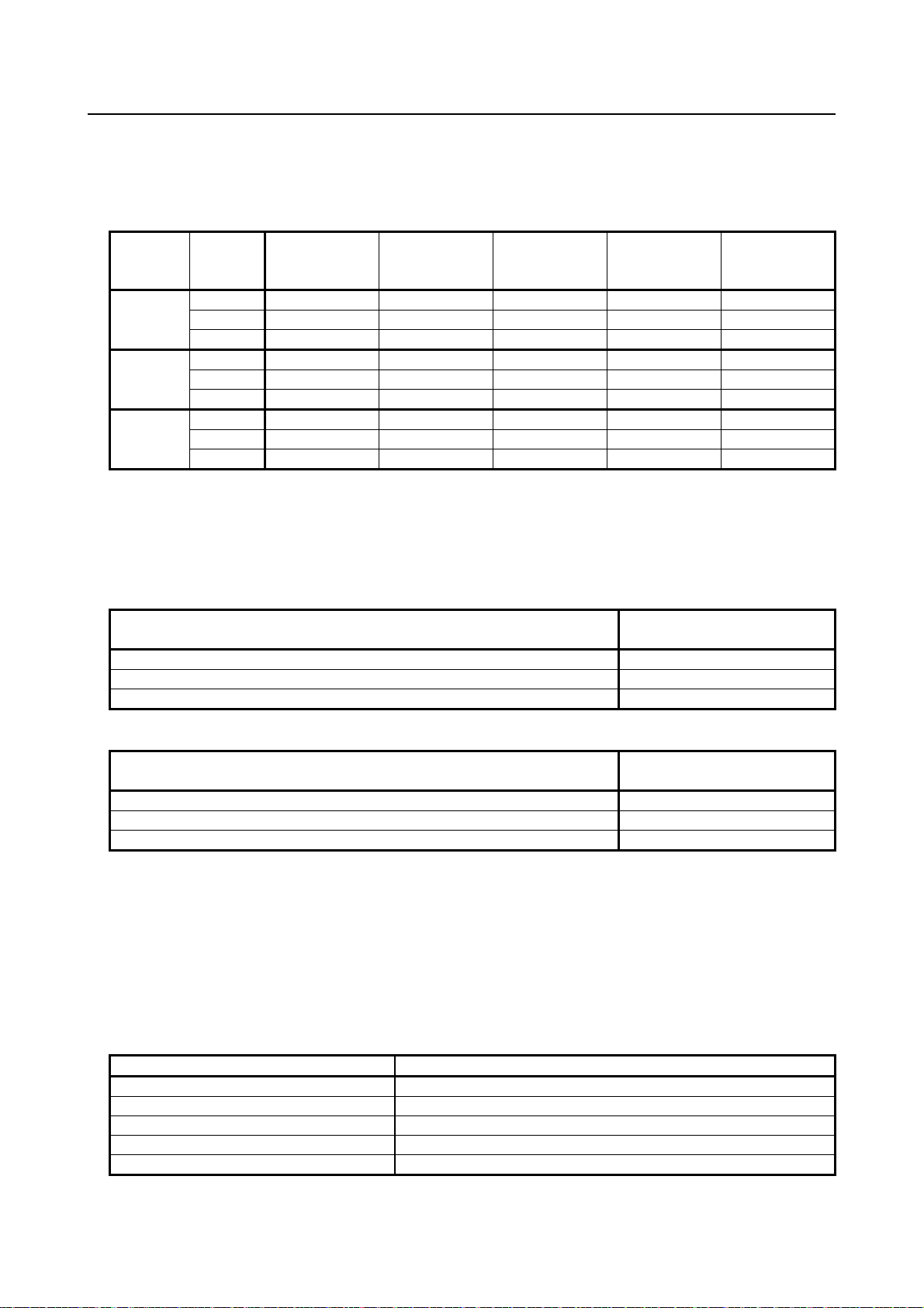
R-30iB Plus/ R-30iB Mate Plus/
R-30iB Compact Plus
Standard
C (**)
Old Stop Function (A05B-2670-J680)
A (**)
All Smooth Stop Function (A05B-2670-J651)
D (**)
R-30iB Plus/ R-30iB Mate Plus/
R-30iB Compact Plus
Standard
A (**)
Stop Category 1 by E-Stop (A05B-2670-J521)
C (**)
All Smooth Stop Function (A05B-2670-J651)
D (**)
Alarm
Condition
SRVO-001 Operator panel E-stop
Operator panel emergency stop is pressed.
SRVO-002 Teach pendant E-stop
Teach pendant emergency stop is pressed.
SRVO-007 External emergency stops
External emergency stop input (EES1-EES11, EES2-EES21) is open.
SRVO-408 DCS SSO Ext Emergency Stop
In DCS Safe I/O connect function, SSO[3] is OFF.
SRVO-409 DCS SSO Servo Disconnect
In DCS Safe I/O connect function, SSO[4] is OFF.
When the emergency stop button is pressed or the FENCE is open, the stop type of robot is Stop Category
0 or Stop Category 1. The configuration of stop type for each situation is called stop pattern. The stop
pattern is different according to the option configuration.
There are the following 3 Stop patterns.
Stop
pattern
Mode
stop
Emergency
FENCE open SVOFF input
Deadman
switch (*)
Category 0: Stop Category 0
Category 1: Stop Category 1
-: Disable
(*) The stop pattern of NTED input is same as Deadman switch.
The following table indicates the Stop pattern according to the controller type or option configuration.
The case R651 is specified.
Option
The case R650 is specified.
Option
(**) R-30iB Mate Plus and R-30iB Compact Plus do not have SVOFF input.
The stop pattern of the controller is d isplayed in "Stop pattern" line in software version screen. Please
refer to "Software version" in operator's manual of controller for the detail of software version screen.
"Old Stop Function" option
When "Old Stop Function" (A05B-2670-J680) option is specified, the stop type of the following alarms
becomes Stop Category 0 in AUTO mode.
- 19 -
Page 26

4. SAFETY DEVICES B-80687EN/15
Alarm
Condition
SRVO-001 Operator panel E-stop
Operator panel emergency stop is pressed.
SRVO-002 Teach pendant E-stop
Teach pendant emergency stop is pressed.
SRVO-003 Deadman switch released
Both deadman switches on Teach pendant are released.
open.
SRVO-037 IMSTP input (Group: %d)
IMSTP input (*IMSTP signal for a peripheral device interface) is ON.
SRVO-232 NTED input
NTED input (NTED1-NTED11, NTED2-NTED21) is open.
SRVO-408 DCS SSO Ext Emergency Stop
In DCS Safe I/O connect function, SSO[3] is OFF.
SRVO-409 DCS SSO Servo Disconnect
In DCS Safe I/O connect function, SSO[4] is OFF.
SRVO-410 DCS SSO Ext Emergency Stop
In DCS Safe I/O connect function, SSO[5] is OFF.
SRVO-419 DCS PROFIsafe comm. error
PROFINET Safety communication error occurs.
WARNING
when this option is loaded.
Stop Category 0 is different from Stop Category 1 as follows:
• In Stop Category 0, servo power is turned off, and the robot stops immediately. Servo power is
turned off when the robot is moving, and the motion path of the deceleration is uncontrolled.
• The stopping distance and time of Stop Category 0 is shorter than those of Stop Category 1,
depending on the robot model and axis.
When this option is loaded, this function cannot be disabled.
The stop type of DCS Position and Speed Check functions is not affected by the loading of this option.
"All Smooth Stop Function" option
When "All Smooth Stop Function" (A05B-2670-J651) option is specified, the stop type of the following
alarms becomes Stop Category 1 in all operation modes (AUTO, T1 and T2 mode).
SRVO-007 External emergency stops
External emergency stop input (EES1-EES11, EES2-EES21) is
Stop Category 1 is different from Stop Category 0 as follows:
• In Stop Category 1, the robot is stopped along the program path. This function is effective for a
system where the robot can interfere with other devices if it deviates from the program path.
• In Stop Category 1, physical impact is less than Stop Category 0. This function is effective for
systems where the physical impact to the mechanical unit or EOAT (End of Arm Tool) should be
minimized.
• The stopping distance and time of Stop Category 1 is longer than those of Stop Category 0,
depending on the robot model and axis.
When this option is loaded, this function cannot be disabled.
The stop type of DCS Position and Speed Check functions is not affected by the loading of this option.
The stopping distance and time of Stop Category 1 are longer than those of Stop
Category 0. A risk assessment for the whole robot system which takes into
consideration the increased stopping distance and stopping time, is necessary
- 20 -
Page 27

B-80687EN/15 4. SAFETY DEVICES
Alarm
Condition
SRVO-001 Operator panel E-stop
Operator panel emergency stop is pressed.
SRVO-002 Teach pendant E-stop
Teach pendant emergency stop is pressed.
SRVO-007 External emergency stops
External emergency stop input (EES1-EES11, EES2-EES21) is open.
SRVO-408 DCS SSO Ext Emergency Stop
In DCS Safe I/O connect function, SSO[3] is OFF.
SRVO-409 DCS SSO Servo Disconnect
In DCS Safe I/O connect function, SSO[4] is OFF.
WARNING
when this option is loaded.
"Stop Category 1 by E-Stop" option
When "Stop Category 1 by E-Stop" (A05B-2670-J521) option is specified, the stop type of the
following alarms become Category 1 Stop but only in AUTO mode. In T1 or T2 mode, the stop type is
Category 0 Stop which is the normal operation of the system.
Stop Category 1 is different from Stop Category 0 as follows:
• In Stop Category 1, the robot is stopped along the program path. This function is effective for a
system where the robot can interfere with other devices if it deviates from the program path.
• In Stop Category 1, physical impact is less than Stop Category 0. This function is effective for
systems where the physical impact to the mechanical unit or EOAT (End of Arm Tool) should be
minimized.
• The stopping distance and time of Stop Category 1 is longer than those of Stop Category 0,
depending on the robot model and axis.
When this option is loaded, this function cannot be disabled.
The stop type of DCS Position and Speed Check functions is not affected by the loading of this option.
The stopping distance and time of Stop Category 1 are longer than those of Stop
Category 0. A risk assessment for the whole robot system which takes into
consideration the increased stopping distance and stopping time, is necessary
- 21 -
Page 28

4. SAFETY DEVICES B-80687EN/15
WARNING
location(s) based on the system layout.
4.4 EMERGENCY STOP
This robot has following emergency stop devices.
• emergency stop button (located on the operator's panel and teach pendant)
• external emergency stop input signal (a terminal is provided)
When the emergency stop button is pushed, the robot stops immediately (refer to Section 4.1 to 4.3).
The external emergency stop input signal is input from peripheral devices.
The signal terminal is provided inside the robot controller.
Refer to the maintenance manual for each controller for the actual position of the emergency stop button.
1 Operator’s panels and teach pendants are option for some controllers. If robot
2 If you operate robots with except operator’s panels or teach pendants, install
does not have an operator’s panel and a teach pendant, emergency stop button
is not installed when the robot is shipped. Be sure to connect external
emergency stop input signal to one or more peripheral equipment and make
emergency stop function.
EMERGENCY STOP button(s) within the operator’s reach in appropriate
- 22 -
Page 29

B-80687EN/15 4. SAFETY DEVICES
T2
T1
AUTO
panel, the teach pendant enable switch and the remote condition on the software.
4.5 MODE SELECT SWITCH
In the case of R-J3iB or later, The MODE SELECT switch is installed on the operator's panel of the robot
controller. (This is option for some controller.) You can select one of the operating modes using this
switch. The selected operating mode can be locked by removing its key.
Whenever the mode is changed by this switch, the robot stops and a message indicating that the operating
mode is changed is shown in the teach pendant LCD.
Fig. 4.5 Example of MODE SELECT Switch
4.5.1 Operating Modes
There are two or three operating modes, which are shown below.
AUTO Mode
• The robot program can be started from the operator’s panel.
• The robot program can be started from the peripheral device I/O.
• The safety fence is enabled (when the fence is opened, emergency stop occurs).
• The robot can be operated at the specified maximum speed.
T1 Mode
• The robot program can only be started from the teach pendant.
• The robot cannot be operated at speeds higher than 250mm/s both at the tool center point in the tool
coordinate system (zero point of the tool coordinate system) and the center of the flange.
• The safety fence is disabled (even when the fence is opened. the robot does not stop).
T2 Mode (Optional)
• The robot program can only be started from the teach pendant.
• The robot can be operated at the specified maximum speed.
• The safety fence is disabled (even when the fence is opened. the robot does not stop)
The teach pendant, operator panel, and peripheral equipment inter face send each robot start signal. However the
validity of each signal changes as follows depending on the mode switch and the DEADMAN switch of the operator
- 23 -
Page 30

4. SAFETY DEVICES B-80687EN/15
condition
Local
Not allowed
Not allowed
Not allowed
Remote
Not allowed
Not allowed
Not allowed
Local
Not allowed
Allowed to start
Not allowed
Remote
Not allowed
Not allowed
Allowed to start
Local
Allowed to start
Not allowed
Not allowed
Remote
Allowed to start
Not allowed
Not allowed
Local
Not allowed
Not allowed
Not allowed
Remote
Not allowed
Not allowed
Not allowed
Mode
AUTO mode
T1, T2 mode
T1, T2 mode: DEADMAN switch is effective.
Teach pendant
enable switch
On
Off
On
Off
Software
remote
Teach pendant O perator panel
Peripheral
equipment
Refer to the operator’s manual of the robot controller for detail.
4.6 DEADMAN SWITCH
The deadman switch is used as an “enabling device”.
When the teach pendant is enabled, robot motion is allowed only while at least one of deadman switches
is gripped. If you release or hard grip switches, the robot stops immediately.
Fig. 4.6 Deadman switch
Based on the risk assessment by FANUC, the number of operations of t he deadman switches should not
exceed about 10000 times per year.
- 24 -
Page 31

B-80687EN/15 4. SAFETY DEVICES
WARNING
due to hazards such as being pinched by the robot arm.
4.7 SAFEGUARDS
The safeguards consist of:
• safety fence (fixed guard),
• safety gate (with interlocking devices),
• safety plug and socket, and
• other protection devices.
These safety devices must be complied with the safety standards such as ISO and IEC. They are also
installed by the system engineer.
This section describes the requirements for these safety devices.
Refer to EN/ISO 10218 and other related standards for detail.
Suitable safety guards have to be installed around the robot system. Robot
operation without safety guards can cause serious injury or death of personnel
4.7.1 Safety Fence
The requirements for the safety fence are as follows.
- The fence is constructed to withstand foreseeable operational and environmental forces.
- The fence is free of sharp edges and projection and is not itself a hazard.
- The fence prevents access to the safeguarded space except through openings equipped with
interlocking devices or presence sensing devices.
- The fence is permanently fixed in position and is removable only with the aid of tools.
- The fixing system of th e safety fen ce must remain attached to th e safety fen ce or to the robot system
when they are removed.
- Where possible, the safety fence must be fixed at a given place and cannot be moved.
- The fence must cause minimum obstruction to the view of the production process. (Wire mesh,
grating, or panel fence)
- The fence is located at an ad equate distance from the maximum space of the robot.
- The fence should be connected to PE (protective earth) to prevent the electric shock.
- Refer to the following and their related stand ards for details such as the size of the opening and th e
minimum size of the grating.
- EN ISO 13855
- EN ISO 13857
- ANSI B11.19
- 25 -
Page 32

4. SAFETY DEVICES B-80687EN/15
4.7.2 Safety Gate and Plugs
The requirements for the safety gate are as follows.
- The interlock prevents the robot system from automatic operation until the guard is closed.
- The closure of the guard must not be the control to restart automatic operation. This must be a
deliberate action at a control station.
- The gate must be equipped with plugs and sockets for interlock. The plugs and sockets must be
selected appropriate ones for safety.
This guard must remain locked and closed until the risk of injury from the hazard has ceased (interlocking
guard with guard locking). Alternatively, when the guard is opened while the robot sy stem is working, a
stop or emergency stop instruction (interlocking guard) is given.
Refer to EN/ISO 14119 or ANSI B11.19 for details of the interlocking devices.
It is recommended to install a device p reventing the gate from being accidentally closed when personnel
can fully enter the safeguarded space though the gate with interlocking devices.
Care should be taken to ensure that actuation of an interlock installed to protect against on hazard (e.g.
stopping hazardous motion of the robot system) does not create other hazards (e.g. the release of
hazardous substances into the work zone).
4.7.3 Other Protection Devices
Protection devices must be designed and incorporated into the control system so that:
- moving parts cannot start up while they are within the operator’s reach,
- the person cannot reach moving parts once they have started up,
- they can be adjusted only by means of an intentional action, such as the use of a tool, key, etc.,
- the absence or failure of one of their components prevents starting or stops the moving parts.
If some presence sensing devices are used for safety purposes, they must comply with the following.
- A presence sensing device must be installed and arrang ed so th at perso ns canno t enter an d reach into
a hazardous area without activating the d evice.
- A presence sensing device must be installed and arranged so that perso ns cannot reach the restricted
space before the hazardous conditions have ceased.
- Barriers used in conju nction with the presence-sensing device may be required to prevent persons
from bypassing the device.
- Their operation must not be adversely affected by any of the environmental conditions for which the
system was intended.
- When a presence sensing device has been activated, it may be possible to restart the robot system
from the stopped position provided that this does not create other hazards.
- Resumption of robot motion must require the removal of the sensing field interruption. This must
not be the control to restart automatic operation.
- 26 -
Page 33

B-80687EN/15 4. SAFETY DEVICES
WARNING
robot arm.
4.8 OPERATION INSIDE OF THE SAFETY FENCE
When some workers (programmer, maintenance engineer) have to en ter the safety fence, the following
care has to be taken into account.
Make sure that the robot has been completely stopped before entering the safety fence.
Never enter the safety fence during the robot moving. If the robot is moving, stop the robot by
the hold button (or input signal), and after "controlled stopping" or “smooth stopping” it (servo
power off), then you can enter the safety fence.
Make sure that an indicator lamp for stop condition shows the stopped status of the robot, and
enter the safety fence from the safety gate.
To inform you are working in the safety fence, display “working”. During robot teaching or test
operation, robot may move to an unexpected direction. So exercise special care, and perform
teaching in the position where you can escape from the robot in case of dangerous situation.
Set the "safe reduced speed" signal enabled.
When more than one worker collaborates for their operation, a person in charge should be
equipped with the teach pendant, and other workers have to follow his or her order.
Any operations from the external interface and robot controller operator's panel without his or
her order have to be prohibited.
Al l workers inside of the safety fence always hav e to secure the escape zone to avoid hazards
from unintended movement of the robot.
Care should be taken by all workers no t to close off the escape routes for each other.
Do not operate the robot while resting against the wall, app aratus installed inside of t he safety
fence, etc. that take away the escape zone from the operator.
Keep watching the robot during operation in jogging, program verification, etc.
Stop the robot immediately by the E-stop button when somebody recognizes dangerous
situation.
Whenever possible, other operator who is readily accessible to the E-stop button keeps watch
from the outside of the safety fence.
Make sure that a deadman SW is operated only by holding it with a hand.
Make sure that nobody still exists in side of the safety fence when closing the safety gate.
Do not leave tools etc. inside of the motion range of the robot or peripheral devices when
operation inside of the safety fence has been finished.
1 Safety procedures for entering the safety fence have to be established and
observed. Improper procedure for entering the safety fence can cause serious
injury or death of personnel due to hazards such as being pinched by the robot
arm.
2 During teaching or maintenance of the robot system, special care shall be taken
so that any other personnel who is not work for these operations does not enter
the safety fence. Unauthorized entry to the inside of the safety fence can cause
serious injury or death of personnel due to hazards such as being pinched by the
- 27 -
Page 34

4. SAFETY DEVICES B-80687EN/15
Safety plug 1 must be inserted into socket 3 inside the fence.
4.9 SAFETY PROCEDURES FOR ENTERING THE SAFETY
FENCE
This section describes an example of the safety p rocedures for entering the safety fence.
Note that only a programmer or a maintenance engineer can enter the safety fence. Any other person
(including an operator) CANNOT enter the safety fence.
Entering into the SAFETY FENCE
Situation: The robot is moving automatically (in AUTO mode).
1 Stop the robot by pressing the [HOLD] button or the HOLD input signal.
2 Change the operating mode to T1 or T2 from AUTO with the MODE SELECT switch.
3 Remove the key to the MODE SELECT switch for mode lock.
4 Remove safety plug 2 from socket 2.
5 Open the safety gate of the safety fence, and insert safety plug 2 removed in step 4 into socket 4.
6 Remove safety plug 1 from socket 1.
7 Enter inside the safety fence, and insert safety plug 1 removed in step 6 into socket 3.
Refer to Fig.4.9 for details of the safety fence, safety plug, and socket configurations.
The key to the MODE SELECT switch and safety plug 1 must be carried into the safety fence by the person
entering the fence.
- 28 -
Page 35

B-80687EN/15 4. SAFETY DEVICES
Fig. 4.9 Safety Fence and Safety Gate example
- 29 -
Page 36

5. GENERAL CAUTIONS B-80687EN/15
WARNING
robot arm.
CAUTION
injury due to the high temperature portion.
5 GENERAL CAUTIONS
In this chapter, the requirements for safety during the following situations are described:
- Installation (5.1)
- Commissioning and functional testing (5.2)
- Precaution for mechanism (5.3)
- Programming (5.4)
- Program verification (5.5)
- Troubleshooting (5.6)
- Saving programmed data (5.7)
- Automatic operation (5.8)
- Maintenance (5.9)
- Safety of maintenance engineer (5.10)
- Dismantling / scrapping (5.11)
- Other cautions (5.12)
The user must ensure that the safeguarding methods are provided, utilized, and maintained for each
operation associated with the robot system and in particular for personnel other than those utilizing the
teach pendant or enabling device.
The user must ensure that a teach pendant not connected to the robot controller must be in accessible.
1 Safety procedures for entering the safety fence have to be established and
2 During teaching or maintenance of the robot system, special care shall be taken
The servo motors, the regenerative resistor units and the isolated tr ansformers
When touching any of these components is nonetheless required (ex.: for
5.1 INSTALLATION
The robot system must be installed in accordance wi t h FANUC’s requirements. The safeguarding
methods must be identified by the hazard anal ysis and the risk assessment. The user must review the
safety requirements to ensure that the appropriate safeguards are applied and operational prior to use in
production.
observed. Improper procedure for entering the safety fence can cause serious
injury or death of personnel due to hazards such as being pinched by the robot
arm.
so that any other personnel who is not work for these operations does not enter
the safety fence. Unauthorized entry to the inside of the safety fence can caus e
serious injury or death of personnel due to hazards such as being pinched by the
on the AC power supply may be hot even after robot operation. Touching the
surface of these components should be therefore avoided as much as possible.
maintenance purposes), special care must be applied in order to avoid burn
- 30 -
Page 37

B-80687EN/15 5. GENERAL CAUTIONS
5.2 COMMISSIONING AND FUNCTIONAL TESTING
Specify the procedures that must be followed during the testing of robots or robot systems after
installation or relocation. These procedures are also applied to robot s or robot systems after modificati ons
(e.g. changes in hardware or software, r eplacement of p arts, adj ustments) and after maintenan ce or rep airs
that can adversely affect their safe operation.
5.2.1 Designation of the Restricted Space
When the safeguarding methods are not in place prior to commissioning and functional testing, interim
means of designating the restricted space must be in place before proceeding.
5.2.2 Restriction of Personnel
During the commissioning and functional testing, personnel must not be allowed in the safeguarded space
until the safeguards are functional.
5.2.3 Safety and Operational Verification
Follow the instructions by the manufacturer (FANUC) for the commissioning and functional testing of
the robot or the robot system.
At the initial start-up, the following matters must be included (but not limited to).
Before applying power, verify that
- the robot has been properly mechanically mounted and is stable,
- the electrical connections are correct and the power supply (i.e. voltage, frequency, interference
levels) is within specified limits,
- the other utilities (e.g. water, air, gas) are pro perly connected and within specified limits,
- the peripheral equipment is properly connected,
- the limiting devices that establish the restricted space (when utilized) are installed,
- the safeguarding means are applied, and
- the physical environment is as specified (e.g. lighting and noise levels, temperature, humidity,
atmospheric contaminants).
After applying power, verify that
- the start, stop, and mode selection control devices function as intended,
- each axis moves and the movement of the axis is restricted as intended,
- emergency stop circuits and devices are function correctly,
- the safeguards and interlocks function correctly,
- it is possible to disconnect and isolate the external power sources,
- the teach and playback facilities function correctly,
- other safeguarding is in place (e.g. barriers, warning devices),
- in safe reduced speed, the robot operates properly and has the capability to handle the product or
workpiece, and
- in automatic (normal) operation, the robot operates properly and has the capability to perform the
intended task at the rated speed and load.
5.2.4 Robot System Restart Procedures
A procedure for the restart of the robot sy stem after hardware, software or task program modification,
repair, or maintenance must include but not necessarily be limited to the following:
- check any changes or additions to the hardware prior to applying power;
- functionally test the robot system for proper operation.
- 31 -
Page 38

5. GENERAL CAUTIONS B-80687EN/15
5.3 PRECAUTIONS FOR MECHANISM
(1) Keep the component cells of the robot system clean, operate the robot where insulated from the
influence of oil, water, and dust.
(2) Don’t use unconfirmed liquid for cutting fluid and cleaning fluid.
(3) Adopt limit switches or DCS or mechan ical stoppers to limit the robot motion, and avoid the robot
from collisions against peripheral equipment or tools.
(4) Observe the following precautions about the mechanical u nit cables. Failure to follow precautions
may cause problems.
• Use mechanical unit cable that have required user interface.
• Do not add user cable or hose to inside of the mechanical unit.
• Please do not obstruct the movement of the mechanical unit when cables are added to o utside
of mechanical unit.
• In the case of the model that a cable is exposed, please do not perform remodeling (Adding a
protective cover and fix an outside cable more) obstructing the behavior of the outcrop of the
cable.
• When installing user peripheral equipment on the robot mechanical unit, please pay attention
that the device does not interfere with the robot itself.
(5) The frequent power-off stop for the robot during operation causes the trouble of the robot. Please
avoid the system construction that power-off stop would be operated routinely. (Refer to bad case
example.) Please perform power-off stop after reducing the speed of the robot and stopping it by
hold stop or cycle stop when it is not urgent. (Please refer to "STOP TYPE OF ROBOT" in Chapter
4 for detail of stop type.)
(Bad case example)
• Whenever poor product is generated, a line stops by emergency stop and power-off of the robot
is incurred.
• When alteration is necessary, safety switch is operated by opening safety fence and power-off
stop is incurred for the robot during operation.
• An operator pushes the emergency stop button frequently, and a line stops.
• An area sensor or a mat switch conn ected to safety signal operates routinely and power-off stop
is incurred for the robot.
• Power-off stop is regularly incurred due to an inappropriate setting for Dual Check Safety
(DCS).
(6) Power-off stop of Robot is executed when collision detection alarm (SRVO-050) etc. occurs. Please
try to avoid unnecessary power-off stops. It may cause the trouble of the robot, too. So remove the
causes of the alarm.
- 32 -
Page 39

B-80687EN/15 5. GENERAL CAUTIONS
WARNING
by the robot arm.
5.4 PROGRAMMING
Whenever possible, programming must be performed with all persons outside the safeguarded space.
When it is necessary to perform programming with personnel inside the safeguarded space, the following
safety procedures are necessary.
No other personnel than a programmer or teaching operator enter the safety
fence during teaching. Unauthorized entry to the inside of the safety fence can
cause serious injury or death of personnel due to hazards such as being pinched
5.4.1 Prior to Programming
The following matters must be met prior to programming.
- The programmer must be trained on the type of robot used in the actual robot system and must be
familiar with the recommended programming procedures including all of the safeguarding methods.
- The programmer must visually check the robot system and safeguarded space to ensure that
extraneous conditions which can cause hazards do not exist.
- Where required for programming, the teach pendant must be tested to ensure proper operation.
- Any faults or failures in the robot system must be corrected prior to starting programming.
- Before entering the safegu arded sp ace, the p rogrammer must ensure that all necessary safeg uards are
in place and functioning correctly.
- The programmer must set the operating mode T1 (or T2) from AUTO and must take any measure to
prevent other personnel from initiating automatic operation prior to entering the safeguarded space.
- Operators should be ungloved while manipulating the operator panel or teach pendant. Operation
with gloved fingers could cause an operation error.
5.4.2 During Programming
During programming, only the programmer must be allowed in the safeguarded space and the following
conditions must be met.
- The robot system must be under the sole control of the programmer within the safeguarded space.
- The controls of the teach pendant must be used as intended.
- The robot system must not respond to any remote commands or conditions that would cause
- Movement of other equ ipment in the safeguarded space which can present a hazard must either be
- All robot system emergency sto p devices must remain functional. When they are not functional, a
5.4.3 Returning to Automatic Operation
The programmer must return the suspended safeguards to their original effectiveness prior to initiating
automatic operation of the robot system.
(When T1 or T2 mode is selected, the robot can be moved only by the teach pendant.)
hazardous conditions.
prevented or under the sole control of the programmer. When under control of the programmer, it
must require a delib erate action on the part of the programmer separate from the action to initiate
robot motion.
measure must be taken so that the safety of personnel is ensured.
- 33 -
Page 40

5. GENERAL CAUTIONS B-80687EN/15
5.5 PROGRAM VERIFICATION
When visual examination of the robot system response to the task program is necessary as part of the
verification procedure, it should be made with all persons outside the safeguarded space. When it is
necessary to perform program verification with personnel inside the safeguarded space, the following
must apply.
- Program verification must initially be performed at safe reduced speed.
Caution must be exercised particularly when override is specified in the program.
- When it is necessary to examine the movement of the robot at full (operational) speed, the following
requirements must apply:
Suspension of the safe reduced speed must be done only by the programmer using means that
require a deliberate action;
An enabling device or a device with an equivalent safety level must always be available to
personnel within the safeguarded space;
Safe wo rk procedures are established to minimize the exposure o f personnel to hazards within
the safeguarded space.
- When a program is completed, be sure to carry out a test operation according to the following
procedure.
(a) Run the program for at least one operati on cycle in the single step mode at low speed.
(b) Run the program for at least one operation cycle in continuous operation at low speed.
(c) Run the program for one operation cycle in continuous operation at the intermediate speed and
check that no abnormalities occur due to a delay in timing.
(d) Run the program for one operation cycle in continuous operation at the normal operating speed
and check that the system operates automatically without trouble.
(e) After checking the completeness of the program through the test operation above, execute it in
the automatic operation.
- While operating the system in the automatic operation, the programmer should leave the safety
fence.
5.6 TROUBLESHOOTING
Troubleshooting must be performed from outside the safeguarded space. When this is not practicable, and
the robot system has been designed to perform troubleshooting from within the safeguarded space, the
following requirements must apply:
- Personnel responsible for troubleshooting are specifically authorized and trained for these activ ities;
- Personnel entering t he safeguarded space must use the enabling device to allow motion of the robot;
- Safe work procedures are established to minimize the exposur e of personnel to hazards within the
safeguarded space.
5.7 STORING PROGRAMMED DATA
A record of the task programs together with any modifications should be stored.
The media to which programmed data are saved must be stored in a suitably protected environment when
not in use.
- 34 -
Page 41

B-80687EN/15 5. GENERAL CAUTIONS
WARNINIG
situation, which can lead them to serious injury or death.
WARNING
high-voltage part.
5.8 AUTOMATIC OPERATION
Automatic operation must only be permissible when
- the intended safeguards are in place and functioning normally,
- no personnel are pr esent within the safeguarded space, and
- proper safe work procedures are provided and followed.
Make sure that nobody remained inside the safety fence before starting up
automatic operation of the robot system. If automatic operation is performed
while somebody is still inside the safety fence, he or she might meet serious
5.9 MAINTENANCE
An inspection and maintenance procedure manual for the robot and robot system must be prepared to
ensure their continued safe operation. The inspection and maintenance procedure manual must be
prepared with the robot and robot system manufacturer’s recommendations taken into account.
Personnel who perform maintenance or repair on robots or a robot system must be sufficiently trained in
the procedures necessary to safely perform the required tasks.
Personnel who perform maintenance or repair on the robot system must be safeguarded from hazards.
Where possible, maintenance must be performed from outside th e safeguarded space with the robot arm
placed in a predetermined position.
The following is the safety procedu re for entering the safeguarded space when it is necessary to perform
maintenance within the safeguarded space.
Power to the robot system has to be disconnected by the main breaker
1 Stop the robot system.
2 Shut off the power to the robot system, and lock the main breaker to prevent powering on during
Check the robot system to see if any conditions exist that are likely to cause malfun ctions,
Check if the teach pendant works correctly, and
If any damage or malfunction is found, complete the required corrections and perform retest before
3 Enter the safeguarded space (refer to Section 4.7).
4 After the maintenance work, check if the safeguard system is effective. When interrupting the
whenever possible during maintenance. Maintenance without disconnection of
power to the robot system can cause electric shock to personnel who touch
Entering safeguarded space for maintenance
maintenance, by mistake.
If you have to enter the safeguarded space while power is availabl e to the rob ot syst em, you must do
the following things prior to entering the safeguarded space:
personnel enter the safeguarded space.
maintenance work, return the system to the original effectiveness.
- 35 -
Page 42

5. GENERAL CAUTIONS B-80687EN/15
5.10 SAFETY OF THE MAINTENANCE ENGINEER
For the safety of maintenance engineer personnel, pay utmost attention to the following.
(1) During operation, never enter the robot operating space.
(2) A hazardous situation may arise when the ro bot or the system, are kept with their power-on during
maintenance operations. Therefore, for any maintenance operation, the robot and the system should
be put into the power-off state. If necessary, a lock should be in place in order to prevent any other
person from turning on the robot and/or the system. In case maintenance needs to be execu ted in the
power-on state, the emergency stop button must be pressed.
(3) If it becomes necessary to enter the robot operating space while the power is on, press the
emergency stop button on the operator box or operator panel, or the teach pendant before entering
the range. The maintenance worker must indicate that maintenance work is in progress and be
careful not to allow other people to operate the robot carelessly.
(4) When entering the area enclosed by the safety fence, the worker must check t he whole robot sy stem
in order to make sure no dangerous situations exist. In case the worker needs t o enter the safety area
whilst a dangerous situation exists, ext reme care must be taken, and whole robo t system status must
be carefully monitored.
(5) Before the maintenance of the pneumatic system is started, the supply pressure should be shut off
and the pressure in the piping should be reduced to zero.
(6) Before the start of maintenance work, check that the robot and its peripheral equipment are all in the
normal operating condition.
(7) Do not operate the robot in the automatic operation while anybody is in the robot operating space.
(8) When you maintain the robot alongside a wall or instrument, or when multiple users are working
nearby, make certain that their escape path is not obstructed.
(9) When a tool is mounted on the robot, or when any movable device other than the robot is installed,
such as belt conveyor, pay careful attention to its motion.
(10) If necessary, have a user who is familiar with the robot system stand b eside the operator panel and
observe the work being performed. If any danger arises, the user should be ready to press the
EMERGENCY STOP button at any time.
(11) When replacing a part, please contact your local FANUC representative. If a wrong procedure is
followed, an accident may occur, causing damage to the robot and injury to the user.
(12) When replacing or reinstalling components, take care to prevent foreign material from entering the
system.
(13) When handling each unit or printed circuit board in the controller during inspection, turn off the
circuit breaker to protect against electric shock.
If there are two cabinets, turn off the bot h circuit breaker.
(14) A part should be replaced with a p art recommended by FANUC. If other p arts are used, malfuncti on
or damage would occur. Especially, a fuse that is not recommended by FANUC should not be used.
Such a fuse may cause a fire.
(15) When restarting the robot system after completing maintenance work, make sure in advance that
there is no person in the operating space and that the robot and the peripheral equipment are not
abnormal.
(16) When a motor or brake is removed, the robot arm should be supported with a crane or other
equipment beforehand so that the arm would not fall during the removal.
(17) Whenever grease is spilled on the floor, it should be removed as quickly as possible to prevent
dangerous falls.
(18) The following parts are heated. If a maintenance user needs to touch such a part in the heated state,
the user should wear heat-resistant gloves or use other protective tools.
- Servo motor
- Inside the controller
- Reducer
- Gearbox
- Wrist unit
- 36 -
Page 43

B-80687EN/15 5. GENERAL CAUTIONS
(19) Maintenance should be done under suitable light. Care must be taken that the light would not cause
any danger.
(20) When a motor, reducer, or other heavy load is handled, a crane or other equipmenthould be used to
protect maintenance workers from excessive load. Otherwise, the maintenance workers would be
severely injured.
(21) The robot should not be stepped on or climbed up during maintenance. If it is attempted, the robot
would be adversely affected. In addi t ion, a misstep can cause injury to the worker.
(22) When performing maintenance work in high pl ace, secure a footstep and wear safety belt.
(23) After the maintenance is completed, spilled oil or water and metal chip s sho uld be removed from the
floor around the robot and within the safety fence.
(24) When a part is replaced, all bolts and other related components should put back into their original
places. A careful check must be given to ensure that no components are missing or left not mounted.
(25) In case robot motion is required during maintenance, the following precautions should be taken :
- Foresee an escape rou te. And during the maintenance motion itself, monitor continuously the
whole robot system so that your escape route will not become blocked by the robot, or by
peripheral equipment.
- Always pay attention to potentially dangerous situations, and be prepared to press the
emergency stop button whenever necessary.
(26) The robot should be periodically inspected. (Refer to the robot mechanical manual and controller
maintenance manual.) A failure to do the periodical i nspection can adv ersely affect th e performance
or service life of the robot and may cause an accident
(27) After a part is replaced, a test execution should be given for the robot according to a predetermined
method. (See TESTING section of “Controller operator’s manual”.) During the test execution, the
maintenance worker should work outside the safety fence.
- 37 -
Page 44

5. GENERAL CAUTIONS B-80687EN/15
WARNING
and cause very severe injury or death of personnel.
CAUTION
dismantling/scrapping, which potentially can cause ignition or explosion.
5.11 DISMANTLING / SCRAPPING
Do not start dismantling the robot before contacting FANUC Corporation in Japan, FANUC Europe
Corporation, FANUC America Corporation or other group companies.
Contact us when you dismantle/scrap FANUC robot systems.
1 Dismantling/scrapping a FANUC robot system must be done in compliance with
the related instructions provided by FANUC. Inappropriate method of
dismantling/scrapping may lead to falling over of the robot due to the loss of
mechanical balance of the robot or part of it, and cause very severe injury or
death of personnel.
2 When dismantling and/or scrapping robot mechanical units equipped with spring
balancers, the robot arm may move unexpectedly due to the stored elastic
energy of the springs inside the balancer(s), and subsequently, the robot or part
of it may lose its balance and fall over, resulting in very severe injury or death of
personnel.
Dismantling and scrapping of such a robot mechanical unit must be done by
following the instructions provided by FANUC only after releasing the stored
energy.
3 Dismantling/scrapping a spring balancer must be done in compliance with the
related instructions provided by FANUC. Inappropriate method of
dismantling/scrapping may lead to the loss of mechanical balance of the robot,
Robot batteries used for memory and/or encoder backup must be disposed of
5.12 OTHER CAUTIONS
Some robot models have motors without brakes. Such model may be moved slowly by the force of
gravity when the servo power is cut off.
Be careful of their movement when using a robot that use motors without brakes.
appropriately. Failure to do so may cause short circuit during
- 38 -
Page 45

B-80687EN/15 6. DAILY MAINTENANCE
6 DAILY MAINTENANCE
6.1 MECHANICAL UNIT
To keep the robot system safe, perform periodic maintenance specified in the maintenance manual.
In addition, clean each part of the system and visually check them for any damage or cracks.
Daily check items are as follows (but not limited to) .
- Input power voltage
- Pneumatic pressure
- Damage of connection cables
- Looseness of connectors
- Lubrication
- Emergency stop functions
- Effectiveness of deadman switch on teach pendant
- Safety gate interlocks
- Vibration, noise by the robot movement
- Functions of peripheral devices
- Fixtures of robot and peripheral devices
6.2 CONTROL UNIT
Before operating the system each day, clean each part of the system and visually check the system parts
for any damage or cracks.
Also, check the following:
(a) Before service operation
- Check the cable connected to the teach pendant for excessive t wisting.
- Check the controller and peripheral devices for abnormalities.
- Check the safety function.
(b) After service operation
At the end of service operation, return the robot to the proper position, then turned off the controller.
Clean each part, and check for any damage or cr acks.
If the ventilation port and the fan motor of the controller are dusty, wipe off the dust.
- 39 -
Page 46
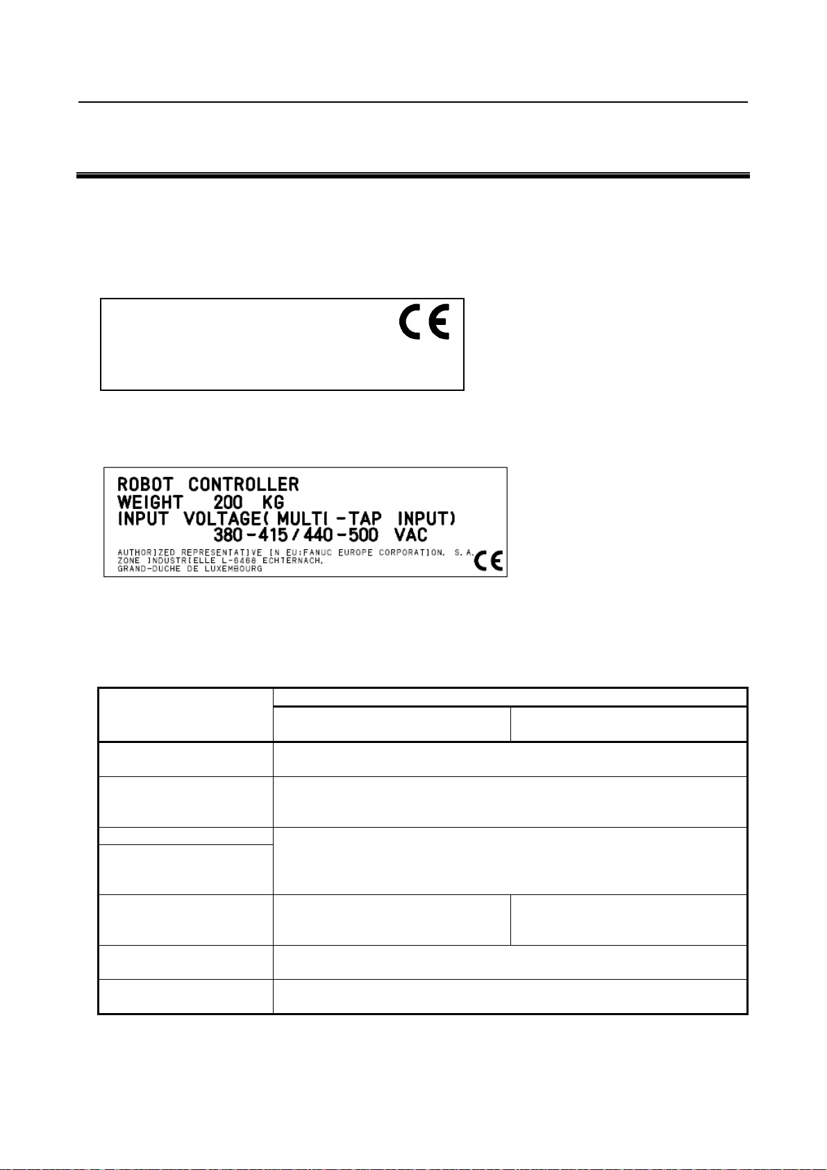
7. EU DECLARATION OF CONFORMITY B-80687EN/15
7 EU DECLARATION OF CONFORMITY
For FANUC robot series (for CE marking : both of the following labels are attached), EC declarations of
conformity with the following contents are applied.
Label for CE marking
(on the robot mechanical unit)
INDUSTRIAL ROBOT
工业机器人
AUTHORIZED REPRESENTATIVE IN EU :
FANUC Europe Corporation, S.A.
ZONE INDUSTRIELLE L-6468 ECHTERNACH,
GRAND-DUCHE DE LUXEMBOURG
Label for CE marking
(on the robot controller)
欧盟授权代表
*NOTE:
Value of "WEIGHT" and "INPUT
VOLTAGE" depend on the robot
controller specification.
Contents of
EC declarations of conformity
for Machinery Directive
(2006/42/EC)
Contents
Item
Name of
the manufacturer
Address of
the manufacturer
Model Please refer to "operator's manual" for each robot models.
Designation
Applied standards EN ISO 10218-1:2011
Importer/Distributor
in EU
Date Date of manufacture
FANUC CORPORATION
3580 Komanba, Shibokusa
Oshino-mura, Minamitsuru-gun
Yamanashi Prefecture, 401-0597 Japan
At the beginning of "PREFACE", following information is listed.
Model : "Model name"
Designation : "Mechanical unit specification No."
EN 60204-1:2006+A1
FANUC EUROPE CORPORATION
7, rue Benedikt Zender L-6468 Echternach
(to be written in EC declaration of conformity attached for each robot system)
Machinery Directive
(2006/42/EC)
EMC Directive (2014/30/EU)
Low Voltage Directive (2014/35/EU)
EN 55011:2009+A1 (2014/30/EU)
EN 61000-6-2:2005 (2014/30/EU)
EN 60204-1:2006+A1 (2014/35/EU)
- 40 -
Page 47

B-80687EN/15 8. CONTACTS
8 CONTACTS
ADDRESS PHONE
FANUC Corporation Oshino-mura, Yamanashi Prefecture 401-0597,
Japan
FANUC America Corporation.
Headquarters
FANUC America Corporation
Southeast Robotics Office
FANUC America Corporation
Midwest Robotics Office
FANUC America Corporation
Central/Northeast Robotics Office
FANUC America Corporation
West Robotics Office
Fanuc South America Equipamentos
de Automação e Serviços Ltda.
FANUC Canada, Ltd. 6774 Financial Drive
FANUC du Canada, Ltee. Succursale du Quebec 1096 Rue Levis,Suite #6
FANUC Mexico, S.A. de C.V. Circuito Aguascalientes Norte 136
FANUC America Corporation
Georgia Service Center
FANUC America Corporation
Massachusetts Service Center,
FANUC America Corporation
Minnesota Service Center,
FANUC America Corporation
New Jersey Service Center,
FANUC America Corporation
Ohio Service Center,
FANUC America Corporation
Texas Service Center,
FANUC America Corporation
Washington Service Center,
ANUC Europe Corporation 7, rue Benedikt Zender
FANUC Deutschland GmbH Bernhäuser Str. 36
FANUC France rue Léonard de Vinci
FANUC UK Limited Sapphire Way
FANUC Italia S.r.l. Viale delle Industrie 1/A
3900 W. Hamlin Road Rochester Hills,
Michigan 48309-3253
13245 Reese Blvd.#140 Campbell Building
Huntersville, NC 28078
1800 Lakewood Blvd.
Hoffman Estates, IL 60192
7700 Innovation Way
Mason, OH 45040
25951 Commercentre Drive
Lake Forest, CA 92630
Rua Matteo Forte, 22- Áqua Branca São Paulo,
SP Brasil CEP 05038-160
Mississauga, Ontario L5N 7J6
Lachenaie, Quebec J6W 4L1
Parque Industrial del Valle de Aguascalientes
20355 Aguascalientes, Ags. Mexico
2171 New Market Pkwy, Marietta, GA 30067
30 Boynton Road, Holliston, MA 01746
11545 Lakeland Dr. North,
Maple Grove, MN 55369
27 Bloomfield Avenue, Pine Brook, NJ 07058
2305 E. Aurora Rd., Twinsburg, OH 44087
3423 N. Sam Houston Parkway W., Suite 300,
Houston TX 77086
301 30th Streeet NE, Suite 100 - Building A,
Auburn, WA 98002
6468 Echternach
Luxembourg
73765 Neuhausen a.d.F.
Germany
91090 Lisses
France
Ansty Business Park
Coventry CV7 9DR
United Kingdom
20020 Arese (MI)
Italy
TEL:81-555-84-5555
FAX:81-555-84-5512
TEL:01-248-377-7000
TOLLFREE:01-800-47ROBOT (76268)
FAX: 01-248-276-4133
TEL: 01-704-597-6300
FAX: 01-704-596-2253
TEL:01-847-898-6000
FAX: 01-847- 898-6010
TEL:01-513-754-2400
FAX: 01-513-754-2440
TEL:01-949-59 5-2700
FAX:01-949-595-2750
TEL: 55-11-3619-0599
TEL: 01-905-812-2300
TEL: 01-450 492-9001
TEL:52-449-922-8000
TEL:01-888-326-8287
prompt 1 for Robotics
TEL:01-888-326-8287
prompt 1 for Robotics
TEL:01-888-326-8287
prompt 1 for Robotics
TEL:01-888-326-8287
prompt 1 for Robotics
TEL:01-888-326-8287
prompt 1 for Robotics
TEL:01-888-326-8287
prompt 1 for Robotics
TEL:01-888-326-8287
prompt 1 for Robotics
TEL: +352 72 7777 0
FAX: +352 72 7777 353
TEL: +49 7158 1282 0
FAX: +49 7158 1282 10
TEL: +33 1 6989 7000
FAX: +33 1 6989 7001
TEL: +44 24 7663 9669
FAX: +44 24 7630 4333
TEL: +39 02 4579 51
FAX: +39 02 4579 5250
- 41 -
Page 48

8. CONTACTS B-80687EN/15
ADDRESS PHONE
FANUC Iberia S.L.U. Poligono Industrial El Camí Ral
Ronda Can Rabada 23,
08860 Castelldefels
Spain
FANUC Czech s.r.o. U Pekařky 1A/484 (Budova B)
18000 Praha 8 - Libeň
Czech Republic
FANUC Slovakia s.r.o. Pri Jelsine 3636/1
949 01 Nitra
Slovakia
FANUC SWITZERLAND GMBH Grenchenstrasse 7
2500 Biel/Bienne
Switzerland
FANUC Benelux BVBA Generaal De Wittelaan 15
2800 Mechelen
Belgium
FANUC Hungary Kft. Torbágy utca 20
2045 Törökbálint
Hungary
FANUC Polska Sp. z o.o. ul. Tadeusza Wendy 2
52-407 Wrocław
Poland
FANUC Österreich GmbH Josef-Haas-Str. 9A
4655 Vorchdorf
Austria
FANUC LLC Nauchniy Proezd 19
117246 Moscow
Russia
Limited Liability Company "FANUC
UKRAINE"
FANUC Turkey Endüstriyel Otomasyon
Ticaret Limited Sirketi
FANUC Nordic AB P.O. Box 44
FANUC Automation Romania S.R.L. Ferma 9, Hala 25
FANUC Bulgaria EOOD ulitsa Okolovrasten pat 467
FANUC Adria d.o.o. Ipavčeva 21
SHANGHAI-FANUC Robotics Co., Ltd. No.1500 Fulian Road, Baoshan Area, Shanghai
KOREA FANUC CORPORATION 101 Wanam-ro, Seongsan-gu,
FANUC OCEANIA PTY LTD 10 Healey Circuit, Huntingwood, NSW 2148,
Stolychne hwy 100
03680 Kyiv
Ukraine
Şerifali Mah. Turgut Özal Bulvarı Sok. 190-192
34760 Ümraniye, Istanbul
Turkey
19124 Sollentuna
Sweden
407280 Florești
Romania
1588 Sofia
Bulgari
3000 Celje
Slovenia
P.R. China. Post Code: 201906
Changwon-si, Gyeongsangnam-do, Korea
Australia
TEL: +34 902 13 35 35
FAX: +34 902 12 35 36
TEL: +420 234 072 900
FAX: +420 234 072 110
TEL: +420 234 072 905
TEL: +41 323 66 63 63
FAX: +41 323 66 63 64
TEL: +32 1520 7157
FAX: +32 1520 7192
TEL: +36 23 332 007
FAX: +36 23 332 008
TEL: +48 71 7766 160
FAX: +48 71 7766 179
TEL: +43 732 77 4900
Fax: +43 761 45 2068
TEL: +7 495 66500 58
FAX: +7 495 22834 04
TEL: +380 44 531 55 50
FAX: +380 67 243 95 301
TEL: +90 444 9 362
FAX: +90 216 651 1405
TEL: +46 8 505 80 700
FAX: +46 8 505 80 701
TEL: +40747232682
TEL: +359 2 963 32 86
TEL: +386 8 205 64 97
FAX: +386 8 205 64 98
TEL: +86 21 5032 7700
FAX: +86 21 5032 7711
TEL: +82 55 278 1200
FAX: +82 55 284 9826
TEL: +61 2 8822 4600
FAX: +61 2 8822 4666
- 42 -
Page 49

B-80687EN/15 INDEX
INDEX
PROGRAMMING ......................................................... 33
<A>
AUTOMATIC OPERATION ........................................ 35
<C>
COMMISSIONING AND FUNCTIONAL
TESTING ................................................................... 31
CONFIGURATION OF ROBOT SYSTEM .................... 3
CONTACTS ................................................................... 41
CONTROL UNIT .......................................................... 39
PURPOSE OF ROBOT .................................................... 3
<R>
RELEVANT STANDARDS ............................................ 5
Restriction of Personnel ................................................. 31
Returning to Automatic Operation ................................. 33
ROBOT SYSTEM DESIGN ............................................ 6
Robot System Restart Procedures .................................. 31
Robot Training Items ....................................................... 4
<D>
DAILY MAINTENANCE ............................................. 39
DEADMAN SWITCH ................................................... 24
DEFINITION OF USER .................................................. 1
Designation of the Restricted Space ............................... 31
DISMANTLING / SCRAPPING ................................... 38
During Programming ...................................................... 33
<E>
EMERGENCY STOP .................................................... 22
END EFFECTOR, WORKPIECE AND
PERIPHERAL EQUIPMENT .................................... 11
EU DECLARATION OF CONFORMITY .................... 40
<F>
FANUC ROBOT SYSTEM ............................................. 3
<G>
GENERAL ....................................................................... 6
GENERAL CAUTIONS ................................................ 30
<I>
INSTALLATION ........................................................... 30
<M>
MAINTENANCE .......................................................... 35
MECHANICAL UNIT ................................................... 39
MODE SELECT SWITCH ............................................ 23
<S>
SAFEGUARDS ............................................................. 25
Safety and Operational Verification ............................... 31
SAFETY DEVICES ....................................................... 12
Safety Fence ................................................................... 25
Safety Gate and Plugs .................................................... 26
SAFETY OF THE MAINTENANCE
ENGINEER ................................................................ 36
SAFETY PRECAUTIONS .............................................. 1
SAFETY PROCEDURES FOR ENTERING
THE SAFETY FENCE .............................................. 28
STOP TYPE OF ROBOT (R-30iB Plus,
R-30iB Mate Plus, R-30iB Compact Plus) ................. 18
STOP TYPE OF ROBOT (R-30iA, R-30iA
Mate) .......................................................................... 12
STOP TYPE OF ROBOT (R-30iB, R-30iB
Mate) .......................................................................... 14
STORING PROGRAMMED DATA ............................. 34
<T>
TROUBLESHOOTING ................................................. 34
<O>
Operating Modes ............................................................ 23
OPERATION INSIDE OF THE SAFETY
FENCE ....................................................................... 27
OTHER CAUTIONS ..................................................... 38
OTHER PRECAUTIONS ................................................ 9
Other Protection Devices ............................................... 26
<P>
PLACEMENT OF EQUIPMENT .................................... 6
POWER SUPPLY AND PROTECTIVE
EARTH CONNECTION .............................................. 9
PRECAUTIONS FOR MECHANISM........................... 32
PREFACE .................................................................... p-1
Prior to Programming ..................................................... 33
PROGRAM VERIFICATION ....................................... 34
i-1
Page 50

Page 51

B-80687EN/15 REVISION RECORD
Edition
Date
Contents
• Correction of errors
• Correction of errors
• Correction of errors
12
Sep., 2014
• Additional description of definition of CAUTION and WARNING
11
Aug., 2014
• Additional description of CAUTION and WARNING
10
Dec., 2012
• Additional description of R-30iB Mate controller
09
Mar., 2012
• Additional description for N orth America NRTL compliance and R-30iB controller
08
Sep., 2010
• Applied to New Machinery Directive 2006/42/EC Rev i ew of all
07
Sep., 2009
• Applied to 2006/42/EC
06
Nov., 2008
• Additional descriptions f or North America NRTL compliance
05
Jan., 2008
• Applied to EN ISO10218
04
Oct., 2005
• All pages are changed.
03
Apr., 2001
• Additional descriptions for R-J3i MODEL B Controller.
02
Jul., 1996
• Additional descriptions of B-cabinet.
01
Feb., 1995
REVISION RECORD
• Addition of 1 SAFETY PRECAUTIONS
15 Jan., 2018
• Additional description of R-30iB Compact Plus controller
14 May,2017
13 Aug., 2016
• Additional description of R-30iB Plus, R-30iB Mate Plus controller
• Applied to new European EMC directive (2014/30/EU), new low voltage directive, and
review
r-1
Page 52

B-80687EN/15
*B-80687EN/ 15*
 Loading...