

Page 1

FANUC Robotics
R-J3iBMate Controller
(RIA R15.06 – 1999 Compliant)
Maintenance Manual
MARMIBRIA01021E REV. B
B-81535EN/02
This publication contains proprietary information of FANUC Robotics
North America, Inc. furnished for customer use only. No other uses
are authorized without the express written permission of FANUC
Robotics North America, Inc.
FANUC Robotics North America, Inc.
3900 W. Hamlin Road
Rochester Hills, Michigan 48309–3253
Page 2

The descriptions and specifications contained in this manual were in
effect at the time this manual was approved for printing. FANUC
Robotics North America, Inc, hereinafter referred to as FANUC
Robotics, reserves the right to discontinue models at any time or to
change specifications or design without notice and without incurring
obligations.
FANUC Robotics manuals present descriptions, specifications,
drawings, schematics, bills of material, parts, connections and/or
procedures for installing, disassembling, connecting, operating and
programming FANUC Robotics’ products and/or systems. Such
systems consist of robots, extended axes, robot controllers,
application software, the KAREL programming language,
INSIGHT vision equipment, and special tools.
FANUC Robotics recommends that only persons who have been
trained in one or more approved FANUC Robotics Training
Course(s) be permitted to install, operate, use, perform procedures
on, repair, and/or maintain FANUC Robotics’ products and/or
systems and their respective components. Approved training
necessitates that the courses selected be relevant to the type of
system installed and application performed at the customer site.
WARNING
This equipment generates, uses, and can radiate radio
frequency energy and if not installed and used in accordance
with the instruction manual, may cause interference to radio
communications. As temporarily permitted by regulation, it
has not been tested for compliance with the limits for Class A
computing devices pursuant to subpart J of Part 15 of FCC
Rules, which are designed to provide reasonable protection
against such interference. Operation of the equipment in a
residential area is likely to cause interference, in which case
the user, at his own expense, will be required to take
whatever measure may be required to correct the
interference.
FANUC Robotics conducts courses on its systems and products on
a regularly scheduled basis at its headquarters in Rochester Hills,
Michigan. For additional information contact
FANUC Robotics North America, Inc.
Training Department
3900 W. Hamlin Road
Rochester Hills, Michigan 48309-3253
www.fanucrobotics.com
Send your comments and suggestions about this manual to:
product.documentation@fanucrobotics.com
Page 3

Conventions
Copyright 2002 by FANUC Robotics North America, Inc.
All Rights Reserved
The information illustrated or contained herein is not to be
reproduced, copied, translated into another language, or transmitted
in whole or in part in any way without the prior written consent of
FANUC Robotics North America, Inc.
AccuStat, ArcTool, DispenseTool, FANUC LASER DRILL,
KAREL, INSIGHT, INSIGHT II, PaintTool, PaintWorks,
PalletTool, SOCKETS, SOFT PARTS SpotTool,
TorchMate, and YagTool are Registered Trademarks of FANUC
Robotics.
FANUC Robotics reserves all proprietary rights, including but not
limited to trademark and trade name rights, in the following names:
AccuAir AccuCal AccuChop AccuFlow AccuPath
AccuSeal ARC Mate ARC Mate Sr. ARC Mate System 1
ARC Mate System 2 ARC Mate System 3 ARC Mate System
4 ARC Mate System 5 ARCWorks Pro AssistTool
AutoNormal AutoTCP BellTool BODYWorks Cal Mate Cell
Finder Center Finder Clean Wall CollisionGuard
DispenseTool F-100 F-200i FabTool FANUC LASER
DRILL Flexibell FlexTool HandlingTool HandlingWorks
INSIGHT INSIGHT II IntelliTrak Integrated Process Solution
Intelligent Assist Device IPC -Integrated Pump Control IPD
Integral Pneumatic Dispenser ISA Integral Servo Applicator ISD
Integral Servo Dispenser Laser Mate System 3 Laser Mate
System 4 LaserPro LaserTool LR Tool MIG Eye
MotionParts NoBots Paint Stick PaintPro PaintTool 100
PAINTWorks PAINTWorks II PAINTWorks III PalletMate
PalletMate PC PalletTool PC PayloadID RecipTool
RemovalTool Robo Chop Robo Spray S-420i S-430i
ShapeGen SoftFloat SOF PARTS SpotTool+ SR Mate
SR ShotTool SureWeld SYSTEM R-J2 Controller SYSTEM RJ3 Controller SYSTEM R-J3iB Controller TCP Mate
TurboMove TorchMate visLOC visPRO-3D visTRAC
WebServer WebTP YagTool
This manual includes information essential to the safety of
personnel, equipment, software, and data. This information is
indicated by headings and boxes in the text.
WARNING
Information appearing under WARNING concerns the
protection of personnel. It is boxed and in bold type to set it
apart from other text.
Page 4

CAUTION
Information appearing under CAUTION concerns the protection of
equipment, software, and data. It is boxed to set it apart from
other text.
NOTE Information appearing next to NOTE concerns related information
or useful hints.
Page 5

Safety
Safety-1
FANUC Robotics is not and does not represent itself as an expert in
safety systems, safety equipment, or the specific safety aspects of
your company and/or its work force. It is the responsibility of the
owner, employer, or user to take all necessary steps to guarantee
the safety of all personnel in the workplace.
The appropriate level of safety for your application and installation
can best be determined by safety system professionals. FANUC
Robotics therefore, recommends that each customer consult with
such professionals in order to provide a workplace that allows for
the safe application, use, and operation of FANUC Robotic systems.
According to the industry standard ANSI/RIA R15.06, the owner or
user is advised to consult the standards to ensure compliance with
its requests for Robotics System design, usability, operation,
maintenance, and service. Additionally, as the owner, employer, or
user of a robotic system, it is your responsibility to arrange for the
training of the operator of a robot system to recognize and respond
to known hazards associated with your robotic system and to be
aware of the recommended operating procedures for your particular
application and robot installation.
FANUC Robotics therefore, recommends that all personnel who
intend to operate, program, repair, or otherwise use the robotics
system be trained in an approved FANUC Robotics training course
and become familiar with the proper operation of the system.
Persons responsible for programming the system–including the
design, implementation, and debugging of application programs–
must be familiar with the recommended programming procedures
for your application and robot installation.
The following guidelines are provided to emphasize the importance
of safety in the workplace.
Page 6

Safety-2
y
CONSIDERING
SAFETY FOR YOUR
ROBOT
INSTALLATION
Keeping People and
Equipment Safe
Using Safet
Enhancing Devices
Safety is essential whenever robots are used. Keep in mind the
following factors with regard to safety:
• The safety of people and equipment
• Use of safety enhancing devices
• Techniques for safe teaching and manual operation of the
robot(s)
• Techniques for safe automatic operation of the robot(s)
• Regular scheduled inspection of the robot and workcell
• Proper maintenance of the robot
The safety of people is always of primary importance in any
situation. However, equipment must be kept safe, too. When
prioritizing how to apply safety to your robotic system, consider the
following:
• People
• External devices
• Robot(s)
• Tooling
• Workpiece
Always give appropriate attention to the work area that surrounds
the robot. The safety of the work area can be enhanced by the
installation of some or all of the following devices:
• Safety fences, barriers, or chains
• Light curtains
• Interlocks
• Pressure mats
• Floor markings
• Warning lights
• Mechanical stops
• EMERGENCY STOP buttons
• DEADMAN switches
Setting Up a Safe
Workcell
A safe workcell is essential to protect people and equipment.
Observe the following guidelines to ensure that the workcell is set
up safely. These suggestions are intended to supplement and not
replace existing federal, state, and local laws, regulations, and
guidelines that pertain to safety.
• Sponsor your personnel for training in approved FANUC
Robotics training course(s) related to your application. Never
permit untrained personnel to operate the robots.
Page 7

Safety-3
• Install a lockout device that uses an access code to prevent
unauthorized persons from operating the robot.
• Use anti–tie–down logic to prevent the operator from bypassing
safety measures.
• Arrange the workcell so the operator faces the workcell and can
see what is going on inside the cell.
• Clearly identify the work envelope of each robot in the system
with floor markings, signs, and special barriers. The work
envelope is the area defined by the maximum motion range of
the robot, including any tooling attached to the wrist flange that
extend this range.
• Position all controllers outside the robot work envelope.
• Never rely on software as the primary safety element.
• Mount an adequate number of EMERGENCY STOP buttons or
switches within easy reach of the operator and at critical points
inside and around the outside of the workcell.
• Install flashing lights and/or audible warning devices that
activate whenever the robot is operating, that is, whenever
power is applied to the servo drive system. Audible warning
devices shall exceed the ambient noise level at the end–use
application.
• Wherever possible, install safety fences to protect against
unauthorized entry by personnel into the work envelope.
• Install special guarding that prevents the operator from reaching
into restricted areas of the work envelope.
• Use interlocks.
• Use presence or proximity sensing devices such as light
curtains, mats, and capacitance and vision systems to enhance
safety.
• Periodically check the safety joints or safety clutches that can be
optionally installed between the robot wrist flange and tooling. If
the tooling strikes an object, these devices dislodge, remove
power from the system, and help to minimize damage to the
tooling and robot.
Page 8

Safety-4
• Make sure all external devices are properly filtered, grounded,
shielded, and suppressed to prevent hazardous motion due to
the effects of electro–magnetic interference (EMI), radio
frequency interference (RFI), and electro–static discharge
(ESD).
• Make provisions for power lockout/tagout at the controller.
• Eliminate pinch points. Pinch points are areas where personnel
could get trapped between a moving robot and other equipment.
• Provide enough room inside the workcell to permit personnel to
teach the robot and perform maintenance safely.
• Program the robot to load and unload material safely.
• If high voltage electrostatics are present, be sure to provide
appropriate interlocks, warning, and beacons.
• If materials are being applied at dangerously high pressure,
provide electrical interlocks for lockout of material flow and
pressure.
Staying Safe While
Teaching or Manually
Operating the Robot
Advise all personnel who must teach the robot or otherwise
manually operate the robot to observe the following rules:
• Never wear watches, rings, neckties, scarves, or loose clothing
that could get caught in moving machinery.
• Know whether or not you are using an intrinsically safe teach
pendant if you are working in a hazardous environment.
• Before teaching, visually inspect the robot and work envelope to
make sure that no potentially hazardous conditions exist. The
work envelope is the area defined by the maximum motion
range of the robot. These include tooling attached to the wrist
flange that extends this range.
• The area near the robot must be clean and free of oil, water, or
debris. Immediately report unsafe working conditions to the
supervisor or safety department.
• FANUC Robotics recommends that no one enter the work
envelope of a robot that is on, except for robot teaching
operations. However, if you must enter the work envelope, be
sure all safeguards are in place, check the teach pendant
DEADMAN switch for proper operation, and place the robot in
teach mode. Take the teach pendant with you, turn it on, and be
prepared to release the DEADMAN switch. Only the person
with the teach pendant should be in the work envelope.
Page 9
Safety-5
WARNING
Never bypass, strap, or otherwise deactivate a safety device,
such as a limit switch, for any operational convenience.
Deactivating a safety device is known to have resulted in
serious injury and death.
• Know the path that can be used to escape from a moving robot;
make sure the escape path is never blocked.
• Isolate the robot from all remote control signals that can cause
motion while data is being taught.
• Test any program being run for the first time in the following
manner:
WARNING
Stay outside the robot work envelope whenever a program is
being run. Failure to do so can result in injury.
Staying Safe During
Automatic Operation
- Using a low motion speed, single step the program for at
least one full cycle.
- Using a low motion speed, test run the program continuously
for at least one full cycle.
- Using the programmed speed, test run the program
continuously for at least one full cycle.
• Make sure all personnel are outside the work envelope before
running production.
Advise all personnel who operate the robot during production to
observe the following rules:
• Make sure all safety provisions are present and active.
• Know the entire workcell area. The workcell includes the robot
and its work envelope, plus the area occupied by all external
devices and other equipment with which the robot interacts.
• Understand the complete task the robot is programmed to
perform before initiating automatic operation.
• Make sure all personnel are outside the work envelope before
operating the robot.
Page 10

Safety-6
• Never enter or allow others to enter the work envelope during
automatic operation of the robot.
• Know the location and status of all switches, sensors, and
control signals that could cause the robot to move.
• Know where the EMERGENCY STOP buttons are located on
both the robot control and external control devices. Be prepared
to press these buttons in an emergency.
• Never assume that a program is complete if the robot is not
moving. The robot could be waiting for an input signal that will
permit it to continue activity.
• If the robot is running in a pattern, do not assume it will continue
to run in the same pattern.
• Never try to stop the robot, or break its motion, with your body.
The only way to stop robot motion immediately is to press an
EMERGENCY STOP button located on the controller panel,
teach pendant, or emergency stop stations around the workcell.
Staying Safe During
Inspection
When inspecting the robot, be sure to
• Turn off power at the controller.
• Lock out and tag out the power source at the controller
according to the policies of your plant.
• Turn off the compressed air source and relieve the air pressure.
• If robot motion is not needed for inspecting the electrical circuits,
press the EMERGENCY STOP button on the operator panel.
• Never wear watches, rings, neckties, scarves, or loose clothing
that could get caught in moving machinery.
• If power is needed to check the robot motion or electrical
circuits, be prepared to press the EMERGENCY STOP button,
in an emergency.
• Be aware that when you remove a servomotor or brake, the
associated robot arm will fall if it is not supported or resting on a
hard stop. Support the arm on a solid support before you
release the brake.
Staying Safe During
Maintenance
When performing maintenance on your robot system, observe the
following rules:
Page 11
Safety-7
• Never enter the work envelope while the robot or a program is in
operation.
• Before entering the work envelope, visually inspect the workcell
to make sure no potentially hazardous conditions exist.
• Never wear watches, rings, neckties, scarves, or loose clothing
that could get caught in moving machinery.
• Consider all or any overlapping work envelopes of adjoining
robots when standing in a work envelope.
• Test the teach pendant for proper operation before entering the
work envelope.
• If it is necessary for you to enter the robot work envelope while
power is turned on, you must be sure that you are in control of
the robot. Be sure to take the teach pendant with you, press the
DEADMAN switch, and turn the teach pendant on. Be prepared
to release the DEADMAN switch to turn off servo power to the
robot immediately.
• Whenever possible, perform maintenance with the power turned
off. Before you open the controller front panel or enter the work
envelope, turn off and lock out the 3–phase power source at the
controller.
• Be aware that when you remove a servomotor or brake, the
associated robot arm will fall if it is not supported or resting on a
hard stop. Support the arm on a solid support before you
release the brake.
WARNING
Lethal voltage is present in the controller WHENEVER IT IS
CONNECTED to a power source. Be extremely careful to
avoid electrical shock.
HIGH VOLTAGE IS PRESENT at the input side whenever the
controller is connected to a power source. Turning the
disconnect or circuit breaker to the OFF position removes
power from the output side of the device only.
• Release or block all stored energy. Before working on the
pneumatic system, shut off the system air supply and purge the
air lines.
Page 12
Safety-8
• Isolate the robot from all remote control signals. If maintenance
must be done when the power is on, make sure the person
inside the work envelope has sole control of the robot. The
teach pendant must be held by this person.
• Make sure personnel cannot get trapped between the moving
robot and other equipment. Know the path that can be used to
escape from a moving robot. Make sure the escape route is
never blocked.
• Use blocks, mechanical stops, and pins to prevent hazardous
movement by the robot. Make sure that such devices do not
create pinch points that could trap personnel.
WARNING
Do not try to remove any mechanical component from the
robot before thoroughly reading and understanding the
procedures in the appropriate manual. Doing so can result in
serious personal injury and component destruction.
KEEPING MACHINE
TOOLS AND
EXTERNAL
DEVICES SAFE
• Be aware that when you remove a servomotor or brake, the
associated robot arm will fall if it is not supported or resting on a
hard stop. Support the arm on a solid support before you
release the brake.
• When replacing or installing components, make sure dirt and
debris do not enter the system.
• Use only specified parts for replacement. To avoid fires and
damage to parts in the controller, never use nonspecified fuses.
• Before restarting a robot, make sure no one is inside the work
envelope; be sure that the robot and all external devices are
operating normally.
Certain programming and mechanical measures are useful in
keeping the machine tools and other external devices safe. Some
of these measures are outlined below. Make sure you know all
associated measures for safe use of such devices.
Programming Safety
Precautions
Implement the following programming safety measures to prevent
damage to machine tools and other external devices.
Page 13

Mechanical Safety
Precautions
Safety-9
• Back–check limit switches in the workcell to make sure they do
not fail.
• Implement ‘‘failure routines” in programs that will provide
appropriate robot actions if an external device or another robot
in the workcell fails.
• Use handshaking protocol to synchronize robot and external
device operations.
• Program the robot to check the condition of all external devices
during an operating cycle.
Implement the following mechanical safety measures to prevent
damage to machine tools and other external devices.
• Make sure the workcell is clean and free of oil, water, and
debris.
• Use software limits, limit switches, and mechanical hardstops to
prevent undesired movement of the robot into the work area of
machine tools and external devices.
KEEPING THE
ROBOT SAFE
Operating Safety
Precautions
Programming Safety
Precautions
Observe the following operating and programming guidelines to
prevent damage to the robot.
The following measures are designed to prevent damage to the
robot during operation.
• Use a low override speed to increase your control over the robot
when jogging the robot.
• Visualize the movement the robot will make before you press
the jog keys on the teach pendant.
• Make sure the work envelope is clean and free of oil, water, or
debris.
• Use circuit breakers to guard against electrical overload.
The following safety measures are designed to prevent damage to
the robot during programming:
• Establish interference zones to prevent collisions when two or
more robots share a work area.
Page 14

Safety-10
• Make sure that the program ends with the robot near or at the
home position.
• Be aware of signals or other operations that could trigger
operation of tooling resulting in personal injury or equipment
damage.
• In dispensing applications, be aware of all safety guidelines with
respect to the dispensing materials.
NOTE Any deviation from the methods and safety practices
described in this manual must conform to the approved standards of
your company. If you have questions, see your supervisor.
ADDITIONAL
SAFETY
CONSIDERATIONS
FOR PAINT ROBOT
INSTALLATIONS
Process technicians are sometimes required to enter the paint
booth, for example, during daily or routine calibration or while
teaching new paths to a robot. Maintenance personal also must
work inside the paint booth periodically.
Whenever personnel are working inside the paint booth, ventilation
equipment must be used. Instruction on the proper use of
ventilating equipment usually is provided by the paint shop
supervisor.
Although paint booth hazards have been minimized, potential
dangers still exist. Therefore, today’s highly automated paint booth
requires that process and maintenance personnel have full
awareness of the system and its capabilities. They must
understand the interaction that occurs between the vehicle moving
along the conveyor and the robot(s), hood/deck and door opening
devices, and high–voltage electrostatic tools.
Paint robots are operated in three modes:
• Teach or manual mode
• Automatic mode, including automatic and exercise operation
• Diagnostic mode
During both teach and automatic modes, the robots in the paint
booth will follow a predetermined pattern of movements. In teach
mode, the process technician teaches (programs) paint paths using
the teach pendant.
In automatic mode, robot operation is initiated at the System
Operator Console (SOC) or Manual Control Panel (MCP), if
available, and can be monitored from outside the paint booth. All
personnel must remain outside of the booth or in a designated safe
Page 15

Safety-11
area within the booth whenever automatic mode is initiated at the
SOC or MCP.
In automatic mode, the robots will execute the path movements they
were taught during teach mode, but generally at production speeds.
When process and maintenance personnel run diagnostic routines
that require them to remain in the paint booth, they must stay in a
designated safe area.
Paint System Safety
Features
Process technicians and maintenance personnel must become
totally familiar with the equipment and its capabilities. To minimize
the risk of injury when working near robots and related equipment,
personnel must comply strictly with the procedures in the manuals.
This section provides information about the safety features that are
included in the paint system and also explains the way the robot
interacts with other equipment in the system.
The paint system includes the following safety features:
• Most paint booths have red warning beacons that illuminate
when the robots are armed and ready to paint. Your booth
might have other kinds of indicators. Learn what these are.
• Some paint booths have a blue beacon that, when illuminated,
indicates that the electrostatic devices are enabled. Your booth
might have other kinds of indicators. Learn what these are.
• EMERGENCY STOP buttons are located on the robot controller
and teach pendant. Become familiar with the locations of all E–
STOP buttons.
• An intrinsically safe teach pendant is used when teaching in
hazardous paint atmospheres.
• A DEADMAN switch is located on each teach pendant. When this
switch is held in, and the teach pendant is on, power is applied to the
robot servo system. If the engaged DEADMAN switch is released
during robot operation, power is removed from the servo system, all
axis brakes are applied, and the robot comes to an EMERGENCY
STOP. Safety interlocks within the system might also E–STOP other
robots.
WARNING
An EMERGENCY STOP will occur if the DEADMAN switch is
released on a bypassed robot.
Page 16
Safety-12
• Overtravel by robot axes is prevented by software limits. All of
the major and minor axes are governed by software limits. Limit
switches and hardstops also limit travel by the major axes.
• EMERGENCY STOP limit switches and photoelectric eyes
might be part of your system. Limit switches, located on the
entrance/exit doors of each booth, will EMERGENCY STOP all
equipment in the booth if a door is opened while the system is
operating in automatic or manual mode. For some systems,
signals to these switches are inactive when the switch on the
SCC is in teach mode.
When present, photoelectric eyes are sometimes used to
monitor unauthorized intrusion through the entrance/exit
silhouette openings.
• System status is monitored by computer. Severe conditions
result in automatic system shutdown.
Staying Safe While
Operating the Paint
Robot
When you work in or near the paint booth, observe the following
rules, in addition to all rules for safe operation that apply to all robot
systems.
WARNING
Observe all safety rules and guidelines to avoid injury.
WARNING
Never bypass, strap, or otherwise deactivate a safety device,
such as a limit switch, for any operational convenience.
Deactivating a safety device is known to have resulted in
serious injury and death.
• Know the work area of the entire paint station (workcell).
• Know the work envelope of the robot and hood/deck and door
opening devices.
• Be aware of overlapping work envelopes of adjacent robots.
• Know where all red, mushroom–shaped EMERGENCY STOP
buttons are located.
Page 17

Safety-13
• Know the location and status of all switches, sensors, and/or
control signals that might cause the robot, conveyor, and
opening devices to move.
• Make sure that the work area near the robot is clean and free of
water, oil, and debris. Report unsafe conditions to your
supervisor.
• Become familiar with the complete task the robot will perform
BEFORE starting automatic mode.
• Make sure all personnel are outside the paint booth before you
turn on power to the robot servo system.
• Never enter the work envelope or paint booth before you turn off
power to the robot servo system.
• Never enter the work envelope during automatic operation
unless a safe area has been designated.
• Never wear watches, rings, neckties, scarves, or loose clothing
that could get caught in moving machinery.
Staying Safe While
Operating Paint
Application Equipment
• Remove all metallic objects, such as rings, watches, and belts,
before entering a booth when the electrostatic devices are
enabled.
• Stay out of areas where you might get trapped between a
moving robot, conveyor, or opening device and another object.
• Be aware of signals and/or operations that could result in the
triggering of guns or bells.
• Be aware of all safety precautions when dispensing of paint is
required.
• Follow the procedures described in this manual.
When you work with paint application equipment, observe the
following rules, in addition to all rules for safe operation that apply to
all robot systems.
WARNING
When working with electrostatic paint equipment, follow all
national and local codes as well as all safety guidelines
within your organization. Also reference the following
standards: NFPA 33 Standards for Spray Application Using
Flammable or Combustible Materials, and NFPA 70 National
Electrical Code.
Page 18

Safety-14
• Grounding: All electrically conductive objects in the spray area
must be grounded. This includes the spray booth, robots,
conveyors, workstations, part carriers, hooks, paint pressure
pots, as well as solvent containers. Grounding is defined as the
object or objects shall be electrically connected to ground with a
resistance of not more than 1 megohms.
• High Voltage: High voltage should only be on during actual
spray operations. Voltage should be off when the painting
process is completed. Never leave high voltage on during a cap
cleaning process.
• Avoid any accumulation of combustible vapors or coating
matter.
• Follow all manufacturer recommended cleaning procedures.
• Make sure all interlocks are operational.
• No smoking.
Staying Safe During
Maintenance
• Post all warning signs regarding the electrostatic equipment and
operation of electrostatic equipment according to NFPA 33
Standard for Spray Application Using Flammable or
Combustible Material.
• Disable all air and paint pressure to bell.
• Verify that the lines are not under pressure.
When you perform maintenance on the painter system, observe the
following rules, and all other maintenance safety rules that apply to
all robot installations. Only qualified, trained service or maintenance
personnel should perform repair work on a robot.
• Paint robots operate in a potentially explosive environment. Use
caution when working with electric tools.
• When a maintenance technician is repairing or adjusting a robot,
the work area is under the control of that technician. All
personnel not participating in the maintenance must stay out of
the area.
• For some maintenance procedures, station a second person at
the control panel within reach of the EMERGENCY STOP
button. This person must understand the robot and associated
potential hazards.
Page 19

Safety-15
• Be sure all covers and inspection plates are in good repair and
in place.
• Always return the robot to the ‘‘home’’ position before you
disarm it.
• Never use machine power to aid in removing any component
from the robot.
• During robot operations, be aware of the robot’s movements.
Excess vibration, unusual sounds, and so forth, can alert you to
potential problems.
• Whenever possible, turn off the main electrical disconnect
before you clean the robot.
• When using vinyl resin observe the following:
- Wear eye protection and protective gloves during application
and removal
- Adequate ventilation is required. Overexposure could cause
drowsiness or skin and eye irritation.
- If there is contact with the skin, wash with water.
• When using paint remover observe the following:
- Eye protection, protective rubber gloves, boots, and apron
are required during booth cleaning.
- Adequate ventilation is required. Overexposure could cause
drowsiness.
- If there is contact with the skin or eyes, rinse with water for
at least 15 minutes.
Page 20

Update Section
Single Phase Power Option
Page 21

Page 22

Page 23

Page 24

Page 25

Page 26
Page 27

B–81535EN/02
Table of Contents
PREFACE p–1. . . . . . . . . . . . . . . . . . . . . . . . . . . . . . . . . . . . . . . . . . . . . . . . . . . . . . . . . . . . . . . .
I SAFETY PRECAUTIONS
1. SAFETY PRECAUTIONS 3. . . . . . . . . . . . . . . . . . . . . . . . . . . . . . . . . . . . . . . . . . . . . . .
1.1 OPERATOR SAFETY 4. . . . . . . . . . . . . . . . . . . . . . . . . . . . . . . . . . . . . . . . . . . . . . . . . . . . . . . . . . . .
1.1.1 Operator Safety 6. . . . . . . . . . . . . . . . . . . . . . . . . . . . . . . . . . . . . . . . . . . . . . . . . . . . . . . . . . . . . . . . . . .
1.1.2 Safety of the T each Pendant Operator 7. . . . . . . . . . . . . . . . . . . . . . . . . . . . . . . . . . . . . . . . . . . . . . . . . .
1.1.3 Safety During Maintenance 9. . . . . . . . . . . . . . . . . . . . . . . . . . . . . . . . . . . . . . . . . . . . . . . . . . . . . . . . .
1.2 SAFETY OF THE TOOLS AND PERIPHERAL DEVICES 10. . . . . . . . . . . . . . . . . . . . . . . . . . . . . .
1.2.1 Precautions in Programming 10. . . . . . . . . . . . . . . . . . . . . . . . . . . . . . . . . . . . . . . . . . . . . . . . . . . . . . . . .
1.2.2 Precautions for Mechanism 10. . . . . . . . . . . . . . . . . . . . . . . . . . . . . . . . . . . . . . . . . . . . . . . . . . . . . . . . . .
1.3 SAFETY OF THE ROBOT MECHANISM 11. . . . . . . . . . . . . . . . . . . . . . . . . . . . . . . . . . . . . . . . . . . .
1.3.1 Precautions in Operation 11. . . . . . . . . . . . . . . . . . . . . . . . . . . . . . . . . . . . . . . . . . . . . . . . . . . . . . . . . . . .
1.3.2 Precautions in Programming 11. . . . . . . . . . . . . . . . . . . . . . . . . . . . . . . . . . . . . . . . . . . . . . . . . . . . . . . . .
1.3.3 Precautions for Mechanisms 11. . . . . . . . . . . . . . . . . . . . . . . . . . . . . . . . . . . . . . . . . . . . . . . . . . . . . . . . .
1.4 SAFETY OF THE END EFFECTOR 12. . . . . . . . . . . . . . . . . . . . . . . . . . . . . . . . . . . . . . . . . . . . . . . . .
1.4.1 Precautions in Programming 12. . . . . . . . . . . . . . . . . . . . . . . . . . . . . . . . . . . . . . . . . . . . . . . . . . . . . . . . .
1.5 SAFETY IN MAINTENANCE 13. . . . . . . . . . . . . . . . . . . . . . . . . . . . . . . . . . . . . . . . . . . . . . . . . . . . .
1.6 WARNING LABEL 14. . . . . . . . . . . . . . . . . . . . . . . . . . . . . . . . . . . . . . . . . . . . . . . . . . . . . . . . . . . . . .
II MAINTENANCE
1. OVERVIEW 19. . . . . . . . . . . . . . . . . . . . . . . . . . . . . . . . . . . . . . . . . . . . . . . . . . . . . . . . . . .
2. CONFIGURATION 20. . . . . . . . . . . . . . . . . . . . . . . . . . . . . . . . . . . . . . . . . . . . . . . . . . . . .
2.1 EXTERNAL VIEW OF THE CONTROLLER 21. . . . . . . . . . . . . . . . . . . . . . . . . . . . . . . . . . . . . . . . .
2.2 COMPONENT FUNCTIONS 23. . . . . . . . . . . . . . . . . . . . . . . . . . . . . . . . . . . . . . . . . . . . . . . . . . . . . . .
2.3 PREVENTIVE MAINTENANCE 24. . . . . . . . . . . . . . . . . . . . . . . . . . . . . . . . . . . . . . . . . . . . . . . . . . .
3. TROUBLESHOOTING 25. . . . . . . . . . . . . . . . . . . . . . . . . . . . . . . . . . . . . . . . . . . . . . . . . .
3.1 POWER CANNOT BE TURNED ON 26. . . . . . . . . . . . . . . . . . . . . . . . . . . . . . . . . . . . . . . . . . . . . . . .
3.1.1 T each Pendant Cannot be Turned On 27. . . . . . . . . . . . . . . . . . . . . . . . . . . . . . . . . . . . . . . . . . . . . . . . . .
3.1.2 Initial Screen Remains on the T each Pendant 28. . . . . . . . . . . . . . . . . . . . . . . . . . . . . . . . . . . . . . . . . . . .
3.2 ALARM OCCURRENCE SCREEN 29. . . . . . . . . . . . . . . . . . . . . . . . . . . . . . . . . . . . . . . . . . . . . . . . .
3.3 SAFETY SIGNALS 32. . . . . . . . . . . . . . . . . . . . . . . . . . . . . . . . . . . . . . . . . . . . . . . . . . . . . . . . . . . . . .
3.4 MASTERING 33. . . . . . . . . . . . . . . . . . . . . . . . . . . . . . . . . . . . . . . . . . . . . . . . . . . . . . . . . . . . . . . . . . .
3.5 TROUBLESHOOTING USING THE ERROR CODE 35. . . . . . . . . . . . . . . . . . . . . . . . . . . . . . . . . . .
3.6 TROUBLESHOOTING USING FUSES 92. . . . . . . . . . . . . . . . . . . . . . . . . . . . . . . . . . . . . . . . . . . . . .
3.7 TROUBLESHOOTING BASED ON LED INDICATIONS 97. . . . . . . . . . . . . . . . . . . . . . . . . . . . . . .
3.8 POSITION DEVIATION FOUND IN RETURN TO THE REFERENCE POSITION
(POSITIONING) 107. . . . . . . . . . . . . . . . . . . . . . . . . . . . . . . . . . . . . . . . . . . . . . . . . . . . . . . . . . . . . . . . .
3.9 VIBRATION OBSERVED DURING MOVEMENT 108. . . . . . . . . . . . . . . . . . . . . . . . . . . . . . . . . . . . .
3.10 MANUAL OPERATION IMPOSSIBLE 109. . . . . . . . . . . . . . . . . . . . . . . . . . . . . . . . . . . . . . . . . . . . . .
c–1
Page 28

Table of Contents
B–81535EN/02
4. PRINTED CIRCUIT BOARDS 1 11. . . . . . . . . . . . . . . . . . . . . . . . . . . . . . . . . . . . . . . . . . . .
4.1 ROBOT CONTROL BOARD (A16B–3200–0450) 112. . . . . . . . . . . . . . . . . . . . . . . . . . . . . . . . . . . . . .
4.2 EMERGENCY STOP BOARD (A20B–1008–0010, –0011) 116. . . . . . . . . . . . . . . . . . . . . . . . . . . . . . .
4.3 BACKPLANE BOARD (A20B–2003–0330) 117. . . . . . . . . . . . . . . . . . . . . . . . . . . . . . . . . . . . . . . . . . .
4.4 PROCESS I/O BOARD HE (A16B–2203–0764), HF (A16B–2203–0765) 118. . . . . . . . . . . . . . . . . . .
5. SERVO AMPLIFIERS 120. . . . . . . . . . . . . . . . . . . . . . . . . . . . . . . . . . . . . . . . . . . . . . . . . . .
5.1 OUTLINE DRAWINGS 121. . . . . . . . . . . . . . . . . . . . . . . . . . . . . . . . . . . . . . . . . . . . . . . . . . . . . . . . . . .
5.1.1 Power Supply Module PSM (A06B–6115–H001) 121. . . . . . . . . . . . . . . . . . . . . . . . . . . . . . . . . . . . . . . .
5.1.2 Servo Amplifier Module (A06B–6114–H205, A06B–6114–H302) 122. . . . . . . . . . . . . . . . . . . . . . . . . . .
5.2 LED OF SERVO AMPLIFIER 123. . . . . . . . . . . . . . . . . . . . . . . . . . . . . . . . . . . . . . . . . . . . . . . . . . . . . .
5.2.1 LED of Power Supply Module 123. . . . . . . . . . . . . . . . . . . . . . . . . . . . . . . . . . . . . . . . . . . . . . . . . . . . . . .
5.2.2 LED of Servo Amplifier Module 124. . . . . . . . . . . . . . . . . . . . . . . . . . . . . . . . . . . . . . . . . . . . . . . . . . . . .
6. SETTING THE POWER SUPPLY 125. . . . . . . . . . . . . . . . . . . . . . . . . . . . . . . . . . . . . . . . .
6.1 BLOCK DIAGRAMS OF THE POWER SUPPLY 126. . . . . . . . . . . . . . . . . . . . . . . . . . . . . . . . . . . . . .
6.2 CHECKING THE POWER SUPPLY UNIT 127. . . . . . . . . . . . . . . . . . . . . . . . . . . . . . . . . . . . . . . . . . .
6.3 CHECKING THE POWER SUPPLY MODULE 127. . . . . . . . . . . . . . . . . . . . . . . . . . . . . . . . . . . . . . . .
7. REPLACING A UNIT 128. . . . . . . . . . . . . . . . . . . . . . . . . . . . . . . . . . . . . . . . . . . . . . . . . . .
7.1 REPLACING THE PRINTED–CIRCUIT BOARDS 129. . . . . . . . . . . . . . . . . . . . . . . . . . . . . . . . . . . .
7.1.1 Replacing the Backplane Board (Unit) 130. . . . . . . . . . . . . . . . . . . . . . . . . . . . . . . . . . . . . . . . . . . . . . . . .
7.1.2 Replacing the Robot Control Board and Printed–Circuit Boards on the Backplane Unit 131. . . . . . . . . . .
7.1.3 Replacing the Emergency Stop Board 132. . . . . . . . . . . . . . . . . . . . . . . . . . . . . . . . . . . . . . . . . . . . . . . . .
7.2 REPLACING CARDS AND MODULES ON THE ROBOT CONTROL BOARD 133. . . . . . . . . . . . .
7.3 REPLACING THE TRANSFORMER 137. . . . . . . . . . . . . . . . . . . . . . . . . . . . . . . . . . . . . . . . . . . . . . . .
7.3.1 Replacing the Brake Power Transformer 137. . . . . . . . . . . . . . . . . . . . . . . . . . . . . . . . . . . . . . . . . . . . . . .
7.4 REPLACING THE EMERGENCY STOP UNIT 138. . . . . . . . . . . . . . . . . . . . . . . . . . . . . . . . . . . . . . .
7.5 REPLACING THE MAGNETIC CONTACTOR 139. . . . . . . . . . . . . . . . . . . . . . . . . . . . . . . . . . . . . . .
7.6 REPLACING SERVO AMPLIFIERS 140. . . . . . . . . . . . . . . . . . . . . . . . . . . . . . . . . . . . . . . . . . . . . . . .
7.7 REPLACING THE TEACH PENDANT 141. . . . . . . . . . . . . . . . . . . . . . . . . . . . . . . . . . . . . . . . . . . . . .
7.8 REPLACING THE CONTROL SECTION FAN MOTOR 142. . . . . . . . . . . . . . . . . . . . . . . . . . . . . . . .
7.9 REPLACING THE FAN MOTOR OF THE SERVO AMPLIFIER CONTROL UNIT 143. . . . . . . . . .
7.10 REPLACING THE DOOR FAN UNIT AND HEAT EXCHANGER 144. . . . . . . . . . . . . . . . . . . . . . . .
7.11 REPLACING THE OPERATOR PANEL 145. . . . . . . . . . . . . . . . . . . . . . . . . . . . . . . . . . . . . . . . . . . . .
7.12 REPLACING THE POWER SUPPLY UNIT 146. . . . . . . . . . . . . . . . . . . . . . . . . . . . . . . . . . . . . . . . . .
7.13 REPLACING A FUSE 147. . . . . . . . . . . . . . . . . . . . . . . . . . . . . . . . . . . . . . . . . . . . . . . . . . . . . . . . . . . .
7.13.1 Replacing a Fuse on the Robot Control Board 147. . . . . . . . . . . . . . . . . . . . . . . . . . . . . . . . . . . . . . . . . . .
7.13.2 Replacing a Fuse on the Emergency Stop Board 148. . . . . . . . . . . . . . . . . . . . . . . . . . . . . . . . . . . . . . . . . .
7.13.3 Replacing the Fuse on the Door 149. . . . . . . . . . . . . . . . . . . . . . . . . . . . . . . . . . . . . . . . . . . . . . . . . . . . . .
7.13.4 Replacing the Fuse on the Power Supply Module 150. . . . . . . . . . . . . . . . . . . . . . . . . . . . . . . . . . . . . . . . .
7.13.5 Replacing the Fuse on the Servo Amplifier Module 151. . . . . . . . . . . . . . . . . . . . . . . . . . . . . . . . . . . . . . .
7.13.6 Replacing the Fuse on the Process I/O Boards 152. . . . . . . . . . . . . . . . . . . . . . . . . . . . . . . . . . . . . . . . . . .
7.14 REPLACING A RELAY 153. . . . . . . . . . . . . . . . . . . . . . . . . . . . . . . . . . . . . . . . . . . . . . . . . . . . . . . . . .
7.14.1 Replacing a Relay on the Emergency Stop Board 153. . . . . . . . . . . . . . . . . . . . . . . . . . . . . . . . . . . . . . . . .
7.15 REPLACING BATTERY 154. . . . . . . . . . . . . . . . . . . . . . . . . . . . . . . . . . . . . . . . . . . . . . . . . . . . . . . . . .
7.15.1 Battery for Memory Backup (3 VDC) 154. . . . . . . . . . . . . . . . . . . . . . . . . . . . . . . . . . . . . . . . . . . . . . . . .
c–2
Page 29

B–81535EN/02
Table of Contents
III CONNECTION
1. GENERAL 159. . . . . . . . . . . . . . . . . . . . . . . . . . . . . . . . . . . . . . . . . . . . . . . . . . . . . . . . . . . .
2. BLOCK DIAGRAM 160. . . . . . . . . . . . . . . . . . . . . . . . . . . . . . . . . . . . . . . . . . . . . . . . . . . . .
3. CONNECTION DETAILS 161. . . . . . . . . . . . . . . . . . . . . . . . . . . . . . . . . . . . . . . . . . . . . . . .
3.1 CONNECTION OF POWER SUPPLY CABLE 162. . . . . . . . . . . . . . . . . . . . . . . . . . . . . . . . . . . . . . . .
3.2 FANUC I/O LINK 163. . . . . . . . . . . . . . . . . . . . . . . . . . . . . . . . . . . . . . . . . . . . . . . . . . . . . . . . . . . . . . . .
3.3 CONNECTION OF I/O LINK CABLE 165. . . . . . . . . . . . . . . . . . . . . . . . . . . . . . . . . . . . . . . . . . . . . . .
3.4 EMERGENCY STOP CIRCUIT 167. . . . . . . . . . . . . . . . . . . . . . . . . . . . . . . . . . . . . . . . . . . . . . . . . . . .
3.4.1 Circuit Diagram of Emergency Stop 167. . . . . . . . . . . . . . . . . . . . . . . . . . . . . . . . . . . . . . . . . . . . . . . . . . .
3.4.2 External Emergency Stop Input 168. . . . . . . . . . . . . . . . . . . . . . . . . . . . . . . . . . . . . . . . . . . . . . . . . . . . . .
3.4.3 External Emergency Stop Output 169. . . . . . . . . . . . . . . . . . . . . . . . . . . . . . . . . . . . . . . . . . . . . . . . . . . . .
3.4.4 External 24 V Input 170. . . . . . . . . . . . . . . . . . . . . . . . . . . . . . . . . . . . . . . . . . . . . . . . . . . . . . . . . . . . . . .
3.5 COONECTION OF SERVO AMPLIFIER 171. . . . . . . . . . . . . . . . . . . . . . . . . . . . . . . . . . . . . . . . . . . . .
3.6 CONNECTION OF ROBOT 172. . . . . . . . . . . . . . . . . . . . . . . . . . . . . . . . . . . . . . . . . . . . . . . . . . . . . . .
3.7 CONNECTION OF TEACH PENDANT CABLE 173. . . . . . . . . . . . . . . . . . . . . . . . . . . . . . . . . . . . . . .
3.8 CONNECTION OF CABLE FOR RS–232–C/RS–422 174. . . . . . . . . . . . . . . . . . . . . . . . . . . . . . . . . . .
3.9 CONNECTING A CABLE TO A PERIPHERAL DEVICE 175. . . . . . . . . . . . . . . . . . . . . . . . . . . . . . .
3.9.1 Peripheral Device Interfaces CRM79 and CRM81 175. . . . . . . . . . . . . . . . . . . . . . . . . . . . . . . . . . . . . . . .
3.9.2 When the Robot is Connected to the CNC by a Peripheral Device Cable 176. . . . . . . . . . . . . . . . . . . . . . .
3.9.3 Digital I/O Signal Specifications 193. . . . . . . . . . . . . . . . . . . . . . . . . . . . . . . . . . . . . . . . . . . . . . . . . . . . . .
3.9.3.1 Peripheral device interface CRM 79 and CRM 81 193. . . . . . . . . . . . . . . . . . . . . . . . . . . . . . . . . .
3.9.4 Peripheral Device Cable Connector 195. . . . . . . . . . . . . . . . . . . . . . . . . . . . . . . . . . . . . . . . . . . . . . . . . . .
3.9.5 Recommended Cables 196. . . . . . . . . . . . . . . . . . . . . . . . . . . . . . . . . . . . . . . . . . . . . . . . . . . . . . . . . . . . .
3.10 END EFFECTOR INTERFACE 197. . . . . . . . . . . . . . . . . . . . . . . . . . . . . . . . . . . . . . . . . . . . . . . . . . . . .
3.10.1 Connecting the Mechanical Unit and End Effector 197. . . . . . . . . . . . . . . . . . . . . . . . . . . . . . . . . . . . . . . .
3.10.2 Digital I/O Signal Specifications of End Effector Control Interface 199. . . . . . . . . . . . . . . . . . . . . . . . . . .
3.11 TREATMENT FOR THE SHIELDED CABLE 200. . . . . . . . . . . . . . . . . . . . . . . . . . . . . . . . . . . . . . . . .
3.12 PERIPHERAL DEVICE, ARC WELDING, INTERFACES 201. . . . . . . . . . . . . . . . . . . . . . . . . . . . . . .
3.12.1 Peripheral Device Interface Types 201. . . . . . . . . . . . . . . . . . . . . . . . . . . . . . . . . . . . . . . . . . . . . . . . . . . . .
3.12.2 Peripheral Device Interface Block Diagram and Specifications 202. . . . . . . . . . . . . . . . . . . . . . . . . . . . . . .
3.12.3 Peripheral Device and Control Unit Connection 203. . . . . . . . . . . . . . . . . . . . . . . . . . . . . . . . . . . . . . . . . .
3.12.4 Connection Between the Control Unit and Welder 208. . . . . . . . . . . . . . . . . . . . . . . . . . . . . . . . . . . . . . . .
3.12.5 Digital I/O Signal Specifications of Peripheral Device Interface A 214. . . . . . . . . . . . . . . . . . . . . . . . . . . .
3.12.6 I/O Signal Specifications for ARC–W elding Interface 216. . . . . . . . . . . . . . . . . . . . . . . . . . . . . . . . . . . . .
3.12.7 Specifications of the Cables used for Peripheral Devices A (CRM2: Honda T sushin, 50 pins) 219. . . . . .
3.12.8 ARC Weld Connection Cable (CRW1: Honda Tsushin, 34 pins) 219. . . . . . . . . . . . . . . . . . . . . . . . . . . . .
3.12.9 Peripheral Device Cable Connector 220. . . . . . . . . . . . . . . . . . . . . . . . . . . . . . . . . . . . . . . . . . . . . . . . . . .
3.12.10 Recommended Cables 221. . . . . . . . . . . . . . . . . . . . . . . . . . . . . . . . . . . . . . . . . . . . . . . . . . . . . . . . . . . . .
4. TRANSPORTATION AND INSTALLATION 222. . . . . . . . . . . . . . . . . . . . . . . . . . . . . . . .
4.1 TRANSPORTATION 223. . . . . . . . . . . . . . . . . . . . . . . . . . . . . . . . . . . . . . . . . . . . . . . . . . . . . . . . . . . . .
4.2 INSTALLATION 223. . . . . . . . . . . . . . . . . . . . . . . . . . . . . . . . . . . . . . . . . . . . . . . . . . . . . . . . . . . . . . . .
4.3 EXTERNAL CONTROLLER DIMENSIONS 224. . . . . . . . . . . . . . . . . . . . . . . . . . . . . . . . . . . . . . . . . .
4.4 INSTALLATION CONDITION 225. . . . . . . . . . . . . . . . . . . . . . . . . . . . . . . . . . . . . . . . . . . . . . . . . . . . .
4.5 ADJUSTMENT AND CHECKS AT INSTALLATION 225. . . . . . . . . . . . . . . . . . . . . . . . . . . . . . . . . . .
4.6 NOTE AT INSTALLATION 226. . . . . . . . . . . . . . . . . . . . . . . . . . . . . . . . . . . . . . . . . . . . . . . . . . . . . . . .
c–3
Page 30

Table of Contents
4.7 DISABLING HAND BREAK 226. . . . . . . . . . . . . . . . . . . . . . . . . . . . . . . . . . . . . . . . . . . . . . . . . . . . . .
APPENDIX
A. TOTAL CONNECTION DIAGRAM 229. . . . . . . . . . . . . . . . . . . . . . . . . . . . . . . . . . . . . . . .
B. PERIPHERAL INTERFACE 238. . . . . . . . . . . . . . . . . . . . . . . . . . . . . . . . . . . . . . . . . . . . .
B.1 SIGNAL TYPES 239. . . . . . . . . . . . . . . . . . . . . . . . . . . . . . . . . . . . . . . . . . . . . . . . . . . . . . . . . . . . . . . . .
B.2 I/O SIGNALS 240. . . . . . . . . . . . . . . . . . . . . . . . . . . . . . . . . . . . . . . . . . . . . . . . . . . . . . . . . . . . . . . . . . .
B.2.1 Input Signals 240. . . . . . . . . . . . . . . . . . . . . . . . . . . . . . . . . . . . . . . . . . . . . . . . . . . . . . . . . . . . . . . . . . . . .
B.2.2 Output Signals 241. . . . . . . . . . . . . . . . . . . . . . . . . . . . . . . . . . . . . . . . . . . . . . . . . . . . . . . . . . . . . . . . . . .
B.3 SPECIFICATIONS OF DIGITAL INPUT/OUTPUT 242. . . . . . . . . . . . . . . . . . . . . . . . . . . . . . . . . . . . .
B.3.1 Overview 242. . . . . . . . . . . . . . . . . . . . . . . . . . . . . . . . . . . . . . . . . . . . . . . . . . . . . . . . . . . . . . . . . . . . . . .
B.3.2 Input/Output Hardware Usable in the R-J3iB Mate Controller 242. . . . . . . . . . . . . . . . . . . . . . . . . . . . . . .
B.3.3 Software Specifications 243. . . . . . . . . . . . . . . . . . . . . . . . . . . . . . . . . . . . . . . . . . . . . . . . . . . . . . . . . . . .
C. OPTICAL FIBER CABLE 244. . . . . . . . . . . . . . . . . . . . . . . . . . . . . . . . . . . . . . . . . . . . . . .
B–81535EN/02
c–4
Page 31

B–81535EN/02
PREFACE
PREFACE
This manual describes the following models.
Model Abbreviation
FANUC Robot LR Mate 100iB LR Mate 100iB
FANUC Robot LR Mate 200iB LR Mate 200iB
FANUC Robot ARC Mate 50iB ARC Mate 50iB
p–1
Page 32

I SAFETY PRECAUTIONS
Page 33

Page 34

B–81535EN/02
1
SAFETY PRECAUTIONS
SAFETY PRECAUTIONS
For the safety of the operator and the system, follow all safety precautions
when operating a robot and its peripheral devices installed in a work cell.
1. SAFETY PRECAUTIONS
3
Page 35

1. SAFETY PRECAUTIONS
SAFETY PRECAUTIONS
B–81535EN/02
1.1
OPERATOR SAFETY
Operator safety is the primary safety consideration. Because it is very
dangerous to enter the operating space of the robot during automatic
operation, adequate safety precautions must be observed.
The following lists the general safety precautions. Careful consideration
must be made to ensure operator safety.
(1) Have the robot system operators attend the training courses held by
FANUC.
FANUC provides various training courses. Contact our sales office for details.
(2) Even when the robot is stationary, it is possible that the robot is still
ready to move state and is waiting for a signal. In this state, the robot
is regarded as still in motion. To ensure operator safety, provide the
system with an alarm to indicate visually or aurally that the robot is
in motion.
(3) Install a safety fence with a gate so that no operator can enter the work
area without passing through the gate. Equip the gate with an
interlock that stops the robot when the gate is opened.
The controller is designed to receive this interlock signal. When the gate is
opened and this signal received, the controller stops the robot in an emergency .
For connection, see Fig.1.1.
(4) Provide the peripheral devices with appropriate grounding (Class 1,
Class 2, or Class 3).
(5) Try to install the peripheral devices outside the work area.
(6) Draw an outline on the floor, clearly indicating the range of the robot
motion, including the tools such as a hand.
(7) Install a mat switch or photoelectric switch on the floor with an
interlock to a visual or aural alarm that stops the robot when an
operator enters the work area.
(8) If necessary, install a safety lock so that no one except the operator
in charge can turn on the power of the robot.
The circuit breaker installed in the controller is designed to disable anyone from
turning it on when it is locked with a padlock.
4
Page 36

B–81535EN/02
SAFETY PRECAUTIONS
1. SAFETY PRECAUTIONS
(9) When adjusting each peripheral device independently, be sure to turn
off the power of the robot.
Safety gate which executes with opening the door.
Fig.1.1 Safety Fence and Safety Gate
5
Page 37

1. SAFETY PRECAUTIONS
SAFETY PRECAUTIONS
B–81535EN/02
1.1.1
Operator Safety
The operator is a person who operates the robot system. In this sense, a
worker who operates the teach pendant is also an operator. However, this
section does not apply to teach pendant operators.
(1) If it is not necessary for the robot to operate, turn off the power of the
robot controller or press the EMERGENCY STOP button, and then
proceed with necessary work.
(2) Operate the robot system at a location outside the work area.
(3) Install a safety fence with a safety gate to prevent any worker other
than the operator from entering the work area unexpectedly and also
to prevent the worker from entering a dangerous area.
(4) Install an EMERGENCY STOP button within the operator’s reach.
The robot controller is designed to be connected to an external EMERGENCY
STOP button. With this connection, the controller stops the robot operation
when the external EMERGENCY STOP button is pressed. See the diagram
below for connection.
External EMERGENCY STOP button
Emergency stop board
EMGIN11
EMGIN12
EMGIN21
EMGIN22
Note) Connect between EMGIN1 and EMGIN2 and between EMGIN21 and EMGIN22.
EMGIN11, EMGIN12, EMGIN21 and EMGIN22 are on the emergency stop
board.
Fig.1.1.1 Connection Diagram for External Emergency Stop Switch
6
Page 38

B–81535EN/02
SAFETY PRECAUTIONS
1. SAFETY PRECAUTIONS
1.1.2
Safety of the Teach
Pendant Operator
While teaching the robot, it is necessary for the operator to enter the work
area of the robot. It is particularly necessary to ensure the safety of the
teach pendant operator.
(1) Unless it is specifically necessary to enter the robot work area, carry
out all tasks outside the area.
(2) Before teaching the robot, check that the robot and its peripheral
devices are all in the normal operating condition.
(3) When entering the robot work area and teaching the robot, be sure to
check the location and condition of the safety devices (such as the
EMERGENCY STOP button and the deadman switch on the teach
pendant).
FANUC’s teach pendant has a switch for enabling or disabling the robot opera-
tion from the teach pendant and a deadman switch in addition to the EMERGENCY STOP button. The switches function as follows.
EMERGENCY STOP button : Pressing this button always brings the robot
to an emergency stop, irrespective of the
state of the enable/disable switch and the
mode switch of operator panel.
Deadman switch : The function of this switch depends on the
state of the enable/disable switch and the
mode switch of operator panel.
When the mode switch is in the AUTO position
– The enable/disable switch and deadman
switch are disabled.
When the mode switch is in the TI position and the enable/disable switch is
in the enable position
– Releasing the deadman switch brings the
robot to an emergency stop.
When the mode switch is in the TI position and the enable/disable switch is
in the disable position
– The robot is brought to an emergency stop
regardless of the operation of the deadman
switch.
Note)The deadman switch is provided to bring the robot to an emergency
stop when the operator releases the teach pendant in an emergency.
(4) The teach pendant operator should pay careful attention so that no
other workers enter the robot work area.
NOTE
In addition to the above, the teach pendant enable switch and the
deadman switch also have the following function.
By pressing the deadman switch while the enable switch is on, the
emergency stop factor (normally the safety gate) connected to
FENCE11 and FENCE12 of the controller is invalidated. In this
case, it is possible for an operator to enter the fence during teach
operation without making the robot in the emergency stop
condition. In other words, the system understands that the
combined operations of pressing the teach pendant enable switch
and pressing the deadman switch indicates the start of teaching.
The teach pendant o perator s hould b e w ell a ware t hat the s afety gate
is not functional under this condition and bear full res ponsibility to
ensure that no one enters the fence during teaching.
7
Page 39

1. SAFETY PRECAUTIONS
SAFETY PRECAUTIONS
B–81535EN/02
(5) When entering the robot work area, the teach pendant operator should
enable the teach pendant whenever he or she enters the robot work
area. In particular, while the teach pendant enable switch is off, make
certain that no start command is sent to the robot from any operator
panel other than the teach pendant.
The teach pendant, operator panel, and peripheral device interface send each
robot start signal. However the validity of each signal changes as follows depending on the mode of the teach pendant enable switch and the mode switch
the remote switch on the operator panel.
Operator panel
mode switch
T1 On Independent Allowed to start Not allowed Not allowed
AUTO Off Local Not allowed Allowed to start Not allowed
AUTO Off Remote Not allowed Not allowed Allowed to start
Teach pendant
enable switch
Remote
condition
Teach
pendant
Operator panel
Peripheral
devices
(6) When a program is completed, be sure to carry out a test run according
to the procedure below.
(a) Run the program for at least one operation cycle in the single step
mode at low speed.
(b) Run the program for at least one operation cycle in the continuous
operation mode at low speed.
(c) Run the program for one operation cycle in the continuous
operation mode at the intermediate speed and check that no
abnormalities occur due to a delay in timing.
(d) Run the program for one operation cycle in the continuous
operation mode at the normal operating speed and check that the
system operates automatically without trouble.
(e) After checking the completeness of the program through the test
run above, execute it in the automatic operation mode.
(7) While operating the system in the automatic operation mode, the
teach pendant operator should leave the robot work area.
8
Page 40

B–81535EN/02
SAFETY PRECAUTIONS
1. SAFETY PRECAUTIONS
1.1.3
Safety During
Maintenance
For the safety of maintenance personnel, pay utmost attention to the
following.
(1) Except when specifically necessary, turn off the power of the
controller while carrying out maintenance. Lock the power switch,
if necessary, so that no other person can turn it on.
(2) When disconnecting the pneumatic system, be sure to reduce the
supply pressure.
(3) Before the start of teaching, check that the robot and its peripheral
devices are all in the normal operating condition.
(4) If it is necessary to enter the robot work area for maintenance when
the power is turned on, the worker should indicate that the machine
is being serviced and make certain that no one starts the robot
unexpectedly.
(5) Do not operate the robot in the automatic mode while anybody is in
the robot work area.
(6) When it is necessary to maintain the robot alongside a wall or
instrument, or when multiple workers are working nearby, make
certain that their escape path is not obstructed.
(7) When a tool is mounted on the robot, or when any moving device
other than the robot is installed, such as belt conveyor, pay careful
attention to its motion.
(8) If necessary, have a worker who is familiar with the robot system
stand beside the operator panel and observe the work being
performed. If any danger arises, the worker should be ready to press
the EMERGENCY STOP button at any time.
(9) When replacing or reinstalling components, take care to prevent
foreign matter from entering the system.
(10) When handling each unit or printed circuit board in the controller
during inspection, turn off the power of the controller and also turn
off the circuit breaker to protect against electric shock.
(11)When replacing parts, be sure to use those specified by FANUC.
In particular, never use fuses or other parts of non-specified ratings.
They may cause a fire or result in damage to the components in the
controller.
9
Page 41

1. SAFETY PRECAUTIONS
1.2
SAFETY OF THE
TOOLS AND
PERIPHERAL
DEVICES
SAFETY PRECAUTIONS
B–81535EN/02
1.2.1
Precautions in
Programming
1.2.2
Precautions for
Mechanism
(1) Use a limit switch or other sensor to detect a dangerous condition and,
if necessary, design the program to stop the robot when the sensor
signal is received.
(2) Design the program to stop the robot when an abnormal condition
occurs in any other robots or peripheral devices, even though the
robot itself is normal.
(3) For a system in which the robot and its peripheral devices are in
synchronous motion, particular care must be taken in programming
so that they do not interfere with each other.
(4) Provide a suitable interface between the robot and its peripheral
devices so that the robot can detect the states of all devices in the
system and can be stopped according to the states.
(1) Keep the component cells of the robot system clean, and operate the
robot in an environment free of grease, water, and dust.
(2) Employ a limit switch or mechanical stopper to limit the robot motion
so that the robot does not come into contact with its peripheral devices
or tools.
10
Page 42

B–81535EN/02
1.3
SAFETY OF THE
ROBOT MECHANISM
SAFETY PRECAUTIONS
1. SAFETY PRECAUTIONS
1.3.1
Precautions in
Operation
1.3.2
Precautions in
Programming
1.3.3
Precautions for
Mechanisms
(1) When operating the robot in the jog mode, set it at an appropriate
speed so that the operator can manage the robot in any eventuality.
(2) Before pressing the jog key, be sure you know in advance what
motion the robot will perform in the jog mode.
(1) When the wor k a r e a s o f r o b o ts overlap, make certain that the motions
of the robots do not interfere with each other.
(2 ) Be sure to specify the predetermined work origin in a motion program
for the robot and program the motion so that it starts from the origin
and terminates at the origin.
Make it possible for the operator to easily distinguish at a glance that
the robot motion has terminated.
(1) Keep the work area of the robot clean, and operate the robot in an
environment free of grease, water, and dust.
11
Page 43

1. SAFETY PRECAUTIONS
1.4
SAFETY OF THE END
EFFECTOR
SAFETY PRECAUTIONS
B–81535EN/02
1.4.1
Precautions in
Programming
(1) To control the pneumatic, hydraulic and electric actuators, carefully
consider the necessary time delay after issuing each control command
up to actual motion and ensure safe control.
(2) Provide the end effector with a limit switch, and control the robot
system by monitoring the state of the end effector.
12
Page 44

B–81535EN/02
1.5
SAFETY IN
MAINTENANCE
SAFETY PRECAUTIONS
(1) Never enter the robot work area while the robot is operating. T urn of f
the power before entering the robot work area for inspection and
maintenance.
(2) If it is necessary to enter the robot work area with the power turned
on, first press the EMERGENCY STOP button on the operator panel.
(3) When replacing or reinstalling components, take care to prevent
foreign matter from entering the system.
When replacing the parts in the pneumatic system, be sure to reduce
the pressure in the piping to zero by turning the pressure control on
the air regulator.
(4) When handling each unit or printed circuit board in the controller
during inspection, turn off the power of the controller and turn off the
circuit breaker to protect against electric shock.
(5) When replacing parts, be sure to use those specified by FANUC.
In particular, never use fuses or other parts of non-specified ratings.
They may cause a fire or result in damage to the components in the
controller.
(6) Before restarting the robot, be sure to check that no one is in the robot
work area and that the robot and its peripheral devices are all in the
normal operating state.
1. SAFETY PRECAUTIONS
13
Page 45
1. SAFETY PRECAUTIONS
1.6
W ARNING LABEL
Description
SAFETY PRECAUTIONS
B–81535EN/02
Do not step on or climb the robot or controller as it may adversely affect
the robot or controller and you may get hurt if you lose your footing as
well.
(1) Step–on prohibitive label
Description
Description
Fig.1.6 (a) Step–on Prohibitive Label
Be cautious about a section where this label is affixed, as the section
generates heat. If you have to inevitably touch such a section when it is
hot, use a protective provision such as heat–resistant gloves.
(2) High–temperature warning label
Fig.1.6 (b) High–Temperature Warning Label
A high voltage is applied to the places where this label is attached.
Before starting maintenance, turn the power to the control unit off, then
turn the circuit breaker off to avoid electric shock hazards. Be careful with
servo amplifier and other units because high–voltage places in these units
may remain in the high–voltage state for a fixed time.
14
Page 46
B–81535EN/02
SAFETY PRECAUTIONS
(3) High–voltage warning label
Fig.1.6 (c) High–Voltage Warning Label
1. SAFETY PRECAUTIONS
Description
There may be a high voltage in a place with this label. Before working
on such a portion, turn off the power to the controller and set its circuit
breaker to the off position to avoid shock hazards.
In addition, be careful about servo amplifiers and other electric circuits
because a high voltage may remain in them for a certain period of time
after the power is turned off.
15
Page 47

Page 48

II MAINTENANCE
Page 49

Page 50

B–81535EN/02
1
1. OVERVIEWMAINTENANCE
OVERVIEW
This manual describes the maintenance and connection of the R–J3iB
Mate robot controller (called the R–J3iB Mate).
Maintenance Part : Troubleshooting, and the setting, adjustment,
and replacement of units
Connection Part : Connection of the R–J3iB Mate controller to the
robot mechanical unit and peripheral devices,
and installation of the controller
WARNING
Before you enter the robot working area, be sure to turn off
the power to the controller or press the EMERGENCY
STOP button on the operator panel or teach pendant.
Otherwise, you could injure personnel or damage
equipment.
TERM
The R–J3iB Mate robot controller uses the FANUC servo
amplifier α i series (called the servo amplifier (i).
The servo amplifier α i comprises a power supply module
(PSM) and a servo amplifier module (SVM).
In this manual, the terms “power supply module” and “servo
amplifier module” refer to the individual modules. The term
“servo amplifier” refers to the combination of the power
supply module and servo amplifier module.
19
Page 51

2. CONFIGURATION
CONFIGURATION
2
MAINTENANCE
B–81535EN/02
20
Page 52

B–81535EN/02
2. CONFIGURATIONMAINTENANCE
2.1
EXTERNAL VIEW OF
THE CONTROLLER
The appearance and components might slightly differ depending on the
controlled robot, application, and options used.
Fig.2.1 (a) shows the view of R–J3iB Mate.
Fig.2.1 (b) shows the R–J3iB Mate consists of the R–J3iB Mate controller.
Teach pendant
R–J3iB Mate controller
Operator
panel
Fan unit
Fig.2.1 (a) External View of the R–J3iB Mate Controller
Teach pendant cable
21
Page 53

2. CONFIGURATION
MAINTENANCE
B–81535EN/02
Circuit protector
Emergency stop
button
Mode
switch
Emergency stop unit
Emergency stop board
Heat exchange
Fuse
MCC
Power supply unit
Power supply transformer
for brake
Servo amplifier module2 (AMP2)
Servo amplifier module1 (AMP1)
Power supply module (PSM)
Enable/disable switch Emergency stop
Option slot (Process I/O board)
Robot control board
Teach pendan t
button
Back plane board
Robot
LR Mate 100iB
LR Mate 200iB
LR Mate 200iB
ARC Mate 50iB
ARC Mate 50iB
Fig.2.1 (b) R–J3iB Mate interior (Front)
Table 2.1 Servo amplifier specifications
Power supply module Servo amplifier module1 Servo amplifier module2
A06B–6115–H001
(αPSMR–1i)
A06B–6114–H205
(αSVM–20/20i)
A06B–6114–H302
(αSVM–10/10/10i)
L M L M N
J1 J2 J3 J4 J5
A06B–6115–H001
(αPSMR–1i)
A06B–6114–H302
(αSVM–10/10/10i)
A06B–6114–H302
(αSVM–10/10/10i)
L M N L M N
J1 J2 J3 J4 J5 J6
22
Page 54

B–81535EN/02
2. CONFIGURATIONMAINTENANCE
2.2
COMPONENT
FUNCTIONS
– Robot control printed circuit board
This board is equipped with a microprocessor and its peripheral
circuitry , memory, and operator panel control circuit. A servo control
circuit is also included.
– Emergency stop unit, emergency stop printed circuit board
This unit controls the emergency stop system, magnetic contactor
(MCC) of the servo amplifier, and brake. The unit contains the power
supply unit for converting the AC power to the DC power.
– Backplane board
Various control boards are mounted on the backplane board.
– Teach pendant
This unit is used to carry out all operations including robot
programming. The liquid crystal display (LCD) of this unit displays
the status of the control unit, data, and the like.
– Servo amplifier
The servo amplifier amplifies the power of the servo amplifier and
controls the pulse coder.
– MCC
The MCC controls the main power of the servo amplifier.
– Operator panel
The operator panel has a port for the serial interface to an external
device. The panel also has an EMERGENCY STOP button.
– Fan unit, heat exchanger
These components are used to cool the inside of the control unit.
– Circuit protector
This component turns on or off the power.
The input power is connected to the circuit protector in order to
protect the equipment from a large current that could result from a
problem in the electric system of the control unit or an abnormal input
power.
23
Page 55

2. CONFIGURATION
MAINTENANCE
B–81535EN/02
2.3
PREVENTIVE
MAINTENANCE
Daily maintenance and periodic maintenance/inspection ensure reliable
robot performance for extended periods of time.
(1) Daily maintenance
Before operating the system each day, clean each part of the system
and check the system parts for any damage or cracks. Also check the
following:
(a) Before service operation
Check the cable connected to the teach pendant for excessive
twisting. Check the controller and peripheral devices for
abnormalities.
(b) After service operation
At the end of service operation, return the robot to the specified
position, then turn off the controller. Clean each part, and check
for any damage or cracks. If the ventilation port of the controller
is dusty, clean it.
(c) Check after one month
Check that the fan is rotating normally. If the fan has dirt and dust
built up, clean the fan according to step (d) described below for
inspection to be performed every 6 months.
(d) Periodic inspection performed every six months
Remove the top cover, louver, and back panel (if possible), then
remove any dirt and dust from the inside of the transformer
compartment. Wipe off dirt and dust from the fan and
transformer.
(2) Maintenance tools
The following maintenance tools are recommended:
(a) Measuring instruments
AC/DC voltmeter (A digital voltmeter is sometimes required.)
Oscilloscope with a frequency range of 5 MHz or higher, two
channels
(b) Tools
Phillips screwdrivers : Large, medium, and small
Standard screwdrivers: Large, medium, and small
Nut driver set (Metric)
Pliers
Needle-nose pliers
Diagonal cutting pliers
24
Page 56

B–81535EN/02
3
3. TROUBLESHOOTINGMAINTENANCE
TROUBLESHOOTING
This chapter describes the checking method and corrective action for each
error code indicated if a hardware alarm occurs. Refer to the operator’s
manual to release program alarms.
25
Page 57

3. TROUBLESHOOTING
3.1
POWER CANNOT BE
TURNED ON
Check and Corrective action Figure
(Check 1) Check that the circuit protector is on and
(Corrective
action)
has not tripped.
Turn on the circuit protector.
MAINTENANCE
Circuit protector
(on/off switch)
B–81535EN/02
(Check 2) Check that the door fan unit and the fan
(Corrective
action)
motor o f the heat exchanger are rotating
and that the LED indication on the power
supply module is “–”.
If the fan motor is not rotating or if the
LED of the power supply module is not
glowing, the fuse on the back of the door
may have been blown.
– Check the fuse on the back of the
door.
If the fuse on the back of the door has
been blown, replace the fuse.
Circuit protector
Heat exchange for
fan unit (door face)
fan unit (door face)
Fuse
LED of the power supply module
Secondary side of the circuit protector
26
Page 58
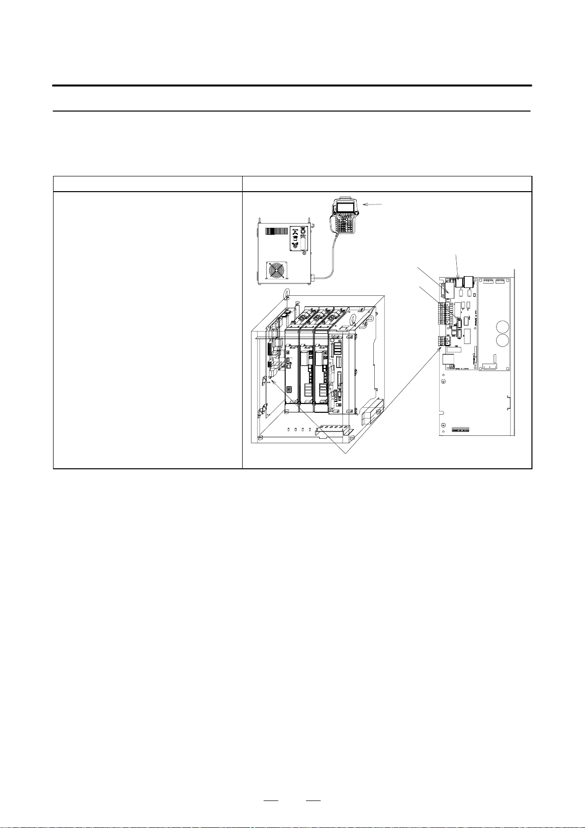
B–81535EN/02
3.1.1
Teach Pendant Cannot
be Turned On
Check and Corrective action Figure
(Check 1) Check the LCD display and LED indica-
(Corrective
action)
tion on the teach pendant.
Check the LCD display and LED indica-
tion on the teach pendant to see whether
the emergency stop unit is faulty.
– Check whether the fuse FUS4 on the
emergency stop board is blown. If the
fuse is blown, the FALM LED glows.
Replace th e b l o w n f u s e .
– If the fuse FUS4 on the emergency
stop board is not blown, the emergency stop unit may be faulty. Replace
the emergency stop unit.
3. TROUBLESHOOTINGMAINTENANCE
Teach pendant
Emergency stop board
FALM LED
Fuse FUS4
Emergency stop unit
27
Page 59
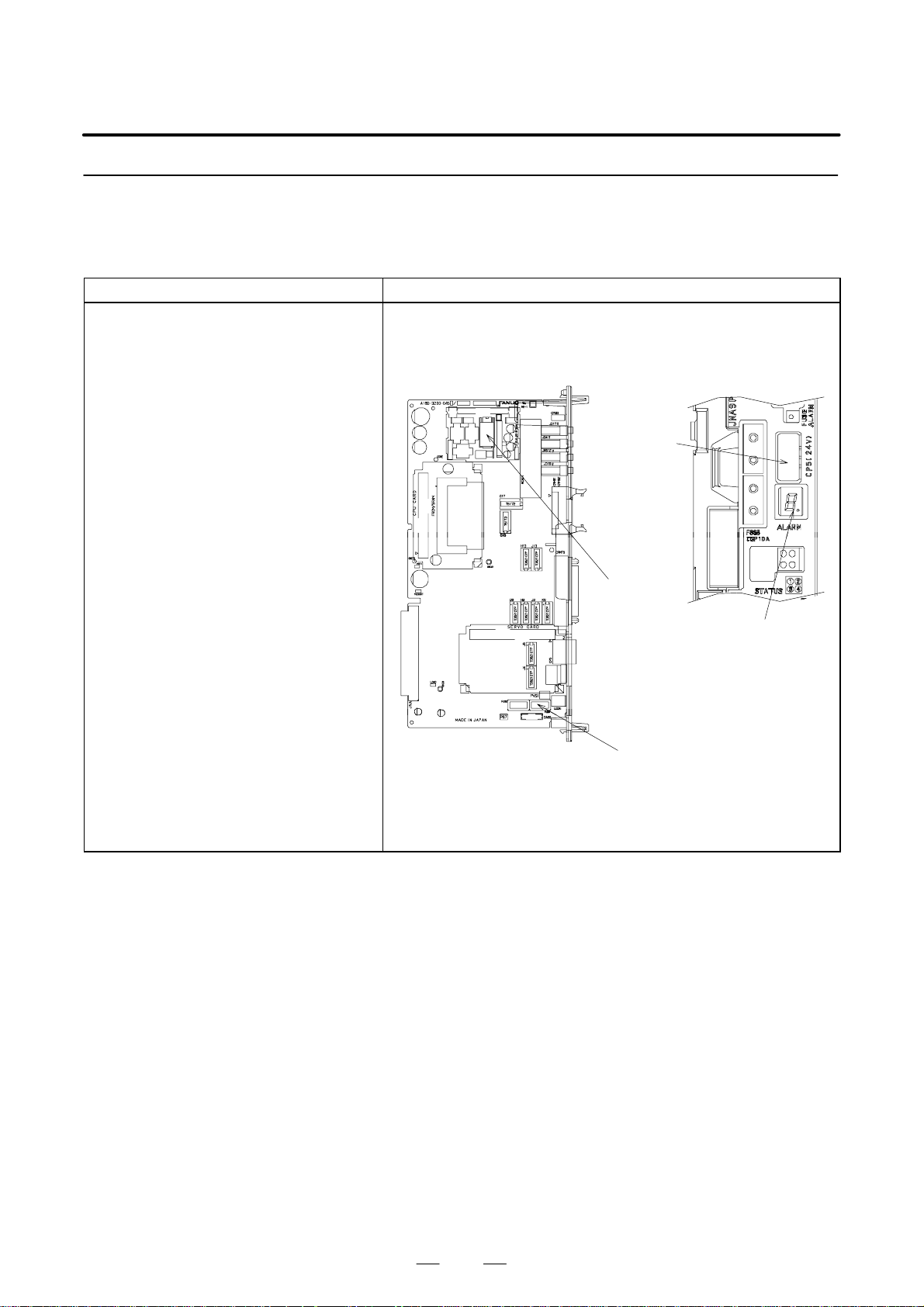
3. TROUBLESHOOTING
3.1.2
Initial Screen Remains
on the Teach Pendant
Check and Corrective action Figure
(Check 1) Check that the “.” portion of the seven–
(Corrective
action)
(Corrective
action(1))
(Corrective
action(2)) a) Problem in the DC/DC converter
segment LED glows on the robot control
board.
If the “.” portion is not glowing, the fuse
FUS1 on the robot control board may be
blown. Alternatively, the DC/DC converter module may be damaged.
If the FUSE ALARM LED is glowing, the
fuse FUS1 may be blown.
The fuse FUS1 is provided on the robot
control board. Before checking the fuse,
turn off the circuit protector.
a) If the fuse FUS1 has been blown
– See Corrective action (1).
b) If the fuse FUS1 is not blown
– See Corrective action (2).
Cause of the blowing of the fuse FUS1
and corrective action
a) Check whether the device which is
connected to the RS–232–C/
RS–422 port and requires the power
supply of +24 V is sound.
b) Problem in the DC/DC converter
module
If the DC/DC converter module gets
faulty in the short–circuit mode,
FUS1 is blown.
Replace the DC/DC converter module.
module
Replace the DC/DC converter module.
b) Problem in the robot control board
Replace the robot control board.
(For the LED indications, see Section
3.7, “TROUBLESHOOTING USING
LEDS.”)
MAINTENANCE
B–81535EN/02
+24V input
connector
CP5
DC/DC converter
module
dot part of seven
segment L E D
FUS1 7.5A
DC24V input fuse
28
Page 60
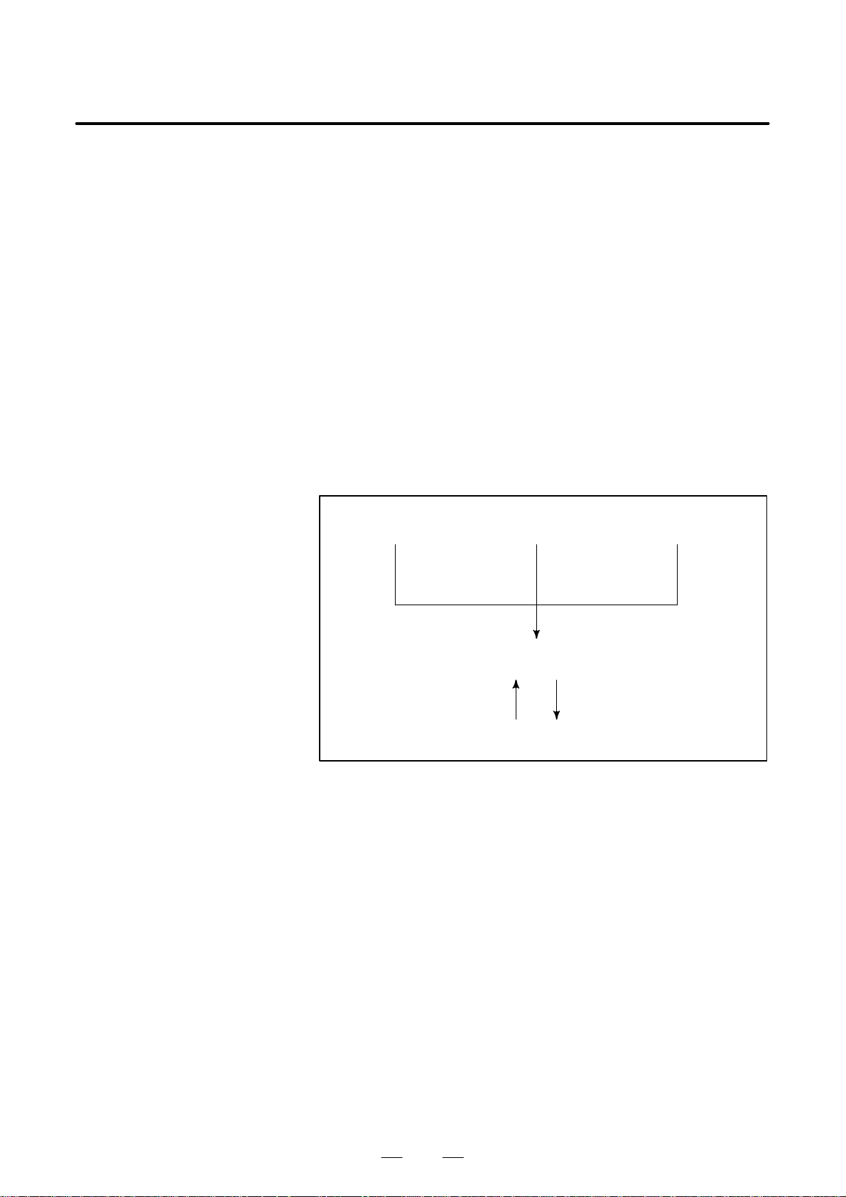
B–81535EN/02
3. TROUBLESHOOTINGMAINTENANCE
3.2
ALARM
OCCURRENCE
SCREEN
The alarm occurrence screen displays only the alarm conditions that are
currently active. If an alarm reset signal is input to reset the alarm
conditions, the alarm occurrence screen displays the message “PAUSE or
more serious alarm has not occurred.”
The alarm occurrence screen displays only the alarm conditions (if any)
that occur after the most recently entered alarm reset signal. To erase all
alarm displays from the alarm occurrence screen. Press the CLEAR key
(+ shift) on the alarm history screen.
The alarm occurrence screen is intended to display PAUSE or more
serious alarms. It will not display WARN, NONE, or a reset. It is possible
to disable PAUSE and some of more serious alarms from being displayed
by setting the $ER_NOHIS system variable appropriately.
If two or more alarms have occurred, the display begins with the most
recent alarm.
Up to 100 lines can be displayed.
If an alarm has a cause code, it is displayed below the line indicating the
alarm.
Press the screen
selection key to select
[4 ALARM].
Press the alarm key.
Automatic alarm display
upon occurrence
Alarm occurrence screen display
Press F3 [ACTIVE]. Press F3 [HIST].
Alarm history screen display
Fig.3.2 Alarm Occurrence Screen and Alarm History Screen Display
Procedure
29
Page 61
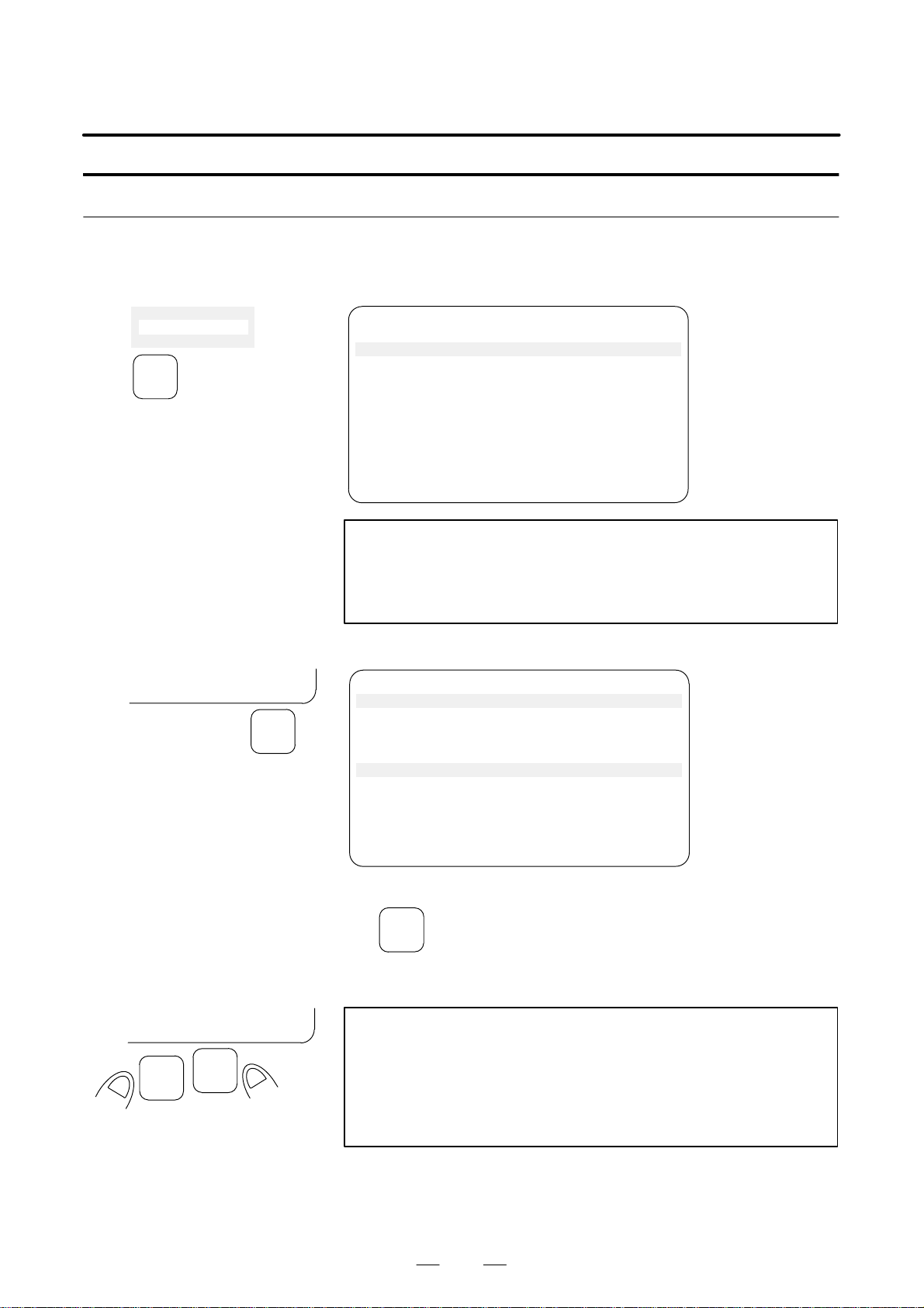
3. TROUBLESHOOTING
Displaying the alarm history/alarm detail information
MAINTENANCE
B–81535EN/02
Step
3
4 ALARM
5 I/O
MENUS
CLEAR HELP
F5
(1) Press the MENUS key to display the screen menu.
(2) Select [ALARM].
You will see a screen similar to the following
INTP–224 (SAMPLE1, 7) Jump label is fail
MEMO–027 Specified line does not exist
Alarm JOINT 30 %
1/25
1 INTP–224 (SAMPLE1, 7) Jump label is
2 SRVO–002 Teach pendant E–stop
3 R E S E T
4 SRVO–027 Robot not mastered(Group:1)
5 SYST–026 System normal power up
[ TYPE ] CLEAR HELP
NOTE
The latest alarm is assigned number 1. To view messages
that are currently not on the screen, press the F5, HELP,
then press the right arrow key.
(3) To display the alarm detail screen, press F5, [HELP].
INTP–224 (SAMPLE1, 7) Jump label is fail
INTP–224 (SAMPLE1, 7) Jump label is fail
MEMO–027 Specified line does not exist
30–MAY–44 07:15
STOP.L 00000110
Alarm
1/25
1 INTP–224 (SAMPLE1, 7) Jump label is
2 SRVO–002 Teach pendant E–stop
CLEAR HELP
SHIFT
F4
[ TYPE ] CLEAR HELP
(4) To return to the alarm history screen, press the PREV key.
PREV
(5) To delete all the alarm histories, press and hold down the SHIFT key,
then press F4, [CLEAR].
NOTE
When system variable $ER_NOHIS = 1, NONE alarms or
WARN alarms are not recorded. When $ER_NOHIS=2,
resets are not recorded in the alarm history. When
$ER_NOHIS=3, resets, WARN alarms, and NONE alarms
are not recorded.
30
Page 62

B–81535EN/02
3. TROUBLESHOOTINGMAINTENANCE
The following map indicates teach pendant operations used to check an
alarm.
4 ALARM
F1 [TYPE]
Alarm : Active
F1 [TYPE]
F3 HIST
Alarm : HIST
F1 [TYPE]
F3 [ACTIVE]
F4 CLEAR
F5 HELP
DETAIL Alarm
F1 [TYPE]
F3 [ACTIVE]
F4 CLEAR
F5 HELP
31
Page 63
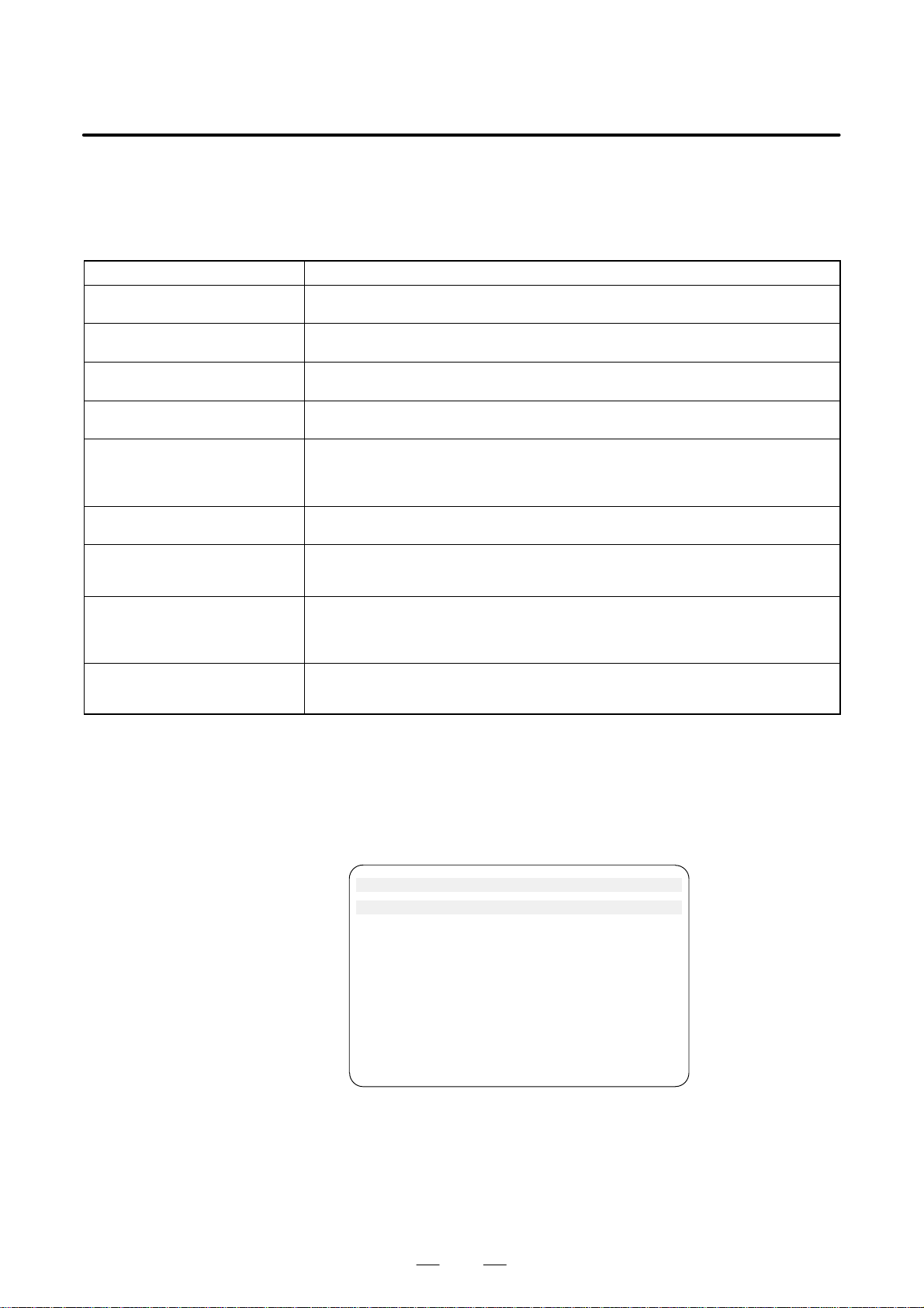
3. TROUBLESHOOTING
MAINTENANCE
B–81535EN/02
3.3
SAFETY SIGNALS
Safety signal
Operator panel emergency stop This item indicates the state of the emergency stop button on the operator panel. If the
Teach pendant emergency stop This item indicates the state of the emergency stop button on the teach pendant. If the
External emergency stop This item indicates the state of the external emergency stop signal. If the EMERGENCY
Fence open This item indicates the state of the safety fence. If the safety fence is open, the state is
Deadman switch This item indicates whether the DEADMAN switch on the teach pendant is grasped. If
Teach pendant operable This item indicates whether the teach pendant is operable. If the teach pendant is oper-
Hand broken This item indicates the state of the hand safety joint. If the hand interferes with a work-
Robot overtravel This item indicates whether the current position of the robot is out of the operation range.
Abnormal air pressure This item indicates the state of the air pressure. The abnormal air pressure signal is con-
The safety signal screen indicates the state of signals related to safety. To
be specific, the screen indicates whether each safety signal is currently on.
On this screen, it is impossible to change the state of any safety signal.
T able 3.3 Safety Signals
Description
EMERGENCY STOP board is pressed, the state is indicated as “TRUE”.
EMERGENCY STOP board is pressed, the state is indicated as “TRUE”.
STOP signal is input, the state is indicated as “TRUE”.
indicated as “TRUE”.
the teach pendant is operable, and the DEADMAN switch is grasped, the state is indicated as “TRUE”. If the deadman switch is released when the teach pendant is operable,
an alarm occurs, causing the servo power to be switched off.
able, the state is indicated as “TRUE”.
piece or anything like this, and the safety joint is opened, the state is indicated as
“TRUE”. In this case, an alarm occurs, causing the servo power to be switched off.
If any robot articulation goes out of the operation range beyond the overtravel switch, the
state is indicated as “TRUE”. I n this case, an alarm o ccur s, causi ng t he ser vo p ower t o b e
switched off.
nected to the air pressure sensor. If the air pressure is not higher than the specified
value, the state is indicated as “TRUE”.
Step
(1) Press the MENUS key to display the screen menu.
(2) Select STATUS on the next page.
(3) Press F1, [TYPE] to display the screen switching menu.
(4) Select Safety Signal. You will see a screen similar to the following.
SYSTEM Safety JOINT 30%
SIGNAL NAME STATUS 1/11
1 SOP E–Stop: FALSE
2 TP E–stop: FALSE
3 Ext E–Stop: FALSE
4 Fence Open: FALSE
5 TP Deadman: TRUE
6 TP Enable: TRUE
7 Hand Broken: FALSE
8 Over Travel: FALSE
9 Low Air Alarm: FALSE
[TYPE]
32
Page 64

B–81535EN/02
3. TROUBLESHOOTINGMAINTENANCE
3.4
MASTERING
Condition
Step
9 USER
0 –– NEXT ––
MENUS
5 POSITION
6 SYSTEM
7
Mastering is needed if:
(1) The SRVO 062 BZAL or SRVO 038 pulse mismatch alarm occurs,
or
(2) The pulse coder is replaced.
Item (1) requires simplified mastering, while item (2) requires
zero–degree or jig position mastering. (Zero–degree position mastering
is just for quick–fix purposes. After zero–degree position mastering is
used, jig position mastering should be performed later.)
The mastering procedure is described below. For details, refer to an
applicable maintenance manual of mechanical unit or operator’s manual
of control unit.
System variable $MASTER_ENB must be set to 1 or 2.
SYSTEM Variables JOINT 10%
57/136
57 $MASTER_ENB 1
(1) Press <MENUS>.
(2) Select SYSTEM.
(3) Press F1, TYPE.
(4) Select Master/Cal you will see a screen similar to the following.
SYSTEM Master/Cal JOINT 30%
1 FIXTURE POSITION MASTER
2 ZERO POSITION MASTER
3 QUICK MASTER
4 SINGLE AXIS MASTER
5 SET QUICK MASTER REF
6 CALIBRATE
Master/Cal
TYPE
F1
Press ’ENTER’ or number key to select.
[TYPE] LOAD RES_PCA DONE
(5) Move the robot by jog feed to the mastering position. Release the
brake on the manual brake control screen if necessary.
NOTE
Mastering can not be performed until axis is rotated enough
to establish a pulse.
33
Page 65
3. TROUBLESHOOTING
MAINTENANCE
B–81535EN/02
(6) Select “1 FIXTURE POSITION MASTER” and press the F4 key
(yes). Mastering data is set.
SYSTEM Master/Cal
1 FIXTURE POSITION MASTER
2 ZERO POSITION MASTER
Master at master position? [NO]
Master at master position? [NO]
[ TYPE ] YES NO
ENTER
F4
(7) Select “6 CALIBRATE” and press the F4 key (yes). Calibration is
5 SET QUICK MASTER REF
6 CALIBRATE
Calibrate? [NO]
Calibrate? [NO]
[ TYPE ] YES NO
ENTER
F4
SYSTEM Master/Cal JOINT 30 %
1 FIXTURE POSITION MASTER
2 ZERO POSITION MASTER
3 QUICK MASTER
4 SINGLE AXIS MASTER
5 SET QUICK MASTER REF
6 CALIBRATE
Robot Mastered! Mastering Data:
<0> <11808249> <38767856>
<9873638> <122000309> <2000319>
[ TYPE ] LOAD RES_PCA DONE
performed.
Alternatively, to perform positioning, turn the power off, then turn it
on again. Calibration is performed whenever the power is turned on.
SYSTEM Master/Cal JOINT 30 %
1 FIXTURE POSITION MASTER
2 ZERO POSITION MASTER
3 QUICK MASTER
4 SINGLE AXIS MASTER
5 SET QUICK MASTER REF
6 CALIBRATE
Robot Calibrated! Cur Jnt Ang(deg):
<10.000> <–25.000> <40.000>
<5.000> <–15.000> <0.000>
[ TYPE ] LOAD RES_PCA DONE
DONE
F5
(8) Press F5 “DONE”, after mastering.
34
Page 66

B–81535EN/02
3. TROUBLESHOOTINGMAINTENANCE
3.5
TROUBLESHOOTING
USING THE ERROR
CODE
Emergency stop button
(1) SRVO–001 SVAL1 Operator panel E–stop
(Explanation) The EMERGENCY STOP button on the operator
panel is pressed.
(Action 1) Release the emergency stop button pressed on the
operator panel.
(Action 2) Release the EMERGENCY STOP button on the
operator panel.
(Action 3) Replace the emergency stop unit.
Before taking (Action 4), make a backup copy of all
the programs and settings of the control unit.
(Action 4) Replace the robot control board.
Operator
panel
Fig.3.5 (1) (a) SRVO–001 SVAL1 Operator panel E–stop
Robot control board
Emergency stop unit
35
Page 67

3. TROUBLESHOOTING
MAINTENANCE
B–81535EN/02
(2) SRVO–002 SVAL1 Teach pendant E–stop
(Explanation) The emergency stop button on the operator’s Teach
Pendant was pressed.
(Action 1) Release the emergency stop button on the teach
pendant.
(Action 2) Replace Teach Pendant.
Emergency stop button
Fig.3.5 (2) SRVO–002 SVAL1 Teach pendant E–stop
(3) SRVO–003 SVAL1 Deadman switch released
(Explanation) The teach pendant is enabled, but the deadman switch
is not pressed.
(Action 1) Press the deadman switch to run the robot.
(Action 2) Replace the teach pendant.
Deadman switch
Fig.3.5 (3) SRVO–001 SVAL1 Deadman switch released
36
Page 68
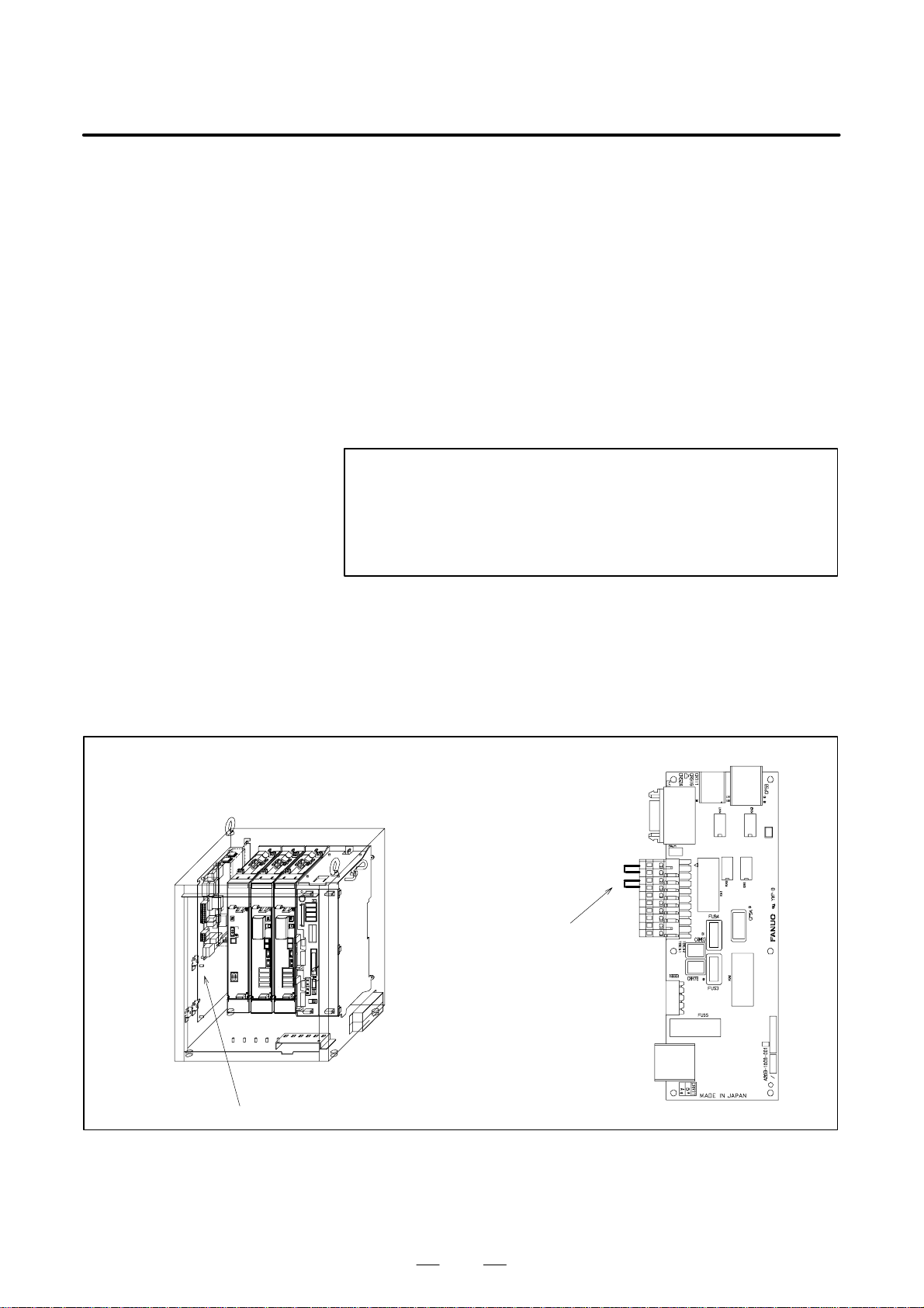
B–81535EN/02
3. TROUBLESHOOTINGMAINTENANCE
(4) SRVO–004 SVAL1 Fence open
(Explanation) In AUTO mode, there is no short circuit between
FENCE11 and FENCE12 and between FENCE21
and FENCE22 on the terminal block TBEB5 of the
emergency stop board.
If the safety fence is connected between FENCE11
and FENCE12 and between FENCE21 and
FENCE22, the door of the safety fence is open.
(Action 1) When the safety fence is connected, close the door.
(Action 2) Check the cables and switches connected to
FENCE11, FENCE12, FENCE21 and FENCE22.
(Action 3) When this signal is not used, short–circuit between
FENCE11 and FENCE12 and between FENCE21
and FENCE22.
NOTE
In the system that uses the fence signal, do not short–circuit
this signal to disable it because the operation is dangerous.
When this signal must be temporarily short–circuited, make
safety provisions separately.
(Action 4) When AUTO mode is not entered even though the
mode switch is set to AUTO, the mode switch may be
faulty. Replace the operator panel.
(Action 5) Replace the emergency stop unit.
Before taking (Action 6), make a backup copy of all
the programs and settings of the control unit.
(Action 6) Replace the robot control board.
Short connection boards:
two positions (terminal blocks
located on the right when
viewing from the front)
Emergency stop unit
Fig.3.5 (4) SRVO–004 SVAL1 Fence open
37
Page 69
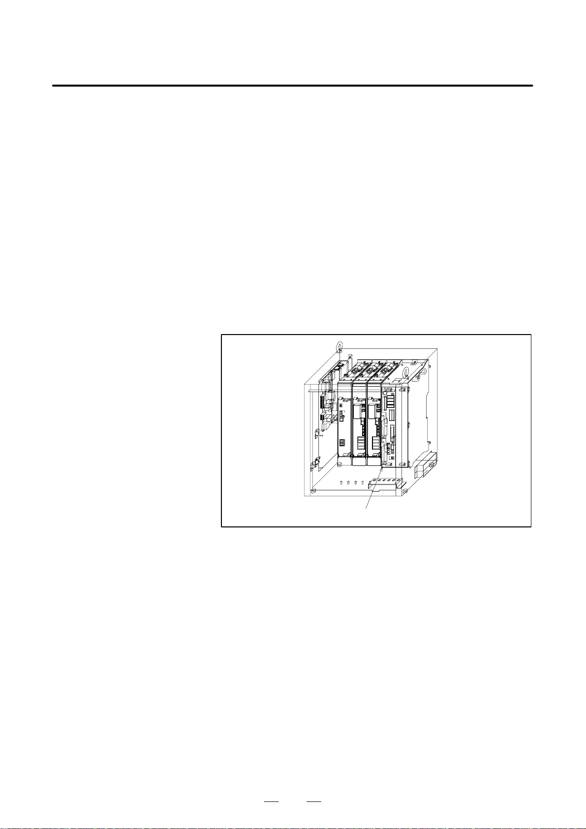
3. TROUBLESHOOTING
MAINTENANCE
B–81535EN/02
(5) SRVO–005 SVAL1 Robot overtravel
(Explanation) This alarm should not occur because no overtravel
input signal is provided. However, this alarm can be
caused by an abnormal overtravel input signal across
the robot interconnection cable and robot control
board.
(Action 1) Check the robot interconnection cable (RMP) for the
following.
1) The male and female connection pins are not
twisted or are not loose.
2) The connector is securely connected.
3) The cable is free from a break and ground fault.
Next, check that the connector CRM82 of the robot
control board is securely connected. In addition,
check that the RMP cable is sound and free from a
break or visible twist.
Before taking (Action 2), make a backup copy of all
the programs and settings of the control unit.
(Action 2) Replace the robot control board.
Robot control board
Fig.3.5 (5) SRVO–005 SVAL1 Robot overtravel
38
Page 70

B–81535EN/02
3. TROUBLESHOOTINGMAINTENANCE
(6) SRVO–006 SVAL1 Hand broken
(Explanation) The safety joint, if any, is broken. If no joint is
broken, the HBK signal line of the robot
interconnection cable has a break or ground fault.
(Action 1) Holding down the shift key, press the alarm release
button. This releases the alarm. Keeping on holding
down the shift key, carry out jog feed to move the tool
to the work area.
1) Replace the safety joint.
2) Examine the cable.
(Action 2) Check the robot interconnection cable (RMP) for the
following.
1) The male and female connection pins are not
twisted or are not loose.
2) The connector is securely connected.
3) The cable is free from a break and ground fault.
Next, check that the connector CRM82 of the robot
control board is securely connected. In addition,
check that the RMP cable is sound and free from a
break or visible twist.
Before taking (Action 3), make a backup copy of all
the programs and settings of the control unit.
(Action 3) Replace the robot control board.
Robot control board
Fig.3.5 (6) SRVO–006 SVAL1 Hand broken
39
Page 71
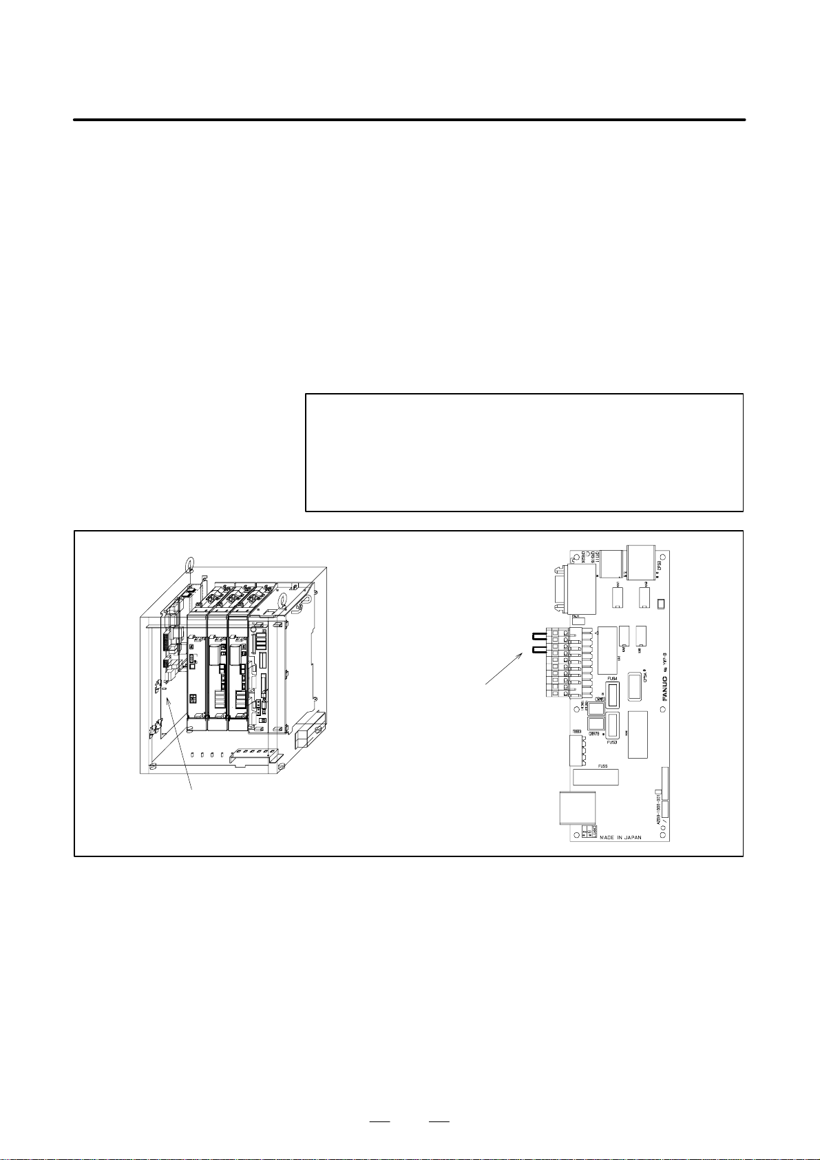
3. TROUBLESHOOTING
MAINTENANCE
B–81535EN/02
(7) SRVO–007 SVAL1 External E–stop
(Explanation) EMGIN11 and EMGIN12/EMGIN21 and EMGIN22
on the terminal block TB EB5 of the emergency stop
board are not short–circuited. If an external e mer ge nc y
stop switch is connected across EMGIN11 and
EMGIN12/EMGIN21 and EMGIN22, the switch has
been pres sed .
(Action 1) If an external emergency stop switch is connected,
releases the switch.
(Action 2) Check the switch and cable connected to EMGIN11
and EMGIN12 and to EMGIN21 and EMGIN22.
(Action 3) When this signal is not used, make a connection
between EMGIN11 and EMGIN12 and a connection
between EMGIN21 and EMGIN22. (WARNING)
(Action 4) Replace the emergency stop unit.
WARNING
Do NOT short–circuit, or disable, this signal in a system in
which the External emergency stop input signal is in use, as
it is very dangerous. If it is necessary to run the robot by
short–circuiting the signal even temporarily, an additional
safety provision must be provided.
Emergency stop unit
Short connection boards:
two positions (terminal blocks
located on the left when
viewing from the front)
Fig.3.5 (7) SRVO–007 SVAL1 External E–stop
40
Page 72

B–81535EN/02
3. TROUBLESHOOTINGMAINTENANCE
(8) SRVO–009 SVAL1 Pneumatic pressure alarm
(Explanation) An abnormal air pressure was detected. The input
signal is located on the end effector of the robot.
Refer to the manual of your robot.
(Action 1) If an a bnorma l a ir p r essur e i s d e tec ted , c hec k t he cause.
If the peripheral device are normal, check the robot
connection cable.
Before taking (Action 2), make a backup copy of all
the programs and settings of the control unit.
(Action 2) Replace the robot control board.
Robot control board
Fig.3.5 (8) SRVO–009 SVAL1 Pneumatic pressure alarm
41
Page 73
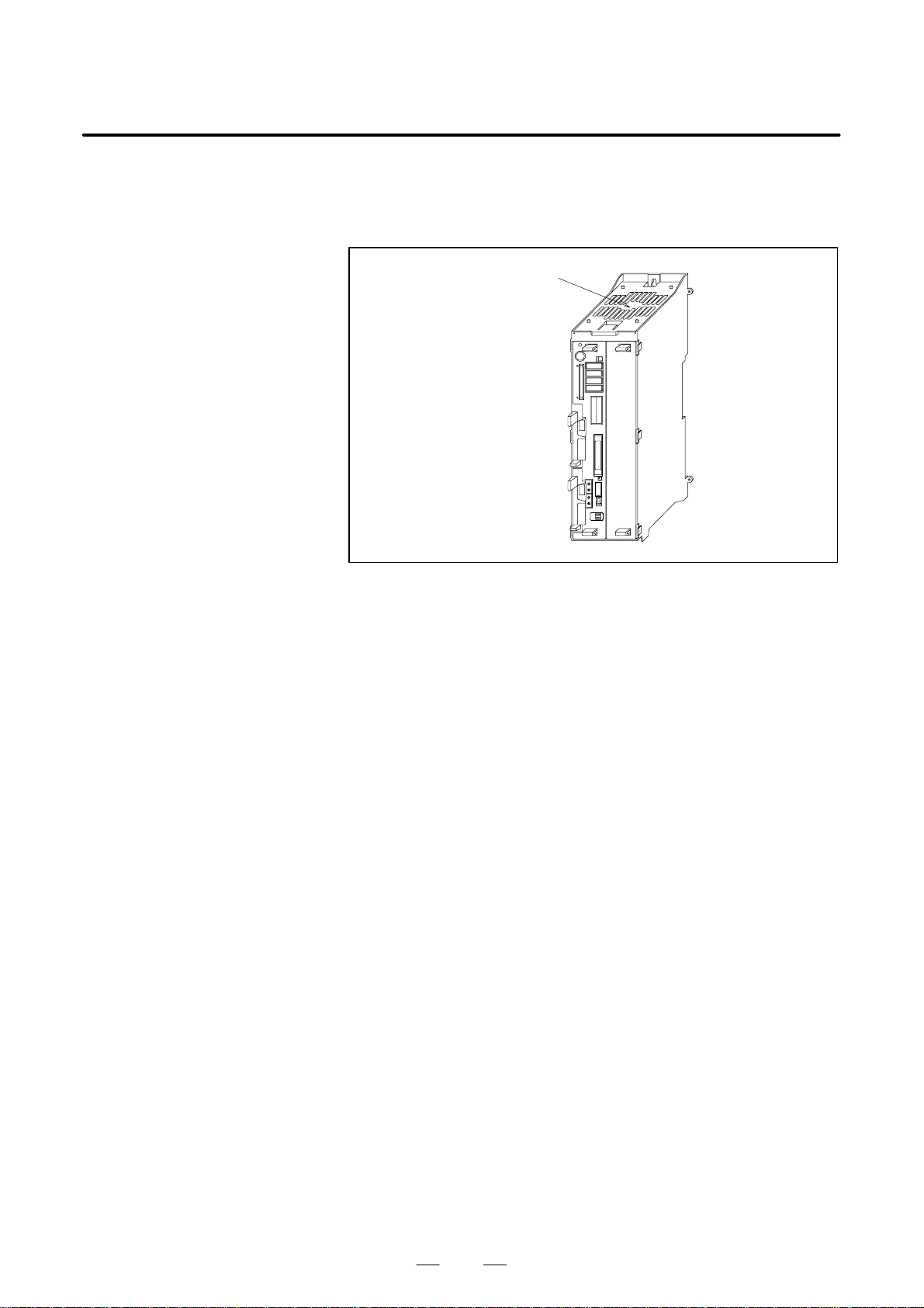
3. TROUBLESHOOTING
MAINTENANCE
B–81535EN/02
(9) SRVO–014 WARN Fan motor abnormal
(Explanation) A fan motor in the backplane unit is abnormal.
(Action) Check the fan motor and its cables. Replace them if
necessary.
Fan motor
Fig.3.5 (9) SRVO–014 WARN Fan motor abnormal
42
Page 74
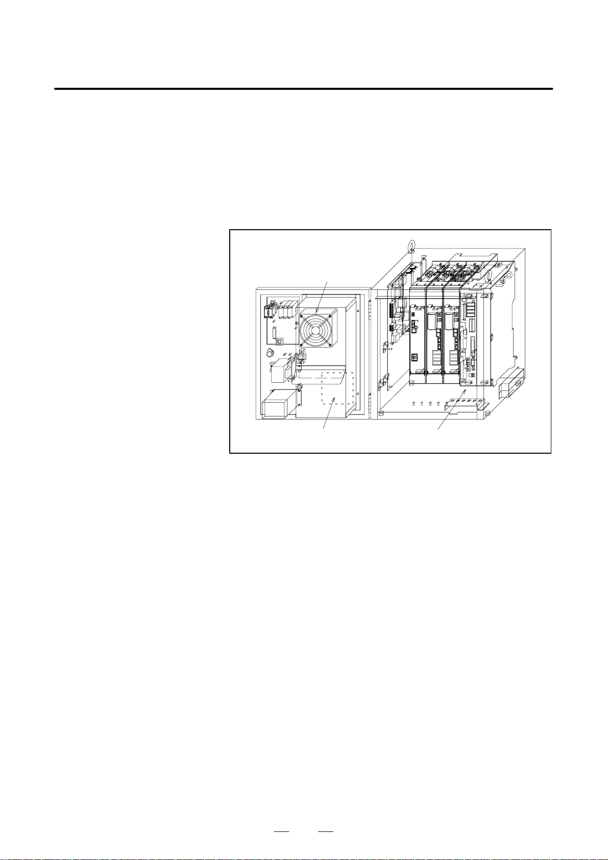
B–81535EN/02
3. TROUBLESHOOTINGMAINTENANCE
(10)SRVO–015 SVAL1 SYSTEM OVER HEAT (Group : i Axis : j)
(Explanation) The temperature in the control unit exceeds the
specified value.
(Action 1) If the ambient temperature is higher than specified
(45°C), cool down ambient temperature.
(Action 2) If the fan motor is not running, check it and its cables.
Replace them if necessary.
(Action 3) If the thermostat on the robot control board is
defective, replace the robot control board.
Fan motor
(on the heat exchange)
Fan motor (door face) Robot control board
Fig.3.5 (10) SRVO–015 SVAL1 SYSTEM OVER HEAT
43
Page 75

3. TROUBLESHOOTING
MAINTENANCE
B–81535EN/02
(11)SRVO–021 SVAL1 SRDY off (Group : i Axis : j)
(Explanation) The HRDY is on and the SRDY is off, although there
is no other cause of an alarm. (HRDY is a signal with
which the host detects the servo system whether to
turn on or off the servo amplifier magnetic contactor.
SRDY is a signal with which the servo system
informs the host whether the magnetic contactor is
turned on.)
If the servo amplifier magnetic contactor cannot be
turned on when directed so, it is most likely that a
servo amplifier alarm has occurred. If a servo
amplifier alarm has been detected, the host will not
issue this alarm (SRDY off). Therefore, this alarm
indicates that the magnetic contactor cannot be turned
on for an unknown reason.
(Action 1) Measure the voltage of the 200–VAC input to the
power supply module. If the voltage is 170 VAC or
lower, adjust the input voltage.
(Action 2) Check that CRR78 of the emergency stop board and
CX3 and CX4 of the power supply module are
securely connected. Check the cables of the
emergency stop board and power supply module for
a break.
(Action 3) Check the EMERGENCY STOP line (teach pendant
emergency stop, teach pendant enable/disable switch,
teach pendant deadman switch, operator panel
emergency stop, external emergency stop input, fence
input) for a possibility of an instantaneous
interruption. If the software cannot judge the cause
of the alarm at an instantaneous interruption of the
EMERGENCY STOP line, this alarm occurs.
(Action 4) Replace the emergency stop unit.
(Action 5) If an alarm occurs on all axes, the power supply
module may be faulty. Replace the power supply
module.
(Action 6) If an alarm occurs on a particular axis, the servo
amplifier module may be faulty. Replace the servo
amplifier module controlling the axis.
(Action 7) Replace the axis control card on the robot control
board.
44
Page 76
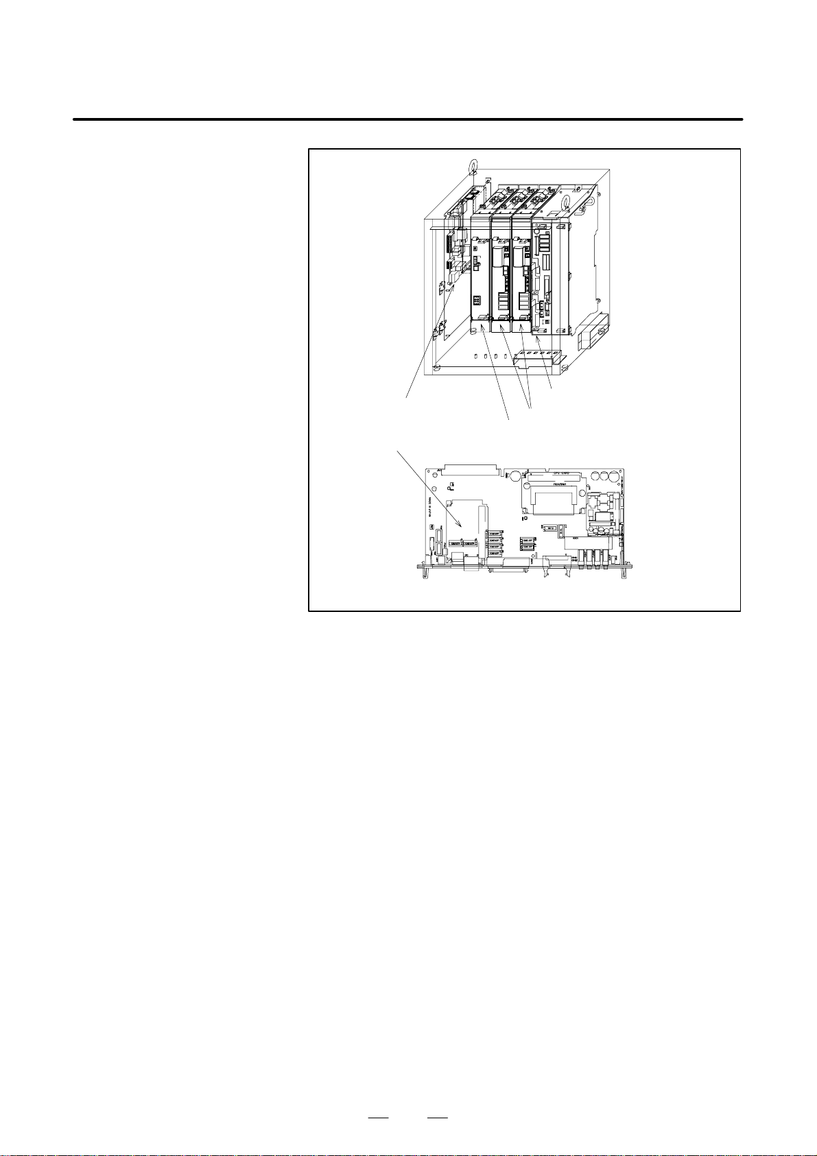
B–81535EN/02
3. TROUBLESHOOTINGMAINTENANCE
Emergency stop unit
Power supply module
Axis control card
Robot control board
Servo amplifier module
Fig.3.5 (11) SRVO–021 SVAL1 SRDY off
45
Page 77
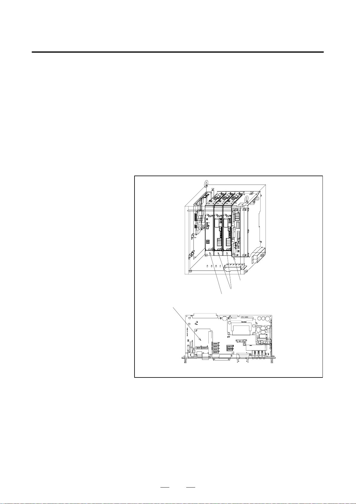
3. TROUBLESHOOTING
MAINTENANCE
B–81535EN/02
(12)SRVO–022 SVAL1 SRDY on (Group : i Axis : j)
(Explanation) When the HRDY is about to go on, the SRDY is already
on. (HR DY is a signal with which the host di rects the
servo system whether to turn on or off the servo
amplifier magnetic contactor. SRDY is a signal with
which the servo system informs the host whether the
magnetic contactor is turned on.
(Action 1) Replace the axis control card on the robot control
board.
(Action 2) If an alarm occurs on all axes, the power supply
module may be faulty. Replace the power supply
module.
(Action 3) If an alarm occurs on a particular axis, the servo
amplifier module may be faulty. Replace the servo
amplifier module controlling the axis.
Robot control board
Servo amplifier module
Power supply module
Axis control card
Fig.3.5 (12) SRVO–022 SVAL1 SRDY on
46
Page 78
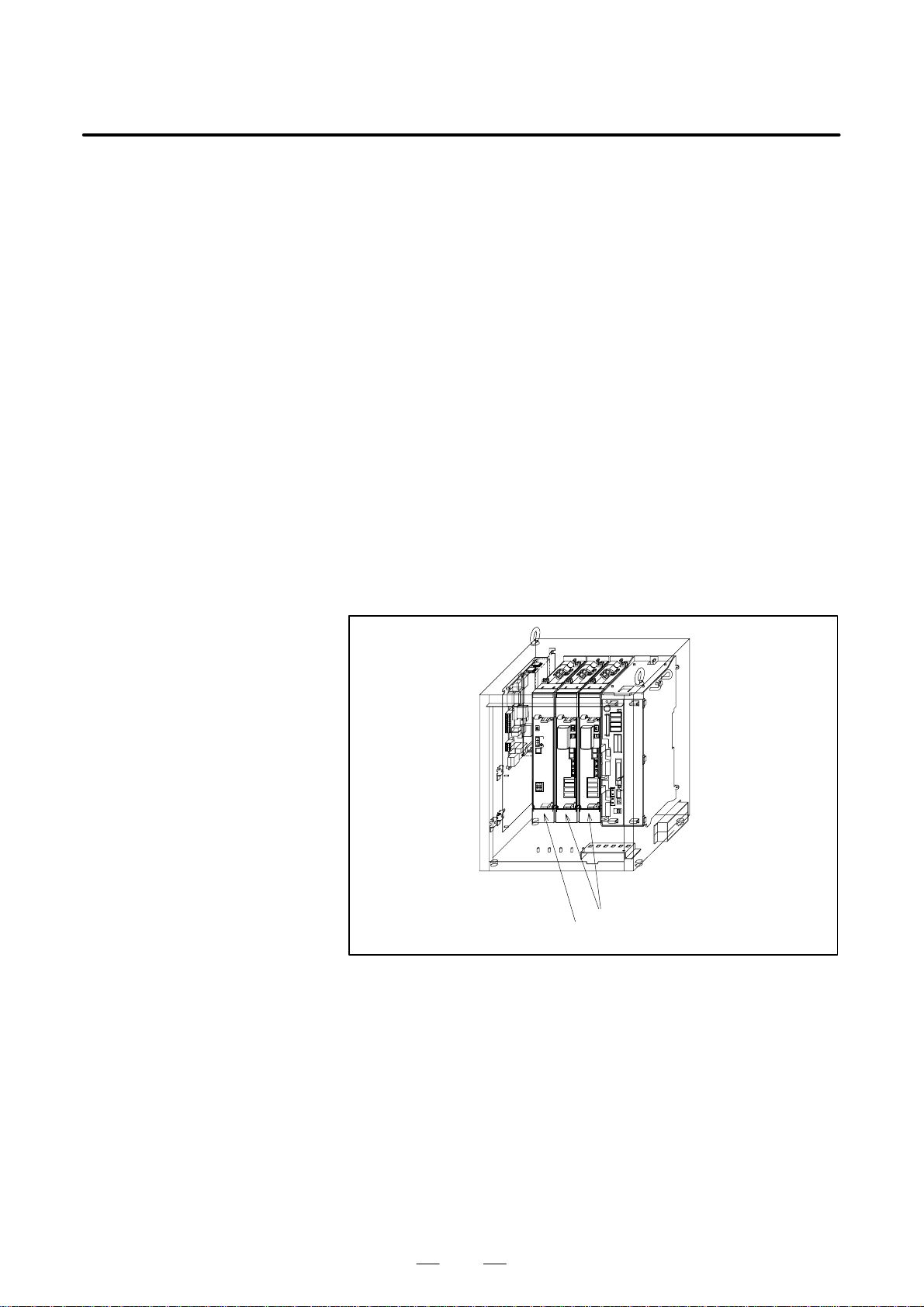
B–81535EN/02
3. TROUBLESHOOTINGMAINTENANCE
(13)SRVO–023 SVAL1 Stop error excess (Group : i Axis : j)
(Explanation) When the servo is at stop, the position error is
abnormally large.
(Action 1) Check whether the motor brake has been released.
(Action 2) Make sure that the servo amplifier CZ2L to N are
connected tightly.
(Action 3) Check to see if the load is greater than the rating. If
greater, reduce it to within the rating. (If the load is
too greater, the torque required for acceleration /
deceleration becomes h igher than the capaci ty of the
motor. As a result, the motor becomes unable to
follow the command, and an alarm is issued.)
(Action 4) Check each phase voltage of the CZ1 connector of the
three–phase power (200 VAC) input to the servo
amplifier. If it is 170 VAC or lower, check the line
voltage. (If the voltage input to the servo amplifier
becomes low, the torque output also becomes low. As
a result the motor may become unable to follow the
command, hence possibly an alarm.)
(Action 5) If the line voltage is 170 VAC or higher, replace the
power supply module or servo amplifier module.
(Action 6) Check disconnection of robot connection cable
(RMP).
(Action 7) Replace the motor.
Servo amplifier module
Power supply module
Fig.3.5 (13) SRVO–023 SVAL1 Stop error excess
47
Page 79

3. TROUBLESHOOTING
MAINTENANCE
B–81535EN/02
(14)SRVO–024 SVAL1 Move error excess (Group : i Axis : j)
(Explanation) When the robot is running, its position error is greater
than a specified value ($PARAM _ GROUP.
$MOVER _ OFFST or $PARAM _ GROUP.
$TRKERRLIM). It is likely that the robot cannot
follow the speed specified by program.
(Action 1) Check the robot for binding axis.
(Action 2) Take the same actions as described for the above
alarm.
(15)SRVO–025 SVAL1 Motn dt overflow (Group : i Axis : j)
(Explanation) The specified value is too great.
(16)SRVO–026 WARN2 Motor speed limit (Group : i Axis : j)
(Explanation) A value higher than the maximum motor speed
($PARAM_GROUP.$MOT_SPD_LIM) was
specified. The actual motor speed is clamped to the
maximum speed.
(17)SRVO–027 WARN Robot not mastered (Group : i)
(Explanation) An attempt was made to calibrate the robot, but the
necessary adjustment had not been completed.
(Action) Master the robot.
(18)SRVO–030 SVAL1 Brake on hold (Group : i)
(Explanation) This alarm occurs when the robot pauses, if the brake
on hold function has been enabled ($SCR.
$BRKHOLD _ ENB = 1). Di sable the function if it is
not necessary.
(Action) Disable [Servo–off during pause] on the general
setting menu (Select Setting general).
(19)SRVO–031 SVAL1 User servo alarm (Group : i)
(Explanation) An user servo alarm occurred.
(20)SRVO–033 WARN Robot not calibrated (Group : i)
(Explanation) An attempt was made to set up a reference point for
simplified adjustment, but the robot had not been
calibrated.
(Action) Calibrate the robot.
1.Supply power.
2.Set up a simplified adjustment reference point
using [Positioning] on the positioning menu.
(21)SRVO–034 WARN Ref pos not set (Group : i)
(Explanation) An a ttempt w as m ade t o perform simplifie d adjustment,
but the reference point had not been set up.
(Action) Set up a simplified adjustment reference point on the
positioning menu.
(22)SRVO–035 WARN2 Joint speed limit (Group : i Axis : j)
(Explanation) A value higher than the maximum axis speed
($PARAM_GROUP.$JNTVELLIM) was specified.
Each actual axis speed is clamped to the maximum
speed.
(23)SRVO–036 SVAL1 Inpos time over (Group : i Axis : j)
(Explanation) The robot did not get to the effective area ($PARAM _
GROUP.$ STOPTOL) even after the position check
monitoring time ($PARAM _ GROUP. $INPOS _
TIME) elapsed.
(Action) Take the same actions as for SR VO–23 (lar ge position
error at a stop).
(24)SRVO–037 SVAL1 Imstp input (Group : i)
(Explanation) The *IMSTP signal for a peripheral device interface
was input.
(Action) Turn on the *IMSTP signal.
48
Page 80

B–81535EN/02
3. TROUBLESHOOTINGMAINTENANCE
(25)SRVO–038 SVAL2 Pulse mismatch (Group : i Axis : j)
(Explanation) The pulse count obtained when power is turned off
does not match the pulse count obtained when power
is applied. This alarm is asserted after exchange the
pulsecoder or battery for back up of the pulsecoder
data or loading back up data to the Robot control
board.
(Action) Perform Absolute Pulse Coder reset and remaster
robot (RES–PCA)
1. Press MENUS.
2. Select SYSTEM.
3. Press F1 [TYPE].
4. Select MASTER/CAL.
5. Press F3, PES–PCA and YES.
6. Execute mastering.
7. Press RESET.
The fault condition should reset. If the controller
is still faulted with additional servo–related errors,
cold start the controller.
It might be necessary to remaster the robot.
(26)SRVO–041 SVAL2 MOFAL alarm (Group : i Axis : j)
(Explanation) The servo value was too high.
(Action) Cold start the controller.
49
Page 81
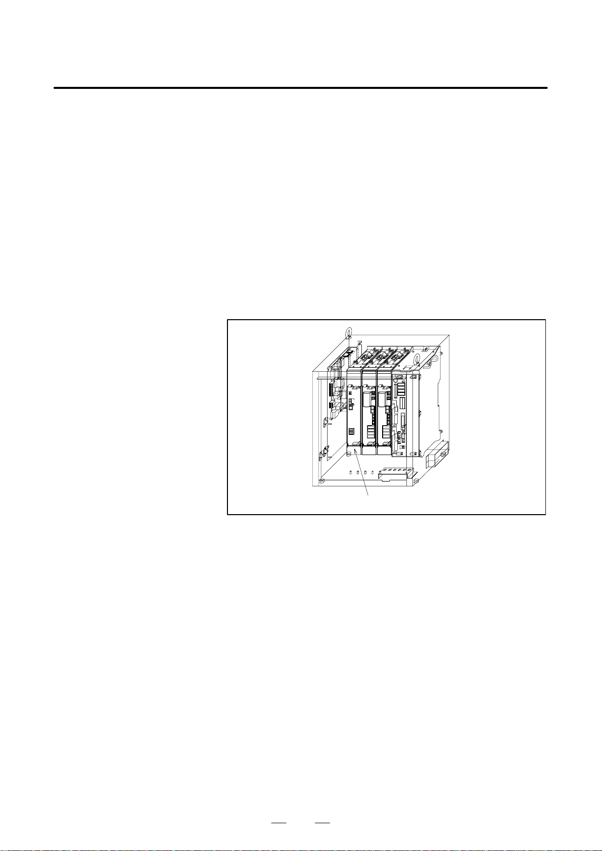
3. TROUBLESHOOTING
MAINTENANCE
B–81535EN/02
(27)SRVO–044 SVAL1 HVAL alarm (Group : i Axis : j)
(Explanation) The DC voltage (DC link voltage) of the main circuit
power supply is abnormally high.
The LED indication on the power supply module is
“7” (HVAL).
(Action 1) Check the three–phase input voltage at the power
supply module. If it is 253 VAC or higher, check the
line voltage. (If the three–phase input voltage is
higher than 253 VAC, high acceleration/deceleration
can result in this alarm.)
(Action 2) Check that the load weight is within the rating. If it
is higher than the rating, reduce it to within the rating.
(If the machine load is higher than the rating, the
accumulation of regenerative energy might result in
the HVAL alarm even when the three–phase input
voltage is within the rating.
(Action 3) Replace the power supply module.
Power supply module
Fig.3.5 (27) SRVO–044 SVAL1 HVAL alarm
50
Page 82

B–81535EN/02
3. TROUBLESHOOTINGMAINTENANCE
(28)SRVO–045 SVAL1 HCAL alarm (Group : i Axis : j)
(Explanation) Abnormally high current flowed in the main circuit of
the servo amplifier module.
The LED indications on the servo amplifier modules
are “b”, “C”, and “d”.
(Action 1) Disconnect the Robot connection cable (Motor power)
from the connector CZ2 of the servo amplifier
module. If error occurs, replace the servo amplifier.
(Action 2) Disconnect the Robot connection cable (Motor power)
from the servo amplifier module connector (CZ2),
and check the insulation of each Robot connection
cable (Motor power) (U, V, or W) and the GND line.
If there is a short–circuit, the motor, robot
interconnection cable, or intra–robot cable is
defective. Check t hem and repl ace them i f necessary.
(Action 3) Disconnect the Robot connection cable (Motor power)
from the servo amplifier module connector (CZ2),
and measure the resistance between the U and V, V
and W , and W and U with a ohmmeter with a very low
resistance range. If the resistances at these three
places are different from each other, the motor, robot
interconnection cable, or intra–robot cable is
defective. Check each item in detail.
Before taking (Action 4), make a backup copy of all
the programs and settings of the control unit.
(Action 4) Replace the robot control board.
Robot control board
Servo amplifier module
Fig.3.5 (28) SRVO–045 SVAL1 HCAL alarm
51
Page 83

3. TROUBLESHOOTING
MAINTENANCE
B–81535EN/02
(29)SRVO–046 SVAL2 OVC alarm (Group : i Axis : j)
(Explanation) This alarm is issued to prevent the motor from
thermal damage that might occur when the root meant
square current calculated within the servo system is
out of the allowable range.
(Action 1) Check the operating conditions for the robot and relax
the service conditions.
(Action 2) Check each phase voltage of the three–phase input
power (200 VAC for the power supply module. If it
is 170 VAC or lower, check the line voltage.
(Action 3) Replace the power supply module and servo
amplifier module.
(Action 4) Check the robot connection cable (RMP).
(Action 5) Replace the motor.
Servo amplifier module
Power supply module
Fig.3.5 (29) SRVO–046 SVAL2 OVC alarm
52
Page 84
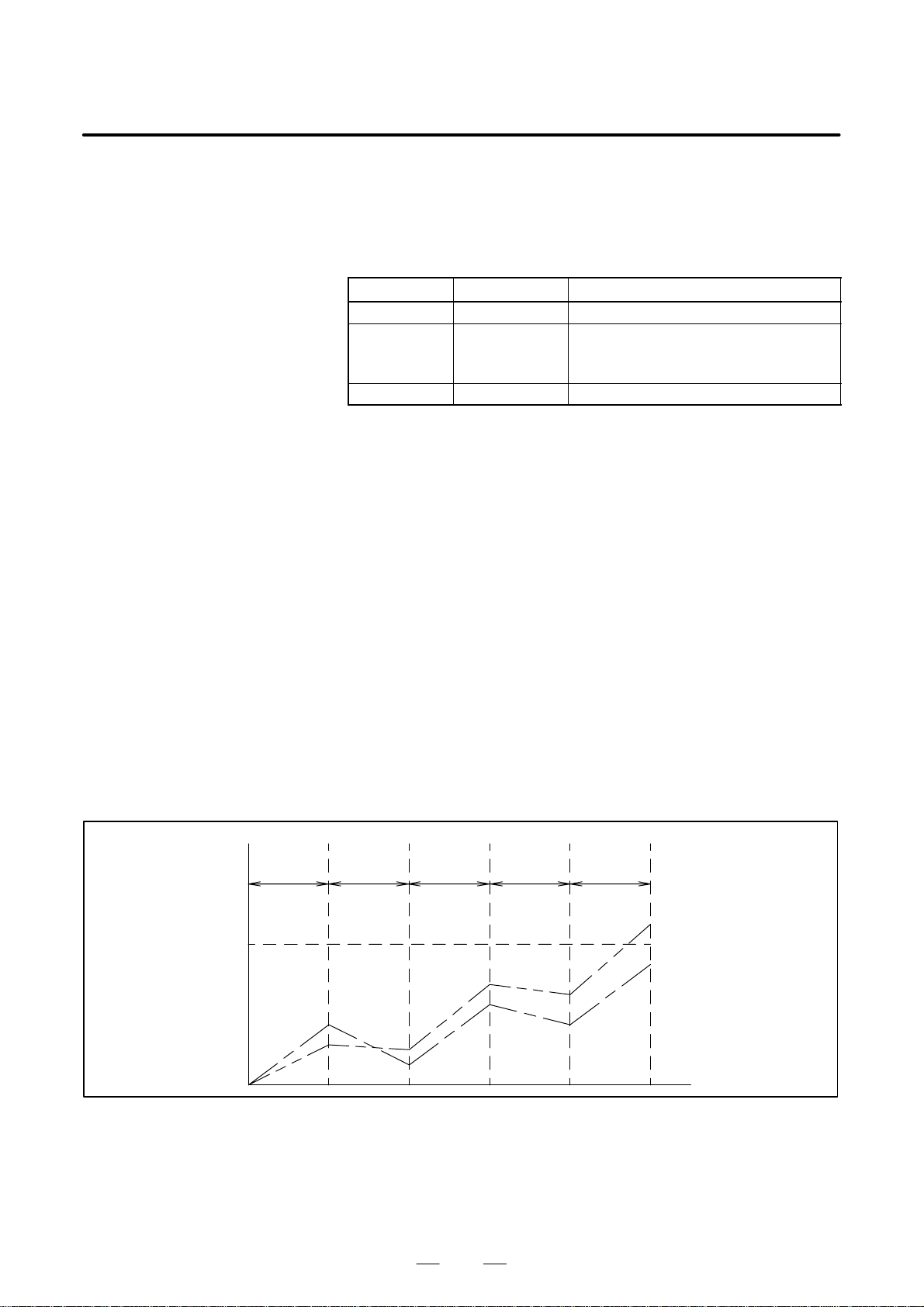
B–81535EN/02
3. TROUBLESHOOTINGMAINTENANCE
Reference
Relationships among the OVC, OVL, and HC alarms
Overview
This section points out the differences among the OVC, OVL, and HC
alarms and describes the purpose of each alarm.
Alarm detection section
Abbreviation Designation Detection section
OVC
OVL
HC
Overcurrent alarm Servo software
Overload alarm Thermal relay in the motor OHAL2
Thermal relay in the servo amplifier OHAL1
Thermal relay in the separate regenerative discharge unit DCAL
High current alarm Servo amplifier
Purpose of each alarm
1) HC alarm (high current alarm)
If high current flow in a power transistor momentarily due to
abnormality or noise in the control circuit, the power transistor and
rectifier diodes might be damaged, or the magnet of the motor might
be degaussed. The HC alarm is intended to prevent such failures.
2) OVC and OVL alarms (overcurrent and overload alarms)
The OVC and OVL alarms are intended to prevent overheat that may
lead to the burnout of the motor winding, the breakdown of the servo
amplifier transistor, and the separate regenerative resistor.
The OVL alarm occurs when each built–in thermal relay detects a
temperature higher than the rated value. However, this method is not
necessarily perfect to prevent these failures. For example, if the
motor frequently repeats to start and stop, the thermal time constant
of the motor, which has a large mass, becomes higher than the time
constant of the thermal relay, because these two components are
different in material, structure, and dimension. Therefore, if the
motor repeats to start and stop within a short time as shown in Fig.
1, the temperature rise in the motor is steeper than that in the thermal
relay, thus causing the motor to burn before the thermal relay detects
an abnormally high temperature.
Temperature
Start StartStartStop Stop
Thermal time constant
Temperature at
which the winding
starts to burn
Fig.1 Relationship between the temperatures of the motor and thermal relay on start/stop cycles
of the motor is high.
Thermal time constant
of the thermal relay is
low.
Time
To prevent the above defects, software is used to monitor the current
in the motor constantly in order to estimate the temperature of the
motor. The OVC alarm is issued based on this estimated temperature.
This method estimates the motor temperature with substantial
accuracy, so it can prevent the failures described above.
53
Page 85

3. TROUBLESHOOTING
MAINTENANCE
B–81535EN/02
To sum up, a double protection method is used; the OVC alarm is used
for protection from a short–time overcurrent, and the OVL alarm is
used for protection from long–term overload. The relationship
between the OVC and OVL alarms is shown in Fig 2.
Limit current
Rated continuous current
Current
Protection area for
the motor and
servo amplifier
Protection by the OVL
Protection b y
the OVC
Fig.2 Relationship between the OVC and OVL alarms
NOTE
The relationship shown in Fig. 2 is taken into consideration
for the OVC alarm. The motor might not be hot even if the
OVC alarm has occurred. In this case, do not change the
parameters to relax protection.
Time
(30)SRVO–047 SVAL1 LVAL alarm (Group : i Axis : j)
(Explanation) The control power voltage (+5 V, etc.) on the servo
amplifier module is too low. The LED indication on
the servo amplifier module is “2” (LVAL).
(Action 1) Replace the servo amplifier module.
Servo amplifier module
Fig.3.5 (30) SRVO–047 SVAL1 LVAL alarm
54
Page 86

B–81535EN/02
3. TROUBLESHOOTINGMAINTENANCE
(31)SRVO–049 SVAL1 OHAL1 alarm (Group : i Axis : j)
(Explanation) This alarm does not occur when the power supply
module and serve amplifier modules used with the
R–J3iB Mate are under normal conditions.
This alarm indicates that any of the power supply
module and servo amplifier modules is faulty.
(Action 1) If this alarm occurs in relation to all axes, replace the
power supply module.
(Action 2) If this alarm occurs in relation to a specific axis,
replace the servo amplifier module that controls the
axis.
Servo amplifier module
Power supply module
Fig.3.5 (31) SRVO–049 SVAL1 OHAL1 alarm
55
Page 87

3. TROUBLESHOOTING
MAINTENANCE
B–81535EN/02
(32)SRVO–050 SVAL1 CLALM alarm (Group : i Axis : j)
(Explanation) The disturbance torque estimated by the servo software
is abnormally high. (A collision has been detected.)
(Action 1) Check that the robot has collided with anything. If it
has, reset the robot and jog–feed it to recover from the
collision.
(Action 2) Make sure that the load setting is correct.
(Action 3) Check that the load weight is within the rating. If it
is higher than the rating, reduce it to within the rating.
(If the robot is used out of its usable range, the
estimated disturbance torque becomes abnormally
high, possibly resulting in this alarm being detected.)
(Action 4) Check the phase voltage of the three–phase input
power (200 VAC) to the power supply module. If it
is 170 VAC or lower, check the line voltage.
(Action 5) Replace the power supply module and the servo
amplifier module.
Servo amplifier module
Power supply module
Fig.3.5 (32) SRVO–050 SVAL1 CLALM alarm
56
Page 88
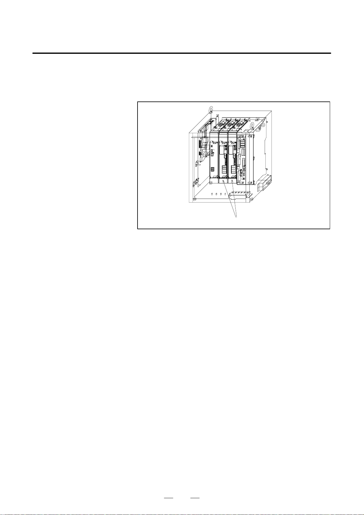
B–81535EN/02
3. TROUBLESHOOTINGMAINTENANCE
(33)SRVO–051 SVAL2 CUER alarm (Group : i Axis : j)
(Explanation) The offset of the current feedback value is abnormally
high.
(Action) Replace the servo amplifier module.
Servo amplifier module
Fig.3.5 (33) SRVO–051 SVAL2 CUER alarm
57
Page 89

3. TROUBLESHOOTING
MAINTENANCE
B–81535EN/02
(34)SRVO–054 DSM Memory Error
(Explanation) An access to the axis control card on the robot control
board memory fails.
(Action) Replace the axis control card.
Robot control board
Servo amplifier module
Axis control card
Fig.3.5 (34) SRVO–054 DSM Memory Error
58
Page 90

B–81535EN/02
3. TROUBLESHOOTINGMAINTENANCE
(35)SRVO–055 SVAL2 FSSB com error 1 (Group : i Axis : j)
(Explanation) A communication error has occurred between the
robot control board and servo amplifier.
(Action 1) Check the communication cable (optical fiber)
between the robot control board and servo amplifier.
Replace it if it is faulty.
(Action 2) Replace the axis control card on the robot control
board.
(Action 3) Replace the servo amplifier module.
Before continuing to the next step, perform a
complete controller back–up to save all your
programs and settings. Failure to perform this could
result in damage to equipment or lost data.
(Action 4) Replace the robot control board.
Robot control board
Servo amplifier module
Axis control card
Fig.3.5 (35) SRVO–055 SVAL2 FSSB com error 1
59
Page 91
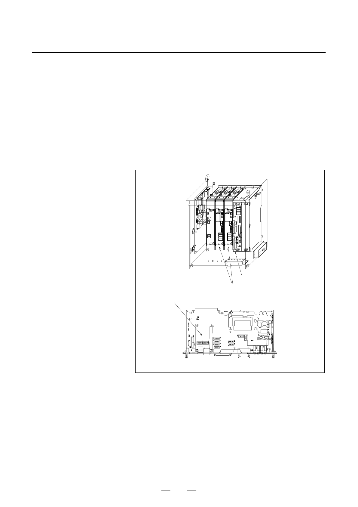
3. TROUBLESHOOTING
MAINTENANCE
B–81535EN/02
(36)SRVO–056 SVAL2 FSSB com error 2 (Group : i Axis : j)
(Explanation) A communication error has occurred between the
robot control board and servo amplifier.
(Action 1) Check the communication cable (optical fiber)
between the robot control board and servo amplifier.
Replace it if it is faulty.
(Action 2) Replace the axis control card on the robot control
board.
(Action 3) Replace the servo amplifier module.
Before continuing to the next step, perform a
complete controller back–up to save all your
programs and settings. Failure to perform this could
result in damage to equipment or lost data.
(Action 4) Replace the robot control board.
Robot control board
Servo amplifier module
Axis control card
Fig.3.5 (36) SRVO–056 SVAL2 FSSB com error 2
60
Page 92
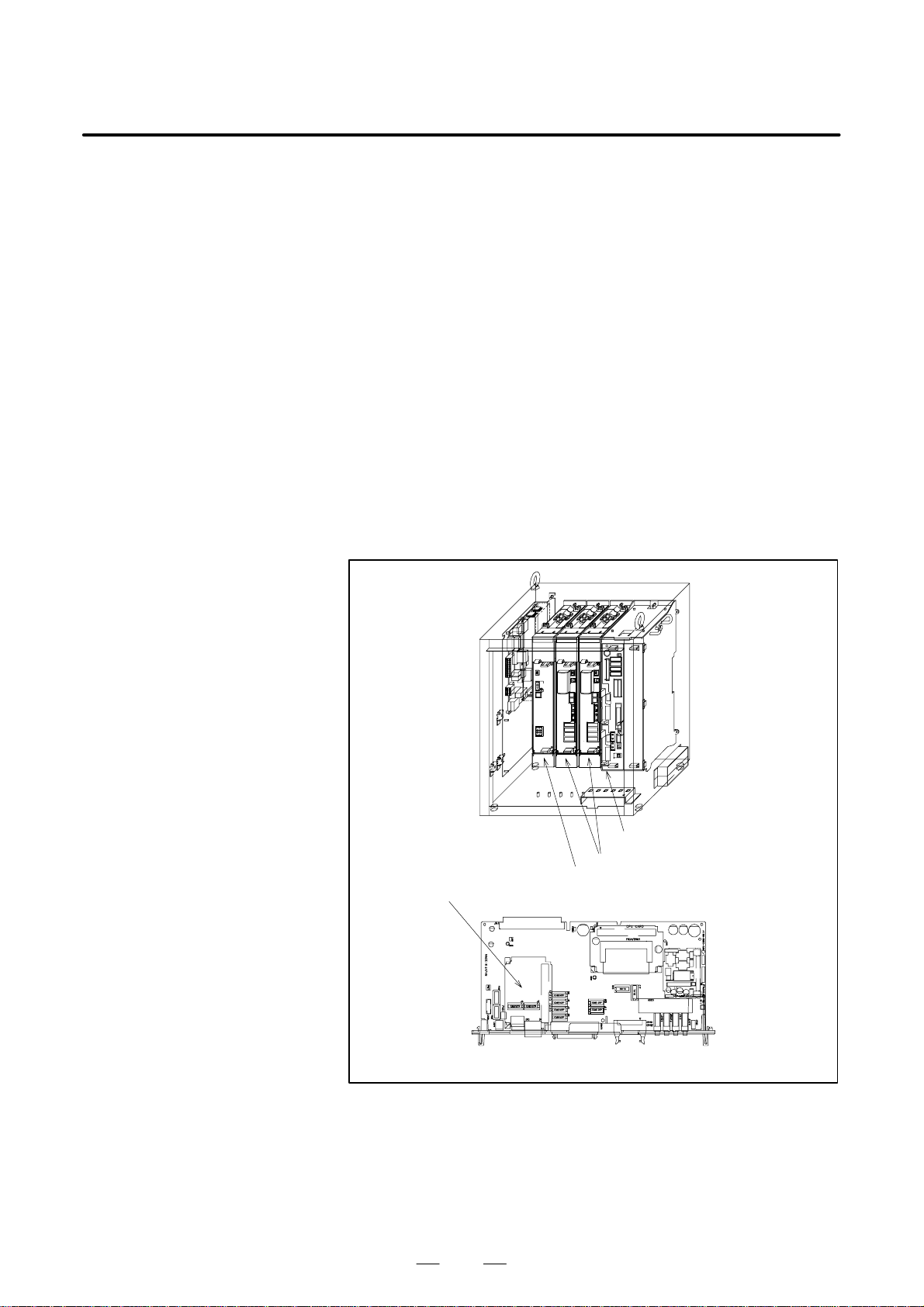
B–81535EN/02
3. TROUBLESHOOTINGMAINTENANCE
(37)SRVO–057 SVAL2 FSSB disconnect (Group : i Axis : j)
(Explanation) Communication was interrupted between the robot
control board and servo amplifier.
(Action 1) Check whether fuse FU1 in the power supply module
unit has blown.
(Action 2) Check whether fuse FU1 in the servo amplifier
module has blown.
(Action 3) Check the communication cable (optical fiber)
between the robot control board and servo amplifier.
Replace it if it is faulty.
(Action 4) Replace the axis control card on the robot control
board.
(Action 5) Replace the power supply module and the servo
amplifier module.
Before continuing to the next step, perform a
complete controller back–up to save all your
programs and settings. Failure to perform this could
result in damage to equipment or lost data.
(Action 6) Replace the robot control board.
(Action 7) Check the RMP cable of robot connection cable.
(+5V ground fault)
Robot control board
Servo amplifier module
Power supply module
Axis control card
Fig.3.5 (37) SRVO–057 SVAL2 FSSB disconnect
61
Page 93
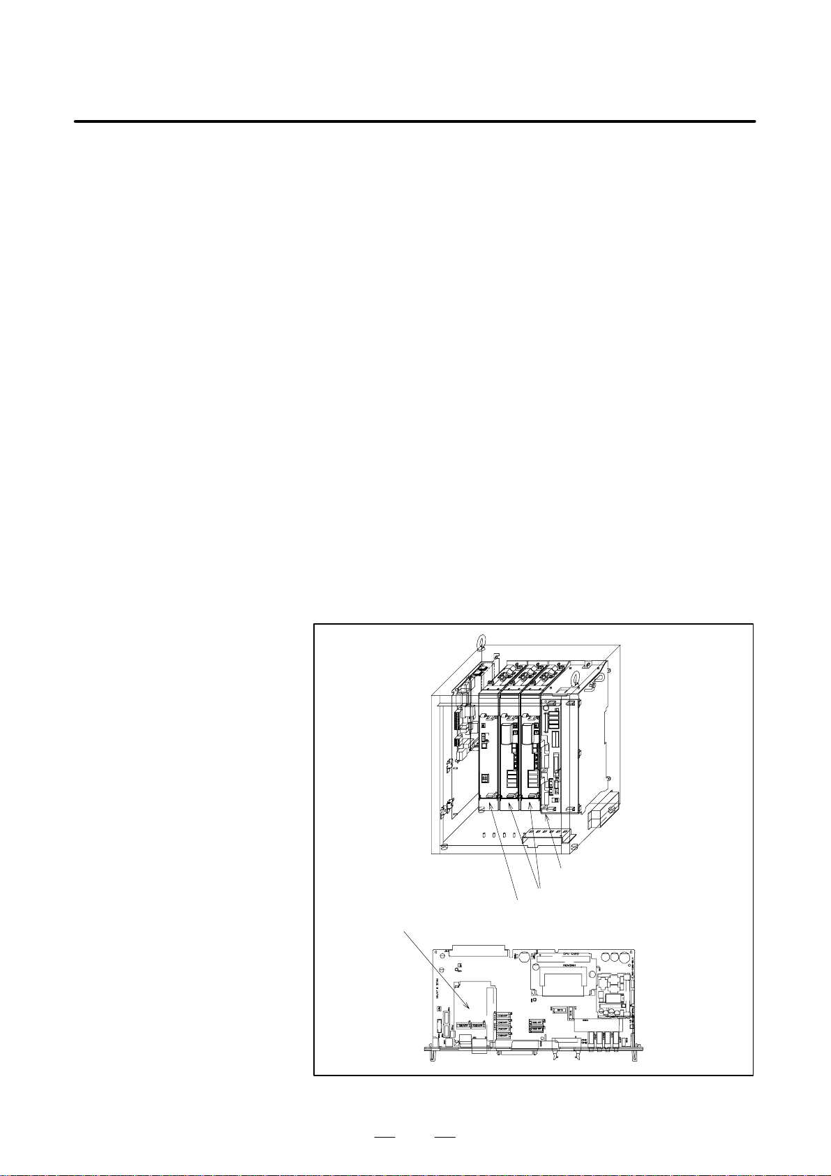
3. TROUBLESHOOTING
MAINTENANCE
B–81535EN/02
(38)SRVO–058 SVAL2 FSSB init error (Group : i Axis : j)
(Explanation) Communication was interrupted between the robot
control board and servo amplifier module.
(Action 1) Check whether fuse FU1 in the power supply module
have blown.
If they have blown, see Section 3.6, “Troubleshooting
for Blown Fuse.”
(Action 2) Check whether seven segment LEDs on the servo
amplifier module are on.
If they are on, perform “Action 4” and all actions that
follow it. If they are not on, perform “Action 3” and
all actions that follow it.
(Action 3) Check whether connector CX1 on the power supply
module is securely connected.
(Action 4) Check the communication cable (optical fiber)
between the robot control board and servo amplifier
module. Replace it if it is faulty.
(Action 5) Replace the axis control card on the robot control
board.
(Action 6) If the seven–segment LED on the servo amplifier
module is glowing, replace the servo amplifier
module. If the seven–segment LED on the servo
amplifier module is not glowing, replace the power
supply module.
Before continuing to the next step, perform a
complete controller back–up to save all your
programs and settings. Failure to perform this could
result in damage to equipment or lost data.
(Action 7) Replace the robot control board.
Robot controll board
Servo amplifier module
Power supply module
Axis control card
Fig.3.5 (38) SRVO–058 SVAL2 FSSB init error
62
Page 94
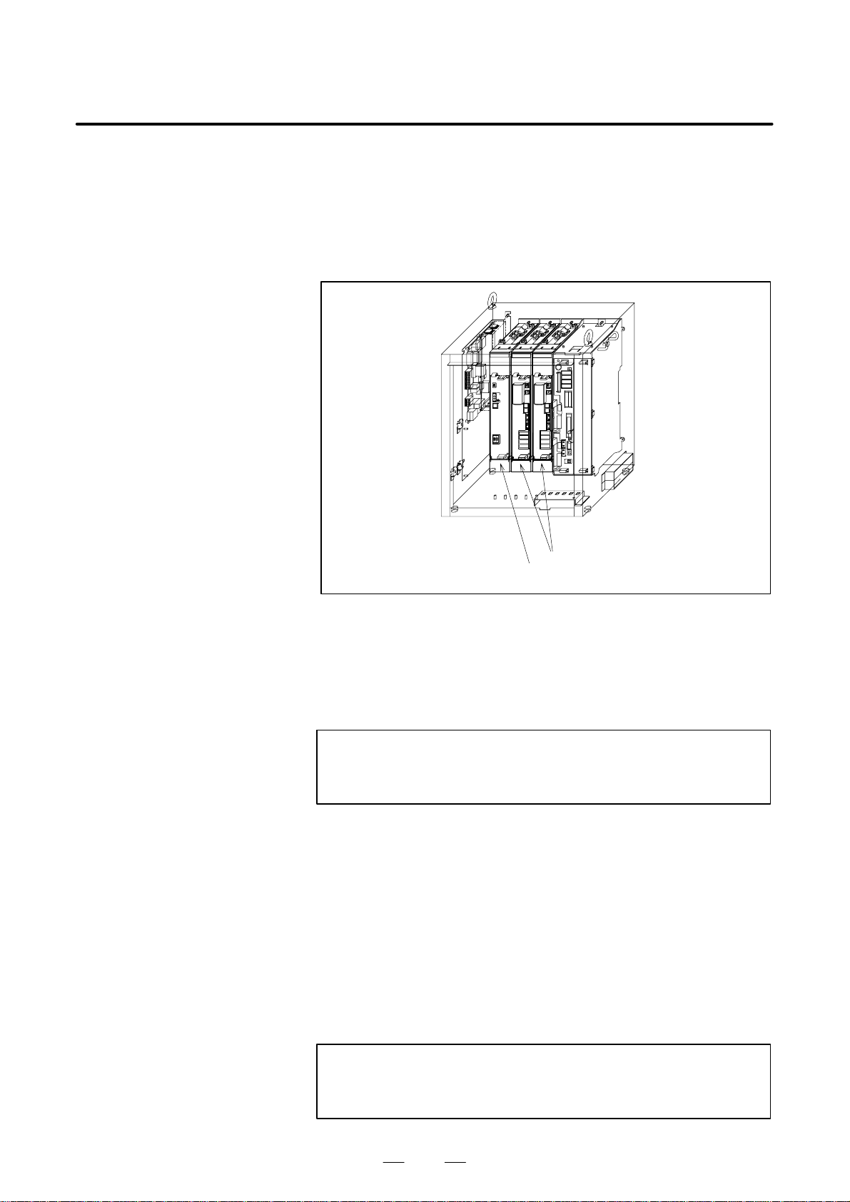
B–81535EN/02
3. TROUBLESHOOTINGMAINTENANCE
(39)SRVO–059 SVAL2 Servo amp init error
(Explanation) Servo amplifier initialzation is failed.
(Action 1) Check all connectors on the PSM and SVM. Make
sure they are installed correctly.
(Action 2) Replace the power supply module and the servo
amplifier module.
Servo amplifier module
Power supply module
Fig.3.5 (39) SRVO–059 SVAL2 Servo amp init error
(40)SRVO–061 SVAL2 CKAL alarm (Group : i Axis : j)
(Explanation) This alarm occurs if the rotation speed count in the
pulse coder is abnormal (abnormal count clock).
(Action) Replace the pulse coder.
NOTE
In this case, perform actions associated with DTERR,
CRCERR, or STBERR first.
(41)SRVO–062 SVAL2 BZAL alarm (Group : i Axis : j)
(Explanation) This alarm occurs if battery for pulse coder
absolute-position backup is empty.
A probable cause is a broken battery cable or no
batteries in the robot.
(Action) Remove the cause of the alarm, set the system
variable ($MCR.$SPC RESET) to TRUE, then turn
the power off and on again. Mastering is required.
(42)SRVO–063 SVAL2 RCAL alarm (Group : i Axis : j)
(Explanation) This alarm occurs if the rotation speed count in the
pulse coder is abnormal (abnormal counter).
(Action) Replace the pulse coder.
NOTE
In this case, perform actions associated with DTERR,
CRCERR, or STBERR first.
63
Page 95

3. TROUBLESHOOTING
MAINTENANCE
B–81535EN/02
(43)SRVO–064 SVAL2 PHAL alarm (Group : i Axis : j)
(Explanation) This alarm occurs if the phase of the pulses generated
in the pulse coder is abnormal.
(Action) Replace the pulse coder.
NOTE
This alarm might accompany the DTERR, CRCERR, or
STBERR alarm. In this case, however, there is no actual
condition for this alarm.
(44)SRVO–065 WARN BLAL alarm (Group : i Axis : j)
(Explanation) The battery voltage for the pulse coder is lower than
the rating.
(Action) Replace the battery.
(If this alarm occurs, turn on the AC power and
replace the battery as soon as possible. A delay in
battery replacement may result in the BZAL alarm
being detected. In this case, the position data will be
lost. Once the position data is lost, mastering will
become necessary.
(45)SRVO–066 SVAL2 CSAL alarm (Group : i Axis : j)
(Explanation) The ROM in the pulse coder is abnormal.
(Action) Replace the pulse coder.
NOTE
This alarm might accompany the DTERR, CRCERR, or
STBERR alarm. In this case, however, there is no actual
condition for this alarm.
(46)SRVO–067 SVAL2 OHAL2 alarm (Group : i Axis : j)
(Explanation) The temperature inside the pulse coder or motor is
abnormally high, and the built–in thermostat has
operated.
(Action 1) Check the operating conditions for the robot and relax
the service conditions.
(Action 2) When power is supplied to the motor after it has
become sufficiently cool, if the alarm still occurs,
replace the motor.
(47)SRVO–068 SVAL2 DTERR alarm (Group : i Axis : j)
(Explanation) The serial pulse coder does not return serial data in
response to a request signal.
–See actions on SRVO–070
(48)SRVO–069 SVAL2 CRCERR alarm (Group : i Axis : j)
(Explanation) The serial data has disturbed during communication.
–See actions on SRVO–070
64
Page 96

B–81535EN/02
3. TROUBLESHOOTINGMAINTENANCE
(49)SRVO–070 SVAL2 STBERR alarm (Group : i Axis : j)
(Explanation) The start and stop bits of the serial data are abnormal.
(Action 1) Make sure that the JF1 to JF3 connector of servo
amplifire module is connected tightly.
(Action 2) Check that the shielding of the robot interconnection
cable (for the pulse coder) and the peripheral equipment
cable is connected securely to the grounding plate.
(Action 3) Check that each unit is grounded securely.
(Action 4) Replace the servo amplifier module.
(Action 5) Replace the pulse coder.
(Action 6) Replace the robot interconnection cable (RMP).
Servo amplifier module
Fig.3.5 (49) SRVO–070 SVAL2 STBERR alarm
(50)SRVO–071 SVAL2 SPHAL alarm (Group : i Axis : j)
(Explanation) The feedback speed is abnormally high.
(Action 1) If this alarm occurs together with the PHAL alarm
(No. 064), this alarm does not correspond to the major
cause of the failure.
(Action 2) Replace the pulse coder.
(51)SRVO–072 SVAL2 PMAL alarm (Group : i Axis : j)
(Explanation) It is likely that the pulse coder is abnormal.
(Action) Replace the pulse coder and remaster the robot.
(52)SRVO–073 SVAL2 CMAL alarm (Group : i Axis : j)
(Explanation) It is likely that the pulse coder is abnormal or the pulse
coder has malfunctioned due to noise.
(Action) Master the robot and enhance the shielding.
(53)SRVO–074 SVAL2 LDAL alarm (Group : i Axis : j)
(Explanation) The LED in the pulse coder is broken.
(Action) Replace the pulse coder, and remaster the robot.
(54)SRVO–075 WARN Pulse not established (Group : i Axis : j)
(Explanation) The absolute position of the pulse coder cannot be
established.
(Action) Reset the alarm, and jog the axis on which the alarm
has occurred until the same alarm will not occur
again. (Jog one motor revolution)
65
Page 97

3. TROUBLESHOOTING
MAINTENANCE
B–81535EN/02
(55)SRVO–076 SVAL1 Tip Stick Detection (Group : i Axis : j)
(Explanation) An excessive disturbance was assumed in servo
software at the start of operation. (An abnormal load
was detected. The cause may be welding.)
(Action 1) Check whether the robot comes into collision with
foreign matter . If a collision occurs, reset the system,
then switch it to the jog feed mode to avoid the
collision.
(Action 2) Check whether the load settings are valid.
(Action 3) Check whether the load weight is within the rated
range. If the weight exceeds the upper limit, decrease
it to the limit.
(Use of the robot with a load exceeding the limit
applied may abnormally increase the assumed
disturbance, resulting in this alarm.)
(Action 4) Check each inter–phase voltage of the three–phase
input (200 VAC) to the power supply module. If the
voltage is 170 VAC or lower, check the input power
supply voltage.
(Action 5) Replace the power supply module and the servo
amplifier module.
Servo amplifier module
Power supply module
Fig.3.5 (60) SRVO–076 SVAL1 Tip Stick Detection
(56)SRVO–081 WARN EROFL alarm (Track enc : i)
(Explanation) The pulse counter for line tracking has overflowed.
(57)SRVO–082 WARN DAL alarm (Track ebc : i)
(Explanation) The line tracking pulse coder has not been connected.
(Action 1) Check the pulse coder connection cable, and replace
it if necessary.
(Action 2) Replace the pulse coder.
(58)SRVO–083 WARN CKAL alarm (Track ebc : i)
(Explanation) This alarm occurs if the rotation speed count in the
pulse coder is abnormal (abnormal count clock).
(Action) See the description about the SRVO–061 CKAL
alarm.
66
Page 98

B–81535EN/02
3. TROUBLESHOOTINGMAINTENANCE
(59)SRVO–084 WARN BZAL alarm (Track enc : i)
(Explanation) This alarm occurs if the backup battery for the absolute
position of the pulse coder has not been connected. See
the description about the BZAL alarm (SRVO–062).
(60)SRVO–085 WARN RCAL alarm (Track ebc : i)
(Explanation) This alarm occurs if the rotation speed count in the
pulse coder is abnormal (abnormal counter).
(Action) See the description about the SRVO–063 RCAL
alarm.
(61)SRVO–086 WARN PHAL alarm (Track enc : i)
(Explanation) This alarm occurs if the phase of pulses generated in
the pulse coder is abnormal. See the description
about the PHAL alarm (SRVO–064).
(62)SRVO–087 WARN BLAL alarm (Track enc : i)
(Explanation) This alarm occurs if the voltage of the backup battery
for the absolute position of the pulse coder is low. S e e
the description about the BLAL alarm (SRVO–065).
(63)SRVO–088 WARN CSAL alarm (Track ebc : i)
(Explanation) The ROM in the pulse coder is abnormal.
(Action) See the description about the SRVO–066 CSAL
alarm.
(64)SRVO–089 WARN OHAL2 alarm (Track enc : i)
(Explanation) The motor has overheated. See the description about
the OHAL2 alarm (SRVO–067).
(65)SRVO–090 WARN DTERR alarm (Track enc : i)
(Explanation) Communication between the pulse coder and line
tracking interface board is abnormal. See the
description about the DTERR alarm (SRVO–068).
(66)SRVO–091 WARN CRCERR alarm (Track enc : i)
(Explanation) Communication between the pulse coder and line
tracking interface board is abnormal. See the
description about the CRCERR alarm (SRVO–069).
(67)SRVO–092 WARN STBERR alarm (Track enc : i)
(Explanation) Communication between the pulse coder and line
tracking interface board is abnormal. See the
description about the STBERR alarm (SRVO–070).
(68)SRVO–093 WARN SPMAL alarm (Track enc : i)
(Explanation) This alarm occurs if the current position data from the
pulse coder is higher than the previous position data.
See the description about the SPHAL alarm
(SRVO–071).
(69)SRVO–094 WARN PMAL alarm (Track enc : i)
(Explanation) It is likely that the pulse coder is abnormal. See the
description about the PMAL alarm (SRVO–072).
(70)SRVO–095 WARN CMAL alarm (Track enc : i)
(Explanation) It is likely that the pulse coder is abnormal or the pulse
coder has malfunctioned due to noise. See the
description about the CMAL alarm (SRVO–073).
(71)SRVO–096 WARN LDAL alarm (Track enc : i)
(Explanation) The LED in the pulse coder is broken. See the
description about the LDAL alarm (SRVO–074).
67
Page 99

3. TROUBLESHOOTING
MAINTENANCE
B–81535EN/02
(72)SRVO–097 WARN Pulse not established (enc : i)
(Explanation) The absolute position of the pulse coder cannot be
established. See the description about (SRVO–075).
Pulse not established.
(73)SRVO–131 SVAL1 LVAL (PSM) alarm (Group : i Axis : j)
(Explanation) The control power supply voltage (for example, +5
V) on the power supply module is abnormally low.
The LED indication on the power supply module is
“6” (LVAL).
(Action 1) Replace the power supply module.
Power supply module
Fig.3.5 (73) SRVO–131 SVAL1 LVAL(PSM) alarm
68
Page 100

B–81535EN/02
3. TROUBLESHOOTINGMAINTENANCE
(74)SRVO–134 SVAL1 DCLVAL (PSM) alarm (Group : i Axis : j)
(Explanation) The DC voltage (DC link voltage) of the main circuit
power supply on the power supply module is
abnormally low. The LED indication on the power
supply module is “4.”
–If this alarm occurs during robot operation:
(Action 1) Check the phase voltage of the three–phase input (200
VAC) to the power supply module. If it is 170 VAC
or lower, check the input power supply voltage.
(Action 2) Replace the power supply module.
–If this alarm occurs before the magnetic contactor (MCC) is turned
on:
(Action 1) Check the emergency stop board and the wiring
between the power supply module and magnetic
contactor (MCC) for an abnormal condition.
(Action 2) Replace the magnetic contactor (MCC).
(Action 3) Replace the emergency stop unit.
(Action 4) Replace the power supply module.
Magnetic contactor
Emergency stop unit
Fig.3.5 (74) SRVO–134 SVAL1 DCLVAL (PSM) alarm
69
Servo amplifier module
Power supply module
 Loading...