

Page 1

<
<
!
R-30iB/R-30iB MATE/R-30iB PLUS CONTROLLER
>
Basic Interference Check and
Intelligent Interference Check
OPERATOR’S MANUAL
Version 8.20 and later
MAROBBI8204121E REV F
©2013-2019 FANUC America Corporation
Page 2

Copyrights and Trademarks
This new publication contains proprietary information of FANUC America
Corporation furnished for customer use only. No other uses are authorized without
the express written permission of FANUC America Corporation.
The descriptions and specifications contained in this manual were in effect at the
time this manual was approved for printing. FANUC America Corporation,
hereinafter referred to as FANUC, reserves the right to discontinue models at any
time or to change specifications or design without notice and without incurring
obligations.
FANUC manuals present descriptions, specifications, drawings, schematics, bills of
material, parts, connections and/or procedures for installing, disassembling,
connecting, operating and programming FANUC products and/or systems. Such
systems consist of robots, extended axes, robot controllers, application software, the
KAREL® programming language, INSIGHT® vision equipment, and special tools.
FANUC recommends that only persons who have been trained in one or more
approved FANUC Training Course(s) be permitted to install, operate, use, perform
procedures on, repair, and/or maintain FANUC products and/or systems and their
respective components. Approved training necessitates that the courses selected be
relevant to the type of system installed and application performed at the customer
site.
WARNING
This equipment generates, uses, and can radiate
radiofrequency energy and if not installed and used in
accordance with the instruction manual, may cause
interference to radio communications. As temporarily
permitted by regulation, it has not been tested for
compliance with the limits for Class A computing devices
pursuant to Subpart J and Part 15 of FCC Rules, which are
designed to provide reasonable protection against such
interference. Operation of the equipment in a residential
area is likely to cause interference, in which case the user,
at his own expense, will be required to take whatever
measure may be required to correct the interference.
Page 3

FANUC conducts courses on its systems and products on a regularly scheduled
basis at the company's world headquarters in Rochester Hills, Michigan. For
additional information contact
FANUC America Corporation
Training Department
3900 W. Hamlin Road
Rochester Hills, Michigan 48309-3253
www.fanucamerica.com
For customer assistance, including Technical Support, Service, Parts & Part Repair,
and Marketing Requests, contact the Customer Resource Center, 24 hours a day, at
888-FANUC-US (888-326-8287).
Send your comments and suggestions about this manual to:
product.documentation@fanucamerica.com
Copyright © 2019 by FANUC America Corporation
All Rights Reserved
The information illustrated or contained herein is not to be
reproduced, copied, downloaded, translated into another language, published in any
physical or electronic format, including internet, or transmitted in whole or in part
in any way without the prior written consent of FANUC America Corporation.
AccuStat®, ArcTool®, iRVision®, KAREL®, PaintTool®, PalletTool®,
SOCKETS®, SpotTool®, SpotWorks®, and TorchMate® are Registered
Trademarks of FANUC.
FANUC reserves all proprietary rights, including but not
limited to trademark and trade name rights, in the following names:
AccuAir™, AccuCal™, AccuChop™, AccuFlow™, AccuPath™,
AccuSeal™, ARC Mate™, ARC Mate Sr.™, ARC Mate System 1™,
ARC Mate System 2™, ARC Mate System 3™, ARC Mate System 4™,
ARC Mate System 5™, ARCWorks Pro™, AssistTool™, AutoNormal™,
AutoTCP™, BellTool™, BODYWorks™, Cal Mate™, Cell Finder™,
Center Finder™, Clean Wall™, DualARM™, iRProgrammer™, LR Tool™,
MIG Eye™, MotionParts™, MultiARM™, NoBots™, Paint
Stick™, PaintPro™, PaintTool 100™, PAINTWorks™, PAINTWorks
II™, PAINTWorks III™, PalletMate™, PalletMate PC™,
PalletTool PC™, PayloadID™, RecipTool™, RemovalTool™,
Robo Chop™, Robo Spray™, S-420i™, S-430i™, ShapeGen™,
SoftFloat™, SOFT PARTS™, SpotTool+™, SR Mate™, SR
ShotTool™, SureWeld™, SYSTEM R-J2 Controller™, SYSTEM R-J3
Controller™, SYSTEM R-J3iB Controller™, SYSTEM R-J3iC Controller™,
SYSTEM R-30iA Controller™, SYSTEM R-30iA Mate Controller™, SYSTEM R30iB Controller™, SYSTEM R-30iB Mate Controller™, SYSTEM R-30iB Plus
Controller™, SYSTEM R-30iB Mate Plus Controller™, TCP Mate™,
TorchMate™, TripleARM™, TurboMove™, visLOC™, visPRO-3D™,
visTRAC™, WebServer™, WebTP™, and YagTool™.
©FANUC CORPORATION 2019
x No part of this manual may be reproduced in any form.
x All specifications and designs are subject to change without notice.
Page 4

Patents
One or more of the following U.S. patents might be related to the FANUC products
described in this manual.
FANUC America Corporation Patent List
4,630,567 4,639,878 4,707,647 4,708,175 4,708,580 4,942,539 4,984,745 5,238,029
5,239,739 5,272,805 5,293,107 5,293,911 5,331,264 5,367,944 5,373,221 5,421,218
5,434,489 5,644,898 5,670,202 5,696,687 5,737,218 5,823,389 5,853,027 5,887,800
5,941,679 5,959,425 5,987,726 6,059,092 6,064,168 6,070,109 6,086,294 6,122,062
6,147,323 6,204,620 6,243,621 6,253,799 6,285,920 6,313,595 6,325,302 6,345,818
6,356,807 6,360,143 6,378,190 6,385,508 6,425,177 6,477,913 6,490,369 6,518,980
6,540,104 6,541,757 6,560,513 6,569,258 6,612,449 6,703,079 6,705,361 6,726,773
6,768,078 6,845,295 6,945,483 7,149,606 7,149,606 7,211,978 7,266,422 7,399,363
FANUC CORPORATION Patent List
4,571,694 4,626,756 4,700,118 4,706,001 4,728,872 4,732,526 4,742,207 4,835,362
4,894,596 4,899,095 4,920,248 4,931,617 4,934,504 4,956,594 4,967,125 4,969,109
4,970,370 4,970,448 4,979,127 5,004,968 5,006,035 5,008,834 5,063,281 5,066,847
5,066,902 5,093,552 5,107,716 5,111,019 5,130,515 5,136,223 5,151,608 5,170,109
5,189,351 5,267,483 5,274,360 5,292,066 5,300,868 5,304,906 5,313,563 5,319,443
5,325,467 5,327,057 5,329,469 5,333,242 5,337,148 5,371,452 5,375,480 5,418,441
5,432,316 5,440,213 5,442,155 5,444,612 5,449,875 5,451,850 5,461,478 5,463,297
5,467,003 5,471,312 5,479,078 5,485,389 5,485,552 5,486,679 5,489,758
5,493,192 5,504,766 5,511,007 5,520,062 5,528,013 5,532,924 5,548,194 5,552,687
5,558,196 5,561,742 5,570,187 5,570,190 5,572,103 5,581,167 5,582,750 5,587,635
5,600,759 5,608,299 5,608,618 5,624,588 5,630,955 5,637,969 5,639,204 5,641,415
5,650,078 5,658,121 5,668,628 5,687,295 5,691,615 5,698,121 5,708,342 5,715,375
5,719,479 5,727,132 5,742,138 5,742,144 5,748,854 5,749,058 5,760,560 5,773,950
5,783,922 5,799,135 5,812,408 5,841,257 5,845,053 5,872,894 5,887,122 5,911,892
5,912,540 5,920,678 5,937,143 5,980,082 5,983,744 5,987,591 5,988,850 6,023,044
6,032,086 6,040,554 6,059,169 6,088,628 6,097,169 6,114,824 6,124,693
6,140,788 6,141,863 6,157,155 6,160,324 6,163,124 6,177,650 6,180,898 6,181,096
6,188,194 6,208,105 6,212,444 6,219,583 6,226,181 6,236,011 6,236,896 6,250,174
6,278,902 6,279,413 6,285,921 6,298,283 6,321,139 6,324,443 6,328,523 6,330,493
6,340,875 6,356,671 6,377,869 6,382,012 6,384,371 6,396,030 6,414,711 6,424,883
6,431,018 6,434,448 6,445,979 6,459,958 6,463,358 6,484,067 6,486,629 6,507,165
6,654,666 6,665,588 6,680,461 6,696,810 6,728,417 6,763,284 6,772,493 6,845,296
6,853,881 6,888,089 6,898,486 6,917,837 6,928,337 6,965,091 6,970,802 7,038,165
7,069,808 7,084,900 7,092,791 7,133,747 7,143,100 7,149,602 7,131,848
7,161,321 7,171,041 7,174,234 7,173,213 7,177,722 7,177,439 7,181,294 7,181,313
7,280,687 7,283,661 7,291,806 7,299,713 7,315,650 7,324,873 7,328,083 7,330,777
7,333,879 7,355,725 7,359,817 7,373,220 7,376,488 7,386,367 7,464,623 7,447,615
7,445,260 7,474,939 7,486,816 7,495,192 7,501,778 7,502,504 7,508,155 7,512,459
7,525,273 7,526,121
Page 5

Conventions
WARNING
Information appearing under the "WARNING" caption concerns the protection of
personnel. It is boxed and bolded to set it apart from the surrounding text.
CAUTION
Information appearing under the "CAUTION" caption concerns the protection of
equipment, software, and data. It is boxed and bolded to set it apart from the
surrounding text.
Note Information appearing next to NOTE concerns related information or useful hints.
Page 6

Page 7

Safety
FANUC America Corporation is not and does not represent itself as an expert in safety
systems, safety equipment, or the specific safety aspects of your company and/or its work
force. It is the responsibility of the owner, employer, or user to take all necessary steps to
guarantee the safety of all personnel in the workplace.
The appropriate level of safety for your application and installation can be best determined
by safety system professionals. FANUC America Corporation therefore, recommends that
each customer consult with such professionals in order to provide a workplace that allows
for the safe application, use, and operation of FANUC America Corporation systems.
According to the industry standard ANSI/RIA R15-06, the owner or user is advised to
consult the standards to ensure compliance with its requests for Robotics System design,
usability, operation, maintenance, and service. Additionally, as the owner, employer, or user
of a robotic system, it is your responsibility to arrange for the training of the operator of a
robot system to recognize and respond to known hazards associated with your robotic
system and to be aware of the recommended operating procedures for your particular
application and robot installation.
Ensure that the robot being used is appropriate for the application. Robots used in classified
(hazardous) locations must be certified for this use.
FANUC America Corporation therefore, recommends that all personnel who intend to
operate, program, repair, or otherwise use the robotics system be trained in an approved
FANUC America Corporation training course and become familiar with the proper operation
of the system. Persons responsible for programming the system–including the design,
implementation, and debugging of application programs–must be familiar with the
recommended programming procedures for your application and robot installation.
The following guidelines are provided to emphasize the importance of safety in the
workplace.
CONSIDERING SAFETY FOR YOUR ROBOT INSTALLATION
Safety is essential whenever robots are used. Keep in mind the following factors with regard
to safety:
x The safety of people and equipment
x Use of safety enhancing devices
x Techniques for safe teaching and manual operation of the robot(s)
x Techniques for safe automatic operation of the robot(s)
x Regular scheduled inspection of the robot and workcell
x Proper maintenance of the robot
s-1
Page 8

Safety
Keeping People Safe
The safety of people is always of primary importance in any situation. When applying
safety measures to your robotic system, consider the following:
x External devices
x Robot(s)
x Tooling
x Workpiece
Using Safety Enhancing Devices
Always give appropriate attention to the work area that surrounds the robot. The safety of
the work area can be enhanced by the installation of some or all of the following devices:
x Safety fences, barriers, or chains
x Light curtains
x Interlocks
x Pressure mats
x Floor markings
x Warning lights
x Mechanical stops
x EMERGENCY STOP buttons
x DEADMAN switches
Setting Up a Safe Workcell
A safe workcell is essential to protect people and equipment. Observe the following
guidelines to ensure that the workcell is set up safely. These suggestions are intended to
supplement and not replace existing federal, state, and local laws, regulations, and guidelines
that pertain to safety.
x Sponsor your personnel for training in approved FANUC America Corporation training
course(s) related to your application. Never permit untrained personnel to operate the
robots.
x Install a lockout device that uses an access code to prevent unauthorized persons from
operating the robot.
x Use anti–tie–down logic to prevent the operator from bypassing safety measures.
x Arrange the workcell so the operator faces the workcell and can see what is going on
inside the cell.
x Clearly identify the work envelope of each robot in the system with floor markings,
signs, and special barriers. The work envelope is the area defined by the maximum
motion range of the robot, including any tooling attached to the wrist flange that extend
this range.
x Position all controllers outside the robot work envelope.
x Never rely on software or firmware based controllers as the primary safety element
unless they comply with applicable current robot safety standards.
x Mount an adequate number of EMERGENCY STOP buttons or switches within easy
reach of the operator and at critical points inside and around the outside of the workcell.
s-2
Page 9

Safety
x Install flashing lights and/or audible warning devices that activate whenever the robot is
operating, that is, whenever power is applied to the servo drive system. Audible
warning devices shall exceed the ambient noise level at the end–use application.
x Wherever possible, install safety fences to protect against unauthorized entry by
personnel into the work envelope.
x Install special guarding that prevents the operator from reaching into restricted areas of
the work envelope.
x Use interlocks.
x Use presence or proximity sensing devices such as light curtains, mats, and capacitance
and vision systems to enhance safety.
x Periodically check the safety joints or safety clutches that can be optionally installed
between the robot wrist flange and tooling. If the tooling strikes an object, these devices
dislodge, remove power from the system, and help to minimize damage to the tooling
and robot.
x Make sure all external devices are properly filtered, grounded, shielded, and suppressed
to prevent hazardous motion due to the effects of electro–magnetic interference (EMI),
radio frequency interference (RFI), and electro–static discharge (ESD).
x Make provisions for power lockout/tagout at the controller.
x Eliminate pinch points. Pinch points are areas where personnel could get trapped
between a moving robot and other equipment.
x Provide enough room inside the workcell to permit personnel to teach the robot and
perform maintenance safely.
x Program the robot to load and unload material safely.
x If high voltage electrostatics are present, be sure to provide appropriate interlocks,
warning, and beacons.
x If materials are being applied at dangerously high pressure, provide electrical interlocks
for lockout of material flow and pressure.
Staying Safe While Teaching or Manually Operating the Robot
Advise all personnel who must teach the robot or otherwise manually operate the robot to
observe the following rules:
x Never wear watches, rings, neckties, scarves, or loose clothing that could get caught in
moving machinery.
x Know whether or not you are using an intrinsically safe teach pendant if you are
working in a hazardous environment.
x Before teaching, visually inspect the robot and work envelope to make sure that no
potentially hazardous conditions exist. The work envelope is the area defined by the
maximum motion range of the robot. These include tooling attached to the wrist flange
that extends this range.
x The area near the robot must be clean and free of oil, water, or debris. Immediately
report unsafe working conditions to the supervisor or safety department.
x FANUC America Corporation recommends that no one enter the work envelope of a
robot that is on, except for robot teaching operations. However, if you must enter the
work envelope, be sure all safeguards are in place, check the teach pendant DEADMAN
switch for proper operation, and place the robot in teach mode. Take the teach pendant
with you, turn it on, and be prepared to release the DEADMAN switch. Only the person
with the teach pendant should be in the work envelope.
s-3
Page 10
Safety
WARNING
Never bypass, strap, or otherwise deactivate a safety device, such as a limit switch,
for any operational convenience. Deactivating a safety device is known to have
resulted in serious injury and death.
x Know the path that can be used to escape from a moving robot; make sure the escape
path is never blocked.
x Isolate the robot from all remote control signals that can cause motion while data is
being taught.
x Test any program being run for the first time in the following manner:
WARNING
Stay outside the robot work envelope whenever a program is being run. Failure to do
so can result in injury.
- Using a low motion speed, single step the program for at least one full cycle.
- Using a low motion speed, test run the program continuously for at least one full
cycle.
- Using the programmed speed, test run the program continuously for at least one
full cycle.
x Make sure all personnel are outside the work envelope before running production.
Staying Safe During Automatic Operation
Advise all personnel who operate the robot during production to observe the following rules:
x Make sure all safety provisions are present and active.
x Know the entire workcell area. The workcell includes the robot and its work envelope,
plus the area occupied by all external devices and other equipment with which the robot
interacts.
x Understand the complete task the robot is programmed to perform before initiating
automatic operation.
x Make sure all personnel are outside the work envelope before operating the robot.
x Never enter or allow others to enter the work envelope during automatic operation of the
robot.
x Know the location and status of all switches, sensors, and control signals that could
cause the robot to move.
x Know where the EMERGENCY STOP buttons are located on both the robot control and
external control devices. Be prepared to press these buttons in an emergency.
x Never assume that a program is complete if the robot is not moving. The robot could be
waiting for an input signal that will permit it to continue its activity.
x If the robot is running in a pattern, do not assume it will continue to run in the same
pattern.
s-4
Page 11

Safety
x Never try to stop the robot, or break its motion, with your body. The only way to stop
robot motion immediately is to press an EMERGENCY STOP button located on the
controller panel, teach pendant, or emergency stop stations around the workcell.
Staying Safe During Inspection
When inspecting the robot, be sure to
x Turn off power at the controller.
x Lock out and tag out the power source at the controller according to the policies of your
plant.
x Turn off the compressed air source and relieve the air pressure.
x If robot motion is not needed for inspecting the electrical circuits, press the
EMERGENCY STOP button on the operator panel.
x Never wear watches, rings, neckties, scarves, or loose clothing that could get caught in
moving machinery.
x If power is needed to check the robot motion or electrical circuits, be prepared to press
the EMERGENCY STOP button, in an emergency.
x Be aware that when you remove a servomotor or brake, the associated robot arm will fall
if it is not supported or resting on a hard stop. Support the arm on a solid support before
you release the brake.
Staying Safe During Maintenance
When performing maintenance on your robot system, observe the following rules:
x Never enter the work envelope while the robot or a program is in operation.
x Before entering the work envelope, visually inspect the workcell to make sure no
potentially hazardous conditions exist.
x Never wear watches, rings, neckties, scarves, or loose clothing that could get caught in
moving machinery.
x Consider all or any overlapping work envelopes of adjoining robots when standing in a
work envelope.
x Test the teach pendant for proper operation before entering the work envelope.
x If it is necessary for you to enter the robot work envelope while power is turned on, you
must be sure that you are in control of the robot. Be sure to take the teach pendant with
you, press the DEADMAN switch, and turn the teach pendant on. Be prepared to
release the DEADMAN switch to turn off servo power to the robot immediately.
x Whenever possible, perform maintenance with the power turned off. Before you open
the controller front panel or enter the work envelope, turn off and lock out the 3–phase
power source at the controller.
x Be aware that when you remove a servomotor or brake, the associated robot arm will fall
if it is not supported or resting on a hard stop. Support the arm on a solid support before
you release the brake.
s-5
Page 12
Safety
WARNING
Lethal voltage is present in the controller WHENEVER IT IS CONNECTED to a
power source. Be extremely careful to avoid electrical shock. HIGH VOLTAGE IS
PRESENT at the input side whenever the controller is connected to a power
source. Turning the disconnect or circuit breaker to the OFF position removes
power from the output side of the device only.
x Release or block all stored energy. Before working on the pneumatic system, shut off
the system air supply and purge the air lines.
x Isolate the robot from all remote control signals. If maintenance must be done when the
power is on, make sure the person inside the work envelope has sole control of the robot.
The teach pendant must be held by this person.
x Make sure personnel cannot get trapped between the moving robot and other equipment.
Know the path that can be used to escape from a moving robot. Make sure the escape
route is never blocked.
x Use blocks, mechanical stops, and pins to prevent hazardous movement by the robot.
Make sure that such devices do not create pinch points that could trap personnel.
WARNING
Do not try to remove any mechanical component from the robot before thoroughly
reading and understanding the procedures in the appropriate manual. Doing so can
result in serious personal injury and component destruction.
x Be aware that when you remove a servomotor or brake, the associated robot arm will fall
if it is not supported or resting on a hard stop. Support the arm on a solid support before
you release the brake.
x When replacing or installing components, make sure dirt and debris do not enter the
system.
x Use only specified parts for replacement. To avoid fires and damage to parts in the
controller, never use nonspecified fuses.
x Before restarting a robot, make sure no one is inside the work envelope; be sure that the
robot and all external devices are operating normally.
KEEPING MACHINE TOOLS AND EXTERNAL DEVICES SAFE
Certain programming and mechanical measures are useful in keeping the machine tools and
other external devices safe. Some of these measures are outlined below. Make sure you
know all associated measures for safe use of such devices.
Programming Safety Precautions
Implement the following programming safety measures to prevent damage to machine tools
and other external devices.
x Back–check limit switches in the workcell to make sure they do not fail.
x Implement ‘‘failure routines” in programs that will provide appropriate robot actions if
an external device or another robot in the workcell fails.
s-6
Page 13

Safety
x Use handshaking protocol to synchronize robot and external device operations.
x Program the robot to check the condition of all external devices during an operating
cycle.
Mechanical Safety Precautions
Implement the following mechanical safety measures to prevent damage to machine tools
and other external devices.
x Make sure the workcell is clean and free of oil, water, and debris.
x Use DCS (Dual Check Safety), software limits, limit switches, and mechanical hardstops
to prevent undesired movement of the robot into the work area of machine tools and
external devices.
s-7
Page 14

Safety
KEEPING THE ROBOT SAFE
Observe the following operating and programming guidelines to prevent damage to the
robot.
Operating Safety Precautions
The following measures are designed to prevent damage to the robot during operation.
x Use a low override speed to increase your control over the robot when jogging the robot.
x Visualize the movement the robot will make before you press the jog keys on the teach
pendant.
x Make sure the work envelope is clean and free of oil, water, or debris.
x Use circuit breakers to guard against electrical overload.
Programming Safety Precautions
The following safety measures are designed to prevent damage to the robot during
programming:
x Establish interference zones to prevent collisions when two or more robots share a work
area.
x Make sure that the program ends with the robot near or at the home position.
x Be aware of signals or other operations that could trigger operation of tooling resulting
in personal injury or equipment damage.
x In dispensing applications, be aware of all safety guidelines with respect to the
dispensing materials.
NOTE: Any deviation from the methods and safety practices described in this manual must
conform to the approved standards of your company. If you have questions, see your
supervisor.
s-8
Page 15

MAROBBI8204121E REV F 1 TABLE OF CONTENTS
TABLE OF CONTENTS
1 PREFACE ..................................................................................................................................... 1
2 OUTLINE ...................................................................................................................................... 4
3 SETTINGS .................................................................................................................................... 6
3.1 NETWORK ....................................................................................................................................... 6
3.1.1 Wiring and Connection ............................................................................................................. 6
3.1.1.1 Environment ...................................................................................................................... 6
3.1.1.2 Notes ................................................................................................................................... 8
3.1.2 Settings ...................................................................................................................................... 9
3.1.2.1 Setting the host names, Internet (IP) addresses, and subnet mask ............................. 9
3.1.2.2 Setting full duplex mode (for each robot controller) ..................................................... 10
3.1.2.3 Setting full duplex mode (for the Ethernet switch) ...................................................... 10
3.1.3 Checking the Network-Related Settings .............................................................................. 10
3.1.4 Configuring RIPE automatically ........................................................................................... 11
3.1.5 Configuring RIPE with ROSIPCFG.XML ............................................................................ 13
3.2 CALIBRATION .............................................................................................................................. 14
3.2.1 Calibration Data ..................................................................................................................... 16
3.2.2 Setting Calibration Data ........................................................................................................ 17
3.2.2.1 Direct input method ........................................................................................................ 20
3.2.2.2 Three point method ......................................................................................................... 22
3.2.3 Troubleshooting ...................................................................................................................... 27
3.3 SETTING MODELS ...................................................................................................................... 27
3.3.1 Definition of Elements ............................................................................................................ 27
3.3.2 Setting Up a Hand Model....................................................................................................... 32
3.3.2.1 Hand Modeling Example ................................................................................................ 33
3.3.2.2 Add Comment To A Hand Model ................................................................................... 34
3.3.2.3 Edit Geometric Elements For A Hand Model ............................................................... 35
3.3.2.4 Setting Detail Data For A Hand Geometric Element ................................................... 37
3.3.2.5 Mapping A Hand With A Tool Number ......................................................................... 38
3.3.2.6 Clear A Hand Model ........................................................................................................ 40
3.3.3 Setting Up A Fixture Model ................................................................................................... 40
3.3.3.1 Fixture Model Example .................................................................................................. 41
3.3.3.2 Enter A Comment ............................................................................................................ 42
3.3.3.3 Select Reference Robot Group ........................................................................................ 44
3.3.3.4 Create Geometric Model ................................................................................................. 45
3.3.3.5 Setting Fixture Elements ............................................................................................... 47
Page 16

TABLE OF CONTENTS MAROBBI8204121E REV F
3.3.3.6 Clearing a Fixture Model ................................................................................................ 49
3.3.4 Setting Up A Robot Model ...................................................................................................... 49
3.3.4.1 View Robot List ................................................................................................................ 49
3.3.4.2 View Geometric Elements of A Robot model ................................................................. 51
3.3.4.3 View/Edit Detail Geometric Element ............................................................................ 53
3.3.5 Using 4D Graphics In Model Setup Menus .......................................................................... 55
3.3.5.1 Using 4D Graphics In Hand Model Setup Menu .......................................................... 56
3.3.5.2 Using 4D Graphics In Fixture Model Setup Menu ....................................................... 58
3.3.5.3 Using 4D Graphics In Robot Model Setup Menu .......................................................... 62
3.3.5.4 Data Storage of The Geometric Elements ..................................................................... 64
3.3.6 Copying Models ....................................................................................................................... 65
3.3.6.1 Copy From DCS ............................................................................................................... 65
3.3.6.2 Copy from IIC .................................................................................................................. 69
3.3.6.3 Copy From/To XML ......................................................................................................... 73
3.4 SETTING INTERFERENCE CHECK COMBINATIONS ......................................................... 75
3.4.1 Setting a combination of models ............................................................................................ 75
3.4.1.1 Setting up combination for Robot + Hand ..................................................................... 79
3.4.1.2 Setting up combination for Fixture ................................................................................ 83
3.4.1.3 Setting up combination for Critical Zone ...................................................................... 86
3.4.1.4 Setting up combination for Virtual Fence ..................................................................... 89
3.4.1.5 Setting up combination for DO Only ............................................................................. 91
3.4.1.6 PLC DIN ........................................................................................................................... 93
3.4.2 Enabling combinations ........................................................................................................... 95
3.5 SETTING OTHER PARAMETERS .............................................................................................. 96
3.6 MODEL DATA STORAGE DESTINATION ................................................................................ 98
3.7 ENABLING DSP COMPUTATION ............................................................................................. 98
3.8 APPROACH WAIT COMBINATIONS ......................................................................................... 98
3.8.1 Approach Wait Combination List Screen ............................................................................. 99
3.8.1.1 Setting items .................................................................................................................. 100
3.8.2 Approach Wait Combination Detail Screen ........................................................................ 102
3.8.2.1 Settings ........................................................................................................................... 104
3.9 SETTING DEADLOCK PREVENTION .................................................................................... 105
3.9.1 Deadlock Prevention Setup Menu ....................................................................................... 107
3.9.2 Deadlock Prevention Schedule List..................................................................................... 108
3.9.3 Deadlock Prevention Schedule Detail ................................................................................. 108
3.9.4 Deadlock Prevention Limitations ........................................................................................ 112
3.10 ROBOT BYPASS FUNCTION ................................................................................................ 113
3.10.1 Robot Bypass Setup Menu ................................................................................................... 113
xvi
Page 17

MAROBBI8204121E REV F TABLE OF CONTENTS
3.10.2 Robot Bypass Runtime Check.............................................................................................. 115
3.10.3 Robot Bypass Limitations .................................................................................................... 115
3.11
3.11.1
LINE TRACKING SUPPORT ............................................................................................ 116
Line Tracking Support Limitations ............................................................................... 116
4 PROGRAM INSTRUCTIONS .................................................................................................... 117
4.1 APPROACH STOP ENABLE/DISABLE INSTRUCTION ....................................................... 117
4.1.1 Details .................................................................................................................................... 117
4.1.2 Sample Program ................................................................................................................... 118
4.1.3 Reverse Program Execution ................................................................................................. 118
4.1.4 Notes ...................................................................................................................................... 119
4.2 APPROACH WAIT ENABLE/DISABLE INSTRUCTION ....................................................... 121
4.2.1 Details .................................................................................................................................... 121
4.2.2 Sample Program ................................................................................................................... 122
4.2.3 Reverse Program Execution ................................................................................................. 123
4.2.4 Disabling Deceleration Stop Based on Approach Wait ..................................................... 124
4.2.5 Example of Use ..................................................................................................................... 124
4.2.6 Deadlock Caused by the Approach Wait Function ............................................................ 126
4.2.7 Notes ...................................................................................................................................... 126
4.3 APPROACH RATE INSTRUCTION .......................................................................................... 128
4.3.1 Details .................................................................................................................................... 128
4.3.2 Reverse Program Execution ................................................................................................. 129
4.4 COMB PAIR ENABLE INSTRUCTION .................................................................................... 129
4.5 COMB PAIR DISABLE INSTRUCTION ................................................................................... 129
4.6 MULTI ARM SYNCHRONIZATION INSTRUCTIONS ........................................................... 129
4.6.1 Setup ...................................................................................................................................... 130
4.6.2 Usage of the function ............................................................................................................ 132
4.6.2.1 WaitZone[ ] / SyncZone[ ] .............................................................................................. 132
4.6.2.2 EnterZone[ ] / ExitZone[ ] ............................................................................................. 133
4.6.3 Macros Associated with the Instructions ............................................................................ 134
4.6.4 Input parameters for the Macros ........................................................................................ 135
4.6.4.1 For WaitZone[ ] .............................................................................................................. 135
4.6.4.2 For SyncZone[ ] .............................................................................................................. 136
4.6.4.3 For EnterZone[ ] ............................................................................................................ 136
4.6.4.4 For ExitZone[ ] ............................................................................................................... 137
4.6.5 Insert/Edit the stand-alone instructions in a TPE program ............................................. 137
4.6.5.1 WaitZone[ ] or SyncZone[ ]: ........................................................................................... 138
4.6.5.2 EnterZone[ ] or ExitZone[ ] ........................................................................................... 141
4.6.6 Abort program ....................................................................................................................... 143
xvii
Page 18

TABLE OF CONTENTS MAROBBI8204121E REV F
4.6.7 Reset ...................................................................................................................................... 144
4.6.8 Limitations ............................................................................................................................ 144
5 INTERFERENCE STATUS MENU ............................................................................................ 146
5.1 Interference Check Status Main Menu ...................................................................................... 147
5.2 Interference Check Combination Status .................................................................................... 149
5.3 Approach Wait Status Menu ....................................................................................................... 151
6 INTERFERENCE CHECK 4D GRAPHICS ................................................................................ 155
6.1 IIC/BIC 4D Cell Display .............................................................................................................. 155
6.2 IIC/BIC 4D Display In Interference Check Menu ..................................................................... 158
6.2.1 4D Graphics in Combination Check Menu ......................................................................... 163
6.3 IIC Dead Lock Prevention 4D Display In Editor Menu ............................................................ 166
6.4 Automatic Cell Frame Update .................................................................................................... 171
7 IIC FOR ARC (R872) .........................................................................................................173
7.1
7.2
7.3
7.4
7.5
7.6
7.7
Overview ................................................................................................................................173
Loading the R872 Software Option ....................................................................................... 173
IIC for Arc Menu Items .......................................................................................................... 173
IIC Indirect Calibration .......................................................................................................... 174
TP Instruction to Disable/Enable Hand Model .................................................................... 178
Reduced Stop Distance during Slow Speed Motion.............................................................. 179
Indexer Interference Check .................................................................................................... 179
8 IIC FOR PAINTTOOL (R883).................................................................................................... 183
8.1 Overview ....................................................................................................................................... 183
8.2 R883 IIC for PaintTool Software Loading.................................................................................. 183
8.3 New IIC Menu Items for PaintTool ............................................................................................ 183
8.4 Terminology consistent with PaintTool ..................................................................................... 185
8.5 IIC Moving Fixture for Line Tracking........................................................................................ 191
8.6 Central Plane Check Schedule.................................................................................................... 194
9 TIPS .......................................................................................................................................... 196
xviii
Page 19

MAROBBI8204121E REV F 1 PREFACE
1 PREFACE
This manual describes two interference check functions, Basic Interference Check and Intelligent
Interference Check. Basic Interference Check monitors the distance from the tool or arm of a robot to a
defined object in real time to avoid interference. Intelligent Interference Check includes all the
functionality of Basic Interference Check plus adds real-time arm-to-arm interference checking within a
controller or across controllers using Ethernet communication. Intelligent Interference Check also
includes Deadlock Prevention which can analyze programs within a controller or across controllers and
automatically insert instructions to avoid interference and deadlock. Intelligent Interference Check also
includes RailZone Interference check which can be used to avoid interference between robots on a rail.
Basic Interference Check
Basic Interference Check consists of several categories of interference checking between a robot arm +
hand and virtual fixture models
1. Fixture – the robot stops and an alarm is posted when any part of the robot + hand model enters
or is about to enter a fixture model.
2. Critical Zone – when the predefined input signal is low the robot waits at the boundary of the
critical zone until the input signal becomes high
3. Virtual Fence – when any part of the robot exits the boundary of the virtual fence the robot
stops and an alarm is posted
4. DO Only – when any part of the robot + hand model enters the fixture model boundary the
output signal goes low. When the robot is outside the fixture model the output signal goes high.
5. PLC DIN – when the input signal goes low and the robot is inside the fixture model boundary
the robot waits until the input signal goes high.
Intelligent Interference Check
Intelligent Interference Check consists of three basic types of functions and includes the full
functionality of basic Interference Check:
A. Interference Check
B. Deadlock Prevention
C. RailZone Interference Check
Interference Check consists of several categories of interference checking:
1. Arm-to-Arm Interference Check – When a robot arm is moving it detects imminent collision with
another robot arm and stops motion.
2. Approach waiting function – When a robot arm is moving and detects that it is within a defined
distance to another robot the robot holds motion until the distance becomes greater then resumes
motion.
3. Fixture – the robot stops and an alarm is posted when any part of the robot + hand model enters
or is about to enter a fixture model.
1
Page 20

1 PREFACE MAROBBI8204121E REV F
4. Critical Zone – when the predefined input signal is low the robot holds and waits at the boundary
of the critical zone until the input signal becomes high
5. Virtual Fence – when any part of the robot exits the boundary of the virtual fence the robot stops
and an alarm is posted
6. DO Only – when any part of the robot + hand model enters the fixture model boundary the
output signal goes low. When the robot is outside the fixture model the output signal goes high.
7. PLC DIN – when the input signal goes low and the robot is inside the fixture model boundary the
robot holds and waits until the input signal goes high. When the signal goes high the robot
resumes motion.
When the interference check function is enabled, it always monitors the approach to each target set in
advance regardless of operation mode (such as execution of a program in progress or manual operation).
Arm-to-arm
When the approach is detected, an alarm occurs and the robot decelerates, and then stops. If there is a
possibility that the robot will cause a collision after decelerating, then stopping, however, immediate stop
is performed. Arm-to-Arm check function is only available with Intelligent Interference Check.
Arm-toArm Interference Check
Approach Wait
When the approach waiting function is enabled and the distance between robots is reaching the value set
in advance, the function automatically decelerates and stops the robots. The function waits until the
distance between the robots is increased. When the distance is increased, operation can automatically
be restarted. Approach Wait function is only available with Intelligent Interference Check.
Approach Wait
Deadlock Prevention
2
Page 21

MAROBBI8204121E REV F 1 PREFACE
The Deadlock Prevention automatically analyzes the selected programs that can reside on different
controllers and identifies portions of the programs that have potential interference and potential deadlock.
EnterZone and ExitZone instructions are inserted in the programs to avoid deadlock during program
execution. Deadlock Prevention is only available with Intelligent Interference Check.
Deadlock condition A waits on C, D waits on A, C waits on D
Deadlock Prevention function will avoid this condition
RailZone Interference Check
This function provides collision protection between the rail robots moving on the same rail. It also
provides a flexible method to setup rail barriers (software rail stopper) to control the RailZone working
range. RailZone interference check function requires no additional hardware and its operation is
independent of PLC control. The collision protection covers for the carriages, rail robot and its tooling
across the controllers. RailZone is only available for robots on a rail, including TopLoader robots.
Please see the separate user manual for RailZone Interference Check. RailZone Interference Check is
only available with Intelligent Interference Check.
RailZone Interference Check
3
Page 22

MAROBBI8204121E REV F 2 OUTLINE
2 OUTLINE
Interference Check function (Arm-to-Arm)
The Interference Check function exercises Interference Check control as follows:
1. Interference Check control is exercised over the following three types of objects: robot arm, hands,
and fixture.
2. You can set multiple hands and switch to a desired hand by associating its number with a tool
coordinate number.
3. Use points and line segments to make an approximation to the figure of each of the robot arm, hands,
and fixture. (Section 3.3, "SETTING MODELS") (Set representative points of each figure and the
distance including the figure of each of the arm, tool, and fixture.)
4. You can set a device installed on the robot arm such as a wire send-supply unit as an extension of
the robot arm figure setting.
5. You can set multiple combinations of objects over which Interference Check control is to be
exercised (robots including hands, and a robot and fixture) and can use DI to specify whether to
enable or disable the Interference Check function for each combination. (except for DO Only and
Virtual Fence)
6. If a robot is in the approach status, an alarm occurs, and the robot decelerates, then stops. If there is
a possibility that the robot will cause a collision after decelerating, then stopping, however,
immediate stop is performed.
7. You can use the status screen to check the recent Interference Check status (status in which the
indicated points overlap one another). If multiple points are in the approach status, up to 10
approach points can be displayed.
8. To teach the positional relationships among multiple robots, a calibration function is available.
Perform calibration for each pair of robots. Make the TCPs of two robots touch at three different
points and teach each position to determine the positional relationship between the robots. You can
also enter numeric values directly. For more than two robots, determine a reference robot and
perform calibration for another robot based on the reference robot.
9. If the operation speed of a robot is fast, this function detects the approach earlier than usual to avoid
collisions.
10. When a model is in the approach status, pressing the RESET key, and then releasing it while
holding the SHIFT key down disables the Interference Check function. The function remains
disabled until the SHIFT key is released or program execution operation is performed. Use this
operation if models cannot be released from the approach status because the distance between the
models is decreased by jog feed in any direction. If no model is in the approach status and SHIFT +
RESET operation is performed, this function is not performed (the Interference Check function is
not disabled).
11. You can load hand model data set on one controller onto another controller using a memory card or
another medium.
12. You can use program instructions to temporarily disable this function and enable it again.
Approach waiting function (Arm-to-Arm or Arm-to-Fixture)
The approach waiting function exercises approach-waiting control as follows:
1. Under approach waiting control, when the distance to the specified monitoring target reaches the
specified distance (approach waiting distance), the robot automatically decelerates, and then stops.
The robot waits until the distance to the monitoring target is increased (this status is called the
approach waiting status).
2. You can specify the following three types of objects: another robot arm, hand, and fixture as
monitoring targets of approach waiting control.
3. You can set multiple monitoring targets of approach waiting control.
4
Page 23

2 OUTLINE MAROBBI8204121E REV F
4. Set the approach waiting distance for each of another robot arm, hand, and fixture specified as
monitoring targets of approach waiting control. Set the distance to each monitoring target based on
the figure of the robot arm, hand, or fixture set for Interference Check control as the approach
waiting distance.
5. Use program instructions to specify the operating range in which approach waiting control is to be
applied.
6. If a robot enters the approach status in the operating range in which approach waiting control is
applied, the robot automatically decelerates, then stops. When the distance to the monitoring target
is increased after that, operation can automatically be restarted.
7. Within the operating range in which approach-waiting control is applied, you can use the status
screen to check the current distance and shortest approach distance to each monitoring target.
8. If the operation speed of a robot is fast, this function detects the approach earlier than usual to avoid
collisions.
Restrictions
z Automatic stop/restart by the approach waiting function does not function during the following
operations:
Use of the continuous rotation function
z Even if Constant Path function is enabled, when the approach is detected near the CNT motion
corner and the robot is decelerated, the path during the deceleration will become nearer to the
corner taught point.
5
Page 24

MAROBBI8204121E REV F 3 SETTINGS
Mount the switch
Switch
Fix the cable at two places.
so that
3 SETTINGS
Interference check settings can roughly be divided into the following six types:
1. Network settings
2. Calibration settings
3. Model settings
4. Combination settings
5. Other data settings
6. Approach wait settings
This chapter explains each type of setting and how to change each setting.
3.1 NETWORK
3.1.1 Wiring and Connection
3.1.1.1 Environment
z For Ethernet cables, use twisted pair cables for 10BASE-T that are protected against noise.
For details, refer to APPENDIX D, "CABLE CONNECTION," in the R-30iB/R-30iB Mate
CONTROLLER Ethernet Function OPERATOR’S MANUAL.
z An Ethernet hub (switch) is required for constructing a network. Use a switching hub, because high
communication speed is important for interference check. To protect the robot link network against
noise generated from the main line, use of a switching hub with no shield (metal) on the modular
connectors is recommended.
z Use standard Ethernet cables. Two controllers can be connected directly to each other using a
standard Ethernet cable (a crossover cable can also be used, but is unnecessary). Three or more
controllers can be connected using an Ethernet switch.
z Run the Ethernet cables so that each cable can make good contact with the hub without damaging
the cables. For example, install the Ethernet cables and hub as follows:
At least 50 mm At least 30 mm
Connect the connectors to the switch
the connections are perpendicular.
6
Page 25

3 SETTINGS MAROBBI8204121E REV F
The customer must provide the cables and switch. Purchasing spares is
recommended.
CAUTION:
formation between controllers.
If the interference check information is shared on a building network, it can be
disruptive to other network traffic, or interference check performance might be
For this reason,
FANUC recommends to isolate interference check traffic on a local network.
Two Ethernet ports are available, so each controller can be connected to both a
area network for general plant use and a local network for interference check
RC
Ethernet Switch
RC: Robot controller
RC
RC
RC
RC
RC
z Install the switch according to the specifications of the switch manufacturer. For example, the
switch must be installed in a dustproof location that is free from vibrations.
z Full protection against noise is required for good communication performance.
For details, refer to APPENDIX D, "CABLE CONNECTION," in the R-30iA/R-30iA Mate
CONTROLLER Ethernet Function OPERATOR’S MANUAL.
Interference check transmits a significant amount of in
impeded by other network traffic, which could allow a collision.
widecommunication.
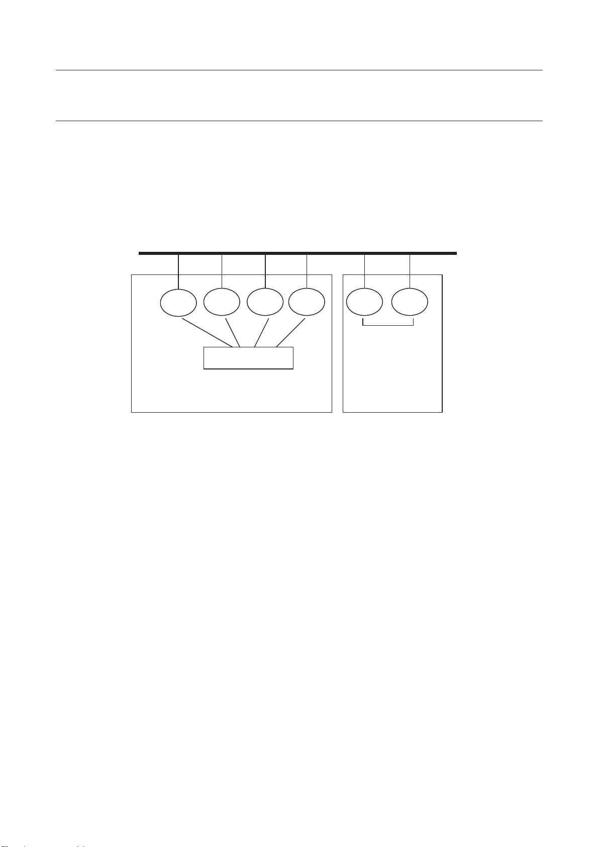
z Configure the Ethernet network as follows: In the configuration shown in the figure below, the
controllers connect to the building network on Port #1, and form a RIPE ring using Port #2, so that
the building network and interference check RIPE ring can be isolated from each other.
Building network
Port #1
Port #2
RIPE ring with 2
controllers can be
RIPE ring with more than 2 controllers
requires an Ethernet switch
directly connected
7
Page 26
MAROBBI8204121E REV F 3 SETTINGS
RC
Ethernet Switch
RC: Robot controller
RC
RC
RC
RC
RC
3.1.1.2 Notes
Basic notes on using the robot link approach deterrence function are listed below. Your system must
satisfy the following minimum requirements at the minimum. The customer is responsible for additional
measures if required by safety standards.
z The RIPE ring must be isolated from the main Ethernet line to prevent interaction with the building
network and unintended interaction between different RIPE rings.
Building network
Port #1
Port #2
RIPE ring with 2
controllers can be
RIPE ring with more than 2 controllers
requires an Ethernet switch
directly connected
z The Ethernet cables must be routed so that they will not be accidentally damaged
z The Ethernet cables must be routed so they will not be affected by EMF noise. Avoid routing the
ethernet cables near sources of EMF noise.
z The power cable to the switching hub must be routed to avoid accidental damage or disconnection.
z Consider the Ethernet cable routing and location where the switching hub is to be installed so that
the connector of each cable can make reliable contact with the hub. If the contact is poor,
cross-controller communication could be affected and incorrect interference detection could result.
z When an Ethernet cable is connected between the Ethernet switch and the controller and both
switch and controller are powered on, the green LED on the printed circuit board at the back of the
socket glows to indicate a successful connection. If the LED does not glow, the main board may be
faulty. Contact the FANUC Service Center.
z The Ethernet switch has LEDs to indicated the communication status. Install the switch in a location
where the status LEDs can be easily observed, to help investigate communication problems if
necessary.
z On the TCP/IP setting screen, the correct IP addresses and host names must be set correctly.
Otherwise, the wrong robot might be used for interference checking. To avoid confusion, distinct
host names and IP addresses are used for each robot on the robot link network.
z RIPE communication must be configured. Otherwise, interference checking cannot be performed.
See the chapter titled "SETTINGS" in this manual for instructions to configure RIPE configuration.
z The settings on the Interference Check calibration menu must be correct and precise calibration
must be performed. Otherwise, false interference my be detected or a robot may collide because the
calibration does not match the cell configuration.
8
Page 27

3 SETTINGS MAROBBI8204121E REV F
Ether net
Switch
G1
G2
RC21
Controlle r 1
G1
RC24
Controlle r 4
G1
RC22
Controlle r 2
G1
G2
RC23
G3
Controlle r 3
CAUTION:
character string contains a space (blank) (leading spaces are difficult to check
in particular), communication cannot be performed properly. In this case, delete
the entire line, and then reenter a character string.
3.1.2 Settings
The interference check function uses Ethernet to share robot positions across controllers. Settings for
using Ethernet must be made first.
This section explains how to make the settings using the following system configuration as an example:
Controller 1 is a two-group system. Its host name is RC21.
Controller 2 is a one-group system. Its host name is RC22.
Controller 3 is a three-group system. Its host name is RC23.
Controller 4 is a one-group system. Its host name is RC24.
3.1.2.1 Setting the host names, Internet (IP) addresses, and subnet
mask
Display the Host Com setup menu, then the TCP/IP menu.
On the TCP/IP setup menu, configure the following items:
z Node name of the local controller
z Subnet mask
z Port #2 IP address. If Port #1 will be used for RIPE communication, configure Port #1 IP address
instead. If the RIPE ring uses a dedicated Ethernet switch, the IP address can be a standard value
(for example, starting with 192.168.0.2) .
z Make the above settings on all robot controllers on the RIPE ring. The settings for "Node name" and
"IP address" must be unique for each controller on the RIPE ring.
Characters must be entered to set the items on this screen. If an entered
9
Page 28

MAROBBI8204121E REV F 3 SETTINGS
Example settings are shown below:
3.1.2.2 Setting full duplex mode (for each robot controller)
Set each robot controller to the full duplex mode. Set system variable
$ENETMODE[].$FULL_DUPLEX to TRUE.
3.1.2.3 Setting full duplex mode (for the Ethernet switch)
If the ethernet switch has a DIP switch for switching between full duplex and half duplex, set the switch
to the full duplex mode. Some Ethernet switches automatically select between full duplex and half
duplex.
3.1.3 Checking the Network-Related Settings
After setting the above items, check the following items to confirm that the settings are correct:
1. Check whether an Ethernet cable is connected between the Ethernet switch and each robot
controller. (or directly between controllers if there are only two)
2. ˢ if no cable is connected, connect a cable.
3. When the power to the hub and robot controllers are on, check whether the green LEDs on the
printed circuit board at the back of the Ethernet cable socket on the main board in each robot
controller glow.
4. ˢ if the LED does not glow, reinsert the cable, and turn the power to the hub and controller off,
then on again. If the LED still does not glow, the main board may be faulty. Contact the FANUC
Service Center.
10
Page 29

3 SETTINGS MAROBBI8204121E REV F
3.1.4 Configuring RIPE automatically
Interference Check uses RIPE (ROS Internet Packets over Ethernet) to share positions between one
controller and another. Before intelligent interference check can be used, RIPE must be configured.
RIPE uses a “Master” controller which serves to coordinate the RIPE network ring, and one or more
“Slave” controllers which share the RIPE ring.
RIPE can be configured automatically using the below procedure. RIPE configuration should be done
after the host name, Port #2 IP address, and Port #2 subnet mask are configured in the Host
Comm->TCP/IP menu.
For details of RIPE setup and operations, refer to: ROS INTERFACE PACKETS OVER ETHERNET
(RIPE) chapter in the Internet Options Setup and Operations Manual
Procedure
1. Press MENUS
2. Select SETUP
3. Select Host Comm. The master Host Comm menu will be displayed.
11
Page 30
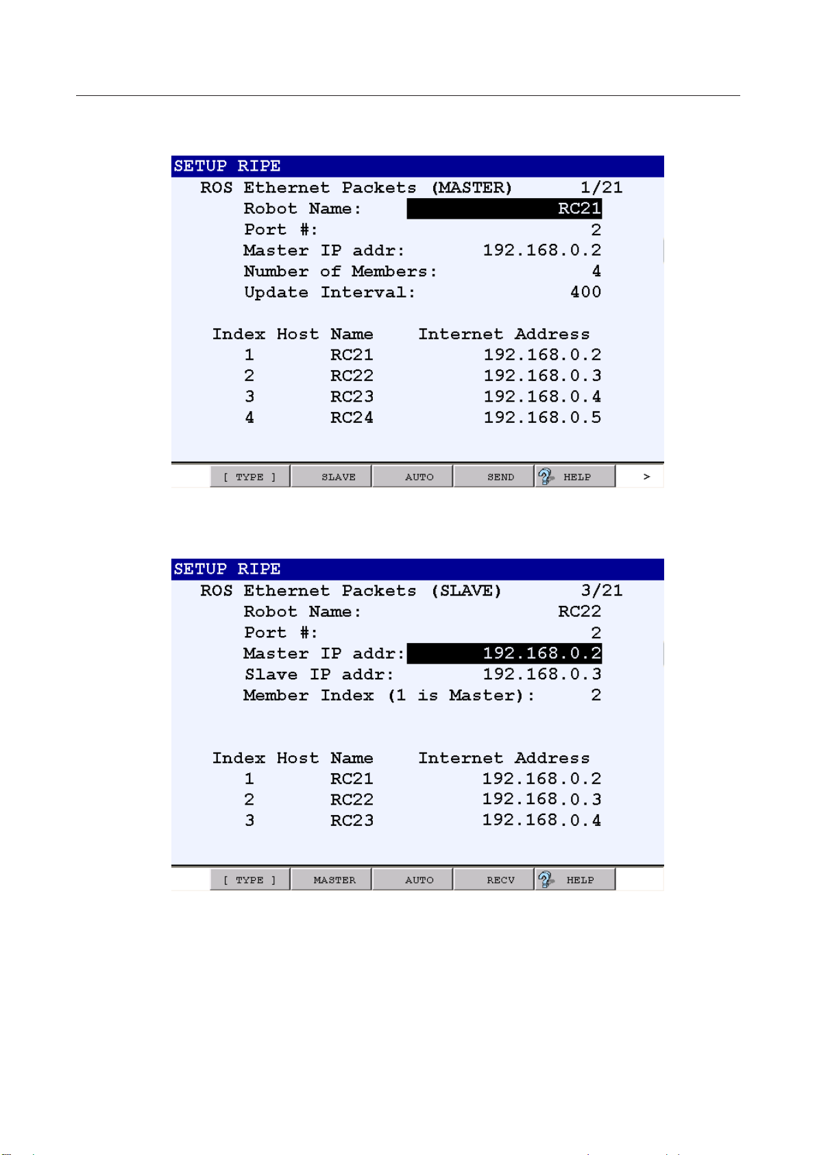
MAROBBI8204121E REV F 3 SETTINGS
4. Move the cursor to RIPE and press F3 [DETAIL] to enter the RIPE setup menu.
5. Enter a name for your robot. RC21, for example.
6. On the slave controllers, press F2 SLAVE. The following screen is displayed:
7. Set up the RIPE ring on the slave controllers
a. Select a unique “Member Index” for all slave robots 2 to n where n is the number of
controllers in the ring
b. Press F3 AUTO on all of the SLAVE controllers to configure them to WAIT for the config
file from the master
c. When “Repower after receiving data?” is displayed, select YES
12
Page 31

3 SETTINGS MAROBBI8204121E REV F
[ROSIPCFG.XML]
8. Set up the RIPE ring on the master controller. Press F2 MASTER if necessary to return to the
MASTER setup menu
a. Verify that the port number is correct. If possible, use a port that is not already in use for a
factory communications link. Typically, port #2 is available. Refer to the “Setting up a Port”
section in the Software Installation Manual for more information.
b. Set up the number of members in the ring
c. Set the Update Interval. 400ms is acceptable.
d. Press F3 AUTO on the MASTER controller to generate the ROSIPCFG.XML file and send it to
all of the waiting slaves.
e. When “Put all SLAVES in AUTO mode” is displayed, enter CONTINUE
f. When “Cycle power for setting to take effect?” is displayed, select YES to automatically cycle
power and install RIPE configuration on all controllers in RIPE ring.
3.1.5 Configuring RIPE with ROSIPCFG.XML
An alternative to automatic RIPE configuration is to directly edit ROSIPCFG.XML.
Create and install ROSIPCFG.XML according to the procedure below. ROSIPCFG.XML should be
updated whenever host name or IP address changes in the host communication menu, or a member is
added or removed from the RIPE ring.
Procedure
1. Create the following XML file (called ROSIPCFG.XML) using a text editor.
2. Make a note of the host name and IP address of all controllers connected to robot link.
3. Edit <MEMBER> tag (line 7 and 8) in ROSIPCFG.XML according to the following example.
(Example) <MEMBER name="Host name" ipadd="IP address"/>
13
Page 32

MAROBBI8204121E REV F 3 SETTINGS
<?xml version="1.0" ?>
<!--
The order implies the "index" in the ring
-->
<ROSIPCFG>
<ROBOTRING count="4" timeslot="400">
<MEMBER name="RC21" ipadd="192.168.0.2">
</MEMBER>
<MEMBER name="RC22" ipadd="192.168.0.3">
</MEMBER>
<MEMBER name="RC23" ipadd="192.168.0.4">
</MEMBER>
<MEMBER name="RC24" ipadd="192.168.0.5">
</MEMBER>
</ROBOTRING>
</ROSIPCFG>
[SETXML.CM]
frcopy mc:rosipcfg.xml frs:rosipcfg.xml
x Change count="4" (line 6) to match the number of robots, and add or remove
<MEMBER ...> lines if necessary.
4. Create the following command file (called SETXML.CM) using a text editor.
5. Copy ROSIPCFG.XML and SETXML.CM into memory card.
6. On each controller in the RIPE ring, load the ROSIPCFG.XML file using these steps:
x Display all files in the memory card using DIR *.* in the file menu.
x Select “SETXML.CM” and press ENTER key.
x Question “Execute SETXML.CM?” will appear, answer F4 (YES).
x After “OK” is appears on lower right corner of the menu, cycle power.
3.2 CALIBRATION
Calibration is to teach a robot the position of the calibration robot coordinate system viewed from the
reference robot coordinate system. More precisely, calibration is to set the position and posture of the
world coordinate system of a certain calibration robot viewed from the world coordinate system of the
reference robot.
Calibration must be performed as many times as the number of robots because all robots are required to
know their position in the reference robot coordinate system.
14
Page 33

3 SETTINGS MAROBBI8204121E REV F
CAUTION:
It is highly recommended that you use the same software version among all Ethernet
connected controllers using BIC/IIC.
If multiple controllers are used and connected through ethernet then all controllers on the robot ring must
be powered on during the calibration. RIPE and the associated rosipcfg.xml files must be set up before
calibration is started. Please refer to section 3.1 for the network setup. If only a single controller is used
then RIPE setup is not required.
This section explains calibration data, then calibration. The following outlines calibration:
z Set a calibration TCP on each robot.
z Make the TCPs of the reference robot and a robot to be calibrated touch and teach the position on
each robot.
The TCPs must touch at three different points for each pair of the reference robot and another robot.
The three points must be widely separated and form a triangle. They must not be close to a straight
line. The points are recorded separately for each robot, so there are two method of teaching the
reference points and the calibration points:
o The points can be where the robot TCPs are touching each other
o The points can be where the robot TCPs are touching the same points in space, such as a mark
or target on a fixture. It is essential that the order of the points be the same for each robot.
Example of robots touching the same points on a fixture
Example of robots touching TCPs
15
Page 34

MAROBBI8204121E REV F 3 SETTINGS
Z
Z
axis
X
axis
X
axis
R1
R2
Y
axis
Y
axis
Reference robot
R1
R2
3.2.1 Calibration Data
To use the interference check function, the positional relationships among installed robots must be set.
Calibration must be performed as many times as the number of robots because all robots are required to
know their position in the reference coordinate system.
As specific setting data, set the position (X, Y, Z) of the origin and posture (W, P, R) of the calibration
coordinate system viewed from the world coordinate system of the reference robot.
Directly enter the values of the position and posture of the calibration coordinate system to set data.
Sample calibration data
Assume that two robots are installed as shown in the figure. The zero points of these robots are deviated
from each other by 3000 mm horizontally (X-axis direction). There is no deviation vertically (Z-axis
direction) or perpendicularly (Y-axis direction). The following shows calibration data when R1 is set as
the reference robot in this status:
Data to be set for R2 when R1 is set as the reference robot
(X, Y, Z, W, P, R) = (3000, 0, 0, 0, 0, 180)
Data set automatically for R1 when R1 is set as the reference robot
(X, Y, Z, W, P, R) = (0, 0, 0, 0, 0, 0)
-axis
1
-
2
-
1
-
1
-
2
Data to be set for R2 when R1 is set as the reference robot
(X, Y, Z, W, P, R) = (0, -1500, 0, 0, 0, 0)
Data set automatically for R1 when R1 is set as the reference robot
(X, Y, Z, W, P, R) = (0, 0, 0, 0, 0, 0)
X1 Axis
Y1 Axis
Y2 Axis
Calibration robot
X2 Axis
-
2
Reference robot
Calibration robot
16
Page 35

3 SETTINGS MAROBBI8204121E REV F
3.2.2 Setting Calibration Data
Set the position and posture between two robots.
To set calibration data, directly enter the numeric values indicating the position and posture of the world
coordinate system of a calibration robot viewed from a reference robot.
Calibration data is automatically set to (0,0,0,0,0,0) for the reference robot.
Procedure
1. Press the MENUS key to display the screen menu and select "SETUP".
2. Press the [TYPE] (F1) key and select "Interference".
Menu for Intelligent Interference Check
Menu for Basic Interference Check
17
Page 36

MAROBBI8204121E REV F 3 SETTINGS
3. Position the cursor on "1 Calibration between robot <*DETAIL*>" and press the Enter key.
4. Position the cursor on the name of the robot for which calibration data is to be entered and for the
Manager Robot. (In this example, the cursor is positioned on Manager Host Name.
5. Press the [CHOICE] key. The screen changes as shown below:
18
Page 37

3 SETTINGS MAROBBI8204121E REV F
For the Manager Host Name the first name on the list should be chosen. Also use this host name for
the first Member robot. The robots are members of the ring of robots that can be calibrated for
Interference Check. The first Member robot is the reference robot for all robot calibration. The
Calibration data for all other robots will be that robot position in the reference robot world frame. In
this example the reference robot is Group 1 in the controller with host name SLMAIN.
Repeat selecting the host names for all robot groups that will be calibrated. Note that the first
Member host name, on line 2, must be the same as the Manager host name. When the first
member robot host name is entered the DONE field becomes TRUE because this robot is the
reference robot and does not need calibration data.
6. Cursor to the Group for the first Member robot and enter the group number for the reference robot.
In the example below Group 1 of the controller SLMAIN is the reference robot.
19
Page 38

MAROBBI8204121E REV F 3 SETTINGS
3.2.2.1 Direct input method
1. Set the group numbers associated with the other Members. Select the group number for the robot you
want to calibrate and press F3 (CALIB).
2. The following screen similar to the following will appear. Press F4 (CHANGE) to bring the screen
for direct entry of calibration parameters.
20
Page 39

3 SETTINGS MAROBBI8204121E REV F
3. After Press F4 (CHANGE) to allow direct entry of the calibration parameters. The screen changes to
one similar to that shown below:
4. Cursor to the value associated with each element, x, y, z, w, p, r and enter the appropriate value.
This is the location of the calibration robot world frame as seen from the reference robot world frame.
When finished, press F4 (DONE). A screen similar to the following should appear:
21
Page 40

MAROBBI8204121E REV F 3 SETTINGS
5. Note that the “Done” field has change to TRUE indicating that the robot has been successfully
calibrated to the reference robot. You can repeat for the remaining robots that need to be
calibrated:
3.2.2.2 Three point method
[Determining reference positions]
Reference positions are used for determining the positional relationships between two installed robots
(reference robot and a robot to be calibrated). If a reference position is near an operating area limit or
specific point, reference positions are close, or three reference positions are in line, the precision of
calibration becomes lower. As a guide for determining reference positions, select the vertexes of a
triangle whose sides are about 1 m long so that both robots will not assume an unnatural posture at each
position as much as possible.
Conceptual drawing of teaching a reference position
22
Page 41

3 SETTINGS MAROBBI8204121E REV F
Procedure
Follow the procedure described above to set up the reference and calibration robots host names and
group numbers. The screen should look similar to the following:
1. Follow the procedure for the “Direct Entry” method described above until you get to the screen after
pressing the “CALIB” softkey. The screen should look similar to the following:
23
Page 42
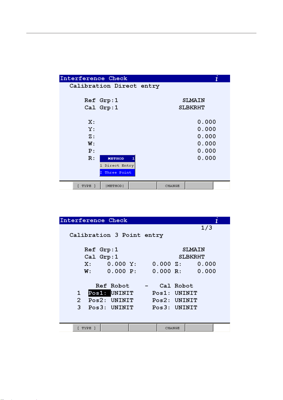
MAROBBI8204121E REV F 3 SETTINGS
2. The following screen similar to the following will appear. Press F2 ([METHOD]) to bring the popup
window that allows for selection of the Three Point methods, similar to the following:
3. Select “2 Three Point” from the popup menu to bring up a screen similar to the following:
24
Page 43

3 SETTINGS MAROBBI8204121E REV F
4. Press F4 (CHANGE) to record or edit the position data. The screen will remain the same but the
softkey mapping will change to the following:
For each robot you must teach three positions, Pos1, Pos2, and Pos3. The positions must correspond to
each other. For instance Pos1 on the Reference robot and Pos1 on the Calibration robot must be the
same point. Similarly Pos2 and Pos3 on the Reference robot must be touching the same point as Pos2
and Pos3 on the Calibration robot.
You do not have to teach the points at the same time. For instance, if you want to touch the same point
on a fixture with each robot you can touch first with the Reference robot and teach one or more points
then, when the Reference robot is out of the way you could teach the same points with the Calibration
robot. You can touchup the points at any time.
If you inadvertently record the wrong position you can select F3 CLEAR to make the position UNINIT
so it is obvious which points need to be recorded.
You must record the points on the controller for that robot. For instance if the Reference robot is on
SLMAIN controller and the Calibration robot is on the SLBKRHT controller then you must record the
points for the Reference robot on the SLMAIN controller teach pendant and the points for the Calibration
robot on the SLBKRHT controller. The points are automatically updated on both controllers when they
are recorded.
5. After all positions have been recorded for both robots the screen should look like the following:
25
Page 44

MAROBBI8204121E REV F 3 SETTINGS
CAUTION
is not complete unless the [COMPLETE] key is
pressed.
When you are finished you must press F2, COMPLETE, to calculate the calibration parameters. If
calibration is successful the menu will return to the Calibration Setup menu. If the calibration is not
successful then an error message will be displayed and some of the calibration positions will
become UNINIT.
Registration of calibration data
6. Note that the “Done” field has changed to TRUE indicating that the robot has been successfully
calibrated to the reference robot. You can repeat for the remaining robots that need to be
calibrated:
----Screen after setting----
26
Page 45
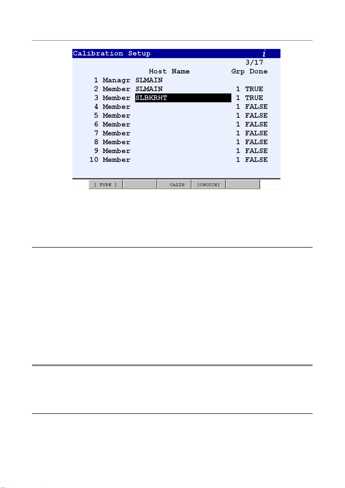
3 SETTINGS MAROBBI8204121E REV F
3.2.3 Troubleshooting
1. “Position not recorded” is displayed when trying to record a position.
Check the following item:
z Check that you are recording with the teach pendant for the robot being recorded. You must
use the teach pendant of the reference robot to record the reference robot positions. You must
use the teach pendant of the calibration robot to record the calibration robot positions.
2. “Points too close” is displayed when trying to COMPLETE a calibration
Check the following item:
z Check that the distances between points are at least 200mm and form a triangle and are not
close to a straight line.
3.3 SETTING MODELS
This section covers the following topics:
z Model and element definitions
z How to set hand, fixture, and robot models
3.3.1 Definition of Elements
Each model consists of several elements. This subsection explains elements in more detail.
Each element has the following parameters:
z Enabled/Disabled
27
Page 46

MAROBBI8204121E REV F 3 SETTINGS
CAUTION
Set the model as least 24 mm larger than the physical entity. This margin is to
speed.
z Link Number (Link No.)
z Link type
z Shape
z Size
z Pos1
z Pos2
These parameters are explained in detail in the following.
Enabled/Disabled
When this parameter is set to "ENABLED", the element is active. The default value is "DISABLED"
(except for the parameters that are factory-set for a robot.)
Link Number (Link No.)
Each element is attached to the coordinate system of a link. The link number indicates the number of the
robot link that the current element is attached to. For a hand element, this item is 99 that indicate the
element is attached to the coordinate system of the end-effector faceplate. The world coordinate system
is used as the reference coordinate system of a fixture regardless of the number set.
Link type
This parameter indicates how the link is attached. It is mainly used for setting an element of a robot.
The default value is "NORMAL".
Shape
This parameter indicates the geometric shape of an element. Currently, "Sphere" and "Cylinder" are
supported for the hand model and robot model. For fixture models, additional “Plane_inf”, “plane_fin”
and “Box” shape are also supported.
Size
This parameter is used for determining radius of a sphere and cylinder. This parameter is not used for
other type of shapes.
ensure the robot has adequate time to decelerate for various programming
Pos1, Pos2, Pos3 and Pos4
When an element is a “Sphere” type, it uses “Pos1” as its center with respect to its specific coordinate
system. The “Pos2 “, “Pos3”, “Pos4” are not used for the Sphere type.
When an element is a “Cylinder” type, it uses both “Pos1” and “Pos2” to define the centers of the two
sphere at the ends of the cylinder. The ordering of the “Pos1” and “Pos2” is not important. “Pos3” and
“Pos4” are not used for the Cylinder.
When an element is defined as either “Plane_inf” or “Plane_fin” type, “Pos1” is the origin of the plane,
and “Pos2” defines the X direction of the plane and “Pos3” defines the Y direction of the plane. “Pos4”
is not used.
When an element is defined as “Box” type, “Pos1” is the origin of the box, “Pos2” defines the size and
direction of the X axis, “Pos3” defines the size and Y axis, and “Pos4” defines size and the Z axis.
28
Page 47
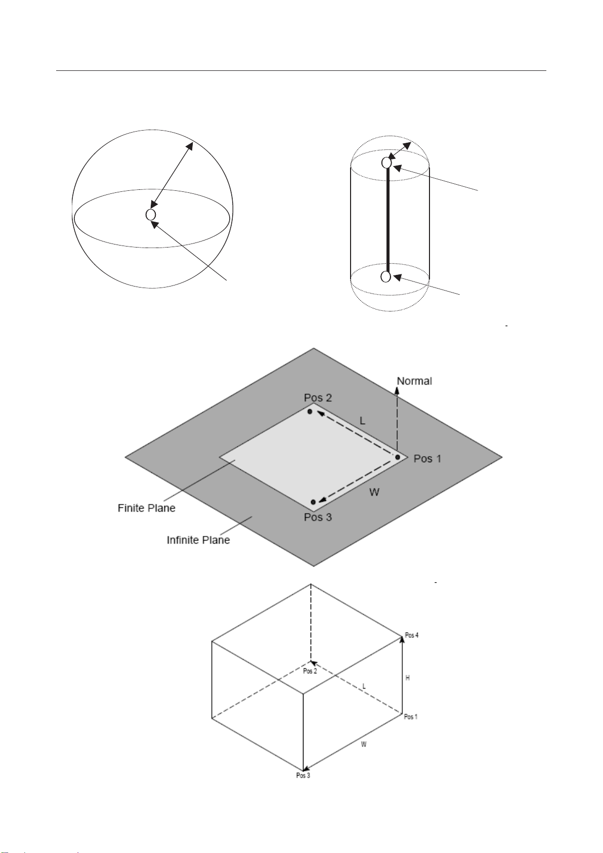
3 SETTINGS MAROBBI8204121E REV F
Sphere
Pos1
Size
Cylinder
Pos1
Pos2
Size
Conceptual drawings of elements
29
Page 48

MAROBBI8204121E REV F 3 SETTINGS
How to Teach a Plane Element Effectively
In order to create a plane element, you need to teach three points to define the plane. The method
you use to teach the three points (Pos 1, Pos 2 and Pos 3) determines which side of the plane is
outside the plane element.
If you think of the plane element as a wall (virtual wall) separating the inside and the outside of a
room, one side of the plane is outside the plane element, and the other side is inside the plane
element. The outside of a plane element is a zone where access is unrestricted, and the inside of
the plane element is a zone where access is restricted.
By convention, the outside of a plane element is determined by the direction of the normal to the
plane, which is determined by the three points: Pos 1, Pos 2 and Pos 3. You can teach the three
points that define the desired plane by following the right hand rule.
Right Hand Rule
To determine the direction of the normal to the plane defined by Pos 1, Pos 2, and Pos 3 do the following.
• Point your index finger along the direction from Pos 1 to Pos 2.
• Point your middle finger along the direction from Pos 1 to Pos3.
• Hold your thumb perpendicular to the plane formed by both your index finger and middle finger.
• Your thumb will then point in the direction of the normal to the plane defined by Pos 1, Pos 2 and Pos 3.
Right Hand Rule Example
Infinite Plane and Finite Plane
By definition, the infinite plane and finite plane differ by the fact that the finite plane has dimensions
of the finite plane (width W and length L) are determined from the location of the three taught points:
Pos 1, Pos 2 and Pos 3.
Plane Example
The following figure shows two similar plane elements with different sides as the outside of the plane
(opposite orientation). If plane 1 and plane 2 in this example are infinite planes (with infinite dimensions)
they are the same plane, with opposite orientation.
30
Page 49

3 SETTINGS MAROBBI8204121E REV F
Plane 1 and plane 2 have opposite orientation because of the way Pos 1, Pos 2 and Pos 3 are arranged
in the two cases. By the right hand rule, you can verify that the arrangements of the three taught points:
Pos 1, Pos 2 and Pos 3 for plane 1 and plane 2 define two similar planes with opposite orientation.
How to Teach a Box Element Effectively
In order to teach a box element, you need to teach three points (Pos 1, Pos 2, and Pos 3) to define a
rectangular plane, and then teach Pos 4 to define the height of the box. If Pos 4 is taught inside of
the plane, an error message “Four points not form a box” will be posted on the teach pendant.
Length (L) and width (W) are calculated by the rectangular plane formed by Pos 1, Pos 2, and Pos
3. Height (H) is defined by Pos 4 and the plane.
31
Page 50

MAROBBI8204121E REV F 3 SETTINGS
CAUTION
The more geometric elements enabled in the interference check, the longer the
required processing time.
Each Hand model can have up to five geometric elements, while each fixture model can have up to two
geometric elements. A robot can have up to 10 geometric elements. To reduce the computation time, the
least number of graphical elements possible should be used.
Examples of model elements assigned to a robot and a fixture
3.3.2 Setting Up a Hand Model
This subsection explains how to set up a hand model. To set a hand model up, the following steps should
be taken:
z Enter a Comment
The comment can be used for assigning a name to each model. This field is optional. When set it
can be used to conveniently distinguish between different elements.
z Create a model
Create a model as described in Subsection 3.1.1, "Definition of Elements." Each hand may have up
to five geometric elements defined. If too many geometric elements are defined in a cell, an
SSPC-185 error will be posed. Please refer to CHAPTER 2, "OUTLINE." To resolve this issue.
When "Link No." is set to 99, the position of each element is with respect to the faceplate
coordinate system..
You may want to enable the relative view to see the graphic display of the model you are
constructing. Place the robot at its zero position for a better view of the relationship between the
tool and the robot.
32
Page 51

3 SETTINGS MAROBBI8204121E REV F
Z
Y Z X
Sizes
Element 1
Element 2
Element 3
Settings for each element
Item/element
Element 1
Element 2
Element 3
Enabled/Disabled
ENABLED
ENABLED
ENABLED
Link No.
99
99
99
Link type
NORMAL
NORMAL
NORMAL
Shape
Cylinder
Sphere
Cylinder
Size
40.0
100.0
30.0
Pos1 X
-40.0
151.0
151.0
Y
0.0
0.0
0.0
Z
25.0
29.0
164.0
z Associate a hand number to a tool frame
The hand model is not used if it is not associated with a user tool and the user tool has to be active
for that robot. To map a hand model to a tool, you have to go into the UT-Hand definition menu to
define the relationship between the user tool number and the hand model number. Section 3.1.2.5
has detail description for this menu.
You can also clear all settings for a hand model or those for each element at a time.
3.3.2.1 Hand Modeling Example
This section uses an example to illustrate the hand model setup process. Starting with a giving CAD
drawing data of a hand model and finishing with assigning the geometric model to a user tool number so
the robot can use the hand model for interference checking.
Assuming the hand is mounted on the robot’s faceplate and the robot is in its zero position. Using the
drawing of the hand, we can determine the type, size, and position of each geometric element that covers
each section in the hand. The left side of the following diagram is the CAD drawing of a welding torch,
the right side of the diagram is its associated geometric model.
Hand drawings and element drawings
Elements 1 to 3 are set as follows.
33
Page 52

MAROBBI8204121E REV F 3 SETTINGS
Pos2 X
70.0 - 87.5
Y
0.0 - 0.0
Z
25.0
-
272.0
3.3.2.2 Add Comment To A Hand Model
Procedure
1. Press the MENUS key to display the screen menu and select "SETUP".
2. Press the [TYPE] (F1) key and select "Interference”. The Interference Check main menu appears.
Note: This example uses IIC (Intelligence Interference Check) option. The BIC (Basic Interference
Check) menu has first three items in the main menu.
3. Position the cursor on "2 Models setup <*DETAIL*>" and press the Enter key. The model list
screen appears.
34
Page 53

3 SETTINGS MAROBBI8204121E REV F
COPY
3. Position the cursor on "1 Tool models setup <*DETAIL*>" and press the Enter key. The Hand
figure list screen appears.
4. Press the Enter key. The comment edit screen appears. Press the F1 to F5 keys and enter a comment
statement. Up to 13 characters can be entered.
3.3.2.3 Edit Geometric Elements For A Hand Model
Procedure for setting a model
1. Display the Hand figure list screen, referencing Subsection 3.1.2.2, "Add comment To A Hand
Model."
35
Page 54

MAROBBI8204121E REV F 3 SETTINGS
COPY
2. Position the cursor at a hand of interest and press [DETAIL] (F2) key. The element list screen
appears.
3. You can use this screen to specify whether to enable or disable an element, change its shape, and set
its size.
z To enable or disable an element
Position the cursor on "ENABLED" or "DISABLED" for a desired element and press the
[ENABLED] (F4) or [DISABLED] (F5) key.
z Setting the size
Position the cursor on the field under "Size" for a desired element and directly enter size data
z Changing the shape
Position the cursor on the field under "Shape" for a desired element and press the [CHOICE]
(F4) key. The screen for selecting "Sphere" or "Cylinder" appears. On this screen, you can set a
desired shape.
36
Page 55

3 SETTINGS MAROBBI8204121E REV F
z Displaying detail data for each element. For more detail information of a particular geometric
element of this hand, position the cursor at the element and press the F2 key, to get to the detail
screen. See next section for detail.
3.3.2.4 Setting Detail Data For A Hand Geometric Element
This menu is used to set detail information of a geometric element of a hand. The detail explanation of
the field of the geometric element, please refer to Section 3.1.1.
The geometric element’s detail screen is shown as follows:
z To enable or disable this geometric element:
Position the cursor on "ENABLED" or "DISABLED" and press the [ENABLED] (F4) or
[DISABLED] (F5) key.
z To Change the element’s "Link No." and "Link type":
For hands, set "Link No." to 99 and "Link type" to "NORMAL" and do not change the
settings. (Except when a hand is NOT mounted on a robot’s faceplate)
z To Change the element’s shape:
Position the cursor on data set for "Shape" and press the [CHOICE] (F4) key. The screen for
selecting "Sphere" or "Cylinder" appears. On this screen, you can set a desired shape.
z To change the element’s size:
Position the cursor on the field indicating the size and enter a number for the size of the element.
z To change element’s positions:
For both "Pos1" and "Pos2", position the cursor on the field for a coordinate axis and directly enter
data. When the shape of the element is set to "Sphere", set the coordinates of the center for "Pos1".
For "Sphere", "Pos2" data is ignored. When the shape is "Cylinder", "Pos1" and "Pos2" may be
specified in no particular order. The faceplate frame is used as the reference coordinate system. Use
drawing data and enter values, referencing Subsection 3.1.2.1, "Sample hand modeling."
37
Page 56

MAROBBI8204121E REV F 3 SETTINGS
CAUTION
Once an element is cleared, all data of the element is deleted.
Clearing an element
You can restore all data of an element to its initial values.
Press the [CLEAR] (F3) key on the detail element data screen. The following message appears:
"Clear this element? [Y=1/N=else]:"
To clear the element, enter 1.
3.3.2.5 Mapping A Hand With A Tool Number
The interference checking function uses a table to map the hand model to a tool number. A hand is not
used unless it has been map to a tool used by the robot. For a particular robot, if its hand number is 0,
IIC/BIC assumes there is no geometric model associated with the robot’s tool.
Setting a hand correspondence table
1. Display the Hand figure list screen.
38
Page 57

3 SETTINGS MAROBBI8204121E REV F
COPY
2. Select the [UT_DATA] (F4) key. The UT-Hand definition screen appears. (This screen is displayed
regardless of where the cursor is positioned on the Hand figure list screen.)
3. Check the value set for "GROUP" and enter the number of a desired hand for the corresponding tool
number. In the above example, hand number 1 is mapped to tool number 4 in group 1. Therefore,
when the group 1 is using UTool number 4, IIC/BIC will use hand 1’s geometric information in its
calculation.
4. Press the [GROUP] (F2) key and make the select another robot group. You can select the same hand
model for different groups (when they share the same tool). You can also assign another Utool
number to the same hand. .
39
Page 58

MAROBBI8204121E REV F 3 SETTINGS
CAUTION
deleted.
z
COPY
3.3.2.6 Clear A Hand Model
You can clear the settings of a hand model. The comment statement and all element settings are reset.
Once a model is cleared, its comment and element data are all permanently
Procedure for Clearing a hand model
1. Display the Hand figure list screen.
2. Position the cursor on a hand to be cleared and press the [CLEAR] (F3) key. The following
confirmation message appears:
3. To clear the hand, enter 1.
3.3.3 Setting Up A Fixture Model
This subsection describes the three steps in setting up a fixture model:
z Enter Comment
Add comment to describe a fixture. This step is not required, but it makes the fixture much more
clear and distinguishable between many fixtures.
z Select Reference Robot
Specify the group whose world frame is used as the reference coordinate for the fixture.
Create Geometric Model For The Fixture
Set a model as described in Subsection 3.1.1, "Definition of Elements."
Each fixture may have up to two geometric elements. If many elements are created it may trigger an
alarm. Please see CHAPTER 2, "OUTLINE” for detail.
You can directly enter the position data or teach a position using the reference robot to specify the
position of an element.
The "Link No." and "Link type" are ignored. The position of each element is in the world
coordinate frame of the specified group.
You can also clear all settings for a fixture model or those for each element at a time.
40
Page 59
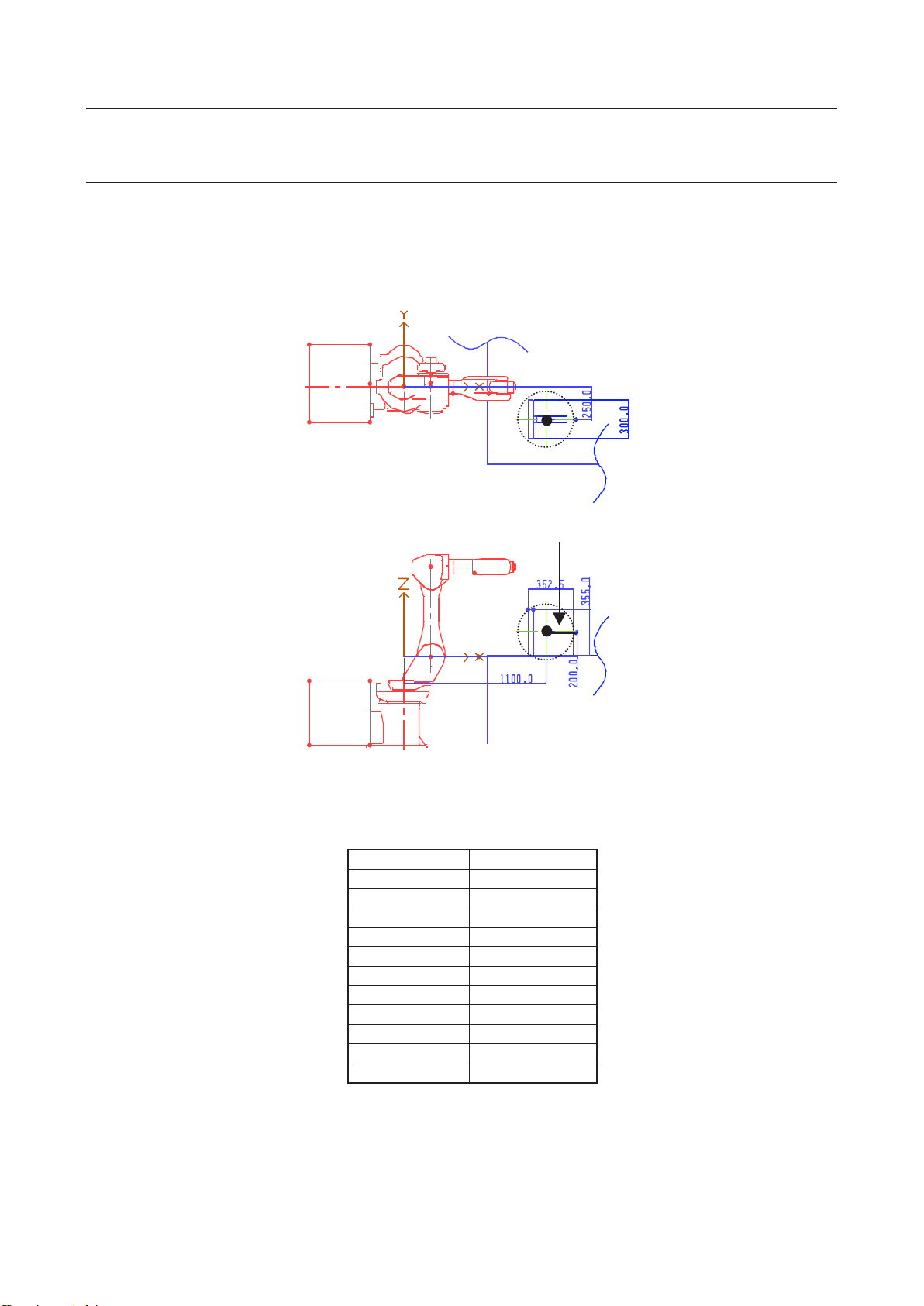
3 SETTINGS MAROBBI8204121E REV F
Size
Settings for the element
Item/element
Element 1
Enabled/Disabled
ENABLED
Link No.
0
Link type
NORMAL
Shape
Sphere
Size
230
Pos1 X
1100.0
Y
-250.0
Z
200.0
Pos2 X
――
Y
――
Z
――
3.3.3.1 Fixture Model Example
This section uses an example to show how to setup a geometric model for a fixture.. Assume that a robot
(FANUC robot M-6i in this case) and a fixture are installed as shown. The world frame of the robot is
used as the reference frame of the position of elements (for the M-6i, the origin of the world frame is
located at the intersection of the extension line of the rotation axis of the J1-axis and the line horizontally
drawn from the center of the rotation of the J2-axis as shown in the figure).
The settings for the element are as follows. (Note: No value is set for "Pos2" since sphere is used to
model the fixture.)
In the above figure, the position relative to the robot (in the world coordinate system) has been known.
You can also teach the position using the M-6i robot. (See Subsection 3.1.3.5, "Setting a fixture model
(details of an element)").
41
Page 60

MAROBBI8204121E REV F 3 SETTINGS
3.3.3.2 Enter A Comment
Procedure
1. Press the MENUS key to display the screen menu and select "SETUP".
3. Press the [TYPE] (F1) key and select "Interference". The setting list screen for the Interference
Check appears.
4. Position the cursor on "2 Models setup <*DETAIL*>" and press the Enter key. The model list
screen appears.
5. Position the cursor on "2 Fixture models setup" and press the Enter key. The Fixture figure list
appears::
42
Page 61
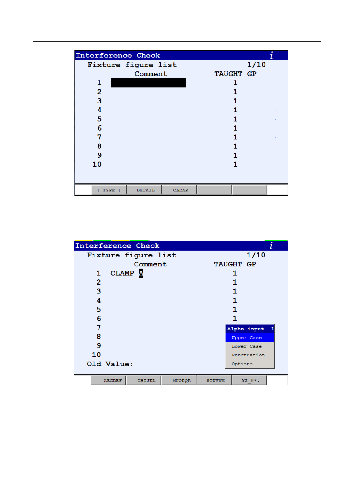
3 SETTINGS MAROBBI8204121E REV F
COPY
6. Press the Enter key. The comment edit screen appears. Press the F1 to F5 keys and enter a comment.
The comment can be up to 13 characters.
43
Page 62
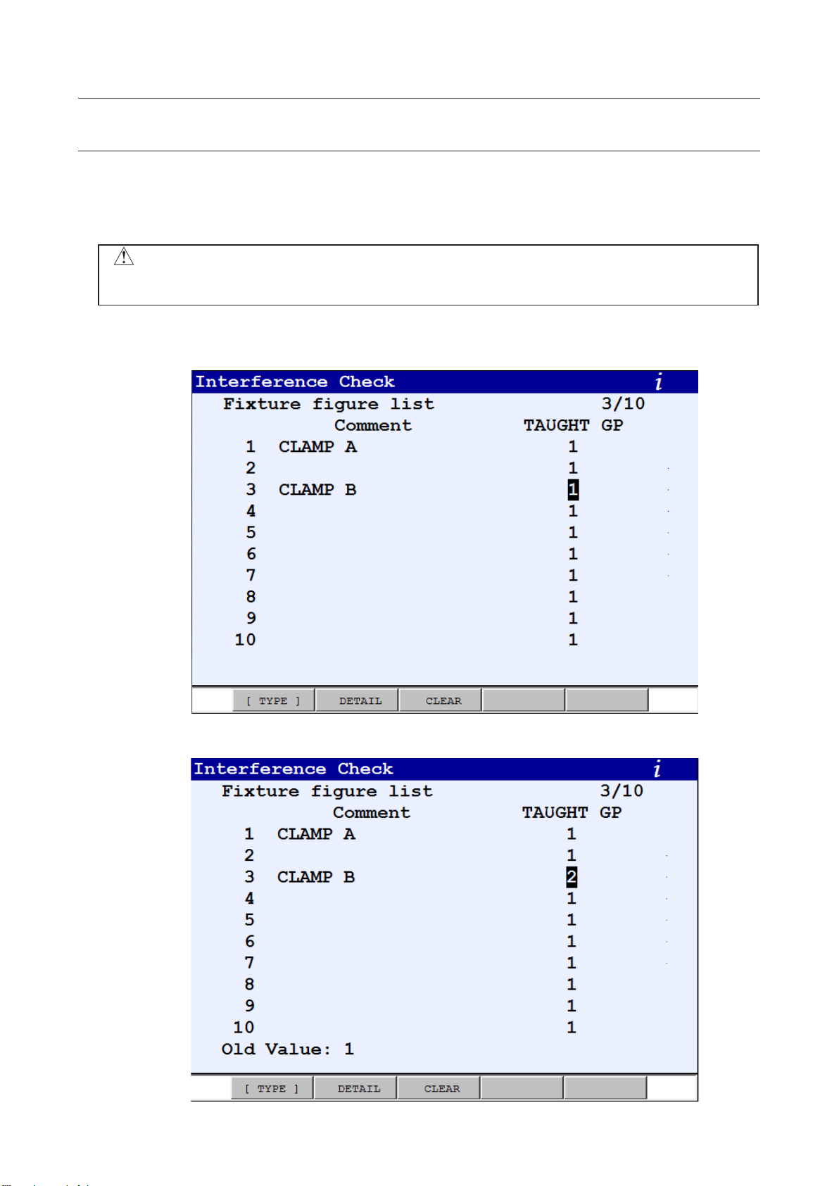
MAROBBI8204121E REV F 3 SETTINGS
CAUTION
The geometric information of a fixture is invalid without a taught group. Before
setting a fixture’s geometric property, always select its taught group first.
COPY
COPY
3.3.3.3 Select Reference Robot Group
The position of a fixture has to refer to the world frame of a robot, so interference check can establish the
spatial relationship between the fixture and all robots. Since all robots are calibrated within the cell, even
if a fixture uses robot 1 as its reference, Interference Check still can check possible collision between the
fixture and robot 2, for example.
Procedure
1. Display the Fixture figure list screen, referencing Subsection 3.1.3.2, "Enter A Comment”
2. Position the cursor on the field under "TAUGHT GP" for a target fixture and directly enter a value.
44
Page 63
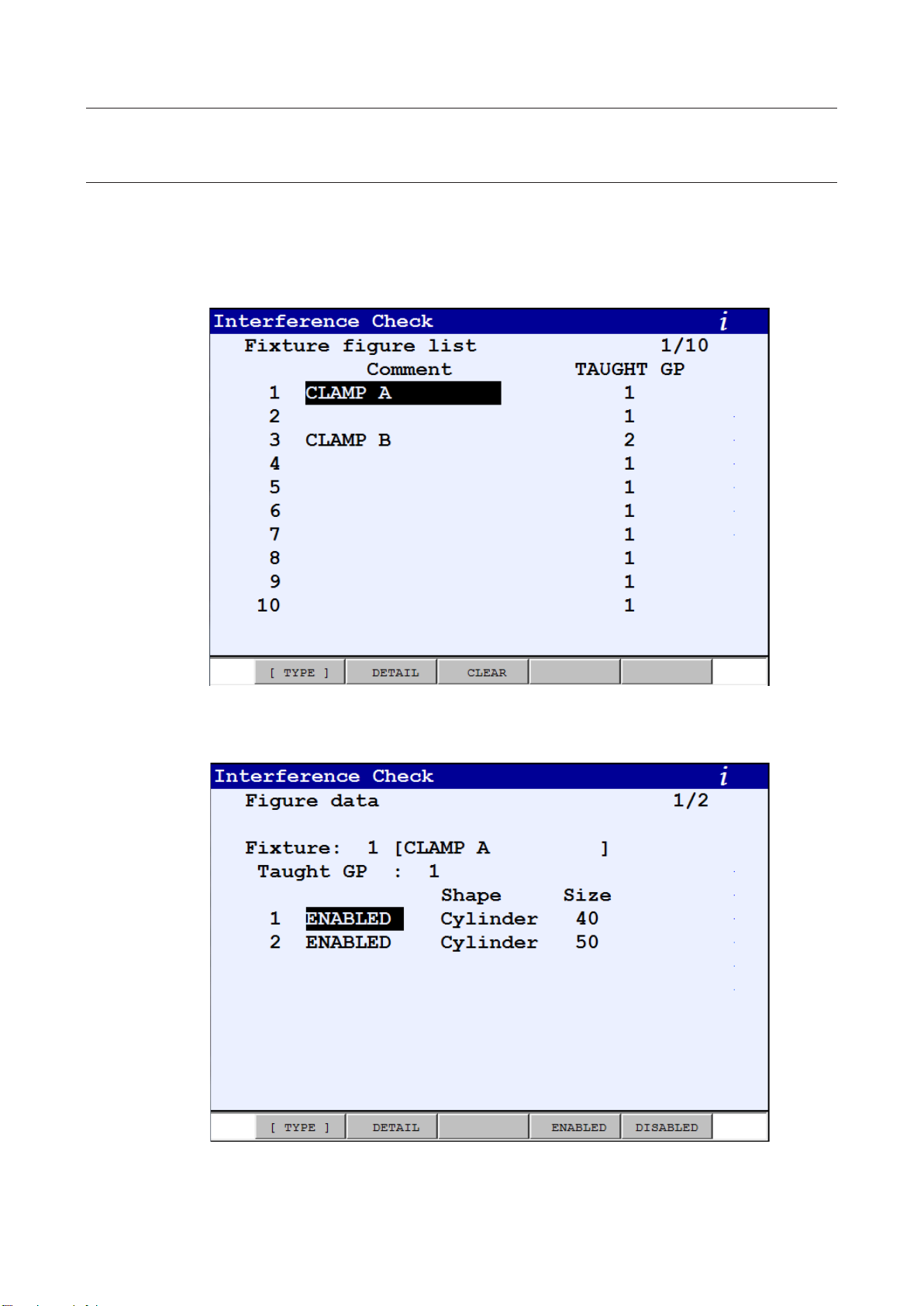
3 SETTINGS MAROBBI8204121E REV F
COPY
3.3.3.4 Create Geometric Model
Each fixture model can have up to two geometric elements. You can create a fixture by following the
procedure outlined below.
Procedure for setting a model
1. Display the Fixture figure list screen.
2. Position the cursor on a fixture that you want to check or modified and press the [DETAIL] (F2)
key. The Figure data list screen appears.
45
Page 64

MAROBBI8204121E REV F 3 SETTINGS
3. You can use this screen to specify whether to enable or disable each element, change its shape or
size. You can also go to detail data screen for each element by pressing the F2 key.
z Specifying whether to enable or disable an element
Position the cursor on "ENABLED" or "DISABLED" for a desired element and press the
[ENABLED] (F4) or [DISABLED] (F5) key.
z Changing the shape
Position the cursor on the field under "Shape" for a desired element and press the [CHOICE]
(F4) key. The screen for shape selection appears. On this screen, you can set a desired shape.
z Setting the size: Position the cursor on the field under "Size" for a desired element and directly enter
size
z Displaying detail data for each element
On the Figure data screen, press the F2 key. The detail screen for the element on which the
cursor is positioned appears. For how to set detail data, see Subsection 3.1.3.5, "Setting a
fixture model (details of an element)."
46
Page 65

3 SETTINGS MAROBBI8204121E REV F
Size
Recorded as "Pos1"
Recorded as "Pos2"
3.3.3.5 Setting Fixture Elements
For fixture elements, "Link No." and "Link type" are not used. Describe the position of an element
based on the world coordinate system of the group set for the taught group. You can also move the TCP
of a robot in the taught group to the set position by jog feed and record the position using the setting
screen to specify data for "Pos1" and "Pos2".
Conceptual drawing of teaching position data (recorded using the detail element
data screen)
For each element, see Subsection 3.1.1, "Definition of Elements."
Setting an fixture element
Press the [DETAIL] (F2) key on the Figure data list screen. The detail element data screen appears.
z Specifying whether to enable or disable the element
z Changing the shape
Position the cursor on "ENABLED" or "DISABLED" and press the [ENABLED] (F4) or
[DISABLED] (F5) key.
Position the cursor on data set for "Shape" and press the [CHOICE] (F4) key. The screen for
selecting "Sphere", “Cylinder”, “Plane_inf”, “Plane_fin” and “Box” appears. On this screen, you
can select a desired shape.
47
Page 66

MAROBBI8204121E REV F 3 SETTINGS
CAUTION
Before moving the robot, make sure the current selected group matches
the taught group.
CAUTION
Once an element is cleared, all data of the element is deleted.
z Entering the size (direct entry)
Position the cursor on the field indicating the size and directly enter size data. The size data is only
valid for Sphere and Cylinder type. It is not used for “Plane_inf”, “Plane_fin” or “Box” type.
z Teaching the position (with respect to the world frame of the taught group)
1. Position the cursor on "Pos1 on World frame: <*Record*>".
2. Turn on the Teach Pendant, select the taught group and move the robot’s tool
center point (TCP) of to the desired position.
3. Press the [RECORD] (F5) key while holding the SHIFT key down. When the position has been
recorded, the message "Position was recorded." appears and position data is updated.
4. After the position is recorded, check that the displayed position data to make sure the position
is recorded with respect to the taught group.
5. Follow the same steps to record position for “Pos2”, “Pos3” and “Pos4” if they are required.
z Directly entering position data
For "Pos1". “Pos2", “Pos3” or “Pos4”, move the cursor to the field of a position and enter the
position data directly. For Sphere, only “Pos1” is required. For Cylinder, it requires both “Pos1”
and “Pos2”. For Plane_inf or Plane_fin, it requires “Pos1”, “Pos2” and “Pos3”. Finally, for Box
type, it requires all four positions.
Clearing an element
You can clear of an element to its initial values.
Press the [CLEAR] (F3) key on the detail element data screen. The following message appears:
"Clear this element? [Y=1/N=else]:"
To clear the element, enter 1.
48
Page 67

3 SETTINGS MAROBBI8204121E REV F
CAUTION
Once a model is cleared, its comment and element data are all deleted.
COPY
3.3.3.6 Clearing a Fixture Model
You can clear the settings of a fixture model. The comment statement and all element data are reset.
Procedure for clearing a fixture model
1. Display the Fixture figure list screen.
2. Position the cursor on a fixture you want to clear and press the [CLEAR] (F3) key. The following
confirmation message appears:
To clear the fixture, enter 1.
3.3.4 Setting Up A Robot Model
This subsection explains how to view and add additional geometric elements to an existing robot model.
The geometric model of a robot is defined in the factory and it should not be altered. However, you can
view the robot’s model using the Interference Check menu. In addition, you can add geometric elements
to the existing robot model to represent physical parts that are attached to the robot arm, such as a
repeater box.
A robot model can have up to 10 geometric elements. Usually, the factory uses five elements and you can
use the rest to add geometric elements to the model. An alarm may occur if too many geometric elements
are defined in a work cell, please refer to the paragraph about the number of element settings in
CHAPTER 2, "OUTLINE."
3.3.4.1 View Robot List
You can use the following procedure view all the robot models that connected to the controller.
49
Page 68

MAROBBI8204121E REV F 3 SETTINGS
Procedure
1. Press the MENUS key to display the screen menu and select "SETUP".
2. Press the [TYPE] (F1) key and select "Interference". The setting list screen for the Intelligent
Interference Check function appears.
3. Position the cursor on "2 Models setup <*DETAIL*>" and press the Enter key. The model list
screen appears.
3. Position the cursor on "3 Robot models setup <*DETAIL*>" and press the Enter key. The Robot
figure list screen appears.
50
Page 69

3 SETTINGS MAROBBI8204121E REV F
COPY
COPY
On this screen, press the [DETAIL] (F2) key to go to the detail screen for the robot on which the cursor
is positioned.
3.3.4.2 View Geometric Elements of A Robot model
You can view all geometric element of a robot model. You can even modify geometric elements if they
are not part of factory setting.
Element list screen
1. Display the Robot figure list screen.
2. Position the cursor on a robot and press the [DETAIL] (F2) key to bring up the figure data screen:
51
Page 70

MAROBBI8204121E REV F 3 SETTINGS
3. For factory define elements, you can enable or disable these elements, but you cannot change its
shape, nor can you change its size. You can view the detail of these elements by press the
[DETAIL] (F2) key, but you cannot modify these data in the Element data menu.
4. Number of factory defined geometric elements is robot dependent.
5. For the rest of geometric elements, you can use the cursor to enable or disable them, or change their
shape or size. In addition, you can use the [DETAIL] (F2) key to go into the Element data screen to
change its locations.
z Specifying whether to enable or disable an element
Position the cursor on "ENABLED" or "DISABLED" for a desired element and press the
[ENABLED] (F4) or [DISABLED] (F5) key.
z Changing the shape
Position the cursor on the field under "Shape" for a desired element and press the [CHOICE]
(F4) key. The screen for selecting "Sphere" or "Cylinder" appears. On this screen, you can set
a desired shape.
52
Page 71

3 SETTINGS MAROBBI8204121E REV F
z Setting the size
Position the cursor on the field under "Size" for a desired element and directly enter size data.
z Displaying detail data for each element
On the Figure data screen, press the F2 key will take you to the detail Element data screen for
the selected element. See Subsection 3.1.4.3, "Detail element data list."
3.3.4.3 View/Edit Detail Geometric Element
For the robot’s geometric elements that are defined by the factory, you can view these elements in the
Element data screen, but this screen prevents you from editing any item on the menu. For the added on
elements, you can edit them in the Element data screen. For details of each element, see Subsection 3.1.1,
"Definition of Elements."
Detail element data screen
Press the [DETAIL] (F2) key on the Figure data list screen. The detail element data screen appears.
--Detail factory-set element data screen (cannot be edited)—
53
Page 72

MAROBBI8204121E REV F 3 SETTINGS
--Detail data screen for an element, which can be set—
z Enable/Disable the geometric element
Position the cursor on "ENABLED" or "DISABLED" and press the [ENABLED] (F4) or
[DISABLED] (F5) key.
z Changing data set for "Link No." and "Link type"
For robots, set "Link No." and "Link type", referencing figures in Appendix.
z Changing the shape
Position the cursor on data set for "Shape" and press the [CHOICE] (F4) key. The screen for
selecting "Sphere or "Cylinder" appears. On this screen, you can set a desired shape.
z Entering the size
Position the cursor on the field indicating the size and directly enter size data.
54
Page 73

3 SETTINGS MAROBBI8204121E REV F
z Entering position data
For both "Pos1" and "Pos2", position the cursor on the field for a coordinate axis and directly enter
data. When the shape of the element is set to "Sphere", set the coordinates of the center for "Pos1",
and the data for "Pos2" is ignored. When the shape is "Cylinder", "Pos1" and "Pos2" both needed to
be specified but they are not in particular order. The frame of the specified link number is used as
the reference frame.
3.3.5 Using 4D Graphics In Model Setup Menus
If the 4D Graphics (R764) option is installed in the controller with the IIC/BIC, you can use the 4D
graphics to set up the geometric models for the Hand, Fixture and Robot. You can check to see if the 4D
graphics is loaded or not by holding the i key and press the MENU button at the same time. This will
bring the Top Menu, check the F3 key, if the key is marked “4D”, the 4D graphics is loaded.
If the teach pendant (TP) has a touch screen, you can press the i using your finger, or just hold down the
i-key on the TP and press the Fctn key at the same time. This will bring up the relative view selection
window in the top right corner of the TP. Select the 4D Visualization and press the Enter key will bring
up the relative view for the IIC/BIC software.
If the TP has only one pane before bring up the relative view, the screen will split into two panes, the left
pane displays the IIC/BIC menu and the right pane shows the 4D graphics for the cell. If the screen
already has two panes, the right pane is then taken over by IC/BIC graphics. If the screen has three panes
before the relative view, the relative view will also be displayed in the right upper pane. For the screen
that is split horizontally before the relative view, the relative view will take the lower pane.
The relative view will display the 4D graphics based on the current IIC/BIC menu. If you are not in the
detail model setup menus for the Hand, Fixture or the Robot, the relative view will display the whole
IIC/BIC cell, which includes:
1. All robots that are defined in the IIC/BIC calibration menu with their geometric model. If any
these robots have their utool defined with hand model (see section 3.1.2.5 , the geometric model
for the hand will also be displayed with the robot.
2. Fixture models will be displayed if they are included in the check combination setup.
3. If an critical zone is defined in the combination check, the critical zone is displayed.
An example of the IIC 4D graphics is shown below from the teach pendant of the first controller in the
cell. You can view the IIC 4D graphics from the 4D graphics menu, and select the 4D IIC Visualization
from the TYPE menu. This 4D display example cell has two controllers and each controller has 2 robots..
Each robot has its tool defined as well. The two robots on the right belong to the first controller (master
controller), the two robots on the left belong to the second (slave) controller.
55
Page 74

MAROBBI8204121E REV F 3 SETTINGS
3.3.5.1 Using 4D Graphics In Hand Model Setup Menu
You can use the 4D graphics to visualize the hand model you are constructing for a robot. For our two
controllers and 4 robots example, a two panes relative view for the hand model menu is shown below:
Select the first hand model by press the DETAIL (F2) key when the cursor is at the first hand. It will
bring you to the detail menu for the first hand: Note that the hand 1 is already associated with the robot 1
in this controller, so the hand will be shown at face plate of the top right robot, which is the robot 1 of the
master controller. Note that the graphics from the slave controller stays, but the two robots on the master
controller are now have no geometric model defined for them except the two cylinders on the first robot
that represents the hand 1.
56
Page 75

3 SETTINGS MAROBBI8204121E REV F
Note: the Pos1 and Pos2 are from the geometric elements defined for the hand 1. You can see the graphic
display in more detail if you zoom into the hand 1. Switch your focus to the right pane and use the
ZOOM (F3) key and your finger (on touch screen TP) or the up key to zoom in to the hand model:
At this menu, you can enable/disable the two geometric elements of Hand 1, and the graphics display will
change according to the setting. For example, disable the geometric element 1, the display will change to:
57
Page 76

MAROBBI8204121E REV F 3 SETTINGS
Enable the element 1 and go to the detail screen of the element 1 to set other properties of the element 1:
For example, you can change the length of the cylinder from 550 mm in Z to 300mm in Z. The graphics
will give you instant visualization feedback of your change after the ENTER key is pressed:
3.3.5.2 Using 4D Graphics In Fixture Model Setup Menu
The 4D graphic can also help you to define and to fine tune a fixture's geometric model you are working
on. The following example shows how to change a post fixture that was modeled as two spheres into a
more appropriate cylinder model with a long length in Z.
58
Page 77
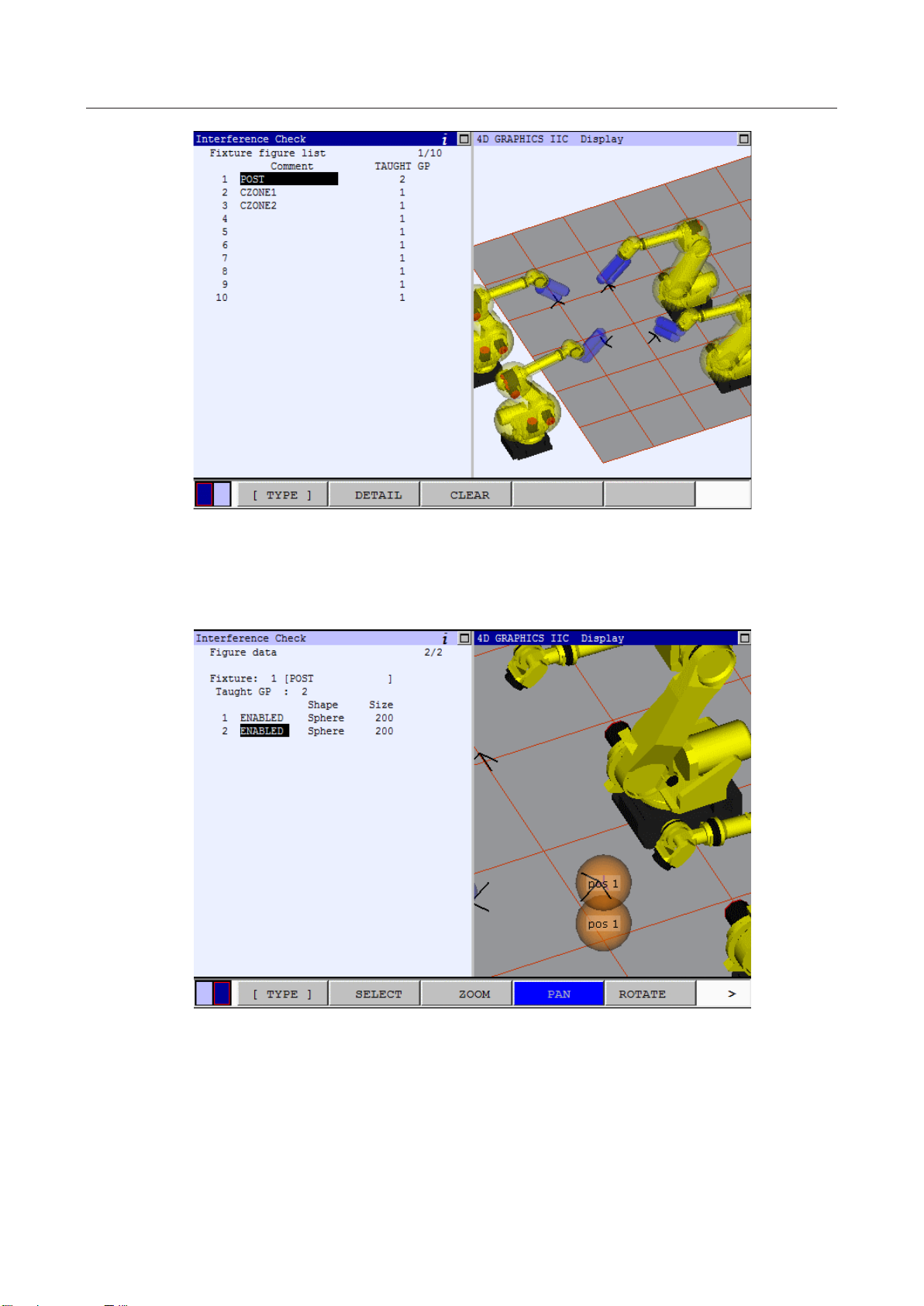
3 SETTINGS MAROBBI8204121E REV F
Press the DETAIL (F2) key to construct the geometric model of the post. The fixture is already defined
base on robot 2 of the master controller, and it is defined as two sphere as shown below. The 4D IIC
Visualization cell display does not include this fixture since it is not defined in the combination check
yet.
In this menu, disable the element 2 and change the shape of element 1 to cylinder, you will see the
graphic changed to
59
Page 78

MAROBBI8204121E REV F 3 SETTINGS
Note, since the POS2 for the cylinder was set to world frame origin of robot 2 as default, the cylinder is
now displayed from the POS1 to the world frame origin of robot 2.
In order to set the cylinder in correct location, press the DETAIL (F2) key to set up this geometric
element of the fixture model 1. Since this post is a vertical one and we like lengthen the post to 1000 mm.
Assuming that the POS 1 (X = 1000, Y = -1000, Z = -500) is at the correct position , then POS 2 should
be in X = 1000, Y = -1000, Z = 1000. Type in the correct X value for POS2, the graphics changed to the
next picture, notice that the X position has move forward by 1000 mm in the relative view:
Change Y of Pos2 to -1000, the graphics now displays:
60
Page 79

3 SETTINGS MAROBBI8204121E REV F
As you can see, the cylinder has the correct X, Y position for Pos2, change the Z on Pos2 to 500 mm will
get the desired result:
Even though the fixture 1 has its geometric model defined, it will not show up in the 4D IIC
Visualization display for the whole cell, since the fixture is not included in the combination checking.
Therefore, when leaving the fixture model setup screen, there is not fixture 1 displayed in the graphics.
To enable the checking for this fixture, go to the combination check menu and setup the fixtures:
61
Page 80

MAROBBI8204121E REV F 3 SETTINGS
Enable the Fixture 1 on line 7, and the fixture is displayed in the IIC 4D Graphic cell display:
3.3.5.3 Using 4D Graphics In Robot Model Setup Menu
The 4D graphics can help you to put a dress up on a robot. In the following example, we will add a
cylinder to link 3 of the first robot in the master controller as an example: The first robot of the master
controller is the robot at the upper right corner in the TP relative view display:
62
Page 81

3 SETTINGS MAROBBI8204121E REV F
Put the cursor at the first robot, and press the DETAIL (F2) key, the TP will show the following picture.
Note that second robot of the master controller is now without the geometric model define on it, but the
first robot does.
To add a dress up on top of the link 3, follow the procedure listed below in the robot detail element
menu:
1. enable the geometric element
2. change the link no to 3 to set the dress up in the link 3 coordinate
3. change the shape to Cylinder to model the dress up.
4. change the size to 100 based on the size of the dress up.
5. enter the positions for the two points that define the cylinder.
63
Page 82

MAROBBI8204121E REV F 3 SETTINGS
Press the PREV key to get out of the detail robot element menu and you can view the whole cell which
includes all the four robots, their tools and dress up and the fixtures.
3.3.5.4 Data Storage of The Geometric Elements
Geometric data for the IIC/BIN is all stored in system variables that have name starting with $IA_**.
When system files are saved onto a memory card or another medium, the data is all saved in
SYSVARS.SV except for hand model data. Geometric data related to hands as described in subsection
3.1.2, "Setting Up a Hand Model" is saved in system file IA_HAND.SV. To transfer hand model data
from a controller to another controller, load the system file IA_HAND.SV at control start for the second
controller.
64
Page 83

3 SETTINGS MAROBBI8204121E REV F
3.3.6 Copying Models
In this section the model copy feature is explained. This feature allows a user to copy the models from
the same or the other controllers on the IIC ring or from DCS to the IIC models. The source of the copy is
called “From Model” while the destination of the copy is called “To Model”. Also, the user can copy
to/from an XML file.
Because the number of the available model elements might be different in IIC from that of the “From
Model”, the elements are copied only until all the available elements in the selected IIC model are filled
or all the elements of the “From Model” are copied over, whichever is reached first. As a result of the
first case, there might be elements that are not copied over.
Moreover, if the “To Model” has elements that are enabled, the screen will ask for the confirmation of
the user to proceed with the copy. When the user press F4, YES, the copy will be preformed. In case the
user presses F5, NO, the copy will not be done.
In the following sections, each of the copy methods is explained in more detail.
3.3.6.1 Copy From DCS
With this feature a user can import the models created in DCS to IIC. The DCS User Models can be
imported to either the hand or robot models in IIC. The DCS Cartesian Position Check (CPC) zones are
imported to IIC fixture models. When copying the models, the user should consider the following:
o In case of CPC zones, each zone is considered a single element and not a fixture model by
itself. So several CPC zones can be copied into different elements of a fixture model to
create a single model.
o In DCS, each CPC model is represented in a User Frame. In IIC the fixture models are
represented in the World Frame of one of the groups. As a result, when a CPC model is
copied from DCS to IIC, the copy feature transforms the CPC model such that its position in
the world remains the same. The following figure displays a fixture as it is defined in DCS
and in IIC.
65
Page 84

MAROBBI8204121E REV F 3 SETTINGS
DCS
IIC
User Models
Point
Hand and Robot models
Sphere
Line_seg
Cylinder
2Spheres
Not supported
CPC Zones
Diagonal In
Fixture Models
Box
Diagonal Out
Box
Lines
Not supported
o In copying user model, the model is directly copied to the IIC model without considering the
tool frame.
The following table shows how the elements are converted during the copy from the DCS to IIC:
Procedure for copying from DCS User Models
1. Press the MENUS key to display the screen menu and select "SETUP".
2. Press the [TYPE] (F1) key and select "Interference". The setting list screen for the interference
check function appears.
66
Page 85

3 SETTINGS MAROBBI8204121E REV F
Menu for Intelligent Interference Check
3. Position the cursor on "2 Models setup <*DETAIL*>" and press the Enter key. The model
list screen appears.
4. For:
a. Copying from DCS User Models to IIC Hand models press <*DETAIL*> on "1 Hand
models setup".
b. Copying from DCS Cartesian Position Check zones to IIC Fixture models press
<*DETAIL*> on "2 Fixture models setup".
c. Copying from DCS User Models to IIC Robot models press <*DETAIL*> on "3 Robot
models setup".
5. Press F5, COPY, and select “From DCS” from the drop down menu to see the DCS copy screen.
67
Page 86

MAROBBI8204121E REV F 3 SETTINGS
DCS User Model to IIC Hand Model copy screen
68
Page 87

3 SETTINGS MAROBBI8204121E REV F
DCS CPC Zone to IIC Fixture Model copy screen
6. Enter the number of the DCS model that is the source of the copy operation in the first line. The
comment of the selected DCS model is updated on the second line to make the selection more
convenient.
7. For:
a. DCS User Model copy to IIC Hand or Robot Models enter the “To Model” and “To
Element”.
b. DCS Cartesian Position Check zones to IIC fixture models enter the “To Model”.
8. Press F1, DO_COPY, for the copy to be performed. Alternatively, you can press F5, CANCEL,
to cancel the copy operation.
3.3.6.2 Copy from IIC
The user can use this method to copy the models that are already created on other controllers or for other
motion groups on the IIC ring to the current controller. The hand and robot models are copied directly.
For the fixture models, the IIC calibration data is used to calculate the fixture position with respect to the
“To Robot”, the copy destination, to maintain the absolute position of the fixture in the cell as was set in
the “From Robot”.
69
Page 88

MAROBBI8204121E REV F 3 SETTINGS
CAUTION
robots are changed, any fixture model that was created with
the copy from IIC feature should be recopied for the effect of the new calibration data to be included in
the calculation of the fixture model’s position.
CAUTION
After hand model copy, the user should assign the hand model copy to its tool frame manually.
If the calibration data of any of the
In case of the hand model copy, only the data related to the model is copied and the user should assigned
each hand model to its tool frame manually.
The procedure for copying models from IIC is as follows.
Procedure for copying from other controllers on the IIC ring
1. Press the MENUS key to display the screen menu and select "SETUP".
2. Press the [TYPE] (F1) key and select "Interference". The setting list screen for the interference
check function appears.
70
Page 89

3 SETTINGS MAROBBI8204121E REV F
Menu for Intelligent Interference Check
3. Position the cursor on "2 Models setup <*DETAIL*>" and press the Enter key. The model
list screen appears.
4. For:
a. Copying IIC Hand models press <*DETAIL*> on "1 Hand models setup".
b. Copying IIC Fixture models press <*DETAIL*> on "2 Fixture models setup".
c. Copying IIC Robot models press <*DETAIL*> on "3 Robot models setup".
5. Press F5, COPY, and select “From IIC” from the drop down menu to see the IIC copy screen.
71
Page 90

MAROBBI8204121E REV F 3 SETTINGS
IIC Hand Model copy screen
IIC Fixture Model copy screen
6. Press F4, CHOICE, and select the “From Controller” from the drop down menu.
7. Enter the number of the “From Model”. The comment line will be updated by the comment of
the selected model.
8. For:
a. Hand and Robot models enter the “To Model”.
b. Fixture models enter the “To Model” and the “To Taught Group”.
72
Page 91

3 SETTINGS MAROBBI8204121E REV F
Model Type
File Name
Hand
iic_handmodel.xml
Fixture
iic_fixtmodel.xml
Robot
iic_robomodel.xml
9. Press F1, DO_COPY, for the copy to be performed. Alternatively, you can press F5, CANCEL,
to cancel the copy operation.
3.3.6.3 Copy From/To XML
This feature can be used for export and import of IIC models to/from XML files. The XML files are
saved and read from the current path. Three separate xml files, each for one type of models are created.
The names of these files are as follows:
Procedure for copying from other controllers on the IIC ring
1. Press the MENUS key to display the screen menu and select "SETUP".
2. Press the [TYPE] (F1) key and select "Interference". The setting list screen for the interference
check function appears.
Menu for Intelligent Interference Check
3. Position the cursor on "2 Models setup <*DETAIL*>" and press the Enter key. The model
list screen appears.
73
Page 92

MAROBBI8204121E REV F 3 SETTINGS
4. For:
d. Copying IIC Hand models press <*DETAIL*> on "1 Hand models setup".
e. Copying IIC Fixture models press <*DETAIL*> on "2 Fixture models setup".
f. Copying IIC Robot models press <*DETAIL*> on "3 Robot models setup".
5. Press F5, COPY.
6. For copying to an XML file select “To XML”. For copying from an XML file select “From
XML”.
74
Page 93
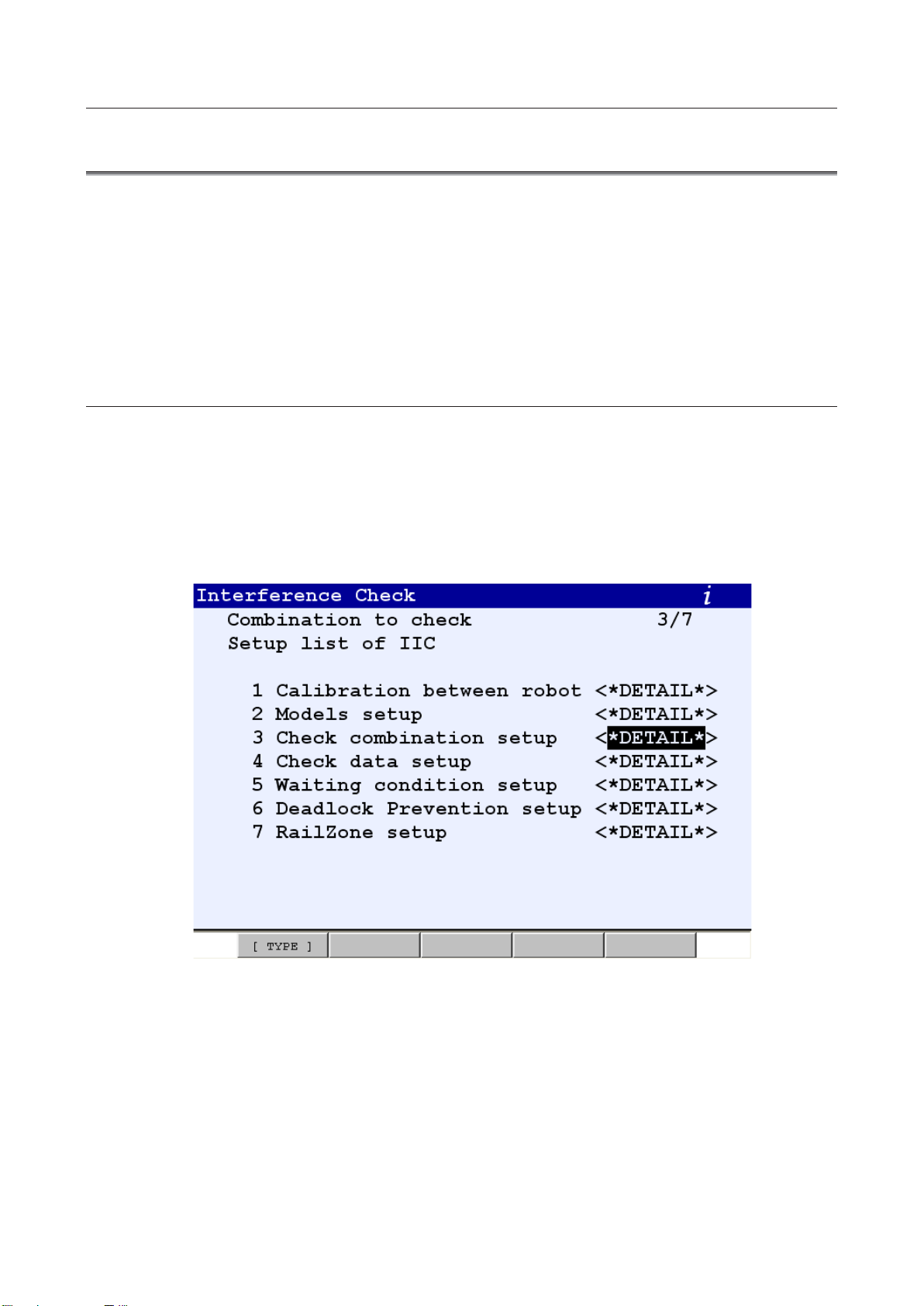
3 SETTINGS MAROBBI8204121E REV F
3.4 SETTING INTERFERENCE CHECK COMBINATIONS
To use the interference check function, a combination of target models must be set. For some
combinations the necessary signals must also be set.
Combination of models
Set a combination of models for which the interference check function is to be operated. For a
combination, specify the types (robot including a hand/fixture) and numbers (group number/fixture
number) of target models and whether to enable or disable the combination. Up to 10 combinations can
be specified.
3.4.1 Setting a combination of models
The procedure for setting a combination is described below:
Procedure
1. Press the MENUS key to display the screen menu and select "SETUP".
2. Press the [TYPE] (F1) key and select "Interference". The setting list screen for the interference check
function appears.
Menu for Intelligent Interference Check
75
Page 94

MAROBBI8204121E REV F 3 SETTINGS
Menu for Basic Interference Check
3. Position the cursor on "3 Check combination setup <*DETAIL*>" and press the Enter key. The
Combination to check list screen appears.
The robot groups in the controller are described in Item1. The number indicates the group
number. The “RH” indicates Robot + Hand.
76
Page 95

3 SETTINGS MAROBBI8204121E REV F
After setting the host name, turn the power off, then on again.
4. Position the cursor on the combination to be set and set the following items:
Cursoring to Host name and pressing F4 [CHOICE] brings up the valid host name list. Always set
the host name for every combination being used. For Robot+Hand the host name can be another
controller or the current controller if multiple robot groups exist on the controller. For all other
objects, fixtures, critical zones, virtual fences, DO Only, and PLC DIN, you must set the host name
of the current controller.
To erase the host name select the first item.
Cursoring to the Item2 and pressing F4, [CHOICE] brings up the combination type selection menu.
77
Page 96

MAROBBI8204121E REV F 3 SETTINGS
CHOICE menu for Intelligent Interference Check
There are six combination types that can be used in Intelligent Interference Check
1. Robot + Hand
2. Fixture
3. Critical Zone
4. Virtual Fence
5. DO Only
6. PLC DIN
One robot in the controller is always used as one of the combination pair. The other combination must
be one of the items described above. The screen will change to indicate the model type selected.
CHOICE menu for Basic Interference Check
78
Page 97

3 SETTINGS MAROBBI8204121E REV F
There are five combination types that can be used in Basic Interference Check
1. Fixture
2. Critical Zone
3. Virtual Fence
4. DO Only
5. PLC DIN
One robot in the controller is always used as one of the combination pair. The other combination must
be one of the items described above. The screen will change to indicate the model type selected.
3.4.1.1 Setting up combination for Robot + Hand
This function is only available for Intelligent Interference Check
1. Position the cursor on the number following “Rob+Hnd”. Set this to match the group number of the
robot.
79
Page 98

MAROBBI8204121E REV F 3 SETTINGS
2. Position the cursor on the line of a combination for which signals are to be assigned and press the
[DETAIL] (F2) key. The signal setting screen appears.
(In this example, the disable signal is set.)
Disable signal
Assign an input signal for each specified combination. When the specified signal is onɿɿ, the
approach deterrence function does not operate for the combination. Set a signal with
associating it with the clamp signal for the fixture. A DI, WI, or RI signal can be specified. If
no disable signal is defined for a combination, the approach deterrence function always
operates for the combination.
80
Page 99

3 SETTINGS MAROBBI8204121E REV F
Approach deterrence signal
The approach deterrence signal is turned on when the combination enters in the approach
deterrence status.
A DO, RO, or WO signal can be set.
If the index is set to 0, the approach deterrence signal is not output.
Temporary disable signal
The temporary disable signal is on when the approach deterrence function is temporarily
disabled for the combination. For details of when this signal is turned on and off and the
approach deterrence instructions, see Section 3.1, " APPROACH DETERRENCE FUNCTION
ENABLE/DISABLE INSTRUCTION."
A DO, RO, or WO signal can be set. If the index is set to 0, the temporary disable signal
3. Position the cursor on the type of signal and press the [CHOICE] (F4) key. The signals, which can be
selected, are displayed to set a signal
4. Select the type of input to be used for this signal and directly enter a signal assignment number.
When this value is set to 0, the corresponding signal is always off.
81
Page 100

MAROBBI8204121E REV F 3 SETTINGS
After setting the host name, turn the power off, then on again.
5. Select the type of output to be used for this signal and directly enter a signal assignment number.
Pressing the PREV key will bring you back to the Combination To Check main menu.
If the item is not yet enabled, cursor to the last column and press F4, ENABLED.
Select the host name of the controller for the other robot.
To erase the host name, select option 1.
82
 Loading...