

Page 1

GE Fanuc Automation
Computer Numerical Control Products
Series 15 / 150 – Model B
Connection Manual (Hardware)
GFZ-62073E/04 November 1998
Page 2

Warnings, Cautions, and Notes
as Used in this Publication
Warning notices are used in this publication to emphasize that hazardous voltages, currents,
temperatures, or other conditions that could cause personal injury exist in this equipment or
may be associated with its use.
In situations where inattention could cause either personal injury or damage to equipment, a
Warning notice is used.
Caution notices are used where equipment might be damaged if care is not taken.
GFL-001
Warning
Caution
Note
Notes merely call attention to information that is especially significant to understanding and
operating the equipment.
This document is based on information available at the time of its publication. While efforts
have been made to be accurate, the information contained herein does not purport to cover all
details or variations in hardware or software, nor to provide for every possible contingency in
connection with installation, operation, or maintenance. Features may be described herein
which are not present in all hardware and software systems. GE Fanuc Automation assumes
no obligation of notice to holders of this document with respect to changes subsequently made.
GE Fanuc Automation makes no representation or warranty, expressed, implied, or statutory
with respect to, and assumes no responsibility for the accuracy, completeness, sufficiency, or
usefulness of the information contained herein. No warranties of merchantability or fitness for
purpose shall apply.
©Copyright 1998 GE Fanuc Automation North America, Inc.
All Rights Reserved.
Page 3

B–62073E/04
DEFINITION OF WARNING, CAUTION, AND NOTE
DEFINITION OF WARNING, CAUTION, AND NOTE
This manual includes safety precautions for protecting the user and preventing damage to the
machine. Precautions are classified into W arning and Caution according to their bearing on safety.
Also, supplementary information is described as a Note. Read the Warning, Caution, and Note
thoroughly before attempting to use the machine.
WARNING
Applied when there is a danger of the user being injured or when there is a danger of both the user
being injured and the equipment being damaged if the approved procedure is not observed.
CAUTION
Applied when there is a danger of the equipment being damaged, if the approved procedure is not
observed.
NOTE
The Note is used to indicate supplementary information other than Warning and Caution.
`
Read this manual carefully, and store it in a safe place.
s–1
Page 4

B–62073E/04
Table of Contents
DEFINITION OF WARNING, CAUTION, AND NOTE s–1. . . . . . . . . . . . . . . . . . . . . . . . . . . . .
1. GENERAL 1. . . . . . . . . . . . . . . . . . . . . . . . . . . . . . . . . . . . . . . . . . . . . . . . . . . . . . . . . . . . . . . . . . .
2. CONFIGURATION 4. . . . . . . . . . . . . . . . . . . . . . . . . . . . . . . . . . . . . . . . . . . . . . . . . . . . . . . . . . . .
3. INSTALLATION 6. . . . . . . . . . . . . . . . . . . . . . . . . . . . . . . . . . . . . . . . . . . . . . . . . . . . . . . . . . . . . .
3.1 ENVIRONMENTAL REQUIREMENTS 7. . . . . . . . . . . . . . . . . . . . . . . . . . . . . . . . . . . . . . . . . . . . . . .
3.1.1 Cabinet Exterior Environmental Requirements 7. . . . . . . . . . . . . . . . . . . . . . . . . . . . . . . . . . . . . .
3.1.2 Installation Conditions of the CNC Inside Cabinet and Servo Unit 8. . . . . . . . . . . . . . . . . . . . . . .
3.2 POWER CAPACITY 9. . . . . . . . . . . . . . . . . . . . . . . . . . . . . . . . . . . . . . . . . . . . . . . . . . . . . . . . . . . . . . .
3.3 CABINET DESIGN AND INSTALLATION CONDITIONS OF
THE MACHINE TOOL MAGNETIC 10. . . . . . . . . . . . . . . . . . . . . . . . . . . . . . . . . . . . . . . . . . . . . . . . .
3.4 THERMAL DESIGN OF THE CABINET 13. . . . . . . . . . . . . . . . . . . . . . . . . . . . . . . . . . . . . . . . . . . . .
3.4.1 Temperature Rise within the Cabinet 13. . . . . . . . . . . . . . . . . . . . . . . . . . . . . . . . . . . . . . . . . . . . .
3.4.2 Cooling by Heat Exchanger 13. . . . . . . . . . . . . . . . . . . . . . . . . . . . . . . . . . . . . . . . . . . . . . . . . . . .
3.4.3 Heat Loss of Each Unit 14. . . . . . . . . . . . . . . . . . . . . . . . . . . . . . . . . . . . . . . . . . . . . . . . . . . . . . . .
3.5 INSTALLING THE HEAT EXCHANGER 16. . . . . . . . . . . . . . . . . . . . . . . . . . . . . . . . . . . . . . . . . . . . .
3.5.1 Cooling Fin A/B/C 16. . . . . . . . . . . . . . . . . . . . . . . . . . . . . . . . . . . . . . . . . . . . . . . . . . . . . . . . . . .
3.5.2 Heat Exchanger for CRT/MDI Unit 21. . . . . . . . . . . . . . . . . . . . . . . . . . . . . . . . . . . . . . . . . . . . . .
3.5.3 The Heat Pipe Type Heat Exchanger 24. . . . . . . . . . . . . . . . . . . . . . . . . . . . . . . . . . . . . . . . . . . . .
3.5.3.1 Installation 24. . . . . . . . . . . . . . . . . . . . . . . . . . . . . . . . . . . . . . . . . . . . . . . . . . . . . . . . . . . . . . . . . .
3.5.3.2 Maintenance 27. . . . . . . . . . . . . . . . . . . . . . . . . . . . . . . . . . . . . . . . . . . . . . . . . . . . . . . . . . . . . . . .
3.6 ACTION AGAINST NOISE 30. . . . . . . . . . . . . . . . . . . . . . . . . . . . . . . . . . . . . . . . . . . . . . . . . . . . . . . .
3.6.1 Separating Signal Lines 30. . . . . . . . . . . . . . . . . . . . . . . . . . . . . . . . . . . . . . . . . . . . . . . . . . . . . . .
3.6.2 Ground 31. . . . . . . . . . . . . . . . . . . . . . . . . . . . . . . . . . . . . . . . . . . . . . . . . . . . . . . . . . . . . . . . . . . . .
3.6.3 Grounding Each Unit 33. . . . . . . . . . . . . . . . . . . . . . . . . . . . . . . . . . . . . . . . . . . . . . . . . . . . . . . . .
3.6.4 Noise Suppressor 36. . . . . . . . . . . . . . . . . . . . . . . . . . . . . . . . . . . . . . . . . . . . . . . . . . . . . . . . . . . . .
3.6.5 Cable Clamp and Shield Processing 37. . . . . . . . . . . . . . . . . . . . . . . . . . . . . . . . . . . . . . . . . . . . . .
3.7 CONTROL UNIT 40. . . . . . . . . . . . . . . . . . . . . . . . . . . . . . . . . . . . . . . . . . . . . . . . . . . . . . . . . . . . . . . . .
3.7.1 Configuration and Installation of the Control Unit 40. . . . . . . . . . . . . . . . . . . . . . . . . . . . . . . . . .
3.7.2 Battery for Memory Backup 44. . . . . . . . . . . . . . . . . . . . . . . . . . . . . . . . . . . . . . . . . . . . . . . . . . . .
3.7.3 Replacing the Battery 45. . . . . . . . . . . . . . . . . . . . . . . . . . . . . . . . . . . . . . . . . . . . . . . . . . . . . . . . .
3.8 CABLE LEAD–IN DIAGRAM 47. . . . . . . . . . . . . . . . . . . . . . . . . . . . . . . . . . . . . . . . . . . . . . . . . . . . . .
3.8.1 Configuration of Control Unit Connectors 47. . . . . . . . . . . . . . . . . . . . . . . . . . . . . . . . . . . . . . . . .
3.8.2 Cable Lead–in for Stand–alone Cabinet A 67. . . . . . . . . . . . . . . . . . . . . . . . . . . . . . . . . . . . . . . . .
3.8.3 Cable Lead–in for Stand–alone Cabinet B 68. . . . . . . . . . . . . . . . . . . . . . . . . . . . . . . . . . . . . . . . .
3.8.4 Cable Lead–in for Additional Cabinet A 69. . . . . . . . . . . . . . . . . . . . . . . . . . . . . . . . . . . . . . . . . .
3.9 MAINTENANCE AREA 70. . . . . . . . . . . . . . . . . . . . . . . . . . . . . . . . . . . . . . . . . . . . . . . . . . . . . . . . . . .
3.9.1 Maintenance Area for Self–standing A Type Cabinet 70. . . . . . . . . . . . . . . . . . . . . . . . . . . . . . . .
3.9.2 Maintenance Area for Self–standing B Type Cabinet 71. . . . . . . . . . . . . . . . . . . . . . . . . . . . . . . .
3.9.3 Maintenance Area for Additional Cabinet A 72. . . . . . . . . . . . . . . . . . . . . . . . . . . . . . . . . . . . . . .
4. TOTAL CONNECTION 73. . . . . . . . . . . . . . . . . . . . . . . . . . . . . . . . . . . . . . . . . . . . . . . . . . . . . .
4.1 CONNECTION DIAGRAM FOR SERIES 15–TB/TTB/MB/TFB/TTFB/MFB,
SERIES 150–TB/MB/TTB (IN CASE OF SERIAL SPINDLE) 74. . . . . . . . . . . . . . . . . . . . . . . . . . . . .
4.1.1 Connection Diagram for Series 15–TB/TTB/MB/TFB/TTFB/MFB, Series 150–TB/MB/TTB
(When LCD/MDI Unit with Built–in Graphic Functions is not Used) 74. . . . . . . . . . . . . . . . . . .
4.1.2 Connection Diagram for Series 15–TB/TTB/MB
(When LCD/MDI Unit with Built–in Graphic Functions is Used) 77. . . . . . . . . . . . . . . . . . . . . .
c–1
Page 5

TABLE OF CONTENTS
4.2 CONNECTION DIAGRAM FOR SERIES 15–TB/TTB/MB/TFB/TTFB/MFB,
SERIES 150–TB/MB/TTB (IN CASE OF ANALOG SPINDLE) 80. . . . . . . . . . . . . . . . . . . . . . . . . . .
4.3 CONNECTION DIAGRAM FOR SERIES 15–MB OR SERIES 150–MB
(IN CASE OF MULTIPLE AXIS) 83. . . . . . . . . . . . . . . . . . . . . . . . . . . . . . . . . . . . . . . . . . . . . . . . . . . .
4.3.1 Control Unit 84. . . . . . . . . . . . . . . . . . . . . . . . . . . . . . . . . . . . . . . . . . . . . . . . . . . . . . . . . . . . . . . .
4.3.2 Additional Cabinet (In Case of Serial Spindle Interface) 85. . . . . . . . . . . . . . . . . . . . . . . . . . . . . .
4.3.3 Additional Cabinet (In Case of Analog Spindle Interface) 86. . . . . . . . . . . . . . . . . . . . . . . . . . . .
4.3.4 Connection Between the Control Unit and Additional Locker 88. . . . . . . . . . . . . . . . . . . . . . . . .
4.4 CONNECTION DIAGRAM FOR SERIES 15–B (IN CASE OF MMC–II) 89. . . . . . . . . . . . . . . . . . . .
4.5 CONNECTION DIAGRAM FOR SERIES 15–B (IN CASE OF MMC–III) 91. . . . . . . . . . . . . . . . . . .
4.6 CONNECTION DIAGRAM FOR MMC–IV 92. . . . . . . . . . . . . . . . . . . . . . . . . . . . . . . . . . . . . . . . . . .
B–62073E/04
5. POWER SUPPLY UNIT AND INPUT UNIT CONNECTION 94. . . . . . . . . . . . . . . . . . . . . . .
5.1 POWER SUPPLY UNIT PANEL LAYOUT 95. . . . . . . . . . . . . . . . . . . . . . . . . . . . . . . . . . . . . . . . . . . .
5.2 CONNECTING THE POWER SUPPLY UNIT 97. . . . . . . . . . . . . . . . . . . . . . . . . . . . . . . . . . . . . . . . .
5.2.1 When an Input Unit is not Used 97. . . . . . . . . . . . . . . . . . . . . . . . . . . . . . . . . . . . . . . . . . . . . . . . .
5.2.2 When an Input Unit is Used 100. . . . . . . . . . . . . . . . . . . . . . . . . . . . . . . . . . . . . . . . . . . . . . . . . . .
5.2.3 When AC Output Terminals for Which Power On/Off is Controlled are Insufficient 103. . . . . . .
5.2.4 Power ON Sequence 104. . . . . . . . . . . . . . . . . . . . . . . . . . . . . . . . . . . . . . . . . . . . . . . . . . . . . . . . .
5.2.5 Power OFF Sequence 104. . . . . . . . . . . . . . . . . . . . . . . . . . . . . . . . . . . . . . . . . . . . . . . . . . . . . . . .
5.3 CONNECTION OF INPUT UNIT FOR STANDALONE CABINET A 105. . . . . . . . . . . . . . . . . . . . .
5.3.1 Input Unit Layout 105. . . . . . . . . . . . . . . . . . . . . . . . . . . . . . . . . . . . . . . . . . . . . . . . . . . . . . . . . . .
5.3.2 Connection to Input Units (A14B–0076–B004, –B005, and –B008) 105. . . . . . . . . . . . . . . . . . . .
5.3.3 Connection to the Control Unit 109. . . . . . . . . . . . . . . . . . . . . . . . . . . . . . . . . . . . . . . . . . . . . . . . .
5.4 CONNECTION OF INPUT UNIT FOR STANDALONE CABINET B 110. . . . . . . . . . . . . . . . . . . . .
5.4.1 Input Unit Layout 110. . . . . . . . . . . . . . . . . . . . . . . . . . . . . . . . . . . . . . . . . . . . . . . . . . . . . . . . . . .
5.4.2 Connection to Input Unit (A14B–0076–B411) 111. . . . . . . . . . . . . . . . . . . . . . . . . . . . . . . . . . . . .
5.4.3 Connection to Control Unit 114. . . . . . . . . . . . . . . . . . . . . . . . . . . . . . . . . . . . . . . . . . . . . . . . . . . .
5.5 CONNECTION OF INPUT UNIT FOR ADDITIONAL CABINET A 115. . . . . . . . . . . . . . . . . . . . . .
5.5.1 Input Unit Layout 115. . . . . . . . . . . . . . . . . . . . . . . . . . . . . . . . . . . . . . . . . . . . . . . . . . . . . . . . . . .
5.5.2 Cable Connection
[Connection to the Input Unit (A02B–0075–J141, –J142, –J144, and –J145)] 116. . . . . . . . . . . .
6. CONNECTION OF I/O UNITS TO MACHINE INTERFACE 120. . . . . . . . . . . . . . . . . . . . . .
6.1 OUTLINE 121. . . . . . . . . . . . . . . . . . . . . . . . . . . . . . . . . . . . . . . . . . . . . . . . . . . . . . . . . . . . . . . . . . . . . .
6.2 CONNECTION OF THE FANUC I/O LINK 123. . . . . . . . . . . . . . . . . . . . . . . . . . . . . . . . . . . . . . . . . .
6.2.1 Connection of FANUC I/O Link by Electric Cable 125. . . . . . . . . . . . . . . . . . . . . . . . . . . . . . . . .
6.2.2 Connection of FANUC I/O Link by Optical Fiber Cable 126. . . . . . . . . . . . . . . . . . . . . . . . . . . . .
6.3 CONNECTION OF THE FANUC I/O UNIT–MODEL A 131. . . . . . . . . . . . . . . . . . . . . . . . . . . . . . . .
6.3.1 Structure of FANUC I/O Unit–MODEL A 131. . . . . . . . . . . . . . . . . . . . . . . . . . . . . . . . . . . . . . . .
6.3.2 Outer Dimensions 132. . . . . . . . . . . . . . . . . . . . . . . . . . . . . . . . . . . . . . . . . . . . . . . . . . . . . . . . . . .
6.3.3 Mounting and Dismounting Modules 132. . . . . . . . . . . . . . . . . . . . . . . . . . . . . . . . . . . . . . . . . . . .
6.3.4 Connection Diagram 134. . . . . . . . . . . . . . . . . . . . . . . . . . . . . . . . . . . . . . . . . . . . . . . . . . . . . . . . .
6.3.5 Connecting Input Power Source 135. . . . . . . . . . . . . . . . . . . . . . . . . . . . . . . . . . . . . . . . . . . . . . . .
6.3.6 Grounding 136. . . . . . . . . . . . . . . . . . . . . . . . . . . . . . . . . . . . . . . . . . . . . . . . . . . . . . . . . . . . . . . . .
6.3.7 Connecting Signal Cables 138. . . . . . . . . . . . . . . . . . . . . . . . . . . . . . . . . . . . . . . . . . . . . . . . . . . . .
6.3.8 Connecting with I/O Modules 141. . . . . . . . . . . . . . . . . . . . . . . . . . . . . . . . . . . . . . . . . . . . . . . . . .
c–2
Page 6

B–62073E/04
6.4 CONNECTING THE CONNECTION UNIT 147. . . . . . . . . . . . . . . . . . . . . . . . . . . . . . . . . . . . . . . . . .
6.5 CONNECTION OF OPERATOR’S PANEL CONNECTION UNIT 175. . . . . . . . . . . . . . . . . . . . . . . .
6.6 CONNECTION OF SOURCE OUTPUT OPERATOR’S PANEL CONNECTION UNIT 189. . . . . . .
6.7 ADDRESS–FIXED SIGNALS 207. . . . . . . . . . . . . . . . . . . . . . . . . . . . . . . . . . . . . . . . . . . . . . . . . . . . .
TABLE OF CONTENTS
6.3.9 Digital Input/Output Module 143. . . . . . . . . . . . . . . . . . . . . . . . . . . . . . . . . . . . . . . . . . . . . . . . . .
6.3.10 Correspondence between I/O Signals and Addresses in a Module 145. . . . . . . . . . . . . . . . . . . . .
6.3.11 Number of I/O Points for I/O Unit–MODEL A 145. . . . . . . . . . . . . . . . . . . . . . . . . . . . . . . . . . . .
6.4.1 Connecting Connection Unit 1 and Connection Unit 2 149. . . . . . . . . . . . . . . . . . . . . . . . . . . . . .
6.4.2 Input Signal Regulations for the Connection Unit 151. . . . . . . . . . . . . . . . . . . . . . . . . . . . . . . . . .
6.4.3 Output Signal Regulations for the Connection Unit 153. . . . . . . . . . . . . . . . . . . . . . . . . . . . . . . . .
6.4.4 Connector Pin Assignment for the Connection Unit 154. . . . . . . . . . . . . . . . . . . . . . . . . . . . . . . .
6.4.5 Details of the Connection between the Connection Unit and the Machine 156. . . . . . . . . . . . . . .
6.4.6 External View of the Connection Unit 174. . . . . . . . . . . . . . . . . . . . . . . . . . . . . . . . . . . . . . . . . . .
6.5.1 Input Signal Regulations for the Operator’s Panel Connection Unit 176. . . . . . . . . . . . . . . . . . . .
6.5.2 Output Signal Regulations for the Operator’s Panel Connection Unit 177. . . . . . . . . . . . . . . . . .
6.5.3 Connector Layout for Operator’s Panel Connection Unit 179. . . . . . . . . . . . . . . . . . . . . . . . . . . .
6.5.4 Details of the Connection between the Operator’s Panel Connection Unit and the Machine 181.
6.5.5 External View of Operator ’s Panel Connection Unit 188. . . . . . . . . . . . . . . . . . . . . . . . . . . . . . . .
6.6.1 Source Output Operator’s Panel Connection Unit Input Signal Standard 190. . . . . . . . . . . . . . . .
6.6.2 Output Signal Standard for Source Output Operator’s Panel Connection Unit 192. . . . . . . . . . . .
6.6.3 ALARM LEDs on Source Output Operator’s Panel Connection Unit 195. . . . . . . . . . . . . . . . . . .
6.6.4 Connector Pin Assignment Addresses of Source Output
Operator ’s Panel Connection Unit 197. . . . . . . . . . . . . . . . . . . . . . . . . . . . . . . . . . . . . . . . . . . . . .
6.6.5 Details of Machine Side Connections of Source Output Operator’s Panel Connection Unit 199.
6.6.6 External Dimensions of Source Output Operator’s Panel Connection Unit 206. . . . . . . . . . . . . .
7. CONNECTION TO CNC PERIPHERALS 208. . . . . . . . . . . . . . . . . . . . . . . . . . . . . . . . . . . . .
7.1 CRT/MDI UNIT INTERFACE 209. . . . . . . . . . . . . . . . . . . . . . . . . . . . . . . . . . . . . . . . . . . . . . . . . . . . .
7.1.1 Outline 209. . . . . . . . . . . . . . . . . . . . . . . . . . . . . . . . . . . . . . . . . . . . . . . . . . . . . . . . . . . . . . . . . . . .
7.1.2 9″ CRT or 9″ PDP Display Interface (CE Marking Non–compliant) 214. . . . . . . . . . . . . . . . . . . .
7.1.3 9″ CRT or PDP Display Interface (CE Marking Compliant) 216. . . . . . . . . . . . . . . . . . . . . . . . . .
7.1.4 14″ Analog CRT, 10.4″ LCD, 9.5″ LCD Display Interface
(CE Marking Compliant when MMC–IV is not Used) 218. . . . . . . . . . . . . . . . . . . . . . . . . . . . . .
7.1.5 14″ Analog CRT, 10.4″ LCD, 9.5″ LCD Display Interface
(CE Marking Compliant when MMC–IV is Used) 220. . . . . . . . . . . . . . . . . . . . . . . . . . . . . . . . . .
7.1.6 10.4″ LCD Display Interface (CE Marking Compliant with Built–in Graphic Function) 222. . . .
7.1.7 Adjusting the Flat Display 224. . . . . . . . . . . . . . . . . . . . . . . . . . . . . . . . . . . . . . . . . . . . . . . . . . . .
7.1.8 Interface between MMC–IV Board and Option 1 Board (Video Signal) 225. . . . . . . . . . . . . . . . .
7.1.9 Keyboard Interface 226. . . . . . . . . . . . . . . . . . . . . . . . . . . . . . . . . . . . . . . . . . . . . . . . . . . . . . . . . .
7.1.10 Small 9″ Keyboard Interface 227. . . . . . . . . . . . . . . . . . . . . . . . . . . . . . . . . . . . . . . . . . . . . . . . . . .
7.1.11 Interface between MMC–III Board and Option 1 Board (Video Signal) 228. . . . . . . . . . . . . . . . .
7.2 I/O DEVICE INTERFACE 229. . . . . . . . . . . . . . . . . . . . . . . . . . . . . . . . . . . . . . . . . . . . . . . . . . . . . . . .
7.2.1 RS–232–C Serial Port 229. . . . . . . . . . . . . . . . . . . . . . . . . . . . . . . . . . . . . . . . . . . . . . . . . . . . . . . .
7.2.2 PPR Connection 230. . . . . . . . . . . . . . . . . . . . . . . . . . . . . . . . . . . . . . . . . . . . . . . . . . . . . . . . . . . .
7.2.3 Portable Tape Reader Connection 231. . . . . . . . . . . . . . . . . . . . . . . . . . . . . . . . . . . . . . . . . . . . . . .
7.2.4 FANUC Cassette Connection 232. . . . . . . . . . . . . . . . . . . . . . . . . . . . . . . . . . . . . . . . . . . . . . . . . .
7.2.5 Connection with the FANUC Handy File 233. . . . . . . . . . . . . . . . . . . . . . . . . . . . . . . . . . . . . . . . .
7.2.6 Connection of Tape Reader Without Reels 234. . . . . . . . . . . . . . . . . . . . . . . . . . . . . . . . . . . . . . . .
7.2.7 Connection of Tape Reader with Reels 235. . . . . . . . . . . . . . . . . . . . . . . . . . . . . . . . . . . . . . . . . .
7.2.8 RS–422 Serial Port 236. . . . . . . . . . . . . . . . . . . . . . . . . . . . . . . . . . . . . . . . . . . . . . . . . . . . . . . . . .
c–3
Page 7

TABLE OF CONTENTS
7.3 MANUAL PULSE GENERATOR INTERFACE 238. . . . . . . . . . . . . . . . . . . . . . . . . . . . . . . . . . . . . . .
7.4 REMOTE BUFFER INTERFACE (RS–232–C) 240. . . . . . . . . . . . . . . . . . . . . . . . . . . . . . . . . . . . . . . .
7.5 REMOTE BUFFER INTERFACE (RS–422) 242. . . . . . . . . . . . . . . . . . . . . . . . . . . . . . . . . . . . . . . . . .
7.6 HIGH–SPEED DI SIGNAL INTERFACE 244. . . . . . . . . . . . . . . . . . . . . . . . . . . . . . . . . . . . . . . . . . . .
7.7 CONNECTION OF REFERENCE POSITION APPROACH SIGNAL 247. . . . . . . . . . . . . . . . . . . . . .
7.8 DNC INTERFACE 248. . . . . . . . . . . . . . . . . . . . . . . . . . . . . . . . . . . . . . . . . . . . . . . . . . . . . . . . . . . . . . .
7.8.1 DNC1 Interface 248. . . . . . . . . . . . . . . . . . . . . . . . . . . . . . . . . . . . . . . . . . . . . . . . . . . . . . . . . . . . .
7.8.2 DNC2 Interface (RS–232–C) 250. . . . . . . . . . . . . . . . . . . . . . . . . . . . . . . . . . . . . . . . . . . . . . . . . .
7.8.3 DNC2 Interface (RS422) 251. . . . . . . . . . . . . . . . . . . . . . . . . . . . . . . . . . . . . . . . . . . . . . . . . . . . . .
7.9 SPINDLE INTERFACE 252. . . . . . . . . . . . . . . . . . . . . . . . . . . . . . . . . . . . . . . . . . . . . . . . . . . . . . . . . . .
7.9.1 Serial Spindle Interface (S Series Spindle) 254. . . . . . . . . . . . . . . . . . . . . . . . . . . . . . . . . . . . . . . .
7.9.2 Serial Spindle Interface (α Series) 255. . . . . . . . . . . . . . . . . . . . . . . . . . . . . . . . . . . . . . . . . . . . . .
7.9.3 Analog Spindle Interface 256. . . . . . . . . . . . . . . . . . . . . . . . . . . . . . . . . . . . . . . . . . . . . . . . . . . . .
7.9.4 Pulse Coder Interface 257. . . . . . . . . . . . . . . . . . . . . . . . . . . . . . . . . . . . . . . . . . . . . . . . . . . . . . . .
7.10 SERVO INTERFACE 259. . . . . . . . . . . . . . . . . . . . . . . . . . . . . . . . . . . . . . . . . . . . . . . . . . . . . . . . . . . .
7.10.1 Outline 259. . . . . . . . . . . . . . . . . . . . . . . . . . . . . . . . . . . . . . . . . . . . . . . . . . . . . . . . . . . . . . . . . . . .
7.10.2 Servo Amp Interface 260. . . . . . . . . . . . . . . . . . . . . . . . . . . . . . . . . . . . . . . . . . . . . . . . . . . . . . . . .
7.10.3 Serial Pulse Coder Interface 263. . . . . . . . . . . . . . . . . . . . . . . . . . . . . . . . . . . . . . . . . . . . . . . . . . .
7.10.4 Linear Scale Interface (A/B/Z Signal Interface) 269. . . . . . . . . . . . . . . . . . . . . . . . . . . . . . . . . . .
7.10.5 Linear Scale Interface (Serial Interface) 271. . . . . . . . . . . . . . . . . . . . . . . . . . . . . . . . . . . . . . . . . .
7.10.6 APC Battery Interface 272. . . . . . . . . . . . . . . . . . . . . . . . . . . . . . . . . . . . . . . . . . . . . . . . . . . . . . . .
7.10.7 Hybrid–control Connections 273. . . . . . . . . . . . . . . . . . . . . . . . . . . . . . . . . . . . . . . . . . . . . . . . . . .
7.11 GENERAL–PURPOSE ANALOG VOLTAGE INPUT INTERFACE 274. . . . . . . . . . . . . . . . . . . . . . .
7.12 CONNECTION BETWEEN THE SERIES 15–B (MMC–II) AND PERIPHERAL UNITS 275. . . . . .
7.13 CONNECTION WITH AN EXTERNAL DEVICE USING THE RS–422 INTERFACE
FOR SERIES 15–B (MMC–II) 277. . . . . . . . . . . . . . . . . . . . . . . . . . . . . . . . . . . . . . . . . . . . . . . . . . . . .
7.14 CONNECTION WITH A PRINTER USING THE CENTRONICS INTERFACE
FOR FANUC SERIES 15–B (MMC–II) 279. . . . . . . . . . . . . . . . . . . . . . . . . . . . . . . . . . . . . . . . . . . . . .
7.15 CONNECTION WITH AN EXTENSION ADAPTOR UNIT
FOR FANUC SERIES 15–B (MMC–II) 281. . . . . . . . . . . . . . . . . . . . . . . . . . . . . . . . . . . . . . . . . . . . . .
7.16 CONNECTION WITH A HARD DISK UNIT FOR FANUC SERIES 15–B (MMC–II) 283. . . . . . . .
7.17 CONNECTION WITH A FLOPPY DISK UNIT FOR FANUC SERIES 15–B (MMC–II) 287. . . . . . .
7.18 RS–232–C SERIAL PORT (MMC–III) 290. . . . . . . . . . . . . . . . . . . . . . . . . . . . . . . . . . . . . . . . . . . . . . .
7.19 OUTER HARD DISK INTERFACE (MMC–III) 292. . . . . . . . . . . . . . . . . . . . . . . . . . . . . . . . . . . . . . .
B–62073E/04
8. EMERGENCY STOP SIGNAL 294. . . . . . . . . . . . . . . . . . . . . . . . . . . . . . . . . . . . . . . . . . . . . . .
APPENDIX
A. LIST OF EXTERNAL DIMENSIONS 299. . . . . . . . . . . . . . . . . . . . . . . . . . . . . . . . . . . . . . . . .
B. EXTERNAL DIMENSIONS 302. . . . . . . . . . . . . . . . . . . . . . . . . . . . . . . . . . . . . . . . . . . . . . . . .
C. 20–PIN INTERFACE CONNECTORS AND CABLES 366. . . . . . . . . . . . . . . . . . . . . . . . . . .
D. ATTACHING THE CRT PROTECTIVE COVER 377. . . . . . . . . . . . . . . . . . . . . . . . . . . . . . . .
c–4
Page 8

B–62073E/04
1
1. GENERAL
GENERAL
Contents of this manual
How this manual is
organized
This manual describes the electrical and structural specifications required
for connecting the CNC control units, FANUC Series 15–MODEL
B/Series 150–MODEL B, with a machine tool, and covers the equipment
shown in the configuration diagram in Chapter 2. When using the CNC
control units, be sure to connect and install them following the
instructions in this manual. The manual outlines the units commonly used
for Fanuc CNC control units, that is, the I/O unit, servo motor, spindle
motor, and so on, and describes additional information on using these
units for the Series 15/150–B. Refer to individual manuals for the
detailed specifications of each unit.
Multiple models of Series 15/150–B products are provided so that they
correspond to various machine tools (lathe, machining center, etc.),
respectively . The description in this manual is common to these models.
Whenever each model has different restrictions, the abbreviation of the
model and notes are described. See the following table for the names and
abbreviations of the models described in this manual.
This manual comprises the following chapters and appendix.
1. GENERAL
This chapter. It describes the outline and organization of this manual,
names of models applied and other related manuals.
2. CONFIGURATION
This chapter describes the configuration of the electrical system of the
machine tool with which the CNC is used.
3. INSTALLATION
This chapter describes how to install the CNC.
4. TOTAL CONNECTION
This chapter shows the connection diagrams for the CNC and each
device.
5. POWER SUPPLY UNIT AND INPUT UNIT CONNECTION
This chapter describes the connection of the CNC to the power supply
unit and input unit.
6. CONNECTION OF I/O UNITS TO MACHINE INTERFACE
This chapter describes the connection of the CNC to the I/O unit to
machine interface.
1
Page 9
1. GENERAL
B–62073E/04
7. CONNECTION TO CNC PERIPHERALS
This chapter describes the connection of the CNC to peripherals.
APPENDIX
This appendix contains an explanation of the CNC control unit,
external dimensions of the display apparatus and details on the 20–pin
interface connectors and cables.
Applicable models
This manual can be used with the following models.
The abbreviated names may be used.
Product Name Abbreviations
FANUC Series 15–TB 15–TB
FANUC Series 15–TFB 15–TFB
FANUC Series 15TED–MODEL B–4 (*1) 15TED
FANUC Series 15TEE–MODEL B–4 (*1) 15TEE
FANUC Series 15TEF–MODEL B–4 (*1) 15TEF
FANUC Series 15–MB 15–MB
FANUC Series 15–MFB 15–MFB
FANUC Series 15MEK–MODEL B–4 (*1) 15MEK
FANUC Series 15MEL–MODEL B–4 (*1) 15MEL
FANUC Series 15–TTB 15–TTB
FANUC Series 15–TTFB 15–TTFB
FANUC Series 150–TB 150–TB
Series 15–B
FANUC Series 150–TTB 150–TTB
FANUC Series 150–MB 150–MB
Series 150–B
(*1)With 15TED, 15TEE, and 15TEF, some options are not available.
Moreover, the following PC boards cannot be used:
D
Sub–CPU board
D
RISC board
D
OSI ethernet board
(*2)The MMC board can be used only with the Series 150.
(*3)See FANUC MMC-IV Connection and Maintenance Manual
(B-62493E) for connection related to MMC-IV.
2
Page 10

B–62073E/04
1. GENERAL
Manuals related to
Series 15/150–MODEL B
List of manuals related to Series 15/150–MODEL B
FANUC Series 15–TB/TFB/TTB/TTFB DESCRIPTIONS B–62072E
FANUC Series 15/150–MODEL B For Machining Center DESCRIPTIONS B–62082E
FANUC Series 15/150–MODEL B CONNECTION MANUAL B–62073E *
FANUC Series 15/150–MODEL B CONNECTION MANUAL (BMI Interface) B–62073E–1
FANUC Series 15–MODEL B For Lathe OPERATOR’S MANUAL (Programming) B–62554E
FANUC Series 15–MODEL B For Lathe OPERATOR’S MANUAL (Operation) B–62554E–1
FANUC Series 15/150–MODEL B For Machining Center OPERATOR’S MANUAL (Programming) B–62564E
FANUC Series 15/150–MODEL B For Machining Center OPERATOR’S MANUAL (Operation) B–62564E–1
FANUC Series 15/150–MODEL B PARAMETER MANUAL B–62560E
FANUC Series 15/150–MODEL B MAINTENANCE MANUAL B–62075E
FANUC Series 15–MODEL B DESCRIPTIONS (Supplement for Remote Buf fer) B–62072E–1
FANUC Series 15–MODEL B PROGRAMMING MANUAL (Macro Compiler / Macro Executer) B–62073E–2
PMC
FANUC PMC–MODEL N/NA PROGRAMMING MANUAL (Ladder Language) B–61013E
FANUC PMC–MODEL NB/NB2 PROGRAMMING MANUAL (Ladder Language) B–61863E
FANUC PMC–MODEL N/NA PROGRAMMING MANUAL (C Language) B–61013E–2
FANUC PMC–MODEL NB PROGRAMMING MANUAL (C Language) B–61863E–1
FANUC PMC–MODEL N/NA
PROGRAMMING MANUAL (C Language – Tool Management Library)
Conversational Automatic Programming Function
CONVERSA TIONAL AUT OMATIC PROGRAMMING FUNCTION FOR MACHINING CENTER
(Series 15–MF/MFB) PROGRAMMING MANUAL
CONVERSA TIONAL AUT OMATIC PROGRAMMING FUNCTION FOR MACHINING CENTER
(Series 15–MF/MFB) OPERA TOR’S MANUAL
CONVERSA TIONAL AUT OMATIC PROGRAMMING FUNCTION FOR LA THE
(Series 15–TF/TTF/TFB/TTFB) OPERA TOR’S MANUAL
CONVERSA TIONAL AUT OMATIC PROGRAMMING FUNCTION II FOR LA THE
(Series 15–TFB/TTFB) OPERA T OR’S MANUAL
Tracing / Digitizing
FANUC Series 15–MB DESCRIPTIONS (Supplement for T racing / Digitizing) B–62472E
FANUC Series 15–MB CONNECTION MANUAL (Supplement for T racing / Digitizing) B–62473E
FANUC Series 15–MB OPERATOR’S MANUAL (Supplement for T racing / Digitizing) B–62474E
Gas, Laser Plasma Cutting Machine
FANUC Series 15–MB DESCRIPTIONS (FOR GAS, LASER PLASMA CUTTING MACHINE) B–62082EN–1
Multi–Teaching Function
FANUC Series 15–MB CONNECTION MANUAL (Multi–Teaching Function) B–62083E–1
Multiple–axis and Multiple–path Control Function
FANUC Series 15–TTB OPERATOR’S MANUAL
(Supplement Explanations for Multiple–axis and Multiple–path Control Function)
Manuals related to FANUC Series 15/150–MODEL B are as follows.
This manual is marked with an asterisk (*).
Manual Name
Specification
Number
B–61013E–4
B–61263E
B–61264E
B–61234E
B–61804E–2
B–62074E–1
3
Page 11

2. CONFIGURATION
CONFIGURATION
2
B–62073E/04
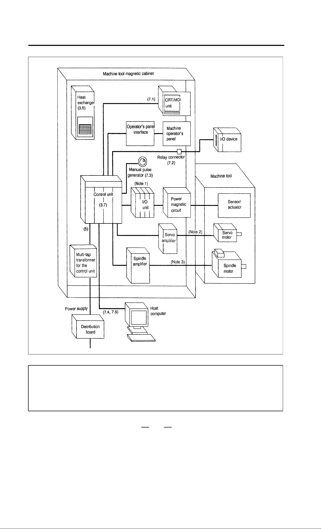
The following figure (see next page) shows the configuration of the
electrical system of the machine tool with which the Series 15–B is used.
This manual describes how to connect the units illustrated in this diagram.
The machine tool body, machine operator’s panel, power magnetic
circuit, and sensor/actuator are specific to the machine tool and are the
builder’s responsibility. This manual does not cover the internal
connection of these units to the machine tool.
The numbers in parentheses shown in the diagram are section references
for this manual.
4
Page 12
B–62073E/04
2. CONFIGURATION
(6.4, 6.5, 6.6)
(6.2, 6.3,
6.4, 6.7)
(7.10)
(7.9)
NOTE
1 Refer to the “FANUC I/O Unit–Model A Connecting Maintenance Manual (B–61813E).” or the
“FANUC I/O Unit–Model B Connecting Manual (B–62163E).”
2 Refer to the “FANUC AC Servo Motor α series Descriptions (B–65142E).”
3 Refer to the “FANUC AC Spindle Motor α series Descriptions (B–65152E).”
5
Page 13

3. INSTALLATION
INSTALLATION
3
B–62073E/04
6
Page 14
B–62073E/04
Ambient
Humidit
3.1
ENVIRONMENTAL REQUIREMENTS
3. INSTALLATION
3.1.1
Cabinet Exterior
Environmental
Requirements
The peripheral units, such as the control unit and CRT/MDI, have been
designed on the assumption that they are housed in closed cabinets. In
this manual “cabinet” refers to the following:
(1) Cabinet manufactured by the machine tool builder for housing the
control unit or peripheral units;
(2)Cabinet for housing the flexible turnkey system provided by F ANUC;
(3) Operation pendant, manufactured by the machine tool builder, for
housing the CRT/MDI unit or operator’s panel ; or
(4)Equivalent to the above.
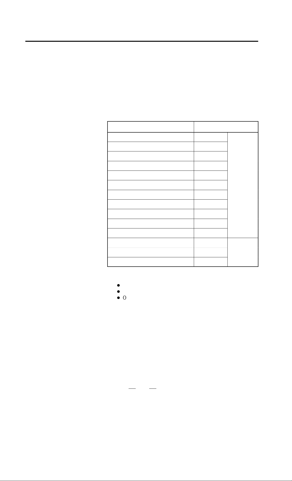
The environmental conditions when installing these cabinets shall
conform to the following table. Section 3.3 describes the installation and
design conditions of a cabinet satisfying these conditions.
Ambient
temperature
around cabinet
Change in
temperature
When a PCB
Conditions
In operation 0°C to 45°C 5°C to 40°C
In storage or
transportation
with internal
hard disk is not
mounted
–20°C to 60°C
1.1°C/minute
max.
When a PCB
with internal
hard disk is
mounted
0.3°C/minute
max.
y
Vibration
Environment
Relative humidity
Normal
Temporary
(within one
month)
In operation 0.5 G or less
In storage or
transportation
75% or less, no
condensation
allowed
Relative humidity
95% or less, no
condensation
allowed
Normal machine shop environment
(The environment must be
considered if the cabinets are in a
location where the concentration of
dust, coolant, and/or organic solvent
is relatively high.)
Relative humidity
10 to 75%, no
condensation
allowed
Relative humidity
10 to 90%, no
condensation
allowed
1.0 G or less
7
Page 15

3. INSTALLATION
3.1.2
Installation Conditions
of the CNC Inside
Cabinet and Servo Unit
B–62073E/04
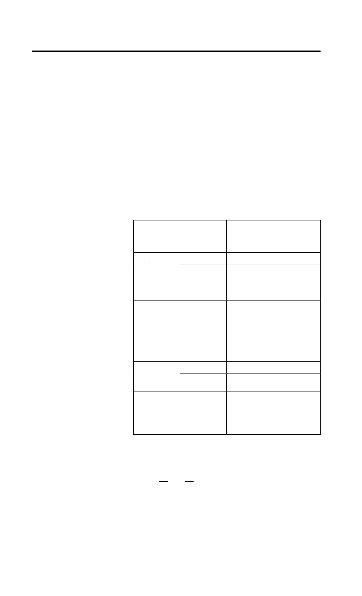
Ambient
temperature
Humidity Relative humidity: 95% or less, no condensation allowed
Vibration In operation: 0.5 G or less
Environment Coolant, lubricants and chips must not splash these units.
In operation: 0 to 55°C
(when a PCB with internal hard disk is not mounted)
In operation: 5 to 50°C
(when a PCB with internal hard disk is mounted)
In storage and transportation: –20 to 60°C
(when a PCB with internal hard disk is not mounted)
Relative humidity: 75% or less, no condensation allowed
(when a PCB with internal hard disk is mounted)
8
Page 16

B–62073E/04
Power ca acity of the
3. INSTALLATION
3.2
POWER CAPACITY
The power capacity of the CNC control unit, which in this section means
the specification required for the power supply , is obtained by adding the
power capacity of the control section and the power capacity of the servo
section.
The power capacity of the control section includes the power capacity of
the control unit, CRT/MDI, I/O unit, and operator’s panel interface.
Power capacity of the
control section
Power capacity of the
servo section
When power supply Al is used. 0.4 KV A
When power supply BI is used. 1 KV A
Depends on servo motor type.
9
Page 17

3. INSTALLATION
B–62073E/04
3.3
CABINET DESIGN
AND INST ALLATION
CONDITIONS OF THE
MACHINE TOOL
MAGNETIC
When a cabinet is designed, it must satisfy the environmental conditions
described in Section 3.1. In addition, the magnetic interference on the
CRT screen, noise resistance, and maintenance requirements must be
considered. The cabinet is design must meet the following conditions :
(1)The cabinet must be fully closed.
The cabinet must be designed to prevent the entry of airborne dust,
coolant, and organic solvent.
(2)The cabinet must be designed to maintain a difference in temperature
of 10°C or less between the air in the cabinet and the outside air as the
temperature in the cabinet increases.
See Section 3.4 for the details on thermal design of the cabinet.
(3) A closed cabinet must be equipped with a fan to circulate the air
within.
The fan must be adjusted so that the air moves at 0.5 m/sec along the
surface of each installed unit.
Caution: If the air blows directly from the fan to the unit, dust easily
abheres to the unit. This may cause the unit to fail.
(4)For the air to move easily, a clearance of 100 mm is required between
each unit and the wall of the cabinet.
(5) Packing materials must be used for the cable port and the door in
oreder to seal the cabinet.
Because the CRT unit uses a voltage of approximatery 11 KV to 20
KV, airborne dust gathers easily . If the cabinet is insuf ficiently sealed,
dust passes through the gap and abheres to the unit. This may cause
the insulation of the unit to deteriorate.
Acceptable packing materials:
D
Epton sealer No. 686, Nitto Industry Co., Ltd.
D
Polyurethane foam (ester) covered with vinyl chloride, Fuji
Rubber Co., Ltd.
(6) The CRT/MDI unit must be installed in a location where coolant
cannot be poured directly on it. The unit does have a dust–proof front
panel.
The front panel of the CRT/MDI unit is dust–proof. However, we do
not recommend installing the CRT/MDI unit in locations where
coolant directly splashes the front panel. Also, high–voltage is used
in the internal circuits of the CRT/MDI unit. Coolant entering the
CRT/MDI unit might cause serious trouble. The operation pendant
containing the cabinet and CRT/MDI unit is completely sealed, and
designed to prevent dirt, dust and coolant from entering. Pay particular
attention to preventing dust entering the CRT/MDI unit.
(7)Noise must be minimized.
As the machine and the CNC unit are reduced in size, the parts that
generate noise may be placed near noise–sensitive parts in the
magnetics cabinet.
The CNC unit is built to protect it from external noise. Cabinet design
to minimize noise generation and to prevent it from being transmitted
to the CNC unit is necessary. See section 3.6 for details of noise
elimination/management.
(8)The units must be installed or arranged in the cabinet so that they are
easy to inspect and maintain.
10
Page 18

B–62073E/04
3. INSTALLATION
(9)The CRT screen can be distorted by magnetic interference.
Arranging magnetic sources must be done with care.
If magnetic sources (such as transformers, fan motors,
electromagnetic contactors, solenoids, and relays) are located near the
CRT display, they frequently distort the display screen. To prevent
this, the CRT display and the magnetic sources generatlly must be kept
300 mm apart. If the CRT display and the magnetic sources are not
300 mm apart, the screen distortion may be suppressed by changing
the direction in which the magnetic sources are installed.
The magnetic intensity is not constant, and it is often increased by
magnetic interference from multiple magnetic sources interacting
with each other . As a result, simply keeping the CR T and the magnetic
sources 300 mm apart may not be enough to prevent the distortion.
If they cannot be kept apart, or if the CRT screen remains distorted
despite the distance, it may be necessary to cover the screen with a
magnetic shield.
(10)The installation conditions of the I/O unit must be satisfied.
T o obtain good ventilation in the module, the I/O unit must be installed
in the direction shown in the following figure. Clearances of 100 mm
or more both above and below the I/O unit are required for wiring and
ventilation.
Equipment radiating too much heat must not be put below the I/O unit.
Top
I/O base unit
(No screws or protrusions shall extend
from the bottom of this unit.)
Bottom
(11)If the CNC unit is installed at an elevation exceeding 1000 m, the upper
limit temperature of the CNC inside the cabinet at the environmental
conditions described in section 3.1 is subject to restrictions.
With each increase of 100 m above an elevation of 100 m, the upper
limit temperature is reduced by 1°C.
Example) When the CNC unit is installed at an elevation of 1750 m,
the allowable upper limit temperature of the CNC inside
the cabinet is calculated as follows:
55°C–1750/100 1.0°C+ 47.5°C
Accordingly the allowable temperature range is 0°C to
47.5°C
When a PCB with built–in hard disk is used, the installation elevation
is restricted as follows:
Standard elevation when in operation: –60 to 3,000 m
Standard elevation when not in operation: –60 to 12,000 m
(12)In unspecified frequencies, the CNC control unit or the hard disk itself
may resonate. If this happens, resonation may cause acceleration
beyond the allowable limits of the devices. Full check this after
installing the CNC control unit in the machine tool.
11
Page 19

3. INSTALLATION
B–62073E/04
NOTE
When a PCB with built–in hard disk is used, erroneous
operation or unexpected accidents may damage the data
stored on the hard disk even if the PCB is used under the
correct environment. To be extra sure, back up important
data from the hard disk.
If the power is turned OFF or a power interruption occurs
during accessing of the hard disk or while the operating
system is still running, data on the hard disk is more likely
to be damaged. Avoid this at all costs. Also, instruct the end
user to pay attention to this.
12
Page 20

B–62073E/04
3. INSTALLATION
3.4
THERMAL DESIGN OF THE CABINET
3.4.1
Temperature Rise
within the Cabinet
The purpose of the thermal design of the cabinet is to limit the difference
in temperature between the air in the cabinet and the outside air to 10°C
or less when the temperature in the cabinet increases.
The internal air temperature of the cabinet increases when the units and
parts installed in the cabinet generate heat. Since the generated heat is
radiated from the surface of the cabinet, the temperature of the air in the
cabinet and the outside air balance at certain heat levels. If the amount
of heat generated is constant, the larger the surface area of the cabinet, the
less the internal temperature rises. The thermal design of the cabinet
refers to calculating the heat generated in the cabinet, evaluating the
surface area of the cabinet, and enlarging that surface area by installing
heat exchangers in the cabinet, if necessary. Such a design method is
described in the following subsections.
The cooling capacity of a cabinet made of sheet metal is generally 6 W/°C
per 1 m
a cabinet having a surface area of 1 m
cabinet rises by 1°C. In this case the surface area of the cabinet refers to
the area useful in cooling , that is, the area obtained by subtracting the area
of the cabinet touching the floor from the total surface area of the cabinet.
There are two preconditions : The air in the cabinet must be circuited by
the fun, and the temperature of the air in the cabinet must be almost
constant.
To calculate the increase in temperature inside the cabinet, the heat loss
of the units to be installed must be checked. Section 3.4.3 lists the heat
losses of the units provided by FANUC. The heat loss of all other parts
in the cabinet must also be added. Let the obtained total heat loss be P
[W].
The following expression must then be satisfied to limit the difference in
temperature between the air in the cabinet and the outside air to 10°C or
less as the temperature in the cabinet rises:
For example, a cabinet having a surface area of 4 m
of 24 W/°C. To limit the internal temperature increase to 10°C under
these conditions, the internal heat must not exceed 240 W. If the actual
internal heat is 320 W, however, the temperature in the cabinet rises by
13°C or more. When this happens, the cooling capacity of the cabinet
must be improved using the heat exchanger described next.
2
surface area, that is, when the 6 W heat source is contained in
Internal heat loss P [W]x 6 [W/m
10 [°C] of rise in temperature
2
, the temperature of the air in the
2
·°C] surface area S [m2]
2
has a cooling capacity
3.4.2
Cooling by Heat
Exchanger
If the temperature rise cannot be limited to 10°C by the cooling capacity
of the cabinet, a heat exchanger must be added. The heat exchanger
forcibly applies the air from both the inside and outside of the cabinet to
the cooling fin to obtain effective cooling. The heat exchanger enlarges
the surface area. Section 3.5 explains five heat exchangers supplied by
FANUC. Select one of these according to the application.
If cooling fin A is used for the cabinet, the total cooling capacity of a
cabinet having a surface area of 4 m
as follows:
13
2
in the example above is improved
Page 21
3. INSTALLATION
3.4.3
Heat Loss of Each Unit
B–62073E/04
6 W/m2/°C 4 m2) 9.1 W/°C+ 33.1 W/°C
The calculated value verifies that even if the internal heat is 320 W, the
temperature rise can be limited to less than 10°C.
See Section 3.5 for installing the heat exchanger.
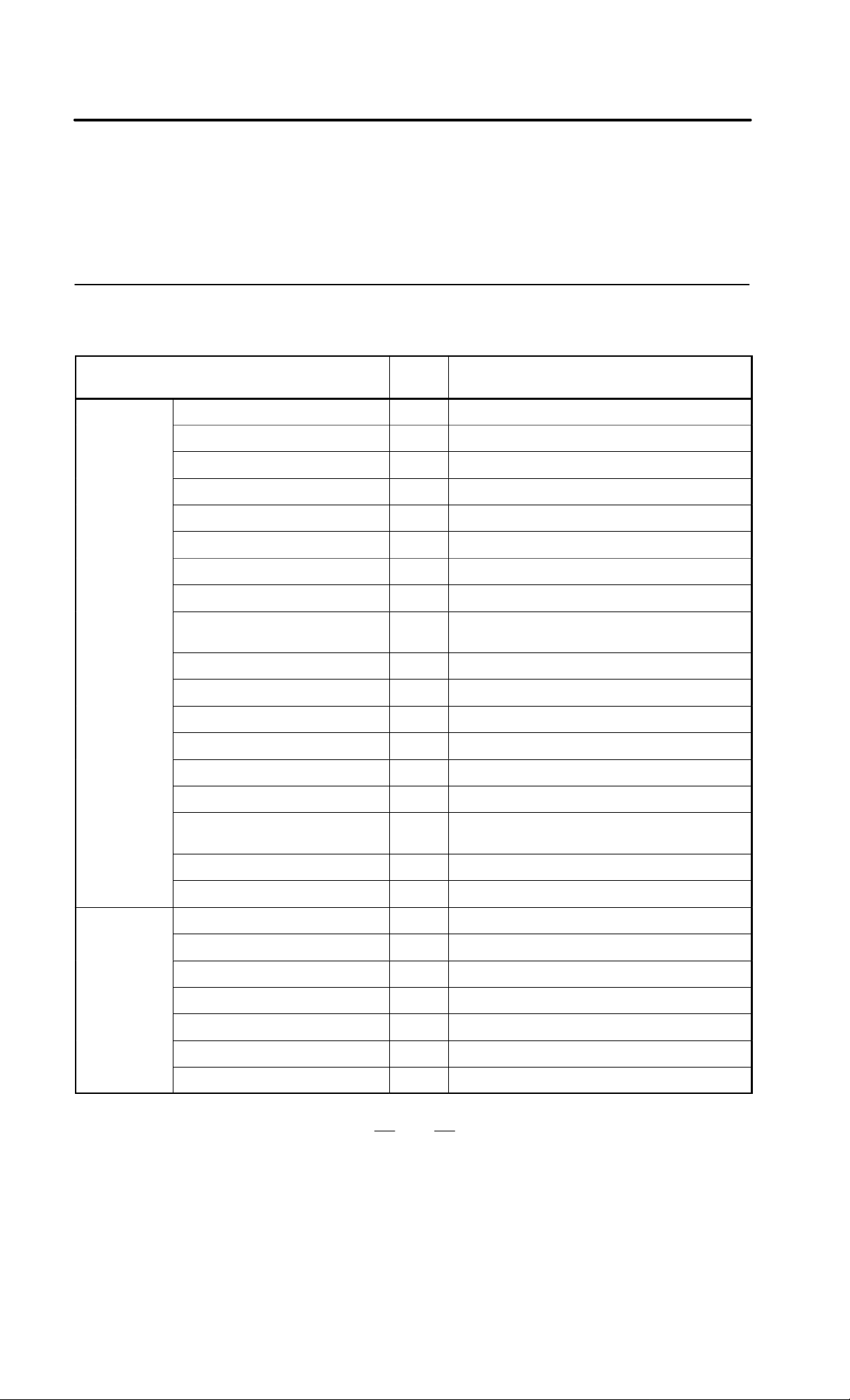
Control unit
Name
Basic unit (4 slots) 60W Power supply AI
Basic unit (4 slots) 80W Power supply BI
Basic unit (6 slots) 80W Power supply BI
Basic unit (8 slots) 80W Power supply BI
Main CPU board 20W
PMC board 18W
Sub board 18W
Option 1 board 15W
RISC Board 18W Cannot be used on
Buffer board (Multiple axis) 6W
AXES CPU (Multiple axis) 15W
MMC–II CPU board 20W Can be used only on series 150–B
MMC–II Graphic board 20W Can be used only on series 150–B
Heat
loss
Remarks
15TED/15TEE/15TEF/15MEK/15MEL
CRT/MDI
MMC–III CPU board 20W Can be used only on series 150–B
MMC–IV CPU board 15W Can be used only on series 150–B
OSI/Ethernet board 18W Cannot be used on
15TED/15TEE/15TEF/15MEK/15MEL
Data server board 18W
HSSB interface board 3W Can be used only on series 150–B
9″ monochrome CRT/MDI 14W For both small and standard type
9″ color CRT/MDI 38W For both small and standard type
9″ monochrome PDP/MDI 20W For both small and standard type
10.4″ color LCD/MDI 20W For both graphic function built–in type and MMC–IV
9.5″ color LCD/MDI 20W
14″ color CRT/MDI 70W
9.5″ LCD (monochrome STN) 10W
14
Page 22
B–62073E/04
A
B
3. INSTALLATION
Connection unit
Operator’s
panel
I/O unit
model
I/O unit
model
Name Remarks
Connection unit 1 35W
Connection unit 1+2 60W
Operator’s panel connection unit 30W
AIF01A, AIF01B 1.2W
AID32A, AID32B 1.2W) 0.23W number of ON points
AID16A, AID16B 0.1W) 0.21W number of ON points
AID32E, AID32F 0.1W) 0.23W number of ON points
BIF04A1 1.6W
AIF02C 1.2W
BID16A1, BID16B1 1.5W) 0.23 number of ON input points
BID16P1, BID16Q1 0.6W) 0.23 number of ON input points
BOA12A1 0.9W) (0.09 1.1 IL2) number of ON output points
BOD16A1 1.0W) (0.13+0.3 IL2) number of ON output points
Heat
loss
BOD16P1 0.3W) (0.13+0.3 IL2) number of ON output points
BIA16P1 0.1W) 0.21 number of ON input points
BMD88A1, BMD88B1 1.3W) 0.23 number of ON input points)
(0.13) 0.3 IL
IL: load current
of output
MMC–II
Multi–tap transformer 51W
BMD88P1, BMD88Q1 0.4W) 0.23 number of ON input points)
(0.13) 0.3 IL
Hard disk unit 26W
Panel mount type 3.5″ floppy disk
unit
Portable type 3.5″ floppy disk unit 12W
Portable type 5.25″ floppy disk unit 26W
Full–key board unit 2W
Extention adapter unit 7W
Portable cassette streamer unit 24W
3W
See FANUC SERVO AMPLIFIER α series DESCRIPTIONS
(B–65162E) for heat loss of servo amplifier.
2
) number of ON output points
2
) number of ON output points
15
Page 23
3. INSTALLATION
B–62073E/04
3.5
INSTALLING THE
HEA T EXCHANGER
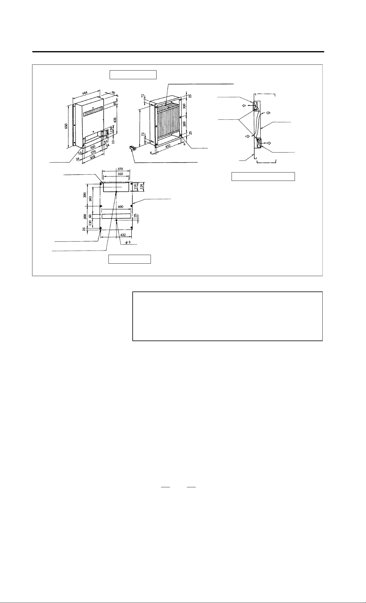
3.5.1
Cooling Fin A/B/C
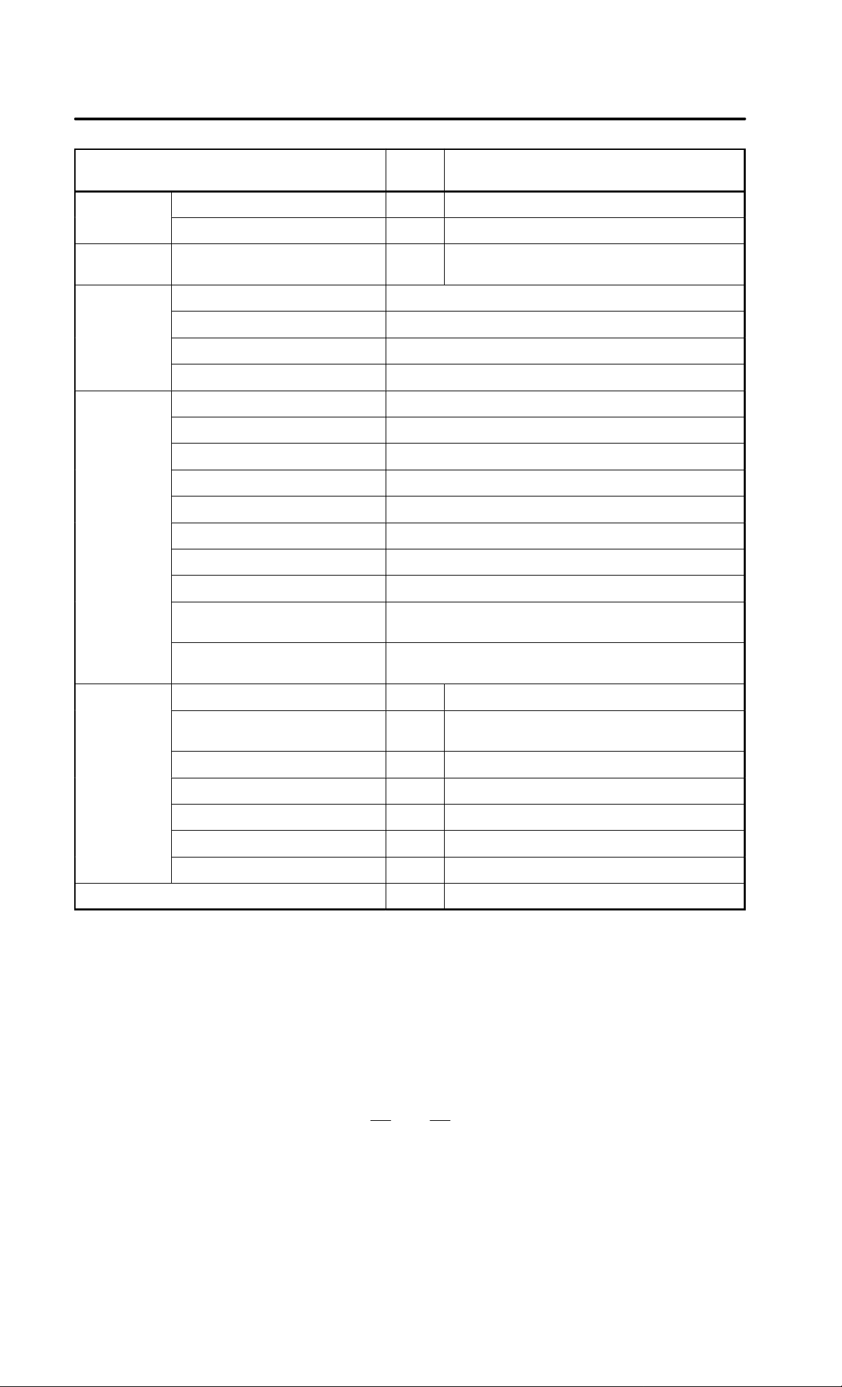
Table 3.5 lists the heat exchangers.
Cooling fins A, B and C are not provided with a fan. Note that a fan motor
is required for any of these cooling fins when it is used as a heat exchanger .
T able 3.5 List of heat exchangers
Name
Cooling fin A A02B–0053–K303 9.1 W/°C 196 90 1000 mm
Cooling fin B A02B–0053–K304 10.1 W/°C 444 90 650 mm
Cooling fin C A02B–0053–K305 25.2 W/°C 560 90 970 mm
Heat exchanger for
CRT/MDI unit
Heat pipe type heat
exchanger
Ordering
specification
A02B–0060–K401 5.0 W/°C 390 86 480 mm
A02B–0094–C901 9.0 W/°C 226 132 415 mm
Cooling
capacity
Size
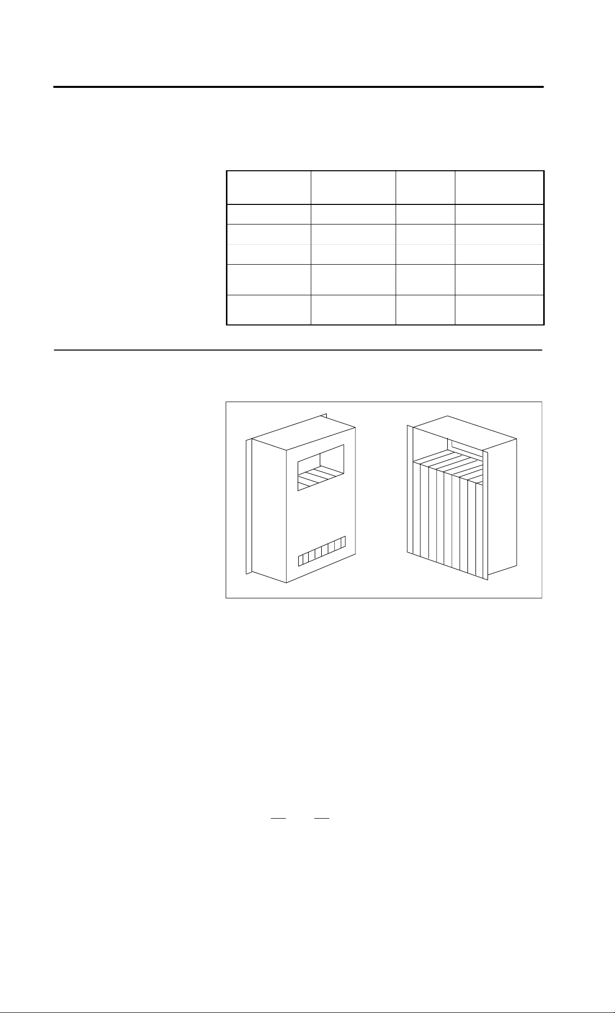
The cooling fin is shown below (Fig. 3.5.1 (a)). It is installed in a cabinet
made by the machine tool builder.
Viewed from cabinet mounting side
Fig. 3.5.1 (a) External view of cooling fin
16
Page 24
B–62073E/04
3. INSTALLATION
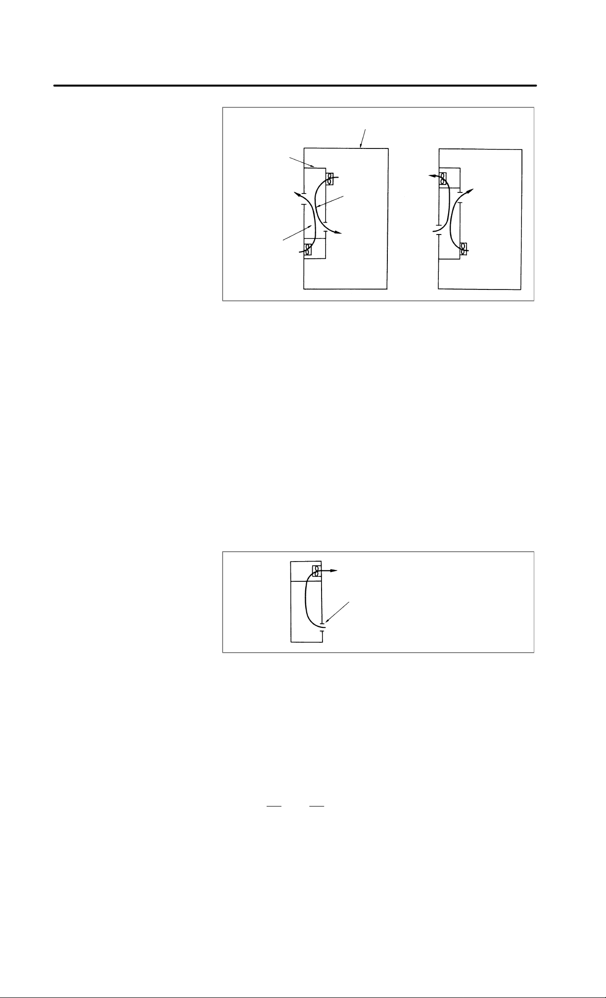
Cabinet
Cooling fin
Inside air
flow
Outside air
flow
Fig. 3.5.1 (b) Internal view of cooling fin
The cooling fin can be installed in two ways, as shown in Fig. 3.5.1 (b).
The following lists the general precautions to be observed when using the
cooling fins :
1) The fans are not included with the cooling fin. They should be
provided by the machine tool builder.
2) Bring in the outside air from the bottom and exhaust the hot air from
the top.
3) The inside air may flow from top to bottom or bottom to top. However ,
generally decide the direction as follows :
a) Bring in the air near high heat loss components.
b) Exhaust the air toward the most important components to be
cooled.
4) For the cooling fin to display the specified cooling capacity, the air
inside the cooling fins must flow at a velocity of 2.5 m/sec or greater.
(velocity of air flow measurement)
Set the slit to the intake side and
measure the velocity at the slit.
5) Generally , install the cooling fins to the door . But be sure that the door
does not bend when installing the cooling fin. The cooling fins are
equipped with packing.
17
Page 25
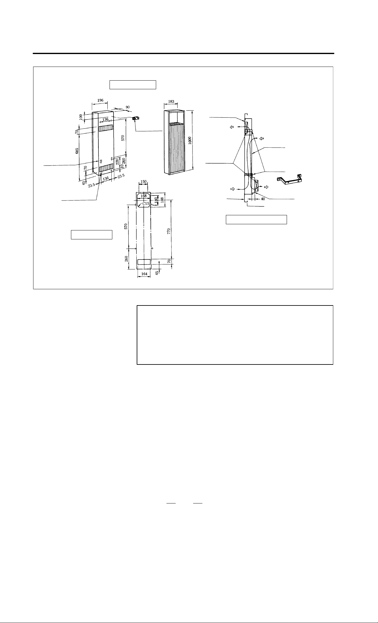
3. INSTALLATION
Mounting metals
for cooling fins
4–M4
Mounting screw
External dimensions
T erminal
block for fan
motor G–04
(Attached to
the cooling fins.
Its height is 20
mm)
Fan mounting
plate
Fan motor
Cooling fins
Mounting metal
for cooling fins
B–62073E/04
4–M4
Mounting screw
for fan mounting plate
Panel cut drawing
Door
Mounting diagram (example)
Fig. 3.5.1 (c) External dimension mounting method of cooling fin A (A02B–0053–K303)
NOTE
1 Fan motor, mounting plate for fan motor and mounting metal
for cooling fins are not attached to the cooling fins.
So, prepare them at the machine tool builder.
2 Use two fan motors with about 50 W power.
3 Weight: 6.5 kg
Mounting plate
for fan motor
Mounting metal
for cooling fins
(sheet metal
about 3 mm
thick).
18
Page 26
B–62073E/04
External dimensions
Mounting stud for cooling fins
(2 studs are attached top and bottom)
Mounting
hole for fan
motor
3. INSTALLATION
Mounting hole
for fan motor
4–M4
(Mounting hole
for fan motor)
6–6 dia hole or
M5 stud bolt
Stud hole
(Make a hole 5 dia
for fan motor)
4–M4
T erminal block for fan motor G–04
Hole
Hole
Panel cut drawing
(Attached to the cooling fins.
Its height is 20 mm)
External shape of
cooling fins.
6–6 dia.
Mounting hole
Fan motor
Door
Mounting diagram (example)
Cooling fins
Fig. 3.5.1 (d) External dimension mounting method of cooling fin B (A02B–0053–K304)
Mounting
plate for fan
motor
NOTE
1 Fan motor and mounting plate are not attached to the
cooling fins. So, prepare them, at the machine tool builder.
2 Use four fan motors with about 20 W power.
3 Weight: 7.5 kg
19
Page 27

3. INSTALLATION
B–62073E/04
6–M4
Mounting hole
for fan motor
6–6 dia hole or
M5 stud bolt
5–M4
(Mounting hole
for fan motor)
External dimensions
Terminal block
for fan motor
G–04
(Attached to
the cooling
fins.Its height
is 20 mm)
(This hole combines mounting
hole and stud
hole.)
Mounting stud for cooling fins
(Attached to the cooling fins)
8–6 dia.
Mounting hole
External shape
of cooling fins.
Mounting plate
for fan motor
Fan motor
Door
Cooling fins
Mounting diagram (example)
Mounting
plate for fan
motor
Panel cut diagram
Fig. 3.5.1 (e) External dimension and mounting method of cooling fin C (A02B–0053–K305)
NOTE
1 Fan motor and mounting plate for fan motor are not
attached to the cooling fins. Prepare them at the machine
tool builder.
2 Use two fan motors with about 40 W power.
3 Weight: 13.5 kg
20
Page 28
B–62073E/04
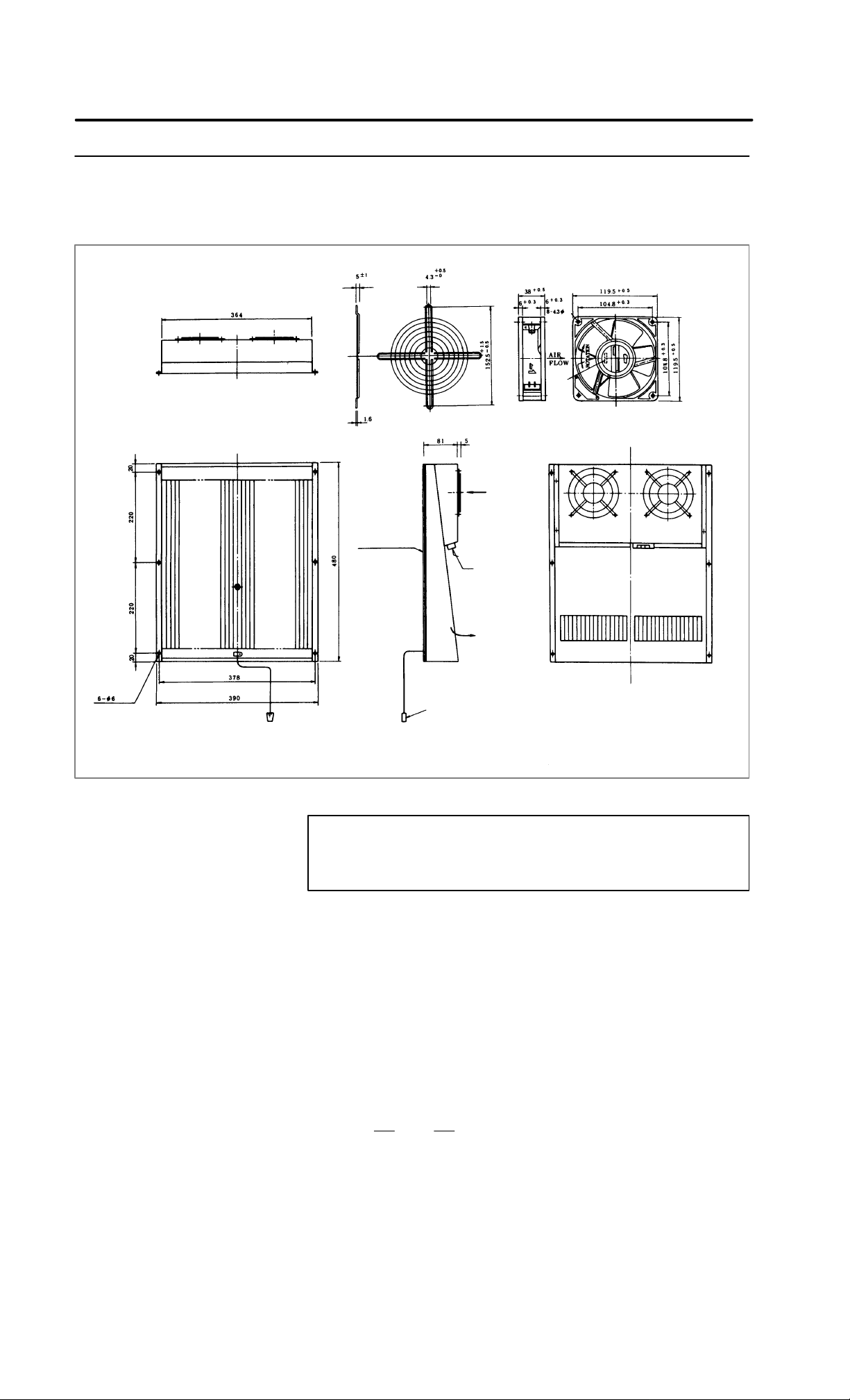
3.5.2
Heat Exchanger for
CRT/MDI Unit
External Dimensions of
Finger Guard
Air inlet
3. INSTALLATION
hole
Lot
No.
External Dimensions of External
Cooling Fan
Weight: 0.65 kg
Packing
Power terminal
M4 screw
AC200 V 50 Hz
AC200 V/220 V
60 Hz
48 W
Air outlet
Cooling fin: About 6 kg
Connector for external
cooling fan
(Excluding attached parts)
Fig. 3.5.2 (a) External dimensions of external cooling fan and cooling unit for CRT/MDI (A02B–0060–K401)
NOTE
External cooling fan and finger guard are attached beside
cooling fin.
21
Page 29
3. INSTALLATION
Heat exchanger
Air outlet
Air outlet
(1)
Air inlet
InsideOutside
Prepare mounting
screws and mounting panel.
External cooling fan (attached)
Finger guard (attached)
B–62073E/04
Main body
of heat
exchanger
(1)Use M5 screws to mount the heat exchanger.
(2)Be careful with air flow when securing the external cooling fan.
(3)Prepare a mounting panel for external cooling fan and install
the panel where it can be exchanged externally.
(4)Drill mounting holes for external cooling fan and air outlet
on heat exchanger mounting panel.
Fig. 3.5.2 (b) Mounting methods of heat exchanger for CRT/MDI
22
Page 30
B–62073E/04
3. INSTALLATION
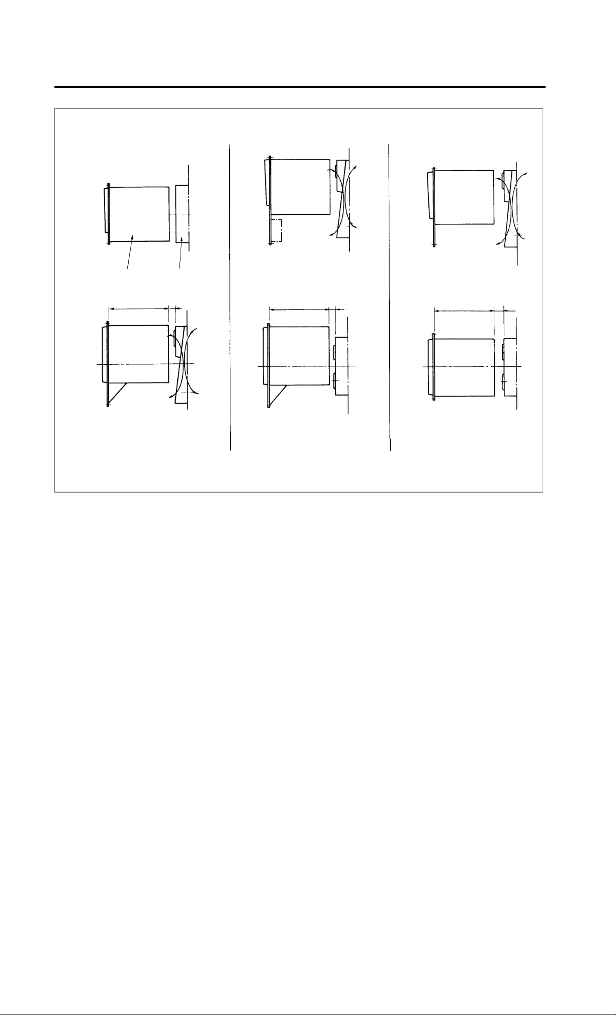
Side view
T op view
Horizontal type CRT/MDI only
Inside Outside
CRT/MDI Heat exchanger
Min
370
35
Horizontal type CRT/MDI
and machine operator’s panel
Min
370
35
Vertical type CR T/MDI only
Min
370
35
Refer to these figures for allocation of CRT/MDI and heat exchanger.
Fig. 3.5.2 (c) Allocation of 14″ color CRT/MDI and heat exchanger
23
Page 31

3. INSTALLATION
3.5.3
The Heat Pipe Type
Heat Exchanger
B–62073E/04
3.5.3.1
Installation
The heat pipe type heat exchanger is used for cooling the airtight cabinet
of small sized electronic devices. It is a compact, lightweight, and
heat–efficient unit. Because the fan is built–in, it is used simply by
installing it, performing the “panel cut” operation.
(1)Specifications
Installation format Installation type in board
Fan
specifications
D
Order specifications Heat exchanger A02B–0094–C901
Cooling ability
(W/°C)
Voltage (V) 200 VAC
Frequency (Hz) 50 60
Rating current (A) 0.28 0.24
Rating input (W) 28 26
Weight (kg) 4
Color Munsell signal N1.5
9 (50 Hz when operating)
Remarks
D
A filter is installed on the outside air inhalation side.
D
The installation board thickness is the standard 1.6 t.
D
When a fan motor and filter are necessary for maintenance, prepare
them separately.
Fan motor specifications A90L–0001–0219#A
Filter specifications A250–0689–X004
D
If the heat exchanger is installed near the CRT, screen distortion may
occur due to magnetic flux leakage from the fan motor.
24
Page 32

B–62073E/04
3. INSTALLATION
(2)External dimensions
Power source
terminal M4
Earth terminal
M4
Internal fan unit
AIR FLOW
AIR FLOW
External fan unit
(Installation board thickness)
Fig. 3.5.3.1 (a) External dimensions diagram of heat pipe type heat transformer
25
Page 33

3. INSTALLATION
B–62073E/04
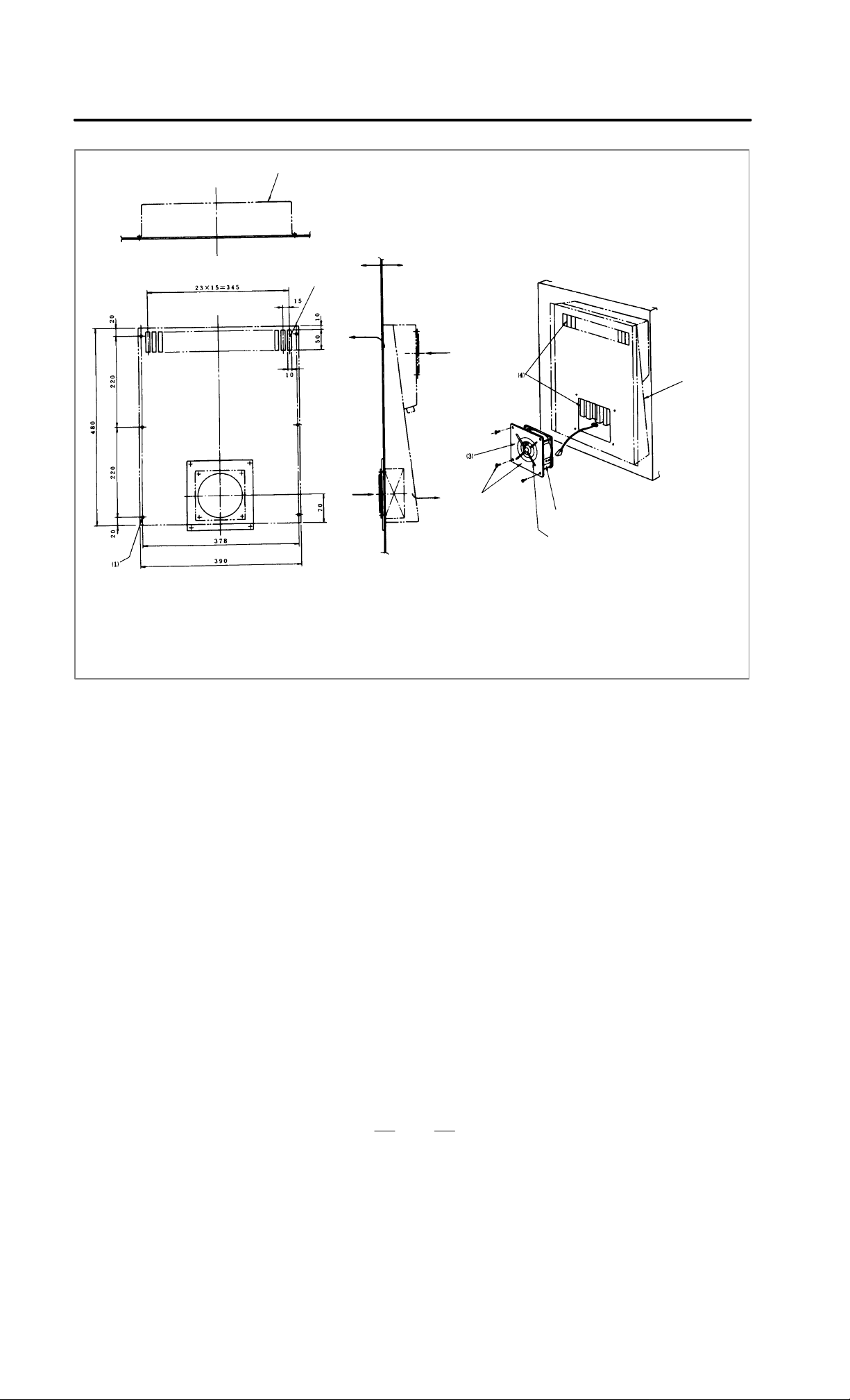
(3)Panel cut dimensions
180
2.5
190190
HOLE
3–f 5
187.5
175
6–f 6 or stud welder (M4)
214
Fig. 3.5.3.1 (b) External dimensions diagram of panel cut
(4)Installation method
Please install the heater exchanger by the following sequence:
Heat exchanger
main unit
Installation screw B (1)
Fan power cable
(detach the connector)
External fan unit
Earth cable
(if the installation screw on the fan side is
detached, it can be taken out.)
Installation screws A (2)
Installation screw
Installation panel
Installation screw B (1)
(Fixed to the panel)
(Fig. 1) (Fig. 2)
26
Page 34

B–62073E/04
3. INSTALLATION
(a)Take out the external fan unit from the heat exchanger main unit.
(Fig. 1)
Detach the external fan unit installation screws A (2 pieces), take
out the unit from the main unit by sliding it down, and detach the
earth cable and the power cable to the fan. Also detach the
installation screw B (1 piece).
(b) Install the heat exchanger main unit in the installation section
which has been panel cut. (Fig. 2)
When fastening down the heat exchanger main unit with the
screws, first, temporarily secure the panel and the heat exchanger
main unit with the installation screw B, which was taken out in 1).
After that, secure the main unit by the installation screws. In this
case, the external fan unit installation screw holes should be
aligned with the main unit screw holes. (Please provide the
installation screws for the heat exchanger main unit.)
Because this product is composed of plastic, set the value shown
below for the screw tightening torque.
Heat exchanger main unit (M4 screw): 11 kgf.cm
External fan unit (M3 screw): 5 kgf.cm
(c)Connect the power cable and the earth cable to the external fan unit
(the unit detached in section 1), and secure the installation screw
A to the main unit from the outside.
The installation is now complete.
3.5.3.2
Maintenance
It is necessary to regularly clean the heat pipe type heat exchanger,
because the cooling ability is reduced by the accumulation of dust. The
frequency of the cleaning needed differs according to the installation
environment and therefore should be determined by your own judgment
regarding the amount of dirt.
(1)Air filter cleaning and replacement method
(a)When cleaning and replacing the filter, be sure to cut off the fan’s
electric power source.
(b)Detach the filter cover and take out the filter inside.
Detach the cover by pressing the flanges
which are in the grooves of both sides towards the inside using a flat blade screwdriver, etc.
27
Page 35

3. INSTALLATION
B–62073E/04
(c)Protect the filter from silting due to dust by blowing air on both
sides.
(d)When dirt is conspicuous, press wash with a neutral detergent, rinse
with clean water, and allow to dry naturally. When replacing,
replace with the same product.
(e) To install, insert the filter in the cover, align the flange in the
groove, and press. Confirm that the cover will not come loose even
if it is pulled.
(2)Cleaning heat exchanger
(a)When cleaning, be sure to cut off the fan power source.
(b)Take out the external fan unit from the heat exchanger main unit.
Detach the two installation
Heat exchanger
main unit
Installation screws B (1)
Power cable for fan
(detach the connector)
Earth cable (if the installation screw on the
fan side is detached, it can be taken out)
screws (A) of the external fan
unit, and detach the unit from
the main unit by sliding it
down. Detach the power
source cable to the fan and
the earth cable. Also detach
installation screws (B).
External fan unit
Installation screws A (2)
(i) Cleaning fan unit
Wipe the dirt, condensation, etc., which has accumulated on the fan
motor and fan installation case with a dry cloth. When the
condensation, etc. has accumulated and the dirt is difficult to
remove, soak a cloth in neutral detergent, lightly squeeze it and
wipe away the dirt.
However , take care not to allow the detergent to enter the electrical
sections such as the internal rotor of the fan motor.
28
Page 36

B–62073E/04
3. INSTALLATION
(ii)Cleaning heat exchanger fan
Detach the heat exchanger from the unit and either blow off with
air, wipe off with a dry cloth, or brush the accumulated dirt,
condensation, etc.
When the dirt is especially severe
(1) Detach the internal fan unit, the terminal unit, and the cable
from the main unit.
Main unit
T erminal unit and cable
(2)Using a neutral detergent, remove the dirt from the main unit fan
section by brushing.
At this time, take care not to bend the fin of the element.
(3)After cleaning, dry well.
(iii)Installation
After completing cleaning of the fan unit and heat transformer.
(1)Install the terminal unit and cable in the original position.
(2)Install the fan unit in the original position. At this time, do not
forget to connect the fan power cable and the earth cable.
29
Page 37

3. INSTALLATION
solenoid and relay
electromagnetic shield
B–62073E/04
3.6
ACTION AGAINST NOISE
3.6.1
Separating Signal Lines
The CNC has been steadily reduced in size using surface–mount and
custom LSI technologies for electronic components. The CNC also is
designed to be protected from external noise. However, it is difficult to
measure the level and frequency of noise quantitatively, and noise has
many uncertain factors. It is important to prevent both noise from being
generated and generated noise from being introduced into the CNC. This
precaution improves the stability of the CNC machine tool system.
The CNC component units are often installed close to the parts generating
noise in the power magnetics cabinet. Possible noise sources into the
CNC are capacitive coupling, electromagnetic induction, and ground
loops.
When designing the power magnetics cabinet, guard against noise in the
machine as described in Subsections 3.6.1 to 3.6.5.
The cables used for the CNC machine tool are classified as listed in the
following table:
Bind the cables in each group as described in the action column.
Group Signal line Action
A
Primary AC power line
Secondary AC power line
AC/DC power lines (containing
the power lines for the servo
and spindle motors)
AC/DC solenoid
Bind the cables in group A
p
separately (Note 1) from groups
B and C or cover group A with
an electromagnetic shield (Note
2).
See Section 3.6.4 and connect
spark killers or diodes with the
solenoid and relay.
p
AC/DC relay
B
DC solenoid (24 VDC)
DC relay (24 VDC)
DI/DO cable between the CNC
and power magnetics cabinet
DI/DO cable between the CNC
and machine
Connect diodes with DC
.
Bind the cables in group B
separately from group A or
cover group B with an
.
Separate group B as far from
Group C as possible.
It is more desirable to cover
group B with the shield.
30
Page 38

B–62073E/04
ith
g
3. INSTALLATION
Group ActionSignal line
C
Cable between the CNC and
servo amplifier
Cable for position and velocity
feedback
Cable between the CNC and
spindle amplifier
Cable for the position coder
Cable for the manual pulse
generator
Cable between the CRT and
MDI
RS232C and RS422 interface
cables
Cable for the battery
Other cables to be covered with
the shield
Bind the cables in group C
separately from group A or
cover group C w
electromagnetic shield.
Separate group C as far from
Group B as possible.
Be sure to perform shield
processing in Section 3.6.5.
p
an
NOTE
1 The groups must be 10 cm or more apart from one another
when binding the cables in each group.
2 The electromagnetic shield refers to shielding between
groups with grounded steel plates.
3.6.2
Ground
The following ground systems are provided for the CNC machine tool:
(1)Signal ground system (SG)
The signal ground (SG) supplies the reference voltage (0 V) of the
electrical signal system to the machine.
(2)Frame ground system (FG)
The frame ground system (FG) is used for safety, and suppressing
external and internal noises. In the frame ground system, the frames
and cases of the units, panels, and shields for the interface cables
between the units are connected.
(3)System ground system
The system ground system is used to connect the frame ground
systems connected between devices or units with the ground.
31
Page 39

3. INSTALLATION
Power
magnetics
unit
Power
magnetics
cabinet
Servo
amplifier
Distribution board
CNC
control unit
B–62073E/04
Signal ground system
Frame ground system
System ground system
Machine toolOperator’ s panel
W ARNING
Notes on connecting the ground systems
D
Connect the signal ground with the frame ground (FG) at
only one place in the CNC control unit.
D
The grounding resistance of the system ground shall be 100
ohms or less (class 3 grounding).
D
The system ground cable must have enough
cross–sectional area to safely carry the accidental current
flow into the system ground when an accident such as a
short circuit occurs.
(Generally, it must have the cross–sectional area of the AC
power cable or more.)
D
Use the cable containing the AC power wire and the system
ground wire so that power is supplied with the ground wire
connected.
32
Page 40

B–62073E/04
3. INSTALLATION
3.6.3
Grounding Each Unit
(a)Control unit
Control unit
Signal
ground (SG)
M4
(Only thread
hole)
M3
(With thread)
Ground cable
Wire with a sectional
area 2 mm2 or more
PCB
SG
M3
Ground cable
Ground plate of
the cabinet
System ground
Connect the 0 V line of the electronic circuit in the control unit with the
ground plate of the cabinet via the signal ground (SG) terminal.
33
Page 41

3. INSTALLATION
B–62073E/04
(b)CRT unit
(c)Connection unit 1/2
(Rear side)
14″CRT
(Rear side)
M5 stud
f
M4 stud
f
9″ PDP
9″ CRT
9.5″ LCD
10.4″ LCD
(d)Operator’s panel connection unit
f
×
M4 screw
Ground install board
f
×
34
Page 42

B–62073E/04
3. INSTALLATION
(e)Tape raeder unit
M4 terminal
for ground
(Rear side)
M5 stud
(Rear side)
f
T ape reader with reel T ape reader without reel
(f) I/O Unit model A
Ground the terminals for (ABU05A, ABU05B, ABU10A, ABU10B)
ABU05A, ABU10A ABU05B, ABU10B
M5 stud
f
M3 terminal
for ground (SG)
M4 mount hole
for ground
NOTE
Ground SG terminal to the mount hole.
35
Page 43

3. INSTALLATION
B–62073E/04
3.6.4
Noise Suppressor
The AC/DC solenoid and relay are used in the power magnetics cabinet.
A high pulse voltage is caused by coil inductance when these devices are
turned on or off.
This pulse voltage induced through the cable causes the electronic circuits
to be disturbed.
T o reduce the pulse voltage, use a spark killer for an AC device or a diode
for a DC device.
Notes on selecting the spark killer
D
Use a spark killer consisting of a resistor and capacitor in series. This
type of spark killer is called a CR spark killer.
(A varistor is useful in clamping the peak voltage of the pulse voltage,
but cannot suppress the sudden rise of the pulse voltage. FANUC
therefore recommends a CR spark killer.)
D
The reference capacitance and resistance of the spark killer shall
conform to the following based on the current (I (A)) and DC
resistance of the stationary coil:
1) Resistance (R): Equivalent to DC resistance of the coil
2
2) Capacitance (C):
1
10
2
1
to
(mF)
20
Equivalent circuit of thespark killer
AC relay
Spark killer
CR
Spark killer
Motor
36
Page 44

B–62073E/04
3. INSTALLATION
3.6.5
Cable Clamp and Shield Processing
The CNC cables that require shielding should be clamped by the method
shown below. This cable clamp treatment is for both cable support and
proper grounding of the shield. To insure stable CNC system operation,
follow this cable clamp method.
Partially peel out the sheath and expose the shield. Push and clamp by
the plate metal fittings for clamp at the part. Metal fittings for clamp are
attached to the control unit. The ground plate must be made by the
machine tool builder, and set as follows :
Ground plate
Cable
Metal fittings for clamp
40 mm to 80 mm
Fig. 3.6.5 (a) Cable clamp (1)
37
Page 45

3. INSTALLATION
B–62073E/04
Machine side
installation
board
Control Rack
Ground plate
Metal fittings
for clamp
Shield cover
Fig. 3.6.5 (b) Cable clamp (2)
Prepare ground plate like the following figure.
Ground terminal
(grounded)
Hole for securing metal fitting clamp
Mount screw hole
Fig. 3.6.5 (c) Ground plate
For the ground plate, use a metal plate of 2 mm or thicker, which surface
is plated with nickel.
38
Page 46

B–62073E/04
3. INSTALLATION
8mm
12mm
20mm
Fig. 3.6.5 (d) Ground plate holes Ground plate
(Reference) Outer drawings of metal fittings for clamp.
Max. 55mm
Ground plate
28mm
6mm
17mm
Fig. 3.6.5 (e) Outer drawings of metal fittings for clamp
Ordering specification for metal fittings for clamp
A02B–0118–K001 (5 pieces)
NOTE
Select cables of appropriate length.
We do not recommend using cables longer than necessary .
Such cables may demonstrate poor resistance to electrical
noise or be influenced by electrical noise. Also, if excess
cable is wrapped up in a coil, this may increase impedance.
This may induce an extremely high voltage during ON/OFF
switching of signals, or lead to erroneous operation caused
by malfunction or electrical noise.
39
Page 47

3. INSTALLATION
Ã
Ã
Ã
Ã
Ã
Ã
Ã
Ã
3.7
CONTROL UNIT
B–62073E/04
3.7.1
Configuration and
Installation of the
Control Unit
Option board
ÃÃ
Optionboard
ÃÃ
Printed circuit boards used for control of Series 15–B is mounted in a rack
equipped with several slots.
Option board
ÃÃ
Option board
RISC
MMC–II
MMC–II
Graphic
MMC–III
MMC–IV
OSI ethernet
OPTION BASIC
Option 1
board
ÃÃ
Graphic display control
Communication control
(Remote
buffer)
(DNC 1)
F–BUS
Sub board
ÃÃ
SUB CPU
4–axis control
spindle ( 2)
Analog I/O
HDI 4
RS232C
RS422
Main CPU
board
ÃÃ
CNC CPU
4–axis control
spindle ( 2)
CRT/MDI
RS232C 2
HDI 4
MPG 3
PMC board
ÃÃ
PMC CPU
I/O LINK
Memory Card
Conversion
control
Power supply
unit
ÃÃ
ON/OFF
control
Power
supply unit
AI or BI
MAIN
CPU
PSUPMC MAIN
CPU
PSUPMC MAIN
CPU
PSUPMC MAIN
CPU
Fig. 3.7.1 (a) Control unit configuration of Series 15–B
NOTE
The SUB CPU, RISC, MMC and OSI/Ethernet boards cannot be used on the
15TED/15TEE/15TEF/15MEK/15MEL.
40
PSUPMC
Page 48

B–62073E/04
Ã
Ã
Ã
Ã
Ã
Ã
Ã
3. INSTALLATION
Option board Option board Option board Option 1
ÃÃÃÃÃ
ÃÃ
Option board
RISC
MMC–II
MMC–II
Graphic
MMC–III
MMC–IV
OSI ethernet
board
ÃÃ
Graphic display
control
Communication control
(Remote buffer)
(DNC 1)
F–BUS
OPTION BASIC
Sub CPU
board
ÃÃ
SUB CPU
Analog input
HDI 4
RS232C
RS422
Main CPU
board
ÃÃ
CNC CPU
CRT/MDI
RS232Cx2
HDIx4
MPGx3
PMC board Power supply
ÃÃ
PMC CPU
I/O LINK
Memory Card
Conversion
control
unit
ÃÃ
ON/OFF
control
Power
supply unit
AI or BI
CPU
MAIN
CPU
PSUPMC MAIN
SUB
CPU
CPU
PSUPMC MAIN
SUB
CPU
CPU
PSUPMCSUB
Fig. 3.7.1 (b) Control unit configuration of Series 15–B (Multiple axis)
NOTE
The SUB CPU, RISC, MMC and OSI/Ethernet boards cannot be used on the
15TED/15TEE/15TEF/15MEK/15MEL.
41
Page 49

3. INSTALLATION
Ã
Ã
Ã
Ã
B–62073E/04
AXES CPU
board
ÃÃ
AXES CPU
4–axis control
spindle ( 2)
Near zero
MPG 3
Buffer board
ÃÃ
Buffer
AXES CPU
board
ÃÃ
AXES CPU
4–axis control
spindle ( 2)
Near zero
OPTION BASIC
Power
supplyy unit
ÃÃ
ON/OFF
control
Power
supply unit
AI or BI
BUF
FER
CPU
PSUAXES
BUF
FER
CPU
PSUAXES
BUF
FER
CPU
PSUAXES
Fig. 3.7.1 (c) Configuration of Series 15–B additional locker used with multiaxis machines
NOTE
More than one axis CPU board may be used, depending on
the system configuration.
The rack consists of a plastic box, fan motors and a backplane PCB. Since
the rack is provided with built–in fan motors, it does not require the
external air flow conditions described in Section 3.5. The air comes into
the rack from the bottom and goes out through the fan motor, which is
located on the top of the rack. Space as shown in Fig. 3.7.1 (d) must be
reserved not to disturb the air flow ((A), (B))
The backplane PCB, which is located on the rear side of the rack,
interconnects the PCBs installed in the rack. It has another connector
which appears at the left side panel of the rack. The connector may be used
in the future. The space (C) for this shall be reserved as shown in Fig.
3.7.1 (d).
42
Page 50

B–62073E/04
3. INSTALLATION
250
30
AIR FLOW AIR FLOW
50
50
unit [mm]
Fig. 3.7.1 (d)
172
43
Page 51

3. INSTALLATION
Ã
3.7.2
Battery for Memory
Backup
B–62073E/04
W ARNING
ÃÃÃÃ
The part program, offset data and system parameters are stored in the
CMOS memory of the control unit and they are retained even while the
main power is cut off. The power of the memory is backed up by a lithium
battery which is mounted on the front panel of the power supply unit. Data
is retained even while the main power is OFF . The control unit is shipped
from the factory equipped with the battery.
Replace the battery within one week after the “BAT” warning message is
displayed blinking on the CRT screen indicating lower battery power , or
when the battery alarm signal is output to the PMC. Otherwise, data in
memory will be lost.
A lithium battery is used for the battery. Follow the following
precautions.
WARNING
Incorrect replacement of the battery may cause an
explosion.
Replace only with the specified battery.
Power Supply
Unit front panel
Battery
Compartment
Battery inside
Fig. 3.7.2
NOTE
The part program, parameters and variables are stored to
non–volatile memory in the CNC unit. Normally, turning the
power ON and OFF will not cause data in memory to be lost.
However, it is conceivable that erroneous operation may
delete data, or important data stored in non–volatile may
have to be deleted to restore trouble.
We recommend backing up data beforehand so that the
system can be restored quickly in the event that unexpected
trouble occurs.
44
Page 52

B–62073E/04
Ã
3.7.3
Replacing the Battery
3. INSTALLATION
W ARNING
ÃÃÃÃ
Before you replace the battery , turn the machine tool (CNC) ON and make
an emergency stop.
Replacing the battery involves opening the cabinet with the power still
ON. So, only personnel trained in maintenance and safety procedures may
replace batteries.
When you open the cabinet to replace the battery, do not touch
high–voltage circuits indicated by the
mark and covered with
anti–electric shock covers.
If the cover becomes loose and you touch a high–voltage circuit, you will
be electrocuted.
(1)Use a lithium battery.
When using battery unit A02B–0162–H101 or –H102
Ordering drawing number: A02B–0120–K106
When using battery unit A02B–0162–H107 or –H108
Ordering drawing number: A02B–0200–K102
(2)Turn on the 15–B.
(3)Remove the battery case from the front panel of the power supply unit.
The case can be removed easily by holding the top and bottom of it and
pulling.
Front panel of the
power supply unit
Battery
Battery case
Fig. 3.7.3 (a) Replacing the battery (1)
45
Page 53

3. INSTALLATION
B–62073E/04
(4)Remove the connector from the battery.
BATTERY
Cable connector
PC board
connector
Battery
Front panel of hte
power supply unit
Fig. 3.7.3 (b) Replacing the battery (2)
(5)Replace the battery and reconnect the connector.
(6)Install the battery case.
(7)Turn off the Series 15–B.
46
Page 54

B–62073E/04
3.8
CABLE LEAD–IN
DIAGRAM
3.8.1
Configuration of Control Unit Connectors
3. INSTALLATION
unit [mm]
Power supply
unit
Fig. 3.8.1 (a)
(1)Above diagram shows the grid of connector location.
Control board may not have all connectors as shown above.
For actual connector layout of each board, please see the connector
layout diagrams in Fig. 3.8.1 (c) – (s).
47
Page 55

3. INSTALLATION
B–62073E/04
(2)For the power supply unit, please see Fig. 3.8.1 (b–1) and (b–2).
Minislot
unit [mm]
Fig. 3.8.1 (b–1) Power unit connector layout
For power unit A02B–0162–H101 and –H102
48
Page 56

B–62073E/04
3. INSTALLATION
Fig. 3.8.1 (b–2) Power unit connector layout
For power unit A02B–0162–H107 and –H108
49
unit [mm]
Page 57

3. INSTALLATION
B–62073E/04
POS.
FUNCTION
UPPER LINE
MARKING
LOWER LINE
MARKING
LED INDICA TORS
MEMORY C ARD I/F
SERIAL I/O LINK IOLINK JD1A
Fig. 3.8.1 (c) PMC board
50
Page 58

B–62073E/04
3. INSTALLATION
POS.
FUNCTIONFUNCTION
UPPER LINE
MARKING
LOWER LINE
MARKING
LED INDICA TORS
CRT DISPLAY
MDI
SERIAL PORT 1
SERIAL PORT 2
MPG
HIGH SPEED DI–1
SERIAL SPINDLE 1
(POSITION CODER–1)
SPDL-1 JA7A
ANALOG OUT
APC BATTERY APCBA T J A4A
SERVO AMP 1
SERVO AMP 2
SERVO AMP 3
SERVO AMP 4
PULSE CODER 1
PULSE CODER 2
PULSE CODER 3
PULSE CODER 4
LINEAR SCALE 1
LINEAR SCALE 2
LINEAR SCALE 3
LINEAR SCALE 4
Fig. 3.8.1 (d) Main CPU board
51
Page 59

3. INSTALLATION
B–62073E/04
POS.
FUNCTION
LED INDICA TORS
SERIAL PORT 9
SERIAL PORT 4
HIGH SPEED DI–2
ANALOG INPUT
POSITION CODER–2
ANALOG OUT–2
APC BATTERY
SERVO AMP 5
SERVO AMP 6
SERVO AMP 7
SERVO AMP 8
PULSE CODER 5
PULSE CODER 6
PULSE CODER 7
PULSE CODER 8
LINEAR SCALE 5
LINEAR SCALE 6
LINEAR SCALE 7
LINEAR SCALE 8
UPPER LINE
MARKING
LOWER LINE
MARKING
Fig. 3.8.1 (e) SUB board
52
Page 60

B–62073E/04
3. INSTALLATION
POS.
FUNCTION
LED INDICA TORS
CRT DISPLAY
RS232C PORT3
RS422 PORT1
UPPER LINE
MARKING
LOWER LINE
MARKING
With only
graphic
function
With graphic
function and
communication
function
With only
communication
function
Fig. 3.8.1 (f) Option 1 board
NOTE
The communication function refers to the remote buffer
function or DNC1 function.
53
Page 61

3. INSTALLATION
B–62073E/04
POS.
FUNCTION
LEDs
Hard disk interface
Floppy disk interface
Graphic bus
UPPER LINE
MARKING
LOWER LINE
MARKING
Keyboard interface
RS–422 interface
Centronics interface
RS–232C interface, channel 1
RS–232C interface, channel 2
Fig. 3.8.1 (g) MMC–II CPU board
NOTE
The MMC–II CPU (A02B–0120–J202), which requires
three RS–232C channels, uses JD6 as an RS–232C port.
54
Page 62

B–62073E/04
3. INSTALLATION
POS.
FUNCTION
LEDs
Graphic bus
UPPER LINE
MARKING
LOWER LINE
MARKING
CRT interface
Not used
Fig. 3.8.1 (h) MMC–II graphic board
55
Page 63

3. INSTALLATION
B–62073E/04
POS.
FUNCTION
LEDs
VIDEO output (CNC side)
Video input
Serial port 6
Serial port 7
Serial port 8
UPPER LINE
MARKING
LOWER LINE
MARKING
Fig. 3.8.1 (i) MMC–III CPU board
56
Page 64

B–62073E/04
3. INSTALLATION
POS.
FUNCTION
LEDs
CRT I/F
MDI I/F
Serial bort 1
Serial bort 2
Manual pulse generator I/F
High DI I/F
Battery backup for
board replacement
Multiple axis–Bus
UPPER LINE
MARKING
LOWER LINE
MARKING
Fig. 3.8.1 (j) Multiple main CPU board
57
Page 65

3. INSTALLATION
B–62073E/04
POS.
FUNCTION
LEDs
Serial port 9
Serial port 4
High speed DI I/F
Analog input
UPPER LINE
MARKING
LOWER LINE
MARKING
Fig. 3.8.1 (k) Multiple SUB CPU board
58
Page 66

B–62073E/04
3. INSTALLATION
POS.
FUNCTION
LEDs
Operation check input 1
Operation check input 2
Operation check input 3
Operation check input 4
Near zero input
Serial spindle 2
Analog spindle 2
APC Battery
Servo amplifier 1
Servo amplifier 2
Servo amplifier 3
UPPER LINE
MARKING
LOWER LINE
MARKING
Servo amplifier 4
Pulse coder 1
Pulse coder 2
Pulse coder 3
Pulse coder 4
Linear scale 1
Linear scale 2
Linear scale 3
Linear scale 4
Fig. 3.8.1 (l) AXIS CPU board
59
Page 67

3. INSTALLATION
B–62073E/04
POS.
FUNCTION
LEDs
UPPER LINE
MARKING
LOWER LINE
MARKING
Multiple axis–Bus
Fig. 3.8.1 (m) Multiple buffer board
60
Page 68

B–62073E/04
Ã
Ã
Ã
Ã
Ã
Ã
Ã
Ã
Ã
Ã
Ã
Ã
Ã
Ã
Ã
Ã
Ã
Ã
Ã
Ã
Ã
Ã
Ã
Ã
Ã
Ã
Ã
Ã
Ã
Ã
ÃÃ
Ã
Ã
Ã
ÃÃ
ÃÃ
ÃÃ
ÃÃ
3. INSTALLATION
POS.
10
12
13
14
15
16
17
18
19
20
21
ГГГГГ
ГГГГГ
ГГГГГ
ГГГГГ
1
ГГГГГ
2
ГГГГГ
3
ГГГГГ
4
ГГГГГ
5
ГГГГГ
6
ГГГГГ
7
ГГГГГ
8
ГГГГГ
9
ГГГГГ
ГГГГГ
ГГГГГ
11
ГГГГГ
ГГГГГ
ГГГГГ
ГГГГГ
ГГГГГ
ГГГГГ
ГГГГГ
ГГГГГ
ГГГГГ
ГГГГГ
ГГГГГ
ГГГГГ
ГГГГГ
ГГГГГ
ГГГГГ
Ã
Ã
Ã
FUNCTION
UPPER LINE
MARKING
LOWER LINE
MARKING
LEDs STATUS/ALARM
LEDs LV ALM
Fuse F21 5A
Fig. 3.8.1 (n) RISC board
NOTE
The RISC board cannot be used on the
15TED/15TEE/15TEF/15MEK/15MEL.
61
Page 69

3. INSTALLATION
Ã
Ã
Ã
Ã
Ã
Ã
Ã
Ã
Ã
Ã
Ã
Ã
Ã
Ã
Ã
Ã
Ã
Ã
Ã
Ã
Ã
Ã
Ã
Ã
Ã
Ã
Ã
Ã
Ã
Ã
ÃÃ
B–62073E/04
POS.
ГГГГГГ
ГГГГГГ
ГГГГГГ
ГГГГГГ
1
ГГГГГГ
2
ГГГГГГ
3
ГГГГГГ
4
ГГГГГГ
5
ГГГГГГ
6
ГГГГГГ
7
ГГГГГГ
8
ГГГГГГ
9
ГГГГГГ
ГГГГГГ
10
ГГГГГГ
11
ГГГГГГ
12
ГГГГГГ
ГГГГГГ
13
ГГГГГГ
14
ГГГГГГ
15
ГГГГГГ
16
ГГГГГГ
17
ГГГГГГ
18
ГГГГГГ
19
ГГГГГГ
20
ГГГГГГ
21
ГГГГГГ
ГГГГГГ
ГГГГГГ
ГГГГГГ
FUNCTION
UPPER LINE
MARKING
LOWER LINE
MARKING
LEDs STATUS/ALARM
NC Video signal input NC CRT JA1B
Video signal output CR T JA1A
Serial port 1 R232–1 JD5F
Serial port 2 R232–2 JD5G
LCD adjustment LCD ADJUST
Floppy disk drive FDD JD8
Parallel keyboard CENTRO JD9
Full keyboard KEYBOARD CD32A
LEDs AL4 (FUSE)
LEDs AL5 (POWER)
LEDs AL6 (BATTERY)
Battery BATTERY BAT2
Mouse MOUSE CD32B
Fig. 3.8.1 (o) MMC–IV board
NOTE
The MMC–IV board cannot be used on the
15TED/15TEE/15TEF/15MEK/15MEL.
62
Page 70

B–62073E/04
Ã
Ã
Ã
Ã
Ã
Ã
Ã
Ã
Ã
Ã
Ã
Ã
Ã
Ã
Ã
Ã
Ã
Ã
Ã
Ã
Ã
Ã
Ã
Ã
Ã
Ã
Ã
Ã
Ã
Ã
Ã
Ã
Ã
Ã
Ã
Ã
3. INSTALLATION
POS.
ГГГГГГ
ГГГГГГ
ГГГГГГ
ГГГГГГ
ГГГГГГ
1
ГГГГГГ
2
ГГГГГГ
3
ГГГГГГ
4
ГГГГГГ
5
ГГГГГГ
6
ГГГГГГ
7
ГГГГГГ
8
ГГГГГГ
9
ГГГГГГ
ГГГГГГ
10
ГГГГГГ
11
ГГГГГГ
12
ГГГГГГ
13
ГГГГГГ
14
ГГГГГГ
15
ГГГГГГ
16
ГГГГГГ
17
ГГГГГГ
18
ГГГГГГ
19
ГГГГГГ
20
ГГГГГГ
21
ГГГГГГ
ГГГГГГ
ГГГГГГ
ГГГГГГ
ГГГГГГ
Ã
Ã
Ã
Ã
Ã
UPPER LINE
FUNCTION
MARKING
LEDs STATUS/ALARM
Fuse F1 2.0A
10BASE2 I/F 10BASE2 CNX
Switch LOAD
Switch RESTART
Serial port RS–232–C CD29
Fig. 3.8.1 (p) OSI/Ethernet board (10BASE2)
NOTE
The OSI/Ethernet board cannot be used on the
15TED/15TEE/15TEF/15MEK/15MEL.
63
LOWER LINE
MARKING
Page 71

3. INSTALLATION
Ã
Ã
Ã
Ã
Ã
Ã
Ã
Ã
Ã
Ã
Ã
Ã
Ã
Ã
Ã
Ã
Ã
Ã
Ã
Ã
Ã
Ã
Ã
Ã
Ã
Ã
Ã
Ã
Ã
Ã
Ã
Ã
Ã
Ã
Ã
Ã
Ã
B–62073E/04
POS.
ГГГГГГ
ГГГГГГ
ГГГГГГ
ГГГГГГ
1
ГГГГГГ
2
ГГГГГГ
3
ГГГГГГ
4
ГГГГГГ
5
ГГГГГГ
6
ГГГГГГ
7
ГГГГГГ
8
ГГГГГГ
9
ГГГГГГ
ГГГГГГ
10
ГГГГГГ
11
ГГГГГГ
12
ГГГГГГ
ГГГГГГ
13
ГГГГГГ
14
ГГГГГГ
15
ГГГГГГ
16
ГГГГГГ
17
ГГГГГГ
18
ГГГГГГ
19
ГГГГГГ
20
ГГГГГГ
21
ГГГГГГ
ГГГГГГ
ГГГГГГ
ГГГГГГ
Ã
Ã
Ã
Ã
Ã
Ã
Ã
UPPER LINE
FUNCTION
MARKING
LEDs STATUS/ALARM
Fuse F1 2.0A
AUI I/F AUI CD27
Switch LOAD
Switch RESTART
Serial port RS–232–C CD29
Fig. 3.8.1 (q) OSI/Ethernet board (10BASE5)
NOTE
The OSI/Ethernet board cannot be used on the
15TED/15TEE/15TEF/15MEK/15MEL.
64
LOWER LINE
MARKING
Page 72

B–62073E/04
Ã
Ã
Ã
Ã
Ã
Ã
Ã
Ã
Ã
Ã
Ã
Ã
Ã
Ã
Ã
Ã
Ã
Ã
Ã
Ã
Ã
Ã
Ã
Ã
Ã
Ã
Ã
Ã
Ã
Ã
Ã
Ã
Ã
Ã
3. INSTALLATION
POS.
ГГГГГГ
ГГГГГГ
ГГГГГГ
ГГГГГГ
1
ГГГГГГ
2
ГГГГГГ
3
ГГГГГГ
4
ГГГГГГ
5
ГГГГГГ
6
ГГГГГГ
7
ГГГГГГ
8
ГГГГГГ
9
ГГГГГГ
ГГГГГГ
10
ГГГГГГ
11
ГГГГГГ
12
ГГГГГГ
13
ГГГГГГ
14
ГГГГГГ
ГГГГГГ
15
ГГГГГГ
16
ГГГГГГ
17
ГГГГГГ
18
ГГГГГГ
19
ГГГГГГ
20
ГГГГГГ
21
ГГГГГГ
ГГГГГГ
ГГГГГГ
ГГГГГГ
Ã
Ã
Ã
Ã
FUNCTION
UPPER LINE
MARKING
LOWER LINE
MARKING
LEDs STATUS/ALARM
Fuse F1 2.0A
Ethernet interface AUI CD27
Bult–in HDD access lamp HDD
Fig. 3.8.1 (r) Data server board
65
Page 73

3. INSTALLATION
B–62073E/04
UPPER LINE
FUNCTION
LEDs STATUS
Rotary switch SW
LEDs AL 2 1
High–speed serial bus interface HSSB COP7
MARKING
LOWER LINE
MARKING
LEFT LINE
MARKING
RIGHT LINE
MARKING
Mini slot interface JNAM
Fig. 3.8.1 (s) HSSB interface board
66
Page 74

B–62073E/04
3.8.2
Cable Lead–in for
Stand–alone Cabinet A
3. INSTALLATION
67
Page 75

3. INSTALLATION
3.8.3
Cable Lead–in for
Stand–alone Cabinet B
B–62073E/04
68
Page 76

B–62073E/04
3.8.4
Cable Lead–in for
Additional Cabinet A
3. INSTALLATION
69
Page 77

3. INSTALLATION
3.9
MAINTENANCE
AREA
3.9.1
Maintenance Area for
Self–standing A Type
Cabinet
B–62073E/04
About 130°
About
70
Page 78

B–62073E/04
3.9.2
Maintenance Area for
Self–standing B Type
Cabinet
3. INSTALLATION
About
About 130°
71
Page 79

3. INSTALLATION
3.9.3
Maintenance Area for
Additional Cabinet A
B–62073E/04
About
About
72
Page 80

B–62073E/04
4
4. TOTAL CONNECTION
TOTAL CONNECTION
73
Page 81

4. TOTAL CONNECTION
4.1
CONNECTION
DIAGRAM FOR
SERIES
15–TB/TTB/MB/TFB/
TTFB/MFB, SERIES
150–TB/MB/TTB
(IN CASE OF SERIAL
SPINDLE)
4.1.1
Connection Diagram
for Series
15–TB/TTB/MB/TFB/
TTFB/MFB, Series
150–TB/MB/TTB
(When LCD/MDI Unit
with Built–in Graphic
Functions is not Used)
B–62073E/04
74
Page 82

B–62073E/04
ÎÎÎ
ÎÎÎ
Power supply
AC–IN(CP1)
AC–OUT(CP2)
AC–OUT(CP3)
ON/OFF(CP4)
+24V(CP5)
+24E(CP6)
PMC BOARD
MEM CARD
(ICMC)
IOLINK(JD1A)
MAIN CPU
CRT(JA1)
MDI(JA2)
R232–1(JD5A)
R232–2(JD5B)
C
MPG(JA3)
O
N
HDI–1(JA5A)
T
R
O
L
SPDL–1(JA7A)
U
N
I
T
APCBA T(JA4A)
MEMORY
CARD
FANUC I/O Link
APC BA TTER Y
6V
+24V WHEN 9″ MONOCHROME CRT
CP61
OP P ANEL
JD1A
INTERFACE
UNIT
JD1B
JD1A
JD1B
CP32
I/O Unit
MODEL–A
HIGH–SPEED DI 4
α SERIES
CN13
CN11A
CN11B
SERIAL
INTERFACE
SPINDLE
To 2ND AMP
1ST SERVO
AMP
T1
4. TOTAL CONNECTION
AC200V–240V POWER
ON/OFF
CN2
CN1
CNK1
RS232–C I/O DEVICE
MPG
CN2
EMERGENCY STOP
::
CRT/MDI
UNIT
OPERATOR’S
PANEL
POWER
MAGNETICS
24VDC
3
200VAC
AC100V
AC200V
POSITION
CODER
SPINDLE
MOTOR
AMP1(JV1)
ENC1(JF1)
SCALE1(JF21)
AMP2(JV2)
ENC2(JF2)
SCALE2(JF22)
AMP3(JV3)
ENC3(JF3)
SCALE3(JF23)
AMP4(JV4)
ENC4(JF4)
SCALE4(JF24)
CN1
SERIAL PULSE CODER
2ND SERVO AMP/MOT OR/PULSE CODER/SCALE
3RD SERVO AMP/MOT OR/PULSE CODER/SCALE
4TH SERVO AMP/MOTOR/PULSE CODER/SCALE
75
1ST SERVO
MOTOR
SCALE
Page 83

4. TOTAL CONNECTION
SUB BOARD
R232–9(JD5J)
R422–4(JD6D)
A–IN(JA6)
SPDL–2(JA7B)
ASPDL–2(JA8B)
B–62073E/04
RS–232–C
I/O DEVICE
RS–422
I/O DEVICE
ANALOG I/O 4
HIGH SPEED DI 4HDI–2(JA5B)
APCBA T(JA4B) 6V
C
O
N
T
R
O
L
U
N
I
T
AMP1(JV5)
ENC1(JF5)
SCALE1(JF25)
AMP2(JV6)
ENC2(JF6)
SCALE2(JF26)
AMP3(JV7)
ENC3(JF7)
SCALE3(JF27)
AMP4(JV8)
ENC4(JF8)
SCALE4(JF28)
OPTION 1
CRT(JA1)
APC BA TTER Y
EMERGENCY STOP
5TH SERVO
AMP
CN1
6TH AXIS SERVO AMP/MOT OR/PULSE CODER/SCALE
7TH AXIS SERVO AMP/MOT OR/PULSE CODER/SCALE
8TH AXIS SERVO AMP/MOT OR/PULSE CODER/SCALE
T1
To CRT (In case of graphic display)
AC100V
AC200V
5TH SERVO
MOTOR
SERIAL PULSE
CODER
SCALE
RS232–3(JD5C)
RS422–1(JD6A)
REMOTE BUFFER (RS–232–C)
REMOTE BUFFER/DNC1 (RS–422/RS485)
PCR 20 connector (20 pins)
PCR 20 connector (15 pins)
AMP connector
Others
NOTE
Some connections in the above diagram may not be
provided, depending on the system configuration.
76
Page 84

B–62073E/04
4.1.2
Connection Diagram
for Series
15–TB/TTB/MB
(When LCD/MDI Unit
with Built–in Graphic
Functions is Used)
4. TOTAL CONNECTION
77
Page 85

4. TOTAL CONNECTION
POWER SUPPLY
AC–IN (CP1)
AC–OUT(CP2)
AC–OUT(CP3)
ON/OFF(CP4)
+24V(CP5)
+24E(CP6)
PMC BOARD
MEM CARD
(CNMC)
IOLINK
(JD1A)
MAIN CPU
C
CRT(JA1)
O
N
MDI(JA2)
T
R232–1(JD5A)
R
R232–2(JD5B)
O
MPG(JA3)
L
HDI–1(JA5A)
U
N
I
SPDL–1(JA7A)
T
APCBA T
(JA4A)
AMP1(JV1)
ENC1(JF1)
MEMORY
CARD
FANUC I/O Link
APC BATTER Y
6V
ON/OFF
CP5
JN1
CP61
JD1A
JD1B
JD1A
JD1B
CP32
HIGH SPEED DI 4
α SERIES
SERIAL
INTERF ACE
JA7B
JA7A
SPINDLE
2ND AMP
1ST SERVO AMP
CN1
JA2
LCD with
graphic
function
OP PANEL
INTERF ACE
UNIT
I/O Unit
MODEL–A
CN2
EMERGENCY STOP
T1
B–62073E/04
AC200V–240V POWER
MDI
: :
RS232C I/O DEVICE
MPG
SERIAL PULSE CODER
CNK2
CNK1
OPERATOR’S
PANEL
POWER
MAGNETICS
24VDC
3
POSITION
CODER
SPINDLE
MOTOR
200V AC
AC100V
AC200V
1ST SERVO
MOTOR
SCALE1
(JF21)
AMP2(JV2)
ENC2(JF2)
SCALE2(JF22)
AMP3(JV3)
ENC3(JF3)
SCALE3(JF23)
AMP4(JV4)
ENC4(JF4)
SCALE4(JF24)
SCALE
2ND SERVO AMP/MOT OR/PULSE CODER/SCALE
3RD SERVO AMP/MOT OR/PULSE CODER/SCALE
4TH AXIS SERVO AMP/MOT OR/PULSE CODER/SCALE
78
Page 86

B–62073E/04
4. TOTAL CONNECTION
SUB BOARD
C
O
N
T
R
O
L
U
N
I
T
R232–9(JD5J)
R422–4(JD6D)
A–IN(JA6)
HDI–2 (JA5B)
SPDL–2 (JA7B)
ASPDL–2
APCBA T
AMP1(JV5 )
ENC1(JF5 )
SCALE1
AMP2(JV6 )
ENC2(JF6 )
SCALE2(JF26)
AMP3(JV7 )
ENC3(JF7 )
SCALE3(JF27)
AMP4(JV8 )
ENC4(JF8 )
SCALE4(JF28)
(JA8B)
(JA4B)
(JF25)
APC BATTER Y
6V
RS–232–C I/O DEVICE
RS–422 I/O DEVICE
ANALOG I/O 4
HIGH SPEED DI 4
EMERGENCY STOP
5TH
SERVO AMP
CN1
6TH AXIS
SERVO AMP/MOTOR/PULSE CODER/SCALE
7TH AXIS
SERVO AMP/MOTOR/PULSE CODER/SCALE
8TH AXIS
SERVO AMP/MOTOR/PULSE CODER/SCALE
T1
AC100V
AC200V
5TH SERVO
MOTOR
SERIAL PULSE
CODER
SCALE
PCR 20 connector (20 pins)
PCR 20 connector (15 pins)
AMP connector
Others
NOTE
Some connections in the above diagram may not be
provided, depending on the system configuration.
79
Page 87

4. TOTAL CONNECTION
4.2
CONNECTION
DIAGRAM FOR
SERIES
15–TB/TTB/MB/TFB/
TTFB/MFB, SERIES
150–TB/MB/TTB
(IN CASE OF
ANALOG SPINDLE)
B–62073E/04
80
Page 88

B–62073E/04
Ñ
Ñ
Ñ
Ñ
POWER SUPPLY
PMC BOARD
AC–IN(CP1)
AC–OUT(CP2)
AC–OUT(CP3)
ON/OFF(CP4)
+24V(CP5)
+24E(CP6)
+24V WHEN 9″
MONOCHROME CRT
4. TOTAL CONNECTION
AC200V–240V
POWER
ON/OFF
CN2
CN1
CNK1
CRT/MDI
UNIT
MAIN CPU
C
CRT(JA1)
O
MDI(JA2)
N
R232–1(JD5A)
T
R232–2(JD5B)
R
O
MPG(JA3)
L
HDI–1(JA5A)
U
N
I
T
SPDL–1(JA7A)
ASPDL–1(JA8A)
APCBA T(JA4A)
AMP1(JV1)
ENC1(JF1)
MEM CARD
(CNMC)
IOLINK
(JD1A)
MEMORY
CARD
FANUC I/O Link
APC BATTER Y
6V
ANALOG
INTERF ACE
SPINDLE
1ST
SERVO AMP
CN1
CP61
JD1A
JD1B
JD1A
JD1B
OP PANEL
INTERF ACE
UNIT
I/O Unit
MODEL–A
CP32
HIGH SPEED DI 4
CN2
EMERGENCY STOP
T1
OPER-
: :
ATOR’S
PANEL
POWER
MAGNETICS
24VDC
RS232C I/O DEVICE
MPG
3
POSITION
CODER
SPINDLE
MOTOR
200V AC
100V AC
200V AC
1ST SERVO
MOTOR
SERIAL PULSE
CODER
SCALE1(JF21)
AMP2(JV2)
ENC2(JF2)
SCALE2(JF22)
AMP3(JV3)
ENC3(JF3)
SCALE3(JF23)
AMP4(JV4)
ENC4(JF4)
SCALE4(JF24)
SCALE
2ND SERVO AMP/MOTOR/PULSE CODER/SCALE
3RD SERVO AMP/MOT OR/PULSE CODER/SCALE
4TH AXIS SERVO AMP/MOT OR/PULSE CODER/SCALE
81
Page 89

4. TOTAL CONNECTION
SUB BOARD
R232–9(JD5J)
R422–4(JD6D)
B–62073E/04
RS–232–C I/O DEVICE
RS–422 I/O DEVICE
A–IN(JA6)
HDI–2(JA5B)
SPDL–2(JA7B)
C
ASPDL–2(JA8B)
O
N
T
APCBA T(JA4B)
R
O
AMP1(JV5)
L
ENC1(JF5)
U
N
I
SCALE1(JF25)
T
AMP2(JV6)
ENC2(JF6)
SCALE2(JF26)
AMP3(JV7)
ENC3(JF7)
SCALE3(JF27)
APC BATTER Y
6V
ANALOG I/O 4
HIGH SPEED DI 4
ANALOG
INTERF ACE
SPINDLE
200V AC
EMERGENCY STOP
5TH
SERVO AMP
CN1
6TH AXIS SERVO AMP/MOTOR/PULSE CODER/SCALE
7TH AXIS SERVO AMP/MOT OR/PULSE CODER/SCALE
T1
SERIAL PULSE
CODER
POSITION
CODER
SPINDLE
MOTOR
AC100V
AC200V
5TH SERVO
MOTOR
SCALE
AMP4(JV8)
ENC4(JF8)
SCALE4(JF28)
OPTION–1
CRT(JA1)
RS232–3(JD5C)
RS422–1(JD6A)
8TH AXIS SERVO AMP/MOT OR/PULSE CODER/SCALE
T o CR T (in case of graphic display)
REMOTE BUFFER (RS232–C)
REMOTE BUFFER/DNC1 (RS422/RS485)
PCR 20 connector (20 pins)
PCR 20 connector (15 pins)
AMP connector
Others
NOTE
Some connections in the above diagram may not be
provided, depending on the system configuration.
82
Page 90

B–62073E/04
4.3
CONNECTION
DIAGRAM FOR
SERIES 15–MB OR
SERIES 150–MB
(IN CASE OF
MULTIPLE AXIS)
4. TOTAL CONNECTION
83
Page 91

4. TOTAL CONNECTION
Ñ
Ñ
Ñ
Ñ
Ñ
Ì
Ñ
4.3.1
Control Unit
POWER SUPPL Y
AC–IN(CP1)
AC–OUT(CP2)
AC–OUT(CP3)
ON/OFF(CP4)
+24V(CP5)
+24E(CP6)
PMC BOARD
+24V WHEN 9″ MONOCHROME CRT
CPD1
CPD2B
CN2
CN1
CNK1
INPUT
UNIT
CPD2A
CRT/MDI
UNIT
ON/OFF
B–62073E/04
200 to
240V AC
POWER
MEM CARD(CNMC)
C
O
N
T
R
I/O LINK(JD1A)
O
L
MAIN CPU BOARD
U
N
I
T
R232–1(JD5A)
R232–2(JD5B)
MAX BUS(JNC)
SUB CPU BOARD
R232–9(JD5J)
R422–4(JD6D)
CRT(JA1)
MDI(JA2)
MPG(JA3)
HDI–1(JA5A)
A–IN(JA6)
HDI–2(JA5B)
MEMORY
CARD
FANUC I/O Link
CP61
JD1A
JD1B
JD1A
JD1B
OP PANEL
INTERF ACE
UNIT
I/O Unit
MODEL–A
CP32
HIGH SPEED DI 4
ANALOG INPUT 4
HIGH SPEED DI 4
OPERATOR’S
: :
PANEL
POWER
MAGNETICS
24VDC
RS232C I/O DEVICE
3
RS232C I/O DEVICE
RS422 I/O DEVICE
OPTION–1 BOARD
CRT(JA1)
RS232–3(JD5C)
RS422–1(JD6A)
T o CR T (in case of graphic display)
REMOTE BUFFER (RS232–C)
REMOTE BUFFER/DNC1 (RS422/RS485)
TO ADDITIONAL CABINET (BUFFER BOARD “JNC”)
NOTE
Some connections in the above diagram may not be
provided, depending on the system configuration.
84
PCR 20 connector (20 pins)
PCR 20 connector (15 pins)
AMP connector
Others
Page 92

B–62073E/04
4.3.2
Additional Cabinet
(In Case of Serial
Spindle Interface)
4. TOTAL CONNECTION
POWER SUPPLY
BUFFER BOARD
MAX BUS(JNC)
1ST CPU BOARD
SPDL–1(JA7A)
ASPDL–1(JA8A)
A
D
D
I
T
I
O
N
SCALE1(JF21)
A
L
C
A
SCALE2(JF22)
B
I
N
SCALE3(JF23)
E
T
SCALE4(JF24)
AC–IN(CP1)
APCBA T(JA4)
AMP1(JV1)
ENC1(JF1)
AMP2(JV2)
ENC2(JF2)
AMP3(JV3)
ENC3(JF3)
AMP4(JV4)
ENC4(JF4)
APC BATTER Y
6V
CPD1
CPD2C
T o control unit (Main CPU board “JNC”)
α SERIES
SERIAL
JA7B
INTERF ACE
JA7A
SPINDLE
TO 2ND AMP
1ST SERVO AMP
T1
CN1
2ND AXIS SERVO AMP/MOT OR/PULSE CODER/SCALE
3RD AXIS SERVO AMP/MOT OR/PULSE CODER/SCALE
4TH AXIS SERVO AMP/MOT OR/PULSE CODER/SCALE
CN2
EMERGENCY STOP
INPUT
UNIT
POSITION
CODER
SPINDLE
MOTOR
200V AC
1ST SERVO
MOTOR
SERIAL PULSE
CODER
SCALE
AC100V
AC200V
ADDS1(JF61)
ADDS2(JF62)
ADDS3(JF63)
ADDS4(JF64)
NZ/ZD(JA16)
2ND CPU BOARD
1ST AXIS PULSE POSITION DETECTOR
2ND AXIS PULSE POSITION DETECTOR
3RD AXIS PULSE POSITION DETECTOR
4TH AXIS PULSE POSITION DETECTOR
Reference position approach signal
More than one axis CPU board may be used, depending
on the system configuration.
85
PCR 20 connector (20 pins)
PCR 20 connector (15 pins)
AMP connector
Others
Page 93

4. TOTAL CONNECTION
4.3.3
Additional Cabinet
(In Case of Analog
Spindle Interface)
B–62073E/04
NOTE
Some connections in the above diagram may not be
provided, depending on the system configuration.
86
Page 94

B–62073E/04
4. TOTAL CONNECTION
POWER SUPPLY
BUFFER BOARD
MAX BUS(JNC)
1ST CPU BOARD
SPDL–1(JA7A)
ASPDL–1(JA8A)
A
D
D
I
T
I
O
N
A
L
SCALE1(JF21)
C
A
B
SCALE2(JF22)
I
N
E
T
SCALE3(JF23)
SCALE4(JF24)
AC–IN(CP1)
APCBA T(JA4)
AMP1(JV1)
ENC1(JF1)
AMP2(JV2)
ENC2(JF2)
AMP3(JV3)
ENC3(JF3)
AMP4(JV4)
ENC4(JF4)
APC BATTER Y
6V
CPD1
CPD2C
T o control unit (Main CPU board “JNC”)
ANALOG
INTERF ACE
SPINDLE
1ST SERBO
AMP
CN1
2ND AXIS SERVO AMP/MOT OR/PULSE CODER/SCALE
3RD AXIS SERVO AMP/MOT OR/PULSE CODER/SCALE
4TH AXIS SERVO AMP/MOT OR/PULSE CODER/SCALE
T1
EMERGENCY STOP
INPUT T
UNIT
POSITION
CODER
SPINDLE
MOTOR
200V AC
1ST SERVO
MOTOR
SERIAL PULSE
CODER
SCALE
AC100V
AC200V
ADDS1(JF61)
ADDS2(JF62)
ADDS3(JF63)
ADDS4(JF64)
NZ/ZD(JA16)
2ND CPU BOARD
1ST AXIS PULSE POSITION DETECTOR
2ND AXIS PULSE POSITION DETECTOR
3RD AXIS PULSE POSITION DETECTOR
4TH AXIS PULSE POSITION DETECTOR
Reference position approach signal
More than one axis CPU board may be used, depending
on the system configuration.
NOTE
Some connections in the above diagram may not be
provided, depending on the system configuration.
PCR 20 connector (20 pins)
PCR 20 connector (15 pins)
AMP connector
Others
87
Page 95

4. TOTAL CONNECTION
B–62073E/04
4.3.4
Connection Between
the Control Unit and
Additional Locker
Instead of the two flat cables employed by the F15–A (used with multiaxis
machines), a 96–core cable is used to connect the control unit to the
additional locker. The cable length, however, is the same as that of the
F15–A (1.5 m).
1.5–m 96–core cable (supplied by FANUC)
Specification: A02B–0162–K821
88
Page 96

B–62073E/04
Ò
4.4
CONNECTION
DIAGRAM FOR
SERIES 15–B (IN
CASE OF MMC–II)
POWER SUPPL Y
AC–IN(CP1)
AC–OUT(CP2)
AC–OUT(CP3)
ON/OFF(CP4)
+24V(CP5)
Main CPU BOARD
MDI(JA2)
MMC–II
GRAPHIC BOARD
C
O
N
T
R
MMC–II
O
MAIN CPU BOARD
L
U
N
I
T
CRT(JA1)
HDD(JD7)
FDD(JD8)
SCSI terminator
4. TOTAL CONNECTION
200–240VAC POWER
SUPPL Y
ON/OFF
CN2
CN1
CNK1
PW2
JD7A
JD7B
CASSETTE
STREAMER UNIT
JD7B
JD7A
FLOPPY DISK
JD8 PW1
CRT/MDI
UNIT
HARD
DISK
UNIT
PW1
CENTRO(JD9)
RS422(JD6)
R232–1(JD5A)
R232–2(JD5B)
KEY(JD5C)
CENTRONICS
(Note 2)
EXTENSION
ADAPTER UNIT
JD5
JA1
89
RS422 I/O DEVICE
RS232C I/O DEVICE
RS232C I/O DEVICE
RS232C I/O DEVICE
CD14
CA38
PRINTER
KEYBOARD UNIT
PCR 20 connector (20 pins)
PCR 20 connector (15 pins)
AMP connector
Others
Page 97

4. TOTAL CONNECTION
B–62073E/04
NOTE
1 The above diagram shows the connections between the MMC–II and peripheral devices. For
details of the other connections, see 4.1, 4.2, and 4.3.
2 The MMC–II CPU (A02B–0120–J202), which requires three RS–232C channels, uses JD6 as
an RS–232C port.
3 The MMC–II board cannot be used on the 15TED/15TEE/15TEF/15MEK/15MEL.
90
Page 98

B–62073E/04
4.5
CONNECTION
DIAGRAM FOR
SERIES 15–B (IN
CASE OF MMC–III)
POWER SUPPL Y
AC–IN(CP1)
AC–OUT(CP2)
AC–OUT(CP3)
ON/OFF(CP4)
+24V(CP5)
MINI SLOT
EXTERNAL HARD
C
DISK INTERFACE
O
N
T
R
MAIN CPU BOARD
O
L
U
OPTION 1 BOARD
N
I
T
SCSI(JD19)
MDI(JA2)
CRT(JA1)
(Note 2)
4. TOTAL CONNECTION
AC200V–240V POWER
SUPPL Y
ON/OFF
CN2
CN1
CNK1
External hard disk
(POKEDY2.5)
CRT/MDI
UNIT
(Note 2)
MMC–III CPU
NC CRT(JA1B)
CART(JA1A)
R232–1(JD5F)
R232–2(JD5G)
R232–3(JD5H)
RS232C CHANNEL1
RS232C CHANNEL2
RS232C CHANNEL3
PCR 20 connector (20 pins)
PCR 20 connector (15 pins)
AMP connector
Others (connection to external
hard disk–3M MDR connector)
NOTE
1 The above diagram shows the connections between the MMC–III and peripheral devices. For
details of the other connections, see 4.1, 4.2, and 4.3.
2 Used for application download only.
3 The MMC–III board cannot be used on the 15TED/15TEE/15TEF/15MEK/15MEL.
91
Page 99

4. TOTAL CONNECTION
4.6
CONNECTION
DIAGRAM FOR
MMC–IV
POWER SUPPLY
AC–IN (CP1)
AC–OUT (CP2)
AC–OUT (CP3)
ON/OFF (CP4)
+24V (CP5)
C
O
MAIN CPU BOARD
N
T
R
O
Option 1 BOARD
L
U
N
I
MMC–IV CPU
T
MDI (JA2)
CRT (JA1)
NC CRT (JA1B)
CRT (JA1A)
ON/OFF
CN2
CN1
CNK1
B–62073E/04
AC200V–240V
POWER SUPPL Y
CRT/MDI
UNIT
R232–1 (JD5F)
R232–2 (JD5G)
FDD (JD8)
CENTRO (JD9)
EX KEY (JD21)
KEYBOARD (CD32A)
MOUSE (CD32B)
RS232C I/O DEVICE
FLOPPY DISK UNIT
*
JD8 PW1
*
PRINTER POWER
*
*
*
: PCR20 connector (20 pins)
: AMP connector
: Others
CUSTOM
KEYBOARD
FULL KEYBOARD
MOUSE
AC100V IN
SUPPLY
92
Page 100

B–62073E/04
4. TOTAL CONNECTION
NOTE
1 The above diagram shows the connections between the MMC–IV and peripheral devices. For
details of the other connections, see 4.1, 4.2, and 4.3.
2 Devices marked by an asterisk “*” are used only for application download only. These devices
cannot be used for incorporating units.
3 The MMC–IV board cannot be used on the 15TED/15TEE/15TEF/15MEK/15MEL.
93
 Loading...