


INCA PRO PLUS
Insert Hood
• Installation Instructions
• Use and Care Information
READ AND SAVE THESE INSTRUCTIONS
The Installer must leave these instructions with the homeowner. Thehomeownermustkeeptheseinstructionsforfuturereference and for local electrical inspectors' use.
READ THESE INSTRUCTIONS BEFORE YOU START INSTALLING THIS RANGEHOOD
WARNING: - TO REDUCE THE RISK OF A RANGE TOP GREASE FIRE:
a) Never leave surface units unattended at high settings. Boilovers cause smoking and greasy spillovers that may ignite. Heat oils slowly on low or medium setting.
b)Always turn hood ON when cooking at high heat or when flambeing food (i.e. Crepes Suzette, Cherries Jubilee,
Peppercorn Beef Flambé).
c) Clean ventilating fans frequently. Grease should not be allowed to accumulate on fan or filter. d) Use proper pan size. Always use cookware appropriate for the size of the surface element.
WARNING: - TO REDUCE THE RISK OF INJURY TO PERSONS IN THE EVENT OF A RANGE TOP GREASE FIRE, OBSERVE THE FOLLOWING (*):
a)SMOTHERFLAMESwithaclose-fittinglid,cookiesheet,ormetaltray,thenturnofftheburner. BECAREFULTOPREVENT BURNS. If the flames do not go out immediately EVACUATEAND CALLTHE FIRE DEPARTMENT.
b) NEVER PICK UPAFLAMING PAN - You may be burned.
c) DO NOT USE WATER, including wet dishcloths or towels - a violent steam explosion will result. d) Use an extinguisher ONLY if:
1. You know you have a ClassABC extinguisher, and you already know how to operate it. 2. The fire is small and contained in the area where it started.
3. The fire department is being called.
4. You can fight the fire with your back to an exit.
(*) Based on "kitchen firesafety tips" published by NFPA.
ALL WALL AND FLOOR OPENINGS WHERE THE RANGEHOOD IS INSTALLED MUST BE SEALED.
This rangehood requires at least 24" of clearance between the bottom of the rangehood and the cooking surface or countertop. This minimum clearance may be higher depending on local building code. For example, for gas ranges, a minimum of 30" may be required. Overhead cabinets on both sides of this unit must be a minimum of 18" above the cooking surface or countertop. Consult the cooktop or range installation instructions given by the manufacturer before making any cutouts.
LISEZ BIEN CETTE FICHE AVANT D'INSTALLER LA HOTTE
AVERTISSEMENT - POUR MINIMISER LE RISQUE D’UN FEU DE GRAISSE SUR LA TABLE DE CUISSON : a) Ne jamais laisser un élément de la table de cuisson fonctionner sans surveillance à la puissance de chauffage maximale; un renversement/débordement de matière graisseuse pourrait provoquer une inflammation et le génération de fumée. Utiliser toujours une puissance de chauffage moyenne ou basse pour le chauffage d’huile. b) Veiller à toujours faire fonctionner le ventilateur de la hotte lors d’une cuisson avec une puissance de chauffage élevée ou lors de la cuisson d’un mets à flamber (i.e. Crepes Suzette, Cherries Jubilee, PeppercornBeefFlambé). c)Nettoyerfréquemmentlesventilateursd’extraction.Veillerànepaslaisserdelagraisses’accumuler sur les surfaces du ventilateur ou des filtres. d) Utiliser toujours un ustensile de taille appropriée. Utiliser toujours un ustensile de taille adapté à la taille de l’élément chauffant.
AVERTISSEMENT:-POURPRÉVENIRLESBLESSURESENCASDEFEUSUIVRELESRECOMMANDATIONSSUIVANTES: ÉTOUFFEZ
LEFEUavecuncouverclemétalliqueetfermezlebrûleur. Silefeunes'éteintpastoutdesuite,QUITTEZLESLIEUXETAPPELEZ LES POMPIERS. NE TOUCHEZ JAMAIS UNE CASSEROLE EN FLAMMES. N'UTILISEZ JAMAIS DE L'EAU ou un torchon mouillé pour éteindre le feu - ce qui pourrait causer une explosion de vapeur. N'utilisez un extincteur que si: 1. Vous avez un modèle ABC et vous connaissez bien son mode d'emploi. 2. Le feu est petit et peu répandu. 3. Les pompiers sont déjà prévenus. 4. Vous avez une sortie derrière vous.
TOUTE OUVERTURE DANS LE MUR OU LE PLANCHER À PROXIMITÉ DE LA HOTTE DOIT ÊTRE SCELLÉ
Gardez 24 po. de hauteur entre le bas de la hotte et la surface de cuisson. Cette hauteur minimum peut être plus haute suivant le code municipal. Par exemple, les cuisinières à gaz peuvent requérir 30 po. de hauteur. Les armoires au-dessus ne dépasseront pas 13 po. de profondeur. Les armoires au-dessus de chaque côté devront être au moins à 18 po. au-dessus de la surface de cuisson. Consultez la fiche technique avant de découper les armoires.
Version 07/11 - Page 1
VENTING REQUIREMENTS
Determine which venting method is best for your application. Ductwork can extend either through the wall or the roof. Thelengthoftheductworkandthenumberofelbowsshouldbe kept to a minimum to provide efficient performance. The size of the ductwork should be uniform. Do not install two elbows together. Use duct tape to seal all joints in the ductwork system. Use caulking to seal exterior wall or floor opening around the cap.
Flexibleductworkisnotrecommended.Flexibleductwork creates back pressure and air turbulence that greatly reduces performance.
Make sure there is proper clearance within the wall or floor for exhaust duct before making cutouts. Do not cut a joist or stud unlessabsolutelynecessary. Ifajoistorstudmustbecut,then a supporting frame must be constructed.
FOR MORE SPECIFIC DUCTWORK INFORMATION, GO
TO PAGE 6.
WARNING - To Reduce The Risk Of Fire, Use Only Metal
Ductwork.
Cold Weather installations
Anadditionalbackdraftdampershouldbeinstalledtominimize backwardcoldairflowandanonmetallicthermalbreakshould be installed to minimize conduction of outside temperatures as part of the vent system.The damper should be on the cold airsideofthethermalbreak.Thebreakshouldbeascloseas possible to where the vent system enters the heated portion of the house.
! WARNING
•Venting system MUST terminate outside the home.
•DO NOT terminate the ductwork in an attic or other enclosed space.
•DO NOT use 4" laundry-type wall caps.
•Flexible-type ductwork is not recommended.
•DO NOT obstruct the flow of combustion and ventilation air.
•Failure to follow venting requirements may result in a fire.
ELECTRICAL REQUIREMENTS
A120volt,60HzAC-onlyelectricalsupplyisrequiredonasepa- rate 15 amp fused circuit. A time-delay fuse or circuit breaker is recommended. The fuse must be sized per local codes in accordance with the electrical rating of this unit as specified on the serial/rating plate located inside the unit near the field wiring compartment. THIS UNIT MUST BE CONNECTED WITH COPPER WIRE ONLY. Wire sizes must conform to the requirements of the National Electrical Code, ANSI/NFPA 70 - latest edition, and all local codes and ordinances. Wire size and connections must conform with the rating of the appliance.
Copies of the standard listed above may be obtained from:
National Fire Protection Association
Batterymarch Park
Quincy, Massachusetts 02269
This appliance should be connected directly to the fused disconnect (or circuit breaker) through flexible, armored or nonmetallic sheathed copper cable. Allow some slack in the cable so the appliance can be moved if servicing is ever necessary. AULListed, 1/2" conduit connector must be provided at each end of the power supply cable (at the appliance and at the junction box)
Whenmakingtheelectricalconnection,cuta1 1/4"holeinthe wall. A hole cut through wood must be sanded until smooth. A hole through metal must have a grommet.
WARNING - TO REDUCE THE RISK OF FIRE OR ELECTRIC SHOCK, do not use this fan with any solid-state speed control device.
WARNING - TO REDUCE THE RISK OF FIRE, ELECTRICAL SHOCK, OR INJURY TO PERSONS, OBSERVE THE FOLLOWING: Use this unit only in the manner intended by the manufacturer. If you have any questions, contact the manufacturer.
Beforeservicingorcleaningunit,switchpoweroffatservice panel and lock the service disconnecting means to prevent power from being switched on accidentally. When the service disconnecting means cannot be locked, securely fasten a prominent warning device, such as a tag, to the service panel.
WARNING - TO REDUCE THE RISK OF SHOCK: This fan must be installed with an isolating wall control/switch.
CAUTION:ForGeneralVentilatingUseOnly. DoNotUseTo Exhaust Hazardous or Explosive Materials and Vapors.
WARNING - TO REDUCE THE RISK OF FIRE, ELECTRICAL SHOCK, OR INJURY TO PERSONS, OBSERVE THE FOLLOWING: Installation Work And Electrical Wiring Must
Be Done By Qualified Person(s) In Accordance With All
Applicable Codes And Standards, Including Fire-Rated
Construction.
Sufficientairisneededforpropercombustionandexhausting of gases through the flue (chimney) of fuel burning equipment to prevent backdrafting. Follow the heating equipment manufacturer's guideline and safety standards such as those published by the National Fire Protection Association (NFPA), and the American Society for Heating, Refrigeration and Air Conditioning Engineers (ASHRAE), and the local code authorities.
When cutting or drilling into wall or ceiling, do not damage electrical wiring and other hidden utilities.
Ducted fans must always be vented to the outdoors.
! WARNING
•Electrical ground is required on this rangehood.
•If cold water pipe is interrupted by plastic, nonmetallic gaskets or other materials, DO NOT use for grounding.
•DO NOT ground to a gas pipe.
•DO NOT have a fuse in the neutral or grounding circuit. A fuse in the neutral or grounding circuit could result in electrical shock.
•Check with a qualified electrician if you are in doubt as to whether the rangehood is properly grounded.
•DO NOT use this appliance with any solid state fan speed control device.
•Failure to follow electrical requirements may result in a fire.
For residential use only.
Version 07/11 - Page 2
RÈGLEMENTS D'ÉVACUATION
Confirmer la sortie d'évacuation - soit par le mur, soit par le toit.
Utilisezunelongueurdetuyauterieminimaleaveclesmoindres de coudes pour la plus grande efficacité. Le diamètre de tuyauterie doit être uniforme. N'installez jamais 2 coudes ensemble. Scellez bien tous les joints avec un ruban adhésif métallique à l'intérieur et scellez bien le clapet extérieur avec du calfeutrage.
Utilisezuntuyaud'évacuationrigidelorsquepossible.Un tuyauflexibleégaledeuxfoisplusqu'untuyaurigide,cequi réduitlapuissanced'évacuation.Unconduitd'évacuation flexiblecréeunecontre-pressionetuneturbulencedel'air qui réduisent considérablement la performance.
Veillez à ce que l'espace pour le tuyau soit ample - ainsi on n'aurait pas besoin de découper les supports de mur intérieur.
Si ce découpage est nécessaire, veillez bien à ce qu'un renforcement soit mis en place.
RÈGLEMENTS D'ÉVACUATIONADDITIONELL -PAGE11
AVERTISSEMENT - Pour Ne Pas Risquer Un Feu, Utilisez Seulement Les Matériaux Métalliques.
Installations pour régions à climat froid
Ondevraitinstallerunclapetantirefluxadditionnelpourminimiserle reflux d'airfroid, et incorporer unélément non métallique d'isolation thermiquepourminimiserlaconductiondechaleurparl'intermédiaire du conduit d'évacuation, de l'intérieur de la maison à l'extérieur. Le clapetanti-refluxdoitêtreplacéducôtéairfroidparrapportàl'élément d'isolationthermique.L'isolantthermiquedoitêtreaussiprocheque possible de l'endroit où le système d'évacuation s'introduit dans la partie chauffée de la maison.
! AVERTISSEMENT
•Le système d'évacuation DOIT sortir à l'extérieur.
•N'ÉVACUEZ PAS le conduit soit dans une mansarde soit dans un espace enfermé.
•N'UTILISEZ PAS un clapet de séchoir à 4 pouces.
•N'utilisez pas un conduit flexible.
•N'ENCOMBREZ PAS la circulation d'air.
•Faute de suivre cet avertissement pourrait occasionner un feu.
FICHE TECHNIQUE ÉLECTRIQUE
Leraccordementélectriquedoitsefaireavecuncircuitséparé de 15 ampères fusible à 120V, 60 Hz, courant alternant. On recommande un coupe-circuit. La taille du fusible doit se conformer aux codes municipaux suivant la spécification électriquesurlaplaqueintérieure. Lediamètredufildevraaussi seconformerauxrèglementsducodenationalélectrique,ANSI/ NFPA70-ainsiqu'auxrèglementslocauxetlesspécifications de cet appareil. On peut obtenir ces informations chez:
l'Association Nationale de la Prévention du Feu Batterymarch Park
Quincy, Massachusetts 02269
Raccordezcetappareildirectementaucoupe-circuitavecunfil flexibllecouvertencuivreenlaissantunpeudelâchementdans le fil pour permettre le déplacement de l'appareil. Veillez a ce qu'un contact d'un demi-pouce (1/2 po.) soit installé à chaque bout de fil (soit à l'appareil ainsi qu'à la boite à fusible).
Faites un trou de 1 1/4 po. dans le mur. S'il s'agit d'un trou en bois - sablez-le bien, tandis qu'un trou passant par le métal demande un bouche-trou.
AVERTISSEMENT-POURRÉDUIRELERISQUED'INCENDIE OU DE CHOC ELECTRIQUE, ne pas utiliser ce ventilateur en conjonction avec un dispositif de réglage de vitesse à semi-conducteurs.
AVERTISSEMENT – POUR MINIMISER LES RISQUES D’INCENDIE, CHOC ÉLECTRIQUE OU DOMMAGES CORPORELS, OBSERVER LES PRESCRIPTIONS
SUIVANTES: Suivez les recommandations du fabricant et entre en communication avec lui pour toute information.
Fermez le courant avant tout entretien et veillez a ce qu'il reste fermé. Si on ne peut pas verrouiller le panneaux du service électrique, affichez un avis de danger sur la porte.
AVERTISSEMENT–POURMINIMISERLERISQUEDECHOC ÉLECTRIQUE: Ce ventilateur doit être installé avec un mur d'isolement iterrupteur de commande.
AVIS:PourL'évacuationGénérale-VeillezàNePasEvacuer Des Matériaux Ou Vapeurs Explosif.
AVERTISSEMENT – POUR MINIMISER LES RISQUES D’INCENDIE, CHOC ÉLECTRIQUE OU DOMMAGES CORPORELS, OBSERVER LES PRESCRIPTIONS SUIVANTES: L'installation Et Le Raccordement Electrique
Doivent Se Faire Par Un Technicien Qualifié Selon Tous Les Codes Municipaux.
Afin d'obtenir un rendement maximal en ce qui a trait à la combustionainsiqu'àl'évacuationdesgazparlaconduite de cheminée, une bonne aération est nécessaire pour tous les appareils à combustion. Suivez les conseils et mesures de sécurité du fournisseur tels que ceux publiés par l'Association Nationale de la Sauvegarde contre l'Incendie et l'Association Américaine d'Ingénieurs de Chauffage, Frigorifaction et Air Climatisé ainsi que les codes municipaux.
En perçant un mur veillez à ne pas perforer un autre fil électrique.
Une ventilateurà évacuation extérieure doit être raccordée
à l'extérieur.
! AVERTISSEMENT
• Une prise à terre est nécessaire pout cette hotte.
• N'utilisez pas un tuyau à l'eau froide pour la mise à terre s'il est branché à un joint plastique, nonmétallique ou autre.
• NE JOIGNEZ PAS la mise à terre à conduit de gaz.
• N'INSTALLEZ PAS un fusible dans le circuit de mise à terre - ce qui peut causer une secousse électrique.
• Vérifiez avec un électricien certifié à ce que la hotte soit bien mise à terre.
• Faute de suivre ces recommandations pourrait occasionner un feu.
Uniquement pour usage menager.
Version 07/11 - Page 3

RANGEHOOD DIMENSIONS / DIMENSIONS DE LA HOTTE

 0
0


 0
0 


Note: Total width and depth of the cabinet bottom needs to include 5/8" trim on all sides of the hood. A total of 20 3/4" or 23 3/4" depth (19 or 22" hood) and 35 11/16" , 41 11/16", 47 11/16" width (36, 42, or 48" wide hoods)
Note : La largeur et la profondeur totales du fond de coffret doit inclure 5/8" ; équilibre de tous les côtés du capot. Un total de 20 3/4" ; ou 23 3/4" ; profondeur (19 ou 22" ; capot) et 35 11/16" ; , 41 11/16" ; , 47 11/16" ; largeur (36, 42, ou 48" ; capots larges)
Pre-Planning Your Installation - Important: The recommended height to install this hood off the cooktop is a minimum of 30” for maximum effectiveness.Also consult the cooktop manufacturer’s recommendation.
Planifiez votre installation - Important : La hauteur recommandée pour installer cette hotte au-dessus de la surface de cuisson est d’un minimum de 30” pour un maximum d’efficacité. De plus, nous vous recommandons consulter le manuel de recommandations du fabricant de la surface de cuisson.
Version 07/11 - Page 4
TOOLS NEEDED FOR INSTALLATION
•Saber Saw or Jig Saw
•Drill
•1 1/4" Wood Drill Bit
•Pliers
•Phillips Screwdriver (Magnetic head)
•Wire Stripper or Utility Knife
•Metal Snips
•Measuring Tape or Ruler
•Level
•Pencil
•Caulking Gun
•Duct Tape
PARTS SUPPLIED FOR INSTALLATION
• 1 Literature Package
PARTS NEEDED FOR INSTALLATION
•2 Conduit Connectors
•Power Supply Cable
•Screws to ReinforceAtttachment
•Scews for Field Wiring Box
•1 Wall or Roof Cap
•All Metal Ductwork
! WARNING 
When building a custom hood, always follow all applicable codes and standards.
|
|
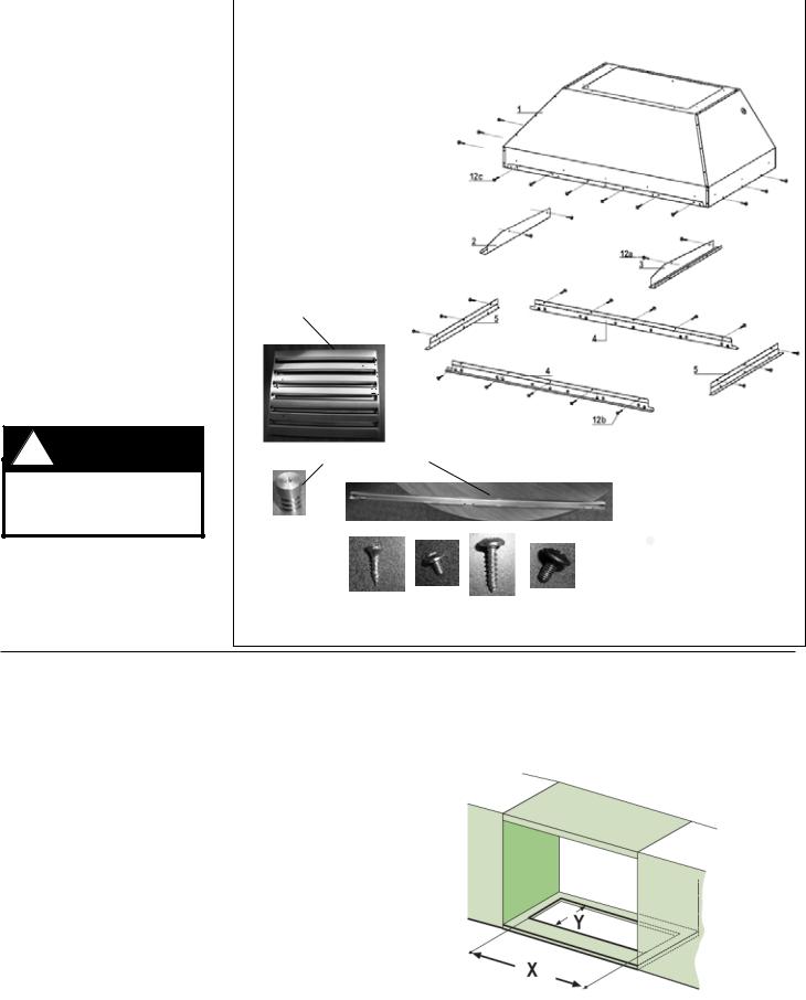
RANGEHOOD COMPONENTS |
|
|
||||||||||||||||||
1. |
Hood body with lights and controls |
|
|
|
|
|
|
|
|
|
|
|
|
|
|
|
|
|
||||
2. |
Left Side Rail |
|
|
|
|
|
|
|
|
|
|
|
|
|
|
|
|
|
|
|
|
|
3. |
Right Side Rail |
|
|
|
|
|
|
|
|
|
|
|
|
|
|
|
|
|
|
|
|
|
4. |
(2) front / back trim |
|
|
|
|
|
|
|
|
|
|
|
|
|
|
|
|
|
|
|
|
|
5. |
(2) left/right trim |
|
|
|
|
|
|
|
|
|
|
|
|
|
|
|
|
|
|
|
||
|
|
|
|
1 |
|
|
|
|
|
|
|
|
|
|
|
|
|
|||||
6. grease filters (3 - 36/42" / 4 - 48") |
|
|
|
|
|
|
|
|
|
|
|
|
|
|
|
|
|
|||||
7. filter knobs (6 - 36,42" / 8 - 48") |
|
|
|
|
|
|
|
|
|
|
|
|
|
|
|
|
|
|||||
8. grease rail |
|
|
|
|
|
|
|
|
|
|
|
|
|
|
|
|
|
|
|
|
|
|
9a. (4) side rail screws |
|
|
|
|
|
|
|
|
|
|
|
|
|
|
|
|
|
|
|
|
|
|
9c |
|
|
|
|
|
|
|
|
|
|
|
|
|
|
|
|
|
|||||
9b. (16) trim screws |
|
|
|
|
|
|
|
|
|
|
|
|
|
|
|
|
|
|
|
|
|
|
9c. (12) install screws |
|
|
|
|
|
|
|
|
|
|
|
|
|
|
|
|
|
|
|
|
|
|
9d. (6 - 36,42", 8 - 48") filter knob screws |
|
|
|
|
|
|
|
|
|
|
|
|
|
|
|
|
|
|||||
|
|
|
2 |
|
|
|
|
|
|
|
|
|
|
|
|
|
|
|
|
|
|
|
|
|
|
|
|
|
|
|
|
|
|
|
|
9a |
|
|
|
|
|||||
|
|
|
|
|
|
|
|
|
|
|
|
|
|
|
|
|
|
|
|
|
||
|
|
|
|
|
|
|
|
|
|
|
|
|
|
|
|
|
|
|
|
|
|
|
|
|
|
|
|
|
|
|
|
|
|
|
|
|
|
|
|
3 |
|
|
|
||
|
6 |
|
|
|
|
|
|
|
|
|
|
|
|
|
|
|
|
|
|
|
|
|
|
|
|
|
|
|
5 |
|
|
|
|
|
|
|
|
|
|
|
|
|
|
|
|
|
|
|
|
|
|
|
|
|
|
|
|
|
|
|
|
|
|
|
|
|
|
|
|
|
|
|
|
|
|
|
|
|
|
|
|
|
|
|
|
|
|
|
|
|
|
|
|
|
|
|
|
4 |
|
|
|
|
|
|
|
|
||||||||
|
|
|
|
|
|
|
|
|
|
|
|
|
|
|
|
|
|
|
|
|
||
|
|
|
|
|
|
|
|
|
|
|
|
|
|
5 |
|
|||||||
|
|
|
|
|
|
4 |
|
|
|
|
|
|
|
|
|
|
||||||
|
|
|
|
|
|
|
|
|
|
|
|
|
|
|
|
|||||||
|
|
|
|
|
|
|
|
|
|
|
|
|
|
|
|
|
|
|
|
|
||
|
|
|
|
|
|
|
|
|
|
|
|
|
9b |
|
|
|||||||
|
7 |
8 |
|
|
|
|
|
|
|
|
|
|
|
|
|
|
|
|
|
|
|
|
9a |
9b |
9c |
9d |
FIGURE 1
MAKING THE CABINET CUT OUT
This hood can be installed directly into a cabinet without a liner using 12 of the 9c screws (FIGURE 1). The liner is built into the hood already.
1. Cut the opening in the bottom of the cabinet according to the chart below (FIGURE 2, 3)
|
|
|
|
|
|
Outside Hood |
Model # |
X |
Y |
|
|
Dimension |
|
|
|||
36" x 19" |
INPL3619SS |
34 3/4" |
19 3/4" |
|
|
36" x 22" |
INPL3622SS |
34 3/4" |
22 3/4" |
|
|
42" x 19" |
INPL4219SS |
40 3/4" |
19 3/4" |
|
|
48" x 19" |
INPL4819SS |
46 3/4" |
19 3/4" |
|
|
48" x 22" |
INPL4822SS |
46 3/4" |
22 3/4" |
|
|
|
|
|
FIGURE 3 |
|
FIGURE 2 |
|
|
|
|
|
|
Version 07/11 - Page 5
INSTALLATION
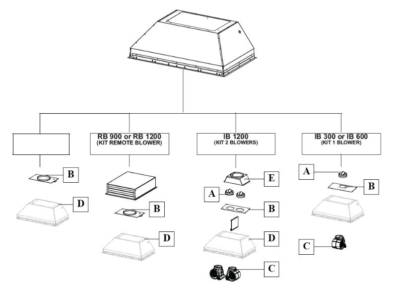
COMBINATIONS HOOD AND MOTOR KITS
INLBKIT
CAUTION - To reduce risk of fire and electric shock, install this rangehood only with: Remote blower manufacturer by Faber models RB900 and RB1200 or Integral blower manufactured by Faber models IB300 or IB600 or IB1200 or with INLBKIT and generic in-line blower rated max 4.2 A suitable for use with solid state variable speed control
CHOOSE A BLOWER FOR YOUR HOOD
After choosing the hood width and depth for your cooking
needs, next choose the type of blower appropriate for
your cooking. NOTE: no other blower is compatible with this hood, except for the kits below.
# IB300 - Internal Blower Kit 300 cfm
# IB600 - Internal Blower Kit 600 cfm
# IB1200 - Internal Blower Kit 1200 cfm
# RB900 - Remote Blower Kit 900 cfm
# RB1200 - Remote Blower Kit 1200 cfm
# INLBKIT - In Line Blower Kit
(supply own in-line blower)
OPTIONAL ACCESSORIES AVAILABLE
• *Charcoal Filter
* it is highly recommended that professional style cooking always be vented to the outside; for recirculating installations only, some ductwork is required to exhaust the unit out of the cabinet. Replace as needed with the
same model
part # FILTER1
NOTE: The charcoal filter kit for use with the 300 / 600 cfm internal blower kit ONLY
Version 07/11 - Page 6
 Loading...