


EIED55HIW
1
137032700B (0209)
Dryer Tech Data Sheet
This information is intended for Qualified T echnicians Only.
CAUTION: DISCONNECT ELECTRICAL CURRENT BEFORE SERVICING
Please Return This Sheet to its Envelope in the Product for Future Reference
Acronym Table
CW – Clockwise
CCW – Counter Clockwise
READING ERROR CODES
1. Wake the dryer up by pressing any button but “cancel”.
2. Press and hold the “cancel” and “start pause” buttons simultaneously for 6 seconds to show the last error
code recorded. The error code will appear in the display as an E followed by two numbers. NOTE: E00
means no failure code experienced.
3. T o view the last 5 error codes recorded, refer to the Diagnostic Mode listed below .
4. Troubleshoot problem by using the chart below .
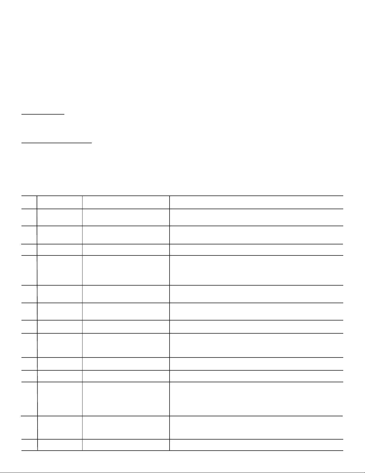
Error
Code
E31
E32
E42
E51
E52
E53
E54
E61
E63
E64
E65
E66
E67
Fault
Contact Sensor
frequency too high
Contact Sensor
frequency too low
Door Sensing
failure
Motor Relay failure
Motor Fault –
motor stopped or
not starting
Motor Centripetal
Switch Failure
Motor Sensing
failure
Heater Relay
failure
Heater to Earth
Ground
Heater Open
Circuit
High Limit
Thermostat trip
count too high
Thermal Limiter
Open Circuit
Heaters Sensing
Failure
Possible Fault Conditions
Electronic Control Board defective or
foreign object interfering with contact
sensor
Electronic Control Board defective or
foreign object interfering with contact
sensor
Electronic Control Board defective
Motor Relay stuck open or closed;
Wiring defective
Motor overheating; Laundry load too
heavy; Low power supply; Motor, or
Wiring defective
Motor Centripetal Switch, Electronic
Control Board Defective, or wiring
defective.
Electronic Control Board defective
Heater relay stuck open or closed;
Wiring defective
Heating element or wiring defective
Heating element or wiring defective
High vent restriction, High Limit
Thermostat defective or Inlet Thermal
Limiter tripped (Electric Model only)
Outlet Thermal Limiter tripped Inlet
Thermal Limiter tripped (Gas
Model only) or wiring defective
Electronic Control Board defective
Possible Solutions
Check Contact Sensor and wiring. If no problems are found with Contact
Sensor, replace Electronic Control Board.
Check Contact Sensor and wiring. If no problems are found with Contact
Sensor, replace Electronic Control Board.
Replace Electronic Control Board.
If motor runs continuously with power applied check for short circuit across
motor relay (RL2), or L1 applied to motor relay output (J3-1) with cycle
stopped. If motor does not start when “start” key is pressed, check for open
circuit between L1 and motor relay connection (J3-2). If no wiring problems
found, replace Electronic Control Board.
Remove any load from dryer and check if drum turns freely by hand. Check
L1 power supply voltage, motor wiring, and motor thermal protector (if motor
thermal protector has tripped, it may take up to 30 minutes to reset).
Check wiring. Check if Motor Centripetal Switches are stuck in open or closed
positions. Replace motor. Replace Electronic Control Board.
Replace Electronic Control Board and retest.
Check for short circuit across heater relay(s) (RL5, RL6, RL7) or L1 applied
to heater relay output(s) (J5-2, J7-1, J7-3) with cycle stopped. Check for
open circuit between L1 and heater relay connection(s) (J5-1, J5-3, J7-2). If
no wiring problems are found, replace Electronic Control Board and retest.
Check heater coils and connections for short circuits to the cabinet. Replace
heater and/or wiring and retest.
Check heater coils and connections for open circuits. Replace heater and/or
wiring and retest.
For Electric Model, check Inlet Thermal Limiter for continuity. If Thermal Limiter
is open, check for evidence of high temperature event and any resulting
damage. If no further damage is evident, replace Thermal Limiter. If no
problems are found with the Thermal Limiter, check exhaust vent system for
air blockages. If no problems with vent restrictions, check/replace High Limit
Thermostat, and retest.
Check Outlet Thermal Limiter for continuity. For Gas Model, also check Inlet
Thermal Limiter for continuity. If Thermal Limiter is open, check for evidence
of high temperature event and any resulting damage. If no further
damage is evident, replace Thermal Limiter and retest.
Replace Electronic Control Board and retest.
Contents Page
Error code explanation.............................................1
Error Code Chart....................................................1-2
Diagnostics .................................................................3
Français…………………………………………......4-6
Español…………………………………………..............7-9
Wiring Diagram…………………………………….......10-11
2
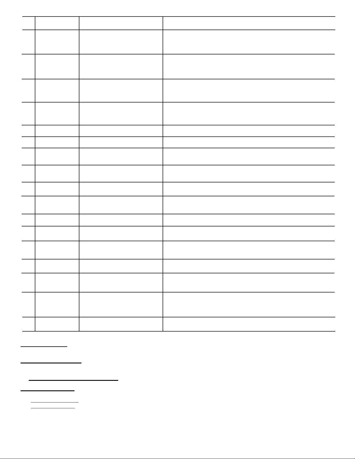
Error
Code
E71
E72
E73
E74
E91
E92
E93
E94
E97
EA1
EA2
EA3
EA4
EA5
EF1
EF3
EF8
Fault
Outlet Control
Thermistor open
circuit
Outlet Control
Thermistor short
circuit
Inlet Control
Thermistor open
circuit
Inlet Control
Thermistor short
circuit
Communication
Error
Incompatible
protocol
Machine
configuration
checksum error
Cycle configuration
checksum error
Program mismatch
Main Supply
Frequency out of
Range
Voltage too high
Voltage too low
Improper home
wiring
Main V Sensing
failure
Vent Blocked
Max Timeout Timer
Key Stuck
Possible Fault Conditions
Outlet Control Thermistor or wiring
defective
Outlet Control Thermistor or wiring
defective
Inlet Control Thermistor or wiring
defective
Inlet Control Thermistor or wiring
defective
Wiring, Electronic Control Board, or
Interface Board defective
Electronic Control Board incompatible
with Interface Board
Wrong configuration data loaded,
Interface Board or Electronic Control
Board or wiring defective
Wrong configuration data loaded or
Electronic Control Board defective
Wrong configuration data loaded,
Electronic Control Board defective
Line frequency out of limits or
Electronic Control Board faulty
Line voltage too high or Electronic
Control Board faulty
Line voltage too low or Electronic
Control Board faulty
Line connections in home faulty,
wiring or Electronic Control Board
defective
Electronic Control Board defective
High vent restriction, Exhaust Control
Thermistor, Inlet Control Thermistor, or
Electronic Control Board defective
Exhaust blocked; Exhaust Control
Thermistor, Inlet Control
Thermistor, Contact Sensor or
Electronic Control Board defective
Console button or Interface Board
defective
Possible Solutions
Check resistance of Outlet Control Thermistor, and check wiring for open circuit.
Resistance should be between 4.9K Ohm and 6.2K Ohm at room temperature
(68-77° F or 20-25° C). Replace Outlet Control Thermistor and/or wiring and
retest.
Check resistance of Outlet Control Thermistor, and check wiring for short circuit
across Thermistor connections. Resistance should be between 4.9K Ohm and
6.2K Ohm at room temperature (68-77° F or 20-25° C). Replace Outlet Control
Thermistor and/or wiring and retest.
Check resistance of Inlet Control Thermistor, and check wiring for open circuit.
Resistance should be between 47K Ohm and 66K Ohm at room temperature
(68-77° F or 20-25° C). Replace Inlet Control Thermistor and/or wiring and
retest.
Check resistance of Inlet Control Thermistor, and check wiring for short circuit
across Thermistor connections. Resistance should be between 47K Ohm and
66K Ohm at room temperature (68-77° F or 20-25° C). Replace Inlet Control
Thermistor and/or wiring and retest.
Check connections between Electronic Control Board and Interface Board. If no
wiring problems, replace Electronic Control Board or Interface Board.
Check if correct Interface Board console and Electronic Control Board are
installed. Replace appropriate hardware.
Check if correct Interface Board and console are installed. Replace Interface
Board and/or console.
Replace Electronic Control Board.
Replace Electronic Control Board.
Check frequency of line voltage.
Check amplitude of line voltage.
Check amplitude of line voltage.
Check wiring at terminal block for L1-N-L2 wired incorrectly.
Replace Electronic Control Board.
Check vent restrictions and resistance values of Exhaust Control Thermistor
and Inlet Control Thermistor.
Check vent restriction, Contact Sensor, and resistance values of Exhaust
Control Thermistor and Inlet Control Thermistor
Check buttons for activation when pressed. Replace console or Interface Board
as appropriate
FACTORY RESET
1. Press and hold the “Temperature” and “Dryness” buttons simultaneously for 6 seconds.
INST ALLATION CYCLE
1. Use the selector knob to select the “touch up” cycle
2. Press and hold the “my favorite” and “sanitize” buttons simultaneously for 6 seconds.
3. Remove any load from the dryer and press “start pause” to start installation cycle.
DIAGNOSTIC MODE
1. Press the “cancel” button to enter standby mode and enable diagnostic entry.
2. Within 10 seconds after pressing “cancel”, press any button (but “cancel”) to wake up the control.
3. Within 5 seconds of wake up, turn the selector knob to the far left cycle and press and hold the “cancel” and the far left
button under the display simultaneously for 3 seconds to enter the Diagnostic Mode. (note: to save time at wake up,
the welcome screen can be bypassed by turning the selector knob).
4. Upon entering Diagnostic Mode, all lights should flash on and off.
5. The following steps can be cycled through by turning the selector knob clockwise:
3
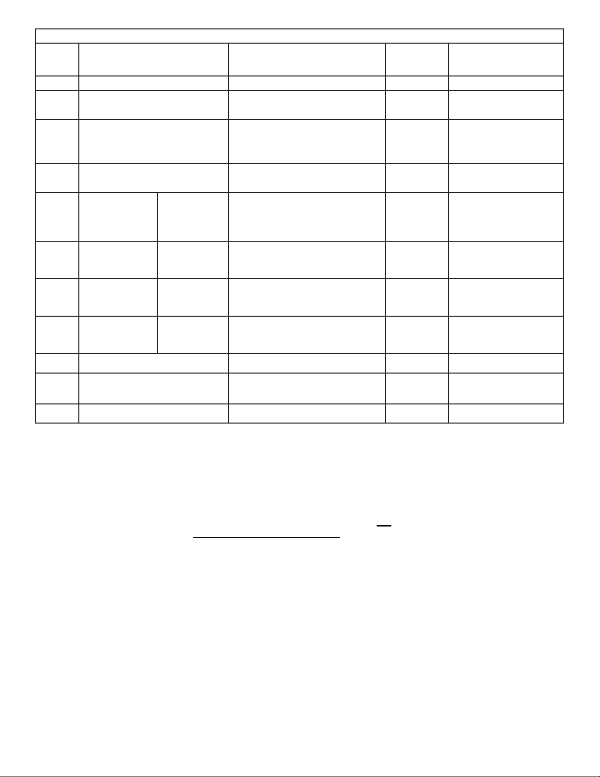
Diagnostic Mode
Selector Test/Activated Component Operator Check LCD row LCD digit s
Position Electric Gas
NOTE : To clear the error code (s): Press and hold the far lef t key under the display and “cancel” buttons
simultaneously for 3 seconds.
6. T o exit Diagnostic Mode:
a) Unplug the power cord, wait 5-8 seconds, then reconnect the power cord OR
b) T urn the program knob to the Start Position (lights/Buttons Test). Press the “cancel” and far lef t button under the
display simultaneously for 6 seconds.
0
1
2
3
4
5
6
7
8
9
10
Lights / Buttons test
Motor Clockwise (CW)
Contact Sensor
Motor Clockwise (CW)
Lights / Buttons
test + Motor CW
Motor CW + Heater
1
Motor CW + Heater
1 + Heater 2
Motor CW + Heater
1 + Heater 2 +
Heater 3
Lights / Buttons
test + Motor CW +
igniter
Motor CW +
Heater
Motor CW +
Heater
Motor CW +
Heater
Motor Clockwise (CW)
Error code history display
Software version
Check Motor function. Look for Drum
rotation in clockwise direction
Check moisture reading. Place fingers
across Contact Sensor and look for digit
display to change from “1
111” to “8888”
Check Motor function. Look for Drum
rotation in clockwise direction
Check all buttons and lights. Press all
buttons and check for beep and button
ID number in digit display. Check to see
that all Lights function
Check Motor and Heater function. Check
Outlet Control Thermistor value in digit
display.
Check Motor and Heater function. Check
Inlet Control Thermistor value in digit
display.
Check Motor and Heater function. Check
Outlet Control Thermistor value in digit
display.
Check last 5 error codes displayed (See
Table above for error code definitions)
Software version
“MOTOR CW”
“MOIST . BARS”
“MOTOR CW”
“HEAT1 - NTC1”
“HEAT2 - NTC2”
“HEAT3 - NTC1”
“MOTOR CW”
Software
version
“1111” if Contact Sensor
open circuit;”8888" if
Contact Sensor short
circuited
button id number
Outlet Control Thermistor
value (degrees F)
Inlet Control Thermistor
value (degrees F)
Outlet Control Thermistor
value (degrees F)
error code
Software version
4
Fiche de données techniques de sécheuse
Informations réservées aux techniciens qualifiés.
A TTENTION : DÉBRANCHEZ L’ALIMENT A TION ÉLECTRIQUE A V ANT D’EFFECTUER TOUT ENTRETIEN
Replacez cette fiche dans son enveloppe dans l’appareil pour référence ultérieure
Tableau des acronymes
SH - Sens horaire
SAH - Sens antihoraire
LECTURE DES CODES D’ERREUR
1. Réveillez la laveuse en appuyant sur une touche quelconque, sauf “cancel (annuler)”.
2. Appuyez et maintenez simultanément appuyées les touches “cancel (annuler)” et “start (départ)/ pause” pendant 6
secondes pour afficher le dernier code d’erreur enregistré.
Le code d’erreur s’affiche à l’écran sous la forme d’un E suivi de deux chiffres. REMARQUE : E00 signifie qu’il n’existe
aucun code d’erreur.
3. Pour afficher les 5 derniers codes d’erreur enregistrés, référez-vous au mode Diagnostic listé ci-dessous.
4. Vérifiez la source du problème en utilisant le tableau ci-dessous.
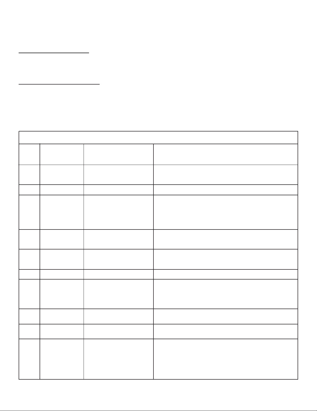
Code
d’erreur Anomalie États d’anomalie Solutions
E31
E32
E42
E51
E52
E53
E54
E61
E63
E64
E65
Fréquence du
capteur à contact
trop élevée
Fréquence du
capteur à contact
trop basse
Défaillance du
capteur de la porte
Défaillance du
relais du moteur
Anomalie moteur -
le moteur est
arrêté ou ne
démarre pas
Défaillance de
l’interrupteur du
moteur de type
centripète
Défaillance du
capteur du moteur
Défaillance du
relais de l’élément
chauffant
Élément chauffant
à la terre
Élément chauffant
avec indication de
court-circuit
Nombre de
déclenchements
du thermostat de
limite-haute trop
élevé
Carte de contrôle électronique
défectueuse ou corps étranger
interférant avec le capteur à
contact
Carte de contrôle électronique
défectueuse ou corps étranger
interférant avec le capteur à
contact
Carte de contrôle électronique
défectueuse
Relais du moteur bloqué en
position ouverte ou fermée ;
Câblage défectueux
Surchauffe du moteur ; Le linge
est trop lourd ; Tension
d’alimentation basse ; Moteur ou
câblage défectueux
Interrupteur du moteur de type
centripète, carte de contrôle
électronique ou câblage
défectueux.
Carte de contrôle électronique
défectueuse
Relais de l’élément chauffant
bloqué en position ouverte ou
fermée ; Câblage défectueux
Élement chauffant ou câblage
défectueux
Élement chauffant ou câblage
défectueux
Évent haut obstrué, thermostat
de limite-haute défectueux ou
déclenchement limiteur
thermique d’entrée (modèle
électrique uniquement)
Vérifiez le capteur à contact et le câblage. Si le capteur à contact ne
présente aucun problème, remplacez la carte de contrôle électronique et
faites un nouveau test.
Vérifiez le capteur à contact et le câblage. Si le capteur à contact ne
présente aucun problème, remplacez la carte de contrôle électronique et
faites un nouveau test.
Remplacez la carte de contrôle électronique et faites un nouveau test.
Si le moteur fonctionne continuellement sous tension, vérifiez la présence
d’un court-circuit au niveau du relais du moteur (RL2), ou L1 à la sortie du
relais du moteur (J3-1) lorsque le cycle est arrêté. Si le moteur ne démarre
pas lorsque vous appuyez sur la touche “start (départ)”, vérifiez si le
circuit est ouvert entre L1 et la connexion du relais du moteur (J3-2). Si le
câblage ne présente aucun problème, remplacez la carte de contrôle
électronique et faites un nouveau test.
Retirez le linge de la sécheuse et vérifiez si le tambour tourne librement
avec la main. Vérifiez la tension de l’alimentation L1, le câblage et le
protecteur thermique du moteur (si le protecteur thermique s’est déclenché,
la réinitialisation peut prendre jusqu’à 30 minutes).
Vérifiez le câblage. Vérifiez si les interrupteurs du moteur de type
centripète sont bloqués en position ouverte ou fermée. Remplacez le
moteur. Remplacez la carte de contrôle électronique.
Remplacez la carte de contrôle électronique et faites un nouveau test.
Vérifiez la présence d’un court-circuit entre les relais de l’élément
chauffant (RL5, RL6, RL7) ou L1 appliqué aux sorties du relais de l’élément
chauffant (J5-2, J7-1, J7-3) lorsque le cycle est arrêté. Vérifiez si le
circuit est ouvert entre L1 et les connexions du relais de l’élément chauffant
(J5-1, J5-3, J7-2). Si le câblage ne présente aucun problème, remplacez
la carte de contrôle électronique et faites un nouveau test.
Vérifiez les bobines de l’élément chauffant et les connexions à la recherche
de courts-circuits dans la carrosserie. Remplacez l’élément chauffant et/
ou le câblage et faites un nouveau test.
Vérifiez les bobines de l’élément chauffant et les connexions à la recherche
de circuits ouverts. Remplacez l’élément chauffant et/ou le câblage et
faites un nouveau test.
Pour le modèle électrique, vérifiez la continuité du limiteur thermique
d’entrée. Si le limiteur thermique est ouvert, vérifiez s’il existe des indices
de dommages résultant de températures élevées. S’il n’existe aucune
évidence de dommage, remplacez le limiteur thermique. Si le limiteur
thermique ne présente aucun problème, vérifiez si le système d’évacuation
est obstrué. Si ce système n’est pas obstrué, vérifiez/remplacez le
thermostat de limite-haute, et faites un nouveau test.
 Loading...