


PT-17
Stearman PT-17 15e ARF
Assembly Manual
Specifications
Wingspan 44 in (1117mm)
Length 35 in (889mm)
Wing Area 608 sq in (37.5 sq dm)
Weight with Battery 3.5–3.8 lb (1.5–1.7 kg)
Weight without Battery 3.1–3.3 lb (1.4–1.5 kg)
Pilots not included (available separately)

Table of Contents
Product Registration......................................................2
Introduction ...............................................................2
Warranty Information................................................. 2
Using the Manual...................................................... 2
Contents of Kit/Parts Layout........................................ 2
Recommended Radio Equipment...................................3
Recommended Equipment.............................................3
Optional Accessories....................................................3
Required Tools and Adhesives.......................................3
Warning.....................................................................3
Note on Lithium Polymer Batteries..................................3
Rudder and Elevator Servo Installation............................4
Stabilizer and Fin Installation.........................................5
Rudder and Elevator Pushrod Installation........................8
Landing Gear Installation............................................11
Cabane Strut and Center Section Installation.................11
Aileron Installation.....................................................15
Aileron Linkage Installation.........................................16
Motor and ESC Installation..........................................17
Cowling Installation....................................................18
Interplane and Wing Transport Jig Installation...............19
Battery Installation......................................................22
Receiver Installation....................................................23
Wing Installation........................................................24
Center of Gravity........................................................25
Control Throws...........................................................26
Preflight.....................................................................26
Safety, Precautions and Warnings...............................27
Age Requirements......................................................27
Safety Do’s and Don’ts for Pilots...................................27
Warranty Information.................................................28
2009 Official Academy of Model
Aeronatics Safety Code........................................30
Instructions for Disposal of WEEE by
Users in the European Union................................31
Product Registration
Registering your product will provide you the option
to stay up-to-date on product information, new
products, customization options and other information
for E-flite owners. Register your product today at
www.E-fliteRC.com/register.
Introduction
The Stearman PT-17 was a primary flight trainer used by
the U.S. Army Air Corps (USAAC) during World War II.
The PT-17 was a conventional biplane design with an
open, two-place cockpit to accommodate a student and
instructor, in tandem. The aircraft was constructed with
wood wings and a welded steel fuselage, all covered
with fabric. The plane became highly recognizable with
its biplane design and exposed radial engine. The
PT-17 was known as a rugged aircraft and an excellent
trainer. The PT-17 was designed by the Stearman
Aircraft Corporation and in 1934 Boeing purchased the
company. Boeing manufactured over 10,500 PT-17s and
when production ended it became known as the last
production military biplane built in the United States.
Important Warranty Information
Please read our Warranty and Liability Limitations
section on page 25 before building this product. If you
as the Purchaser or user are not prepared to accept the
liability associated with the use of this Product, you are
advised to return this Product immediately in new and
unused condition to the place of purchase.
Using the Manual
This manual is divided into sections to help make
assembly easier to understand, and to provide breaks
between each major section. In addition, check boxes
have been placed next to each step to keep track
of its completion. Steps with a single circle (Ο) are
performed once, while steps with two circles (Ο Ο)
indicate that the step will require repeating, such as for
a right or left wing panel, two servos, etc.
Remember to take your time and follow the directions.
Contents of Kit/Parts Layout
Replacement Parts
EFL2951T Top Outboard Wing Set
EFL2951C Center Top Wing
EFL2951B Bottom Wing Set
EFL2952 Fuselage with Hatch
EFL2953 Tail Set
EFL2954 Cowling with Dummy Motor
EFL2955 Wing Tube Set
EFL2956 N Wing Strut Set
EFL2957 Cabane Strut Set
EFL2958 Main Landing Gear Set
EFL2959 Tail Wheel Set
EFL2960 Windscreen Set
EFL2961 Pushrod Set
EFL2962 Wing Transport Jigs
EFL2963 Hatch
EFL2964 Hardware Pack
E-flite Stearman PT-17 15e ARF Assembly Manual
2
2
Recommended Radio Equipment
You will need a minimum of a 4-channel transmitter,
receiver and four servos. You can choose to purchase a
complete radio system, or if you are using an existing
transmitter, just purchase the other required equipment
separately. We recommend the crystal-free, interference-
free Spektrum™ DX5e 2.4GHz DSM® 5-channel system.
If using your own transmitter, we recommend the JR
SPORT MN48 and MC35 servos.
If you own a Spektrum radio, just add a DSM2™
receiver, two JR SPORT MN48, and two JR SPORT
MC35 servos. We show the installation of the AR500
receiver in this manual.
Radio System
SPM5500 DX5e DSM2 5CH system
Or Purchase Separately
any of the Following Receiver
s
SPMAR500 AR500 DSM2 5-Channel Full-Range
Receiver (for DX5e, DX6i, or DX7)
SPMAR6200 AR6200 DSM2 6-Channel Full Range
Receiver (for DX5e, DX6i, or DX7)
And
JSP20040 MN48 Mini Servo (2)
JSP20030 MC35 Micro Servo (2)
JRPA096 9-inch Servo Extension (2)
Recommended Equipment
EFLM4015A Power 15 Brushless Outrunner 950Kv
EFLA1040 40A Pro Brushless ESC
EFLB32003S 3200mAh 3S 11.1V 20C Li-Po
APC12060E Electric Propeller 12 x 6E
Optional Accessories
EFLA110 Power Meter
EFLC3005 Celectra™ 1- to 3-Cell Li-Po Charger
EFLC505 Intelligent 1- to 5-Cell Balancing
Charger
EFLA150 Military Pilot (1 or 2)
Required Tools and Adhesives
Tools & Equipment
Manila card stock Pliers
Low-tack tape Pencil
Pin vise Clear tape
Ruler Hook and loop tape
T-pins Philips screwdriver: #0, #1
Felt-tipped pen Hobby knife (#11 blade)
Mixing sticks Toothpicks
1/16-inch drill bit Sidecutters
Rubbing alcohol Paper towels
Double-sided tape Cable tie
Stick-on lead weight Square
Mixing cups
Allen wrench or balldriver: 3/32-inch, 7/64-inch
Adhesives
Thin CA Medium CA
Threadlock 6-minute epoxy (HAN8000)
Warning
An RC aircraft is not a toy! If misused, it can cause
serious bodily harm and damage to property. Fly only in
open areas, preferably at AMA (Academy of Model
Aeronautics) approved flying sites, following all
instructions included with your radio. Keep loose items
that can get entangled away from the propeller,
including loose clothing, or other objects such as pencils
and screwdrivers. Especially keep your hands away from
the propeller.
Note on Lithium Polymer Batteries
During the course of building your PT-17
ARF we suggest that you use a soft surface
for the building surface. A foam stand, large
piece of bedding foam or a thick bath towel
will work well and help protect the model
from damage during assembly.
Lithium Polymer batteries are
significantly more volatile than
alkaline or Ni-Cd/Ni-MH
batteries used in RC applications.
All manufacturer’s instructions and
warnings must be followed closely.
Mishandling of Li-Po batteries can
result in fire. Always follow the
manufacturer’s instructions when
disposing of Lithium Polymer
batteries.
E-flite Stearman PT-17 15e ARF Assembly Manual
3
3
Rudder and Elevator Servo Installation
Parts Required
Fuselage assembly Mini servos with hardware (2)
Radio system JR MatchMaker
Tools Required
Pin vise 1/16-inch drill bit
Sidecutters Thin CA
Felt-tipped pen Philips screwdriver #0
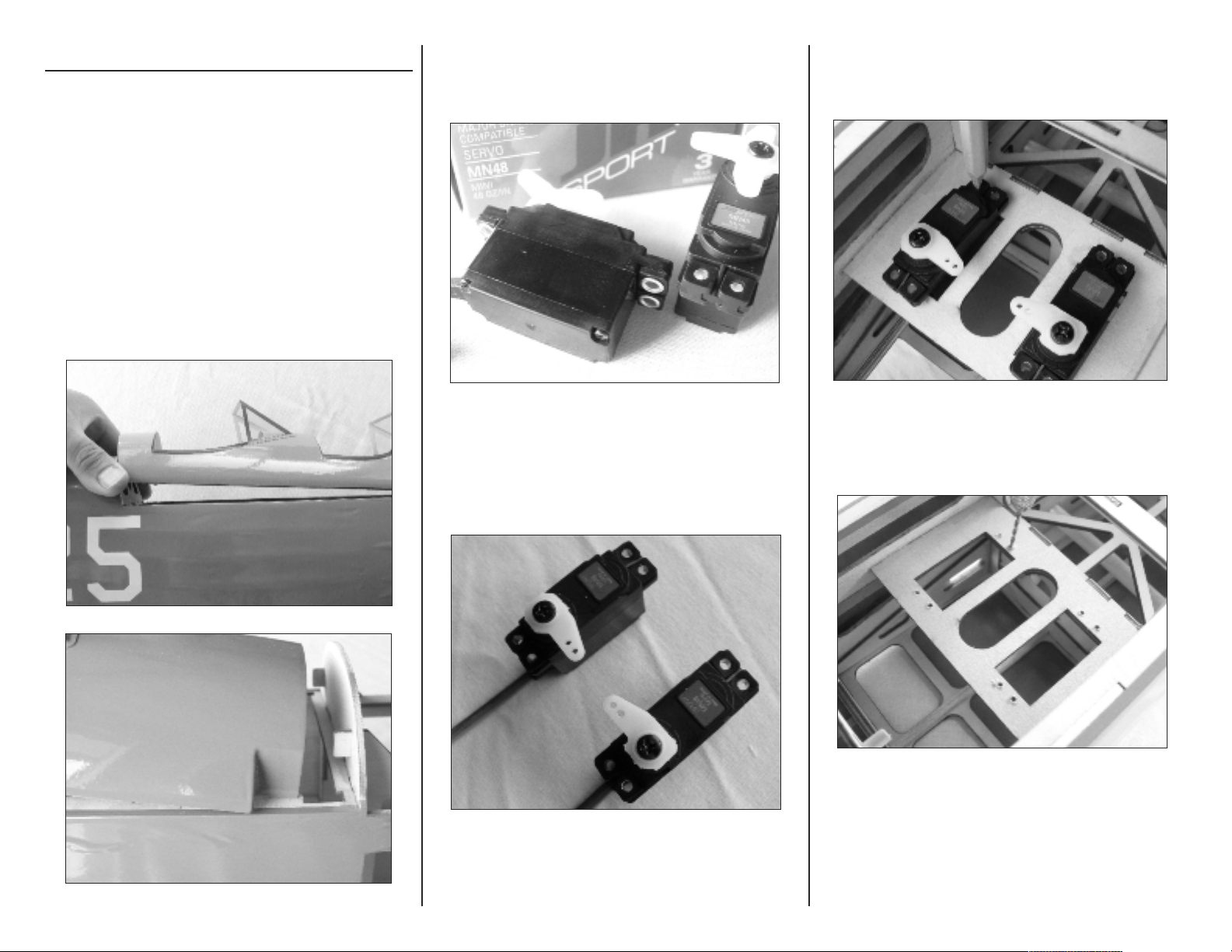
Ο 1. Remove the cockpit hatch by lifting at the rear then
pulling aft to disengage the tabs at the forward
end. Set the hatch aside.
Ο 2. Install the grommets and bushings in the rudder
and elevator servos. Note that the bushing is
installed from the bottom of the mounting lugs.
Ο 3. Center the servos using your radio or a JR
MatchMaker. Using sidecutters, remove three of
the arms from each standard servo horn,
leaving one long arm on each as shown.
Ο 4. Place the rudder and elevator servos in the
fuselage servo cutouts and mark the mounting
holes with a felt-tipped pen.
Ο 5. Remove the servos. Use a 1/16-inch drill bit
in a pin vise to drill the mounting holes.
E-flite Stearman PT-17 15e ARF Assembly Manual
4
4
Ο 6. Apply 2-3 drops of thin CA to each mounting
screw hole to strengthen the wood. This will
make the servo mounting screws more secure
when installed.
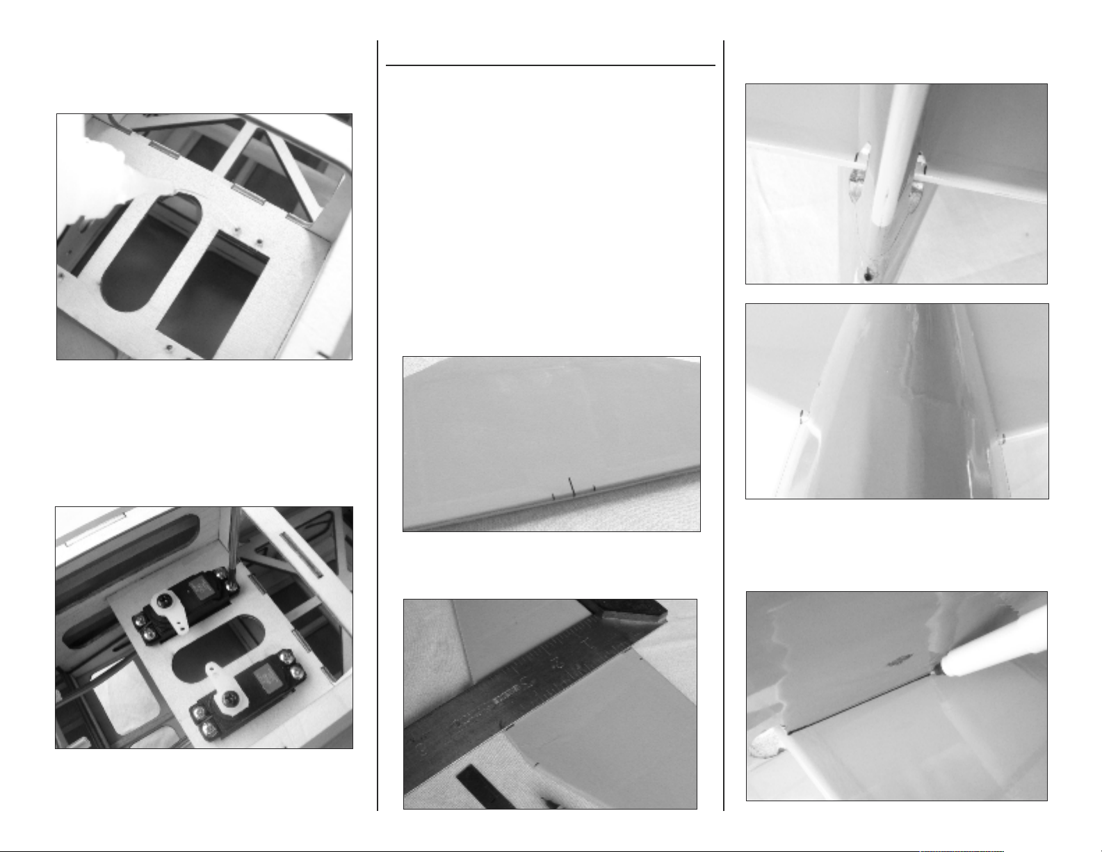
Ο 7. Using a #0 Philips screwdriver and the screws
provided with the servos, install the rudder and
elevator servos in the fuselage with the arms
inboard and towards the rear of the fuselage.
Stabilizer and Fin Installation
Parts Required
Fuselage Stabilizer
Elevator Rudder
CA hinges (8) Tailwheel assembly
Tools Required
Felt-tipped pen Thin CA Ruler
Allen wrench Square Threadlock
Rubbing alcohol Paper towels T-pins
6-minute epoxy Toothpicks Mixing sticks
Mixing cups Hobby knife (#11 blade)
Ο 1. Use a ruler to mark the center of the trailing edge
of the stabilizer. Measure 13/32-inch each side of
center and make a mark using a felt-tip pen.
Ο 2. Use a square to transfer the centerline to the
leading edge, then make a mark 1-1/8-inches
each side of the center.
Ο 3. Slide the stabilizer into the fuselage and align the
marks made with the fuselage sides.
Ο 4. Use a felt-tipped pen to mark the bottom of the
stabilizer along the fuselage sides.
E-flite Stearman PT-17 15e ARF Assembly Manual
5
5
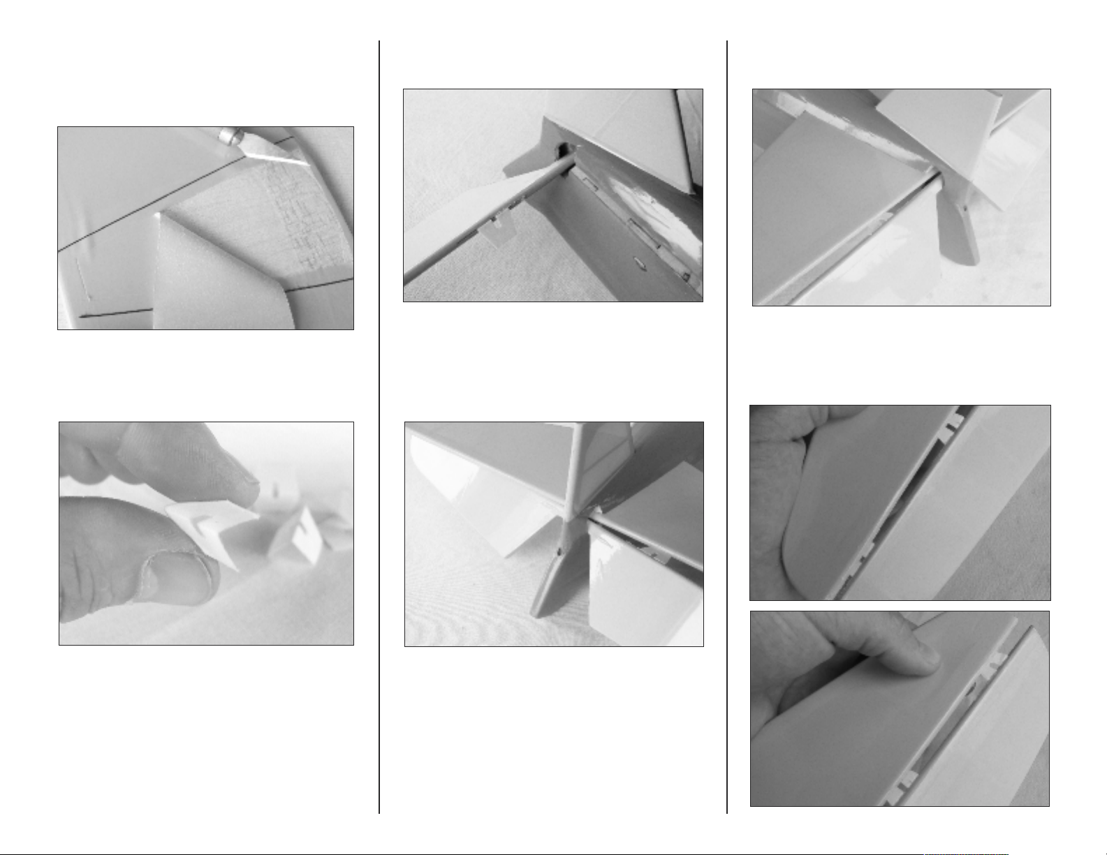
Ο 5. Remove the stabilizer and use a hobby knife with
#11 blade to remove a section of covering
approximately 1/4-inch inside the marked lines,
and the leading and trailing edges.
Ο 6. Prepare six elevator hinges by folding them in
half to form a crease.
Ο 7. Slide the elevator into the fuselage and insert the
six hinges.
Ο 8. Slide the stabilizer into the fuselage. First install the
right side inboard hinge, by angling the elevator
as shown.
Ο 9. Then install the left inboard hinge by angling the
elevator the opposite direction.
Ο 10. Next, insert the left and right center and outboard
hinges in the stabilizer.
E-flite Stearman PT-17 15e ARF Assembly Manual
6
6
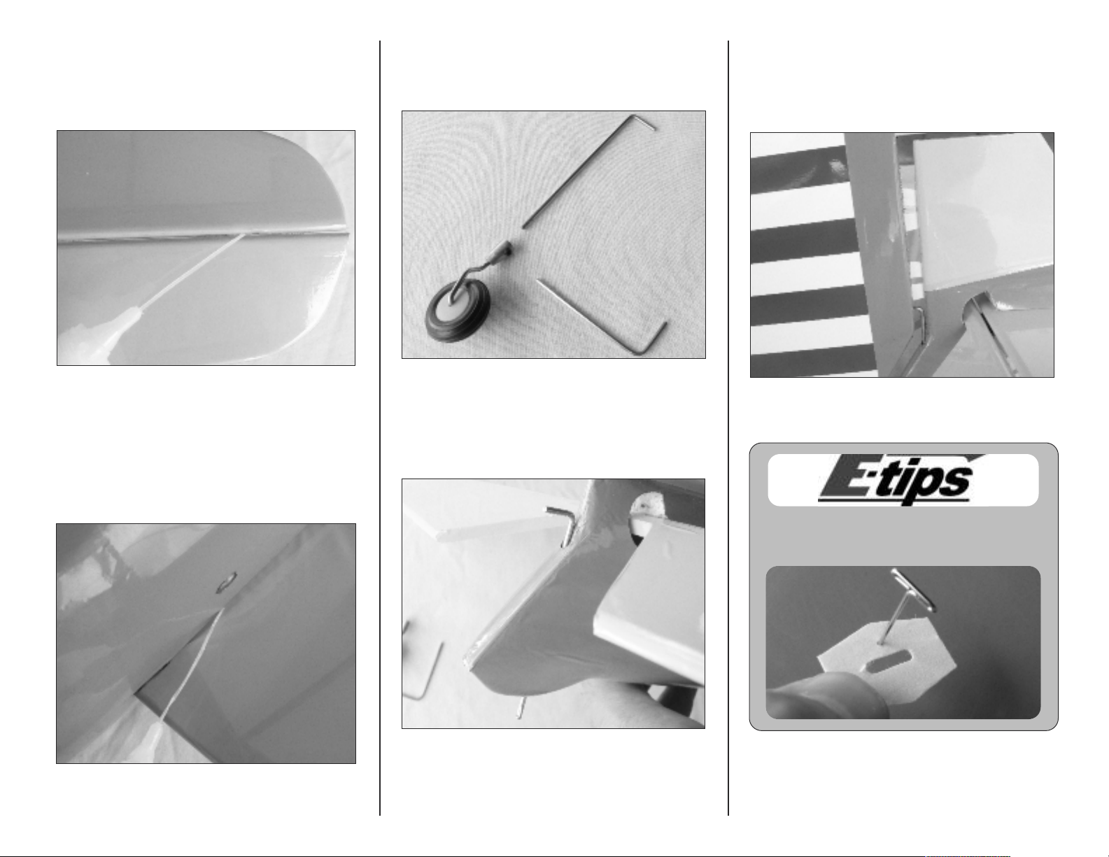
Ο 11. Align the elevator with the stabilizer and apply
2 - 3 drops of thin CA to each hinge. Do not use
accelerator on the hinges as the CA needs to
penetrate the hinge for a complete bond.
Ο 12. Using the marks made in steps 1, 2 and 4, check
that the stabilizer is aligned with the fuselage.
Apply several drops of thin CA to each side of the
joint to glue the stabilizer in place.
Ο 13. Locate the tailwheel assembly. Using the supplied
Allen wrench, separate the tailwheel shaft from the
wheel assembly.
Ο 14. Install the tailwheel shaft in the fuselage.
Ο 15. Install two hinges in the rudder. Mix a small
amount of 6-minute epoxy and apply it to the tail
wheel shaft hole in the rudder with a toothpick,
then slide the rudder assembly on to the fin.
Use rubbing alcohol to clean any excess epoxy.
Use a T-pin in the center of each hinge to ensure
that it remains centered during installation.
E-flite Stearman PT-17 15e ARF Assembly Manual
7
7
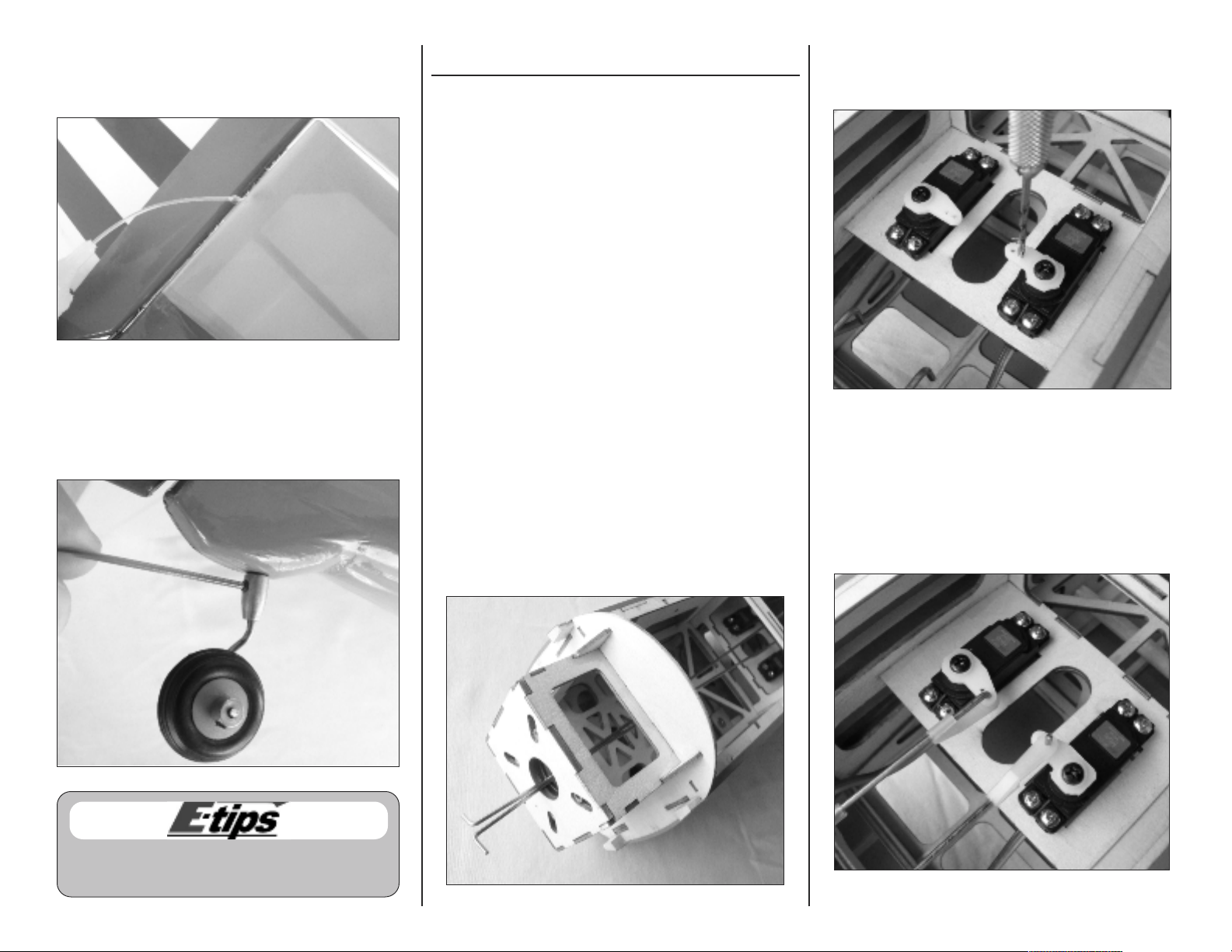
Ο 16. Apply a few drops of thin CA to each rudder
hinge. Do not use accelerator on the hinges so the
CA can penetrate the hinges completely.
Ο 17. Install the tailwheel using the supplied 1.5mm
Allen wrench. Apply a small amount of threadlock
to the setscrew before installation to prevent it from
vibrating loose.
Rudder and Elevator Pushrod Installation
Parts Required
Fuselage assembly
Elevator pushrod wire, 16-1/2-inch (419mm)
Rudder pushrod wire, 17-3/4-inch (451mm)
Nylon control horn backplate (2)
2mm x 10mm machine screw (4)
Nylon control horn (2) Nylon clevis (2)
Nylon pushrod keeper (2) Silicone keeper (2)
Tools Required
Pin vise 1/16-inch drill bit
Pliers Ruler
Felt-tipped pen Thin CA
Philips screwdriver #0 Sidecutters
Ο 1. Locate the rudder and elevator pushrods. The
longer pushrod is for the rudder and installed on
the left hand side. The shorter pushrod is installed
on the right hand side for the elevator.
Insert the pushrods in the guide tubes by feeding
them into the fuselage through the opening in the
center of the firewall.
Ο 2. Use a 1/16-inch drill bit in a pin vise to enlarge
the outer hole in the rudder servo arm and the
inner hole in the elevator servo arm.
Ο 3. Fit the pushrods to the servo arms and secure with
the pushrod keepers. Note that the elevator
pushrod is installed inverted so that the bend in the
wire does not contact the servo case.
E-flite Stearman PT-17 15e ARF Assembly Manual
8
8
Use threadlock on all metal-to-metal fasteners to
keep them from vibrating loose.
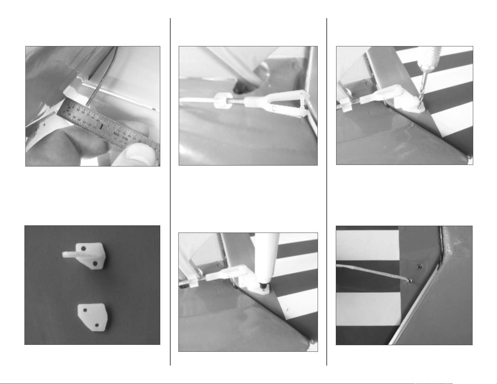
Ο 4. Use a pair of pliers to place a bend in the rudder
pushrod so that the threaded end is 1/2-inch from
the fuselage side.
Ο 5. Use a pair of sidecutters to prepare a control horn
for the rudder by cutting off one corner.
Ο 6. Install a silicone keeper and clevis on the rudder
pushrod so that the clevis pin is aligned with the
rudder hinge line.
Ο 7. Connect the clevis to the control horn. Hold the
control horn in position against the rudder and
mark the screw locations with a felt-tipped pen.
Ο 8. Use the marks and the control horn as reference to
drill the mounting holes with a pin vise and 1/16-
inch drill bit.
Ο 9. Apply 1 - 2 drops of thin CA to each screw hole to
strengthen the wood and stop it from crushing.
E-flite Stearman PT-17 15e ARF Assembly Manual
9
9
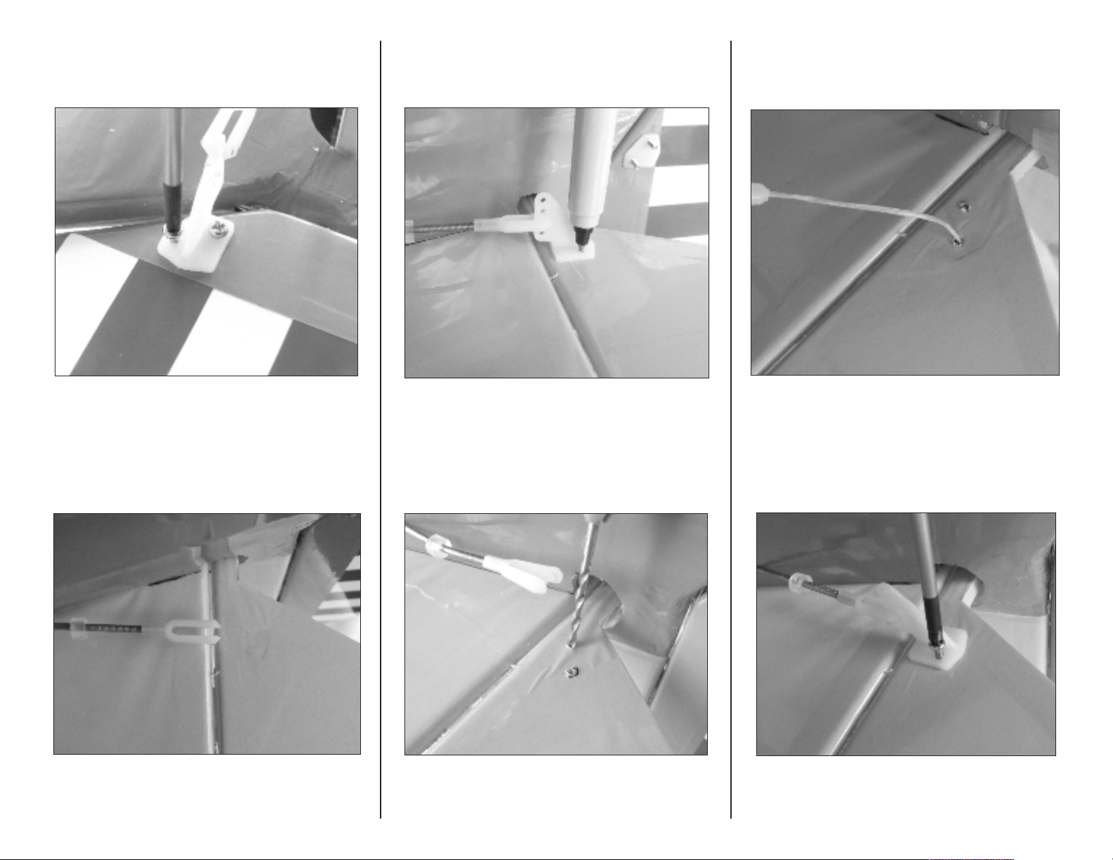
Ο 10. Install the rudder control horn and backing plate
with two 2mm x 10mm machine screws using a
#0 Philips screwdriver.
Ο 11. Place a silicone keeper on the elevator pushrod,
then thread on a clevis until the clevis pin is
aligned with the elevator hinge line.
Ο 14. Apply 1 - 2 drops of thin CA to each screw hole
to strengthen the wood and stop it crushing
when the horn is installed.
Ο 15. Install the elevator control horn and backing plate
with two 2mm x 10mm machine screws using a
#0 Philips screwdriver.
E-flite Stearman PT-17 15e ARF Assembly Manual
1
1
0
0
Ο 12. Connect a control horn to the clevis at the second
hole from the bottom and mark the screw holes on
the elevator with a felt-tipped pen.
Ο 13. Use a 1/16-inch drill bit in a pin vise to make the
holes for the control horn screws.
 Loading...