


Ultimate 20-300 10 ARF
Assembly Manual
|
Specifications |
Wingspan: |
38 in (960mm) |
Length: |
41 in (1045mm) |
Wing Area: |
473.5 sq in (30.5 sq dm) |
Weight w/o Battery: |
34–36 oz (965–1020 g) |
Weight w/Battery: |
39–41 oz (1105–1160 g) |

Table of Contents |
|
Introduction......................................................................... |
2 |
Using the Manual................................................................ |
2 |
Contents of Kit/Parts Layout.................................................. |
3 |
Covering Colors................................................................... |
3 |
Required Radio Equipment................................................... |
3 |
Required Tools and Adhesives............................................... |
4 |
Important Information About Motor Selection......................... |
4 |
Brushless Outrunner Setup.................................................... |
4 |
Optional Accessories............................................................ |
4 |
Notes Regarding Servos and ESC......................................... |
4 |
Note on Lithium Polymer Batteries......................................... |
4 |
Warning............................................................................. |
4 |
Warranty Information........................................................... |
5 |
Safety, Precautions, and Warnings........................................ |
7 |
Hinging the Ailerons............................................................ |
7 |
Aileron Servo Installation.................................................... |
10 |
Stabilizer Installation.......................................................... |
15 |
Hinging the Rudder and Stabilizer...................................... |
19 |
Rudder and Elevator Servo Installation................................ |
22 |
Receiver and Landing Gear Installation............................... |
24 |
Motor and Cowling Installation........................................... |
25 |
Upper Wing and Canopy Installation.................................. |
29 |
Control Throws.................................................................. |
32 |
Final Control Throws.......................................................... |
34 |
Center of Gravity............................................................... |
35 |
Preflight............................................................................. |
35 |
Range Test Your Radio........................................................ |
36 |
Flying Your Ultimate 20-300............................................... |
36 |
Instructions for Disposal of WEEE by |
|
Users in the European Union.................................... |
36 |
2008 Official AMA National Model Aircraft Safety Code.... |
37 |
Building and Flying Notes.................................................. |
38 |
2
Introduction
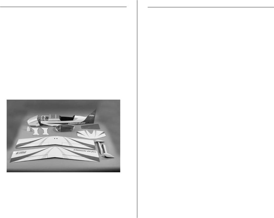
E-flite's Ultimate 20-300 10 ARF is a sport replica of the rare two-place aerobatic aircraft. The large wing area and light wing loading of its biplane design provide smooth flight characteristics and precise response. The Ultimate is designed around E-flite's Power 10, which provides excellent power for any aerobatic maneuver. The Ultimate's features include: UltraCote® and UltraCote Lite covering, steerable tail wheel, authentic Ultimate style spinner, fiberglass cowl and wheel
pants, plastic molded wing fillets, and a lightweight balsa and plywood frame. The features and level of prefabrication of the Ultimate allows the modelers to have the ability to fly this incredible biplane in less time than similar models.
Intermediate pilots will enjoy the ability to grow their skills rapidly with the Ultimate, while advanced pilots will enjoy maximum performance with no extra effort.
Using the Manual
This manual is divided into sections to help make assembly easier to understand, and to provide breaks between each major section. In addition, check boxes have been placed next to each step to keep track of each step completed. Steps with a single circle () are performed once, while steps with two circles ( ) indicate that the step will require repeating, such as for a right or left wing panel, two servos, etc.
Remember to take your time and follow the directions.
E-flite Ultimate 20-300 Assembly Manual
Contents of Kit/Parts Layout
Replacement Parts
EFL2751 |
Fuselage |
|
EFL2752 |
Top Wing w/Ailerons, Left and Right |
|
EFL2753 |
Bottom Wing w/Ailerons, Left and Right |
|
EFL2754 |
Tail Set |
|
EFL2755 |
Outer Wing Struts |
|
EFL2756 |
Cowl |
|
EFL2757 |
Canopy |
|
EFL2758 |
Spinner |
|
EFL2759 |
Landing Gear |
|
EFL2760 |
Wheel Pants |
|
EFL2761 |
Axles |
|
EFL2762 |
Wheels |
|
EFL2763 |
Hardware Set |
|
EFL2764 |
Pushrod Set |
|
|
|
|
|
|
|
|
|
Covering Colors |
Scale White |
HANU973 |
|
Deep Blue |
HANU873 |
|
Silver |
HANU881 |
|
Bright Yellow |
HANU872 |
|
E-flite Ultimate 20-300 Assembly Manual
Required Radio Equipment
You will need a minimum 5-channel transmitter, receiver, and four sub-micro servos. You can choose to purchase a complete radio system. If you are using an existing transmitter, just purchase
the other required equipment separately. We recommend the crystal-free, interference-free Spektrum™ DX6i 2.4GHz DSM® 6-channel system. If using your own transmitter, we recommend the Spektrum 7.5-gram Super Sub-Micro Digital Programmable Servos. When using the Spectrum DS75 servos with the Ultimate 20-300 you must use the Spectrum Digital Servo Programmer (SPMDSP). This will allow you to get the proper travel, resolution and geometry.
If you own the Spektrum DX6i radio, just add the AR6200 DSM2™ 6-channel receiver and four of our Spektrum 7.5-gram Super Sub-Micro Digital Programmable Servos.
Complete Radio System |
|
SPM6600 |
DX6i DSM 6CH system |
Or Purchase Separately |
|
SPMAR6200 |
AR6200 DSM2 6-Channel Receiver Ultralite |
|
(for DX6i or DX7) |
And |
|
SPMDSP |
Spektrum Digital Servo Programmer |
SPMDSP75 |
7.5-gram Super Sub-Micro Digital |
|
Programmable Servo (4) |
EFLREX3L |
3-inch Extension, Lightweight |
EFLREX6L |
6-inch Extension, Lightweight (4) |
EFLREX9L |
9-inch Extension, Lightweight |
EFLREX12L |
12-inch Extension, Lightweight |
3

Required Tools and Adhesives
Tools & Equipment |
|
Felt-tipped pen |
Ball driver: 3/32-inch |
Low-tack masking tape |
Mixing sticks |
Paper towels |
Pin drill |
Rubbing alcohol |
Mixing cups |
Drill bits: 1/16-inch (1.5mm) |
Hobby knife (#11 blade) |
Phillips screwdriver: #0, #1 |
Straight edge/Ruler |
Side cutters |
Adjustable wrench, small |
Sandpaper |
Scissors |
Adhesives |
|
Thin CA |
Medium CA |
Threadlock |
6-minute Epoxy (HAN8000) |
Canopy glue |
|
Important Information About
Motor Selection
We recommend the E-flite Power 10 Brushless Outrunner Motor, 1100Kv (EFLM4010A) for maximum performance.
Brushless Outrunner Setup
EFLM4010A |
Power 10 Brushless Outrunner Motor |
|
1100Kv |
EFLA1040 |
40-Amp Pro Switch-Mode BEC Brushless |
EFLB21003S |
E-flite 3S 11.1V 2100mAh 20C Li-Po or |
|
Thunder Power 3S 11.1V 2200mAh 25C |
|
eXtreme V2 Li-Po (THP22003SXV) |
EFLAEC311 |
EC3 Extension Lead w/6" Wire, 16GA |
APC12060E |
12x6 Electric Propeller |
|
|
Optional Accessories |
|
EFLA110 |
Power Meter |
||
EFLC3005 |
Celectra™ 1- to 3-Cell Li-Po Charger |
||
EFLC505 |
Intelligent 1- to 5-Cell Balancing Charger |
||
4
Notes Regarding Servos and ESC
WARNING: Use of servos other than those we suggest may overload the BEC of the recommended Electronic Speed Control (ESC). Please use only the servos listed when utilizing the recommended ESC’s BEC, or the use of a separate BEC (like the UBEC) or receiver battery pack when using other servos.
Note on Lithium Polymer Batteries
Lithium Polymer batteries are significantly more volatile than alkaline or Ni-Cd/Ni-MH batteries used in RC applications. All manufacturer’s instructions and warnings must be followed closely. Mishandling of Li-Po batteries can result in fire. Always follow the manufacturer’s instructions when disposing of Lithium Polymer batteries.
Warning
An RC aircraft is not a toy! If misused, it can cause serious bodily harm and damage to property. Fly only in open areas, preferably at AMA (Academy of Model Aeronautics) approved flying sites, following all instructions included with your radio.
Keep loose items that can get entangled in the propeller away from the prop, including loose clothing, or other objects such as pencils and screwdrivers. Especially keep your hands away from the propeller.
E-flite Ultimate 20-300 Assembly Manual

Warranty Information
Warranty Period
Horizon Hobby, Inc., (Horizon) warranties that the Products purchased (the “Product”) will be free from defects in materials and workmanship at the date of purchase by the Purchaser.
Limited Warranty
(a)This warranty is limited to the original Purchaser ("Purchaser") and is not transferable. REPAIR OR REPLACEMENT AS PROVIDED UNDER THIS WARRANTY IS THE EXCLUSIVE REMEDY OF THE PURCHASER.
This warranty covers only those Products purchased from an authorized Horizon dealer. Third party transactions are not covered by this warranty. Proof of purchase is required for warranty claims. Further, Horizon reserves the right to change or modify this warranty without notice and disclaims all other warranties, express or implied.
(b)LimitationsHORIZON MAKES NO WARRANTY OR REPRESENTATION, EXPRESS OR IMPLIED, ABOUT NONINFRINGEMENT, MERCHANTABILITY OR FITNESS FOR A PARTICULAR PURPOSE OF THE PRODUCT. THE PURCHASER ACKNOWLEDGES THAT THEY ALONE HAVE DETERMINED THAT THE PRODUCT WILL SUITABLY MEET THE REQUIREMENTS OF THE PURCHASER’S INTENDED USE.
(c)Purchaser RemedyHorizon's sole obligation hereunder
shall be that Horizon will, at its option, (i) repair or (ii) replace, any Product determined by Horizon to be defective. In the event of a defect, these are the Purchaser's exclusive remedies. Horizon reserves the right to inspect any and all equipment involved in a warranty claim. Repair or replacement decisions are at the sole discretion of Horizon. This warranty does not cover cosmetic damage or damage due to acts of God, accident, misuse, abuse, negligence, commercial use, or modification of or to any part of the Product. This warranty does not cover damage due to improper installation, operation, maintenance, or attempted repair by anyone other than Horizon. Return of any goods by Purchaser must be approved in writing by Horizon before shipment.
E-flite Ultimate 20-300 Assembly Manual
Damage Limits
HORIZON SHALL NOT BE LIABLE FOR SPECIAL, INDIRECT OR CONSEQUENTIAL DAMAGES, LOSS OF PROFITS OR PRODUCTION OR COMMERCIAL LOSS IN ANY WAY CONNECTED WITH THE PRODUCT, WHETHER SUCH CLAIM IS BASED IN CONTRACT, WARRANTY, NEGLIGENCE, OR STRICT LIABILITY. Further, in no event shall the liability of Horizon exceed the individual price of the Product on which liability is asserted. As Horizon has no control over use, setup, final assembly, modification or misuse, no liability shall be assumed nor accepted for any resulting damage or injury. By the act of use, setup or assembly, the user accepts all resulting liability.
If you as the Purchaser or user are not prepared to accept the liability associated with the use of this Product, you are advised to return this Product immediately in new and unused condition to the place of purchase.
Law: These Terms are governed by Illinois law (without regard to conflict of law principals).
Safety Precautions
This is a sophisticated hobby Product and not a toy. It must be operated with caution and common sense and requires some basic mechanical ability. Failure to operate this Product in a safe and responsible manner could result in injury or damage to the Product or other property. This Product is not intended for use by children without direct adult supervision. The Product manual contains instructions for safety, operation and maintenance. It is essential to read and follow all the instructions and warnings in the manual, prior to assembly, setup or use, in order to operate correctly and avoid damage or injury.
5

Questions,Assistance, and Repairs
Your local hobby store and/or place of purchase cannot provide warranty support or repair. Once assembly, setup or use of the Product has been started, you must contact Horizon directly. This will enable Horizon to better answer your questions and service you in the event that you may need any assistance. For questions or assistance, please direct your email to productsupport@horizonhobby.com, or call 877.504.0233 toll free to speak to a service technician.
Inspection or Repairs
If this Product needs to be inspected or repaired, please call for a Return Merchandise Authorization (RMA). Pack the Product securely using a shipping carton. Please note that original boxes may be included, but are not designed to withstand the rigors of shipping
without additional protection. Ship via a carrier that provides tracking and insurance for lost or damaged parcels, as Horizon is not responsible for merchandise until it arrives and is accepted
at our facility. A Service Repair Request is available at www. horizonhobby.com on the “Support” tab. If you do not have internet access, please include a letter with your complete name, street address, email address and phone number where you can be reached during business days, your RMA number, a list of the included items, method of payment for any non-warranty expenses and a brief summary of the problem. Your original sales receipt must also be included for warranty consideration. Be sure your name, address, and RMA number are clearly written on the outside of the shipping carton.
Warranty Inspection and Repairs
To receive warranty service, you must include your original sales receipt verifying the proof-of-purchase date. Provided warranty
conditions have been met, your Product will be repaired or replaced free of charge. Repair or replacement decisions are at the sole discretion of Horizon Hobby.
6
Non-Warranty Repairs
Should your repair not be covered by warranty the repair will be completed and payment will be required without notification or estimate of the expense unless the expense exceeds 50% of the retail purchase cost. By submitting the
item for repair you are agreeing to payment of the repair without notification. Repair estimates are available upon request. You must include this request with your repair. Non-warranty repair estimates will be billed a minimum of ½ hour of labor. In addition you will be billed for return freight. Please advise us of your preferred method of payment. Horizon accepts money orders and cashiers checks, as well as Visa, MasterCard, American Express, and Discover cards. If you choose to pay by credit card, please include your credit card number and expiration date. Any repair left unpaid or unclaimed
after 90 days will be considered abandoned and will be disposed of accordingly. Please note: non-warranty repair is only available on electronics and model engines.
Electronics and engines requiring inspection or repair should be shipped to the following address:
Horizon Service Center
4105 Fieldstone Road
Champaign, Illinois 61822 or
Horizon Hobby UK
Units 1-4, Ployters Road
Staple Tye - Southern Way
Harlow
Essex
CM187NS
United Kingdom
All other Products requiring warranty inspection or repair should be shipped to the following address:
Horizon Product Support
4105 Fieldstone Road
Champaign, Illinois 61822
Please call 877-504-0233 or visit horizonhobby.com to find our distributor for your country for support with any questions or concerns regarding this product or warranty.
E-flite Ultimate 20-300 Assembly Manual

Safety, Precautions, and Warnings
As the user of this product, you are solely responsible for operating it in a manner that does not endanger yourself and others or result in damage to the product or the property of others.
Carefully follow the directions and warnings for this and any optional support equipment (chargers, rechargeable battery packs, etc.) that you use.
This model is controlled by a radio signal that is subject to interference from many sources outside your control. This interference can cause momentary loss of control so it is necessary to always keep a safe distance in all directions around your model, as this margin will help to avoid collisions or injury.
•Always operate your model in an open area away from cars, traffic or people.
•Avoid operating your model in the street where injury or damage can occur.
•Never operate the model out into the street or populated areas for any reason.
•Never operate your model with low transmitter batteries.
•Carefully follow the directions and warnings for this and any optional support equipment (chargers, rechargeable battery packs, etc.) that you use.
•Keep all chemicals, small parts and anything electrical out of the reach of children.
•Moisture causes damage to electronics. Avoid water exposure to all equipment not specifically designed and protected for this purpose.
E-flite Ultimate 20-300 Assembly Manual
|
Hinging the Ailerons |
Required Parts |
|
Top wing |
Top ailerons (right and left) |
Bottom wing |
Bottom ailerons (right and left) |
CA hinge (16) |
|
Required Tools and Adhesives |
|
Felt-tipped pen |
Straight edge/ruler |
Hobby knife |
Thin CA |
Scissors |
|
1. Use scissors or a hobby knife to cut each hinge away from the others.
mmm 2. Use a felt-tipped pen to mark the center of four CA hinges. This will help in positioning them equally in the aileron and wing.
7
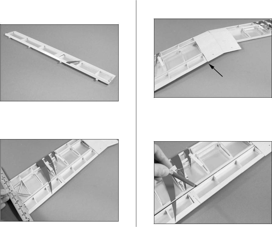
mmm 3. Position the hinges in the pre-cut slots in the aileron. Slide the hinges into the aileron up to the mark made in the previous step.
mmm 4. Slide the aileron in position with the hinges inserted in the slots of the wing. Check that the end of the aileron is aligned with the wing tip using a straight edge.
8
mmm 5. Make sure the aileron does not bind at the center of the wing.
mmm 6. Use a hobby knife with a #11 blade to set the gap between the aileron and wing. The blade should barely slide between the two surfaces. Doing so will allow achieving the control throws listed with the smallest gap possible.
E-flite Ultimate 20-300 Assembly Manual

Note: If the control surface is tight against the main surface, it will limit the amount of control throw the surface can achieve.
mmm 7. Apply thin CA to the top and bottom of each hinge. Make sure to saturate the hinges, applying the CA to the slot in the hinge so it penetrates fully into the hinge for the best bond between the aileron and wing.
m 8. Repeat Steps 2 through 7 for the remaining aileron on the bottom wing.
E-flite Ultimate 20-300 Assembly Manual
9. Repeat Steps 2 through 8 to attach the aileron to the top wing. You should now be done with the aileron installation.
10. Once the CA has fully cured, lightly pull on each surface to make sure that each hinge has been fully saturated with CA.
9
Aileron Servo Installation
Required Parts |
|
Top wing |
Bottom wing |
Control horn (2) |
Interconnect horn (4) |
Aileron servo (2) |
Silicone clevis retainer (2) |
Nylon connector backplate (2) |
Machine screw, 2mm x 4mm (2) |
6-inch (152mm) servo extension (2) |
|
Lightweight screw lock connector (2) |
|
Servo linkage, 2.5-inch (62mm) (2) |
|
Required Tools and Adhesives |
|
Medium CA |
Thin CA |
Side cutters |
Hobby knife |
Low-tack tape |
Pin drill |
Drill bit: 1/16-inch (1.5mm) |
Phillips screwdriver: #0, #1 |
Felt-tipped pen |
|
10
mmm 1. Slide the control horn into the pre-drilled holes in the aileron. Use a felt-tipped pen to mark the area around the base of the control horn. Remove the horn and use a hobby knife to cut the covering away from the area inside the outline. Use side cutters to trim 2-3mm off of the aft lug on the control horn. This will eliminate the lug protruding through the other side of the aileron. Use medium CA to glue the control horn in the holes in the aileron. Make sure the horn rests flush with the surface of the aileron.
Note: The aileron control horns do not require back plates.
E-flite Ultimate 20-300 Assembly Manual
mmm 2. Use a hobby knife to trim the covering from the slot in the aileron. Leave the covering on the top for aesthetic purposes. Use medium CA to glue the
interconnect horn in the aileron. Make sure to center the horn in the aileron before the CA fully cures.
Align horn to aileron centerline
m 3. Repeat Step 2 for the top aileron at this time.
E-flite Ultimate 20-300 Assembly Manual
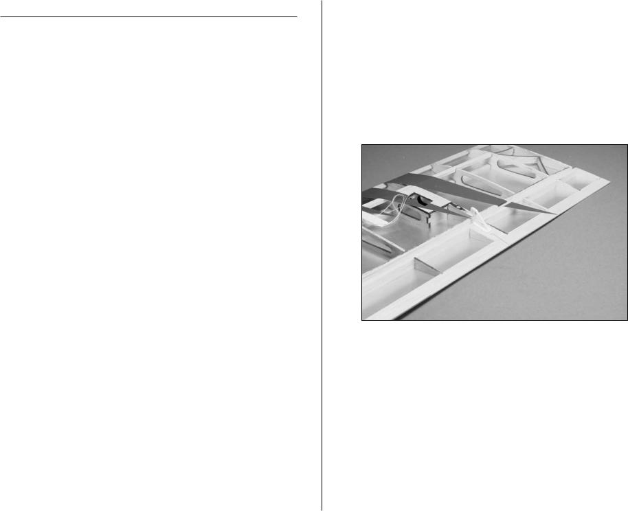
m 4. Secure a 6-inch (152mm) servo extension to the aileron servo so it will not unplug inside the wing.
Hint: Use a piece of string or some tape to secure the two plugs together so that they cannot pull apart inside the wing.
m 5. A string has been placed inside the wing to pull the servo extension to the center of the wing. Tie this string to the end of the servo extension as shown.
11

m 6. Use the string to pull the extension through the hole at the center of the bottom wing.
Hint: Use low-tack tape to keep the ailerons from moving during the servo installation.
12
m 7. Position the servo in the opening. Use a pin drill and 1/16-inch (1.5mm) drill bit to drill the holes for the servo mounting screws. Use care not to slip and puncture the covering on the top of the wing.
m 8. Apply 2–3 drops of thin CA into each hole to harden the surrounding wood. This will keep the screws secure in the holes. Install the servo using the screws provided with the servo and a #0 Phillips screwdriver.
E-flite Ultimate 20-300 Assembly Manual
 Loading...