


F-86 Sabre 15 DF
Assembly Manual
|
|
Specifications |
Wingspan: |
33.8 in (860mm) |
|
Length: |
35.4 in (900mm) |
|
Wing Area: |
256 sq in (16.5 sq dm) |
|
Weight w/o Battery: |
40–42 oz (1135–1190 g) |
|
Weight w/Battery: |
53–55 oz (1500–1560 g) |
|
Pilot not included (PKZ7003)
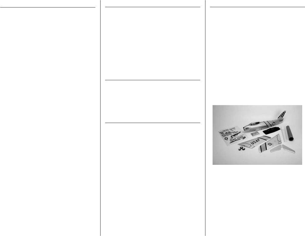
Table of Contents |
|
Introduction............................................................ |
2 |
Important Information Regarding |
|
Warranty Information........................................ |
2 |
Using the Manual................................................... |
2 |
Contents of Kit/Parts Layout.................................... |
2 |
Recommended Radio Equipment.............................. |
3 |
Required Brushless Ducted Fan Setup....................... |
3 |
Required Tools and Adhesives.................................. |
3 |
Optional Accessories.............................................. |
3 |
Warnings............................................................... |
3 |
Aileron Servo Installation........................................ |
4 |
Aileron Linkage Installation...................................... |
6 |
Mounting the Main Wing Panels.............................. |
9 |
Stabilizer Installation............................................. |
12 |
Elevator Installation............................................... |
15 |
Rudder Installation................................................ |
16 |
Elevator Servo and Linkage Installation.................. |
18 |
Rudder Servo and Linkage Installation.................... |
22 |
Landing Gear Installation...................................... |
24 |
Steering Servo and Linkage Installation.................. |
26 |
Speed Control and Receiver Installation.................. |
27 |
Intake Tube Installation.......................................... |
29 |
Fan Installation..................................................... |
30 |
Exhaust Tube Installation........................................ |
32 |
Securing the Intake Tube........................................ |
34 |
Canopy Assembly................................................. |
35 |
Motor Battery Installation....................................... |
35 |
Decal Placement................................................... |
36 |
Center of Gravity.................................................. |
36 |
Control Throws..................................................... |
37 |
Preflight............................................................... |
38 |
Flying Your F-86 Sabre 15 DF............................... |
38 |
Range Test Your Radio........................................... |
38 |
Safety Do’s and Don’ts for Pilots............................. |
39 |
Daily Flight Checks............................................... |
39 |
Warranty and Repair Policy.................................. |
39 |
Warranty Services................................................ |
40 |
Compliance Information for the European Union..... |
41 |
2010 Official Academy of |
|
Model Aeronautics Safety Code........................ |
41 |
2
Introduction
This performance model was designed around E-flite’s Delta-V 15 (69mm) fan unit and matched 15 DF 3200Kv brushless motor. Pilots can use a 4-cell Li-Po battery pack for great performance. The built-in fan mounts make installing the fan easy—just drop in
the fan unit and tighten four screws. The removable magnetic front hatch also allows easy access to the radio equipment and battery. The entire trim scheme is prepainted, pre-trimmed; the wings are covered in UltraCote®. Just add your favorite nose art decals and enjoy.
Important Information
Regarding Warranty Information
Please read our Warranty and Liability Limitations section on Page 39 before building this product. If you as the Purchaser or user are not prepared to accept the liability associated with the use of this Product, you are advised to return this Product immediately in new and unused condition to the place of purchase.
Using the Manual
This manual is divided into sections to help make assembly easier to understand, and to provide breaks between each major section. In addition, check boxes have been placed next to each step to keep track
of its completion. Steps with a single circle () are performed once, while steps with two circles ( ) indicate the step will require repeating, such as for a right or left wing panel, two servos, etc.
Remember to take your time and follow the directions.
Contents of Kit/Parts Layout
Replacement Parts |
|
|
|
EFL8101 |
Fuselage with Upper and |
|
|
Lower Hatch |
|
EFL8102 |
Canopy Hatch |
|
EFL8103 |
Left Wing Panel with |
|
|
Hinged Aileron |
|
EFL8104 |
Right Wing Panel with |
|
|
Hinged Aileron |
|
EFL8105 |
Horizontal Stabilizer with |
|
|
Elevator (left and right) |
|
EFL8106 |
Pushrods and Carbon |
|
|
Wing Tubes |
|
EFL8107 |
Plastic Accessories |
|
EFL8108 |
Landing Gear and Wheels |
|
|
with Hardware |
|
EFL8109 |
Control Hardware |
|
EFL8110 |
Intake and Thrust Tube |
|
EFL8111 |
Consumer Decal Sheet |
|
|
|
|
|
|
E-flite F-86 Sabre 15 DF ARF Assembly Manual

Recommended Radio Equipment
You will need a minimum 4-channel transmitter, receiver and five servos. You can choose to purchase a complete radio system. If you are using an existing transmitter, just purchase the other required equipment separately. We recommend the crystal-
free, interference-free Spektrum™ DX6i 2.4GHz DSM® 6-channel system. If using your own transmitter, we recommend the following radio equipment.
If you own the Spektrum DX6i radio, or you are using a different DSM2 radio, just add the AR6200 DSM2™ 6-channel receiver, four E-flite S75 Sub-Micro servos and one JR SPORT™ MC35 servo
Complete Radio System
SPM6600 |
DX6i DSM2 6CH system |
Or Purchase Separately |
|
SPMAR6200 |
AR6200 DSM2 6-Channel Full- |
|
Range Receiver (for DX6i or |
|
DX7) |
EFLRS75 |
7.5-Gram Sub-Micro S75 |
|
Servo (4) |
JSP20030 |
MC35 Micro Servo |
And |
|
EFLREX9L |
9-inch Extension, Lightweight (2) |
Note: A Y-harness can be used for the for nose gear steering if a computer radio with mixing is not being used.
EFLRYH3 3-inch Y-Harness, Lightweight
Required Brushless Ducted Fan Setup
EFLM3215DF |
15 DF Brushless Motor, 3200Kv |
EFLDF15 |
Delta-V 15 (69mmm) Ducted |
|
Fan Unit |
EFLA1060 |
60-Amp Pro Switch-Mode |
|
BEC Brushless ESC |
EFLB32004S30 |
3200mAh 4S 14.8V 30C Li-Po, |
|
13AWG EC3 |
The Spektrum trademark is used with permission of Bachmann Industries, Inc.
E-flite F-86 Sabre 15 DF ARF Assembly Manual
Required Tools and Adhesives
Tools & Equipment |
|
Epoxy brushes |
Felt-tipped pen |
Hobby scissors |
Hobby knife (#11 blade) |
Low-tack tape |
Hex wrench: 1.5mm |
Mixing cups |
Sanding bar |
Mixing sticks |
Needle-nose pliers |
Paper towels |
Pencil |
Petroleum jelly |
Phillips screwdriver: #0, #1 |
Pin vise |
Rubbing alcohol |
Ruler |
Scissors |
Side cutters |
Square |
String/dental floss |
Toothpicks |
T-pins |
Waxed paper |
Sandpaper |
|
Drill bit: 1/16-inch (1.5mm), 5/64-inch (2mm) |
|
Adhesives |
|
Threadlock |
6-Minute Epoxy (HAN8000) |
Thin CA |
12-Minute Epoxy (HAN8001) |
Medium CA |
|
Optional Accessories
PKZ7003 |
Pilot: Habu |
EFLA110 |
Power Meter |
EFLC505 |
Intelligent 1- to 5-Cell |
|
Balancing Charger |
EFLAEC312 |
Charge Lead with 12-inch |
|
wire and Jacks, 16AWG |
 Warnings
Read and follow all instructions and safety precautions before use. Improper use can result in fire, serious injury and damage to property.
Components
Use only with compatible components. Should any compatibility questions exist please refer to the product instructions, the component instructions or contact Horizon Hobby, Inc.
Flight
Fly only in open areas to ensure safety. It is recommended flying be done at AMA (Academy of Model Aeronautics) approved flying sites.
Propeller
Keep loose items that can get entangled in the propeller away from the prop, including loose clothing, or other objects such as pencils and screwdrivers. Especially keep your hands away from the propeller as injury can occur.
Batteries
 Notes on Lithium Polymer Batteries
Lithium Polymer batteries are significantly more volatile than alkaline or Ni-Cd/Ni-MH batteries used in RC applications. Always follow the manufacturer’s instructions when using and disposing of any batteries. Mishandling of Li-Po batteries can result in fire and explosion causing serious injury and damage.
3
Small Parts
This kit includes small parts and should not be left unattended near children as choking and serious injury could result.
Safety Precautions
This is a sophisticated hobby Product and not a toy. It must be operated with caution and common sense and requires some basic mechanical ability. Failure to
operate this Product in a safe and responsible manner could result in injury or damage to the Product or other property. This Product is not intended for use by children without direct adult supervision. The Product manual contains instructions for safety, operation and maintenance. It is essential to read and follow all
the instructions and warnings in the manual, prior to assembly, setup or use, in order to operate correctly and avoid damage or injury.
During the course of building your F-86 Sabre we suggest you use a soft base for the building surface. Such things as a foam stand, large piece of bedding foam or a thick bath towel will work well and help protect the model from damage during assembly.
4
Aileron Servo Installation
Required Parts |
|
Left wing panel |
Right wing panel |
Transmitter |
Receiver |
Servo (2) |
|
2.5 x 12mm sheet metal screw (4)
9-inch (228mm) extension (2) Aileron servo mount (2) Servo mounting strap (2)
Required Tools and Adhesives
Medium grit sandpaper
6-minute epoxy |
Phillips screwdriver: #1 |
Dental floss/string |
Hobby knife with #11 blade |
Side cutter |
Ruler |
Pen |
Mixing cups |
Mixing sticks |
Paper towels |
The wood servo cover will not be used when installing the recommended E-flite S75 servo for the ailerons. If you install a smaller servo, you may choose to use the plywood cover rather than the molded plastic cover.
1. Remove the wood servo cover from the wing. Set the cover aside.
2. Relocate the string from the aileron opening so it is near one of the corners. This allows full access to the opening and prevents accidentally gluing the string into the wing.
DO NOT remove the string from the wing. The string will be used to pull the aileron servo lead through the wing later in this section.
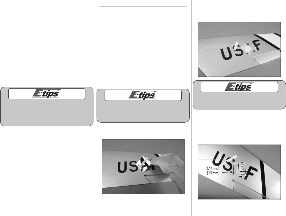
3. Measure and mark the opening for the aileron servo 3/4-inch (19mm) from the edge closest to the wing root as shown. The edge of the aileron servo mount will align with these marks when it is installed. Center the mount fore/aft in the opening for the aileron servo.
E-flite F-86 Sabre 15 DF ARF Assembly Manual
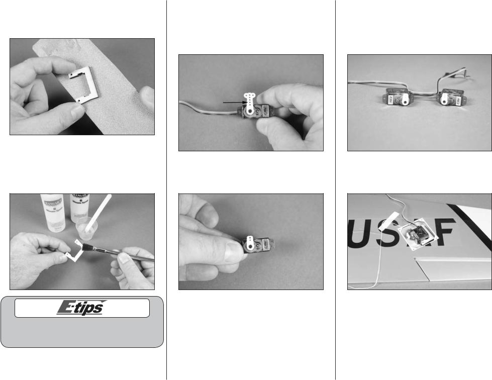
4. Lightly sand the aileron servo mount using medium grit sandpaper. This allows the glue to penetrate into the mount and provides a better bond between the mount and wing.
5. Mix a small amount of 6-minute epoxy and brush it onto the side of the aileron servo mount that was sanded in the previous step. Position the mount in the wing as shown in Step 3 and allow the epoxy to fully cure before proceeding.
While waiting for the epoxy to dry on one wing panel, you can repeat the previous steps to glue the remaining servo mount into the opposite wing panel.
E-flite F-86 Sabre 15 DF ARF Assembly Manual
6. Use a hobby knife with a #11 blade to enlarge the hole in the servo arm indicated in the photo. Only open the hole in the servo arm enough for the aileron linkage to fit in. Making it larger will only create a poor fit between the linkage and servo arm and make it difficult to trim your aircraft.
7. Use a hobby knife and #11 blade or side cutters to remove the excess servo arm so it does not interfere with the servo cover when it is installed.
8. Prepare a second aileron servo as shown in Steps 6 and 7. Note the servos will be a mirror image of each other. Plug the aileron servos into the receiver and use the transmitter to center the servos. Also check that they are operating correctly at this time.
9. Position the aileron servo in the servo mount as shown in the image with the horn facing the front of the wing.
5
10. Use a #1 Phillips screwdriver and two 2.5mm x 12 sheet metal screws to secure the servo in the servo mount using the servo mounting strap. Install one screw and only turn it one or two turns, then install the second screw. Tighten the strap with even pressure at both the front and back of the servo.
Use care when installing the servo mounting strap. Over-tightening the strap could stress the wing sheeting and even push the servo through the top of the wing.
11. Use string or dental floss to secure a 9-inch (228mm) servo extension to the lead from the aileron servo.
6
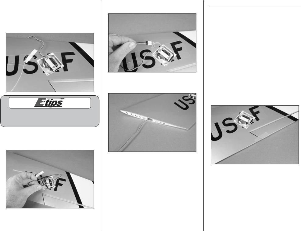
12. Tie the string around the end of the servo lead as shown.
13. Carefully pull the aileron servo lead through the wing using the string tied to it in the previous step.
14. Repeat Steps 1 through 13 to install the remaining aileron servo.
Aileron Linkage Installation
Required Parts
Transmitter Receiver Aileron pushrod keeper (2)
Aileron pushrod wire, 2 9/16-inch (65mm) (2) Servo cover (2)
Aileron control horn (2) |
Clear tape |
|
Required Tools and Adhesives |
|
|
Side cutters |
Medium CA |
|
Pin vise |
Low-tack tape |
|
Felt-tipped pen |
Hobby knife with #11 blade |
|
Needle-nose pliers |
Hobby scissors |
|
Drill bit: 1/16-inch (1.5mm), 5/64-inch (2mm)
1. Use a small piece of low-tack tape to keep the aileron centered with the trailing edge of the
wing. This will make the installation of the linkage much easier.
E-flite F-86 Sabre 15 DF ARF Assembly Manual
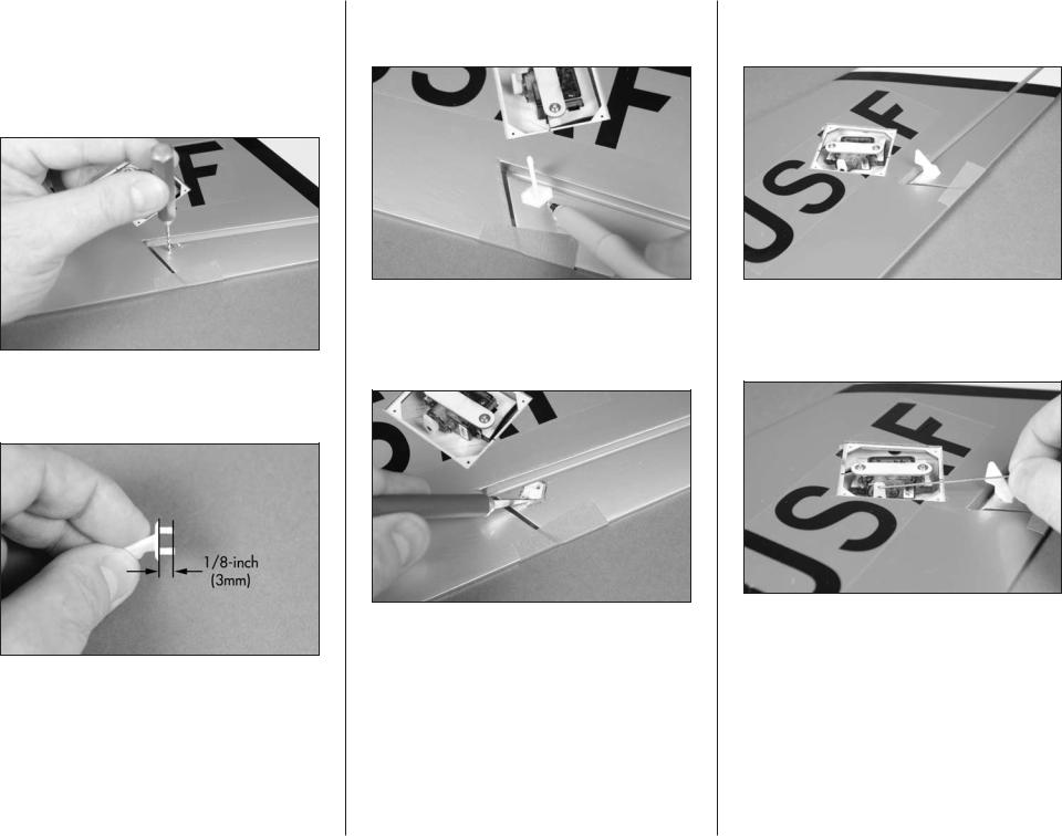
2. Locate the two holes for the aileron control horn in the aileron. The holes should be located directly behind the servo arm. Use a hobby knife with a #11 blade or pin vise with a 1/16-inch (1.5mm) drill bit to remove the covering for the aileron control horn. Use care not to accidentally make holes through to the top of the aileron.
3. Use side cutters to trim the pins on the control horn to a length of 1/8-inch (3mm) so they don’t extend through the top of the aileron.
E-flite F-86 Sabre 15 DF ARF Assembly Manual
4. Insert the pins of the control horn into the holes in the aileron. Use a felt-tipped pen to trace the outline of the control horn onto the aileron.
5. Remove the control horn. Use a hobby knife with a #11 blade to trim the covering 1/32-inch (1mm) inside the lines drawn. Don’t cut into the underlying wood as you could possibly weaken the structure.
6. Use medium CA to glue the control horn to the aileron. Allow the CA to cure before proceeding to the next step.
7. Connect the Z-bend of the 2 9/16-inch (65mm) aileron pushrod wire to the hole in the servo horn as shown.
7
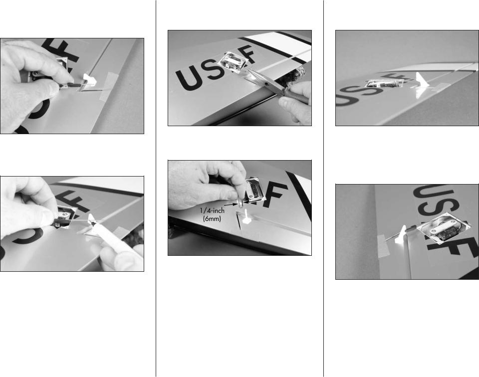
8. Slide the pushrod connector onto the pushrod wire at this time. The connector can’t be installed after the wire has been bent to fit into the control horn so it must be positioned at this time.
9. With the aileron servo centered and the radio system on, use a felt-tipped pen to mark the wire where it crosses the hole of the control horn as shown.
8
10. Use pliers to make a 90-degree bend in the pushrod wire. The bend must be angled to fit into the control horn.
11. Use side cutters to trim the wire 1/4-inch (6mm) from the bend as shown.
12. Insert the pushrod wire into the hole of the control horn that is two holes up from the control surface as shown.
13. Use pliers to open the pushrod keeper just enough to slip it over the bend of the pushrod wire so it secures the pushrod wire to the control horn. Don’t open the connector too far as it could possibly break the connector.
E-flite F-86 Sabre 15 DF ARF Assembly Manual
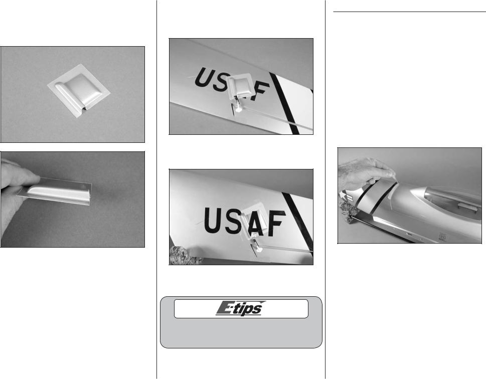
14. Use a hobby knife and #11 blade or hobby scissors to trim the aileron servo cover. Lines have been embossed on the cover to be used as a guide. Make sure the opening for the linkage is angled slightly so the linkage doesn’t bind on the cover.
E-flite F-86 Sabre 15 DF ARF Assembly Manual
15. Use the tape provided with the model to attach the cover to the wing. Make sure the aileron servo can operate without having the linkage binding on the cover.
16. Apply the decal to the servo cover. Take your time to fit the decal to the contours of the cover.
17. Repeat Steps 1 through 16 to install the remaining aileron linkage and servo cover.
Cut the portions of the letters from the decal sheet to apply to the cover to complete the form of the covered letters.
Mounting the Main Wing Panels
Required Parts
Left wing assembly Right wing assembly
Carbon wing rod, 9-inch (230mm)
Carbon wing rod, 13-inch (330mm)
Fuselage assembly
Required Tools and Adhesives
12-minute epoxy |
Mixing cup |
Mixing stick |
Epoxy brush |
Paper towel |
Rubbing alcohol |
Low-tack tape |
Sandpaper |
Sanding Bar |
|
1. Remove the shipping tape that holds the canopy to the fuselage.
9
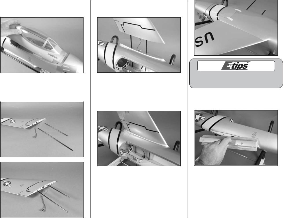
2. Carefully lift the canopy hatch from the fuselage. The canopy is held in position by magnets and alignment pegs at the rear and a peg at the front.
3. Slide the short and long wing rods into one of the wing panels. The longer wing rod will be
inserted near the trailing edge of the wing, and the shorter rod toward the leading edge of the wing.
10
4. Slide the wing tubes into the fuselage. Make sure to guide the aileron servo extension into the fuselage so the wing can fit tight against the fuselage.
5. Look at the fit of the wing to the fuselage on both the top and bottom. You will need to use sandpaper to remove the paint from the fuselage where the wing fits or the epoxy won’t hold the wing securely to the fuselage. You also don’t want to sand too much and ruin the paint on the fuselage.
You can use low-tack tape to make an outline about a 1/16-inch (1.5mm) inside the wing outline on the fuselage to prevent it from scratching the paint.
6. Remove the wing from the fuselage. Use medium grit sandpaper to remove the paint from the fuselage where the wing fits.
E-flite F-86 Sabre 15 DF ARF Assembly Manual
7. Repeat Steps 1 through 6 to prepare the opposite side of the fuselage for the wing.
8. Apply a thin layer of 15-minute epoxy to the fuselage where it was sanded previously.
9. Apply a thin layer of 15-minute epoxy to the short and long wing rods before you insert them into the wing.
E-flite F-86 Sabre 15 DF ARF Assembly Manual
10. Apply a thin coat of 15-minute epoxy on the end of the wing that will butt against the fuselage.
11. Slide the wing into position against the fuselage. Use low-tack tape to keep the wing tight against the fuselage until the epoxy fully cures.
12. Repeat Steps 8 through 11 to install the remaining wing panel to the fuselage.
13. Before the epoxy cures, use a paper towel and rubbing alcohol to remove any excess epoxy that may have oozed out from the joint between the wing and fuselage.
11
Stabilizer Installation
Required Parts |
|
Stabilizer jig center |
Stabilizer jig side (2) |
Right stabilizer |
Left stabilizer |
Airframe assembly |
|
Required Tools and Adhesives |
|
Medium CA |
Square |
6-minute epoxy |
Mixing cup |
Mixing stick |
Epoxy brush |
Paper towel |
Rubbing alcohol |
Low-tack tape |
Waxed paper |
Ruler |
Felt-tipped pen |
Hobby knife with #11 blade
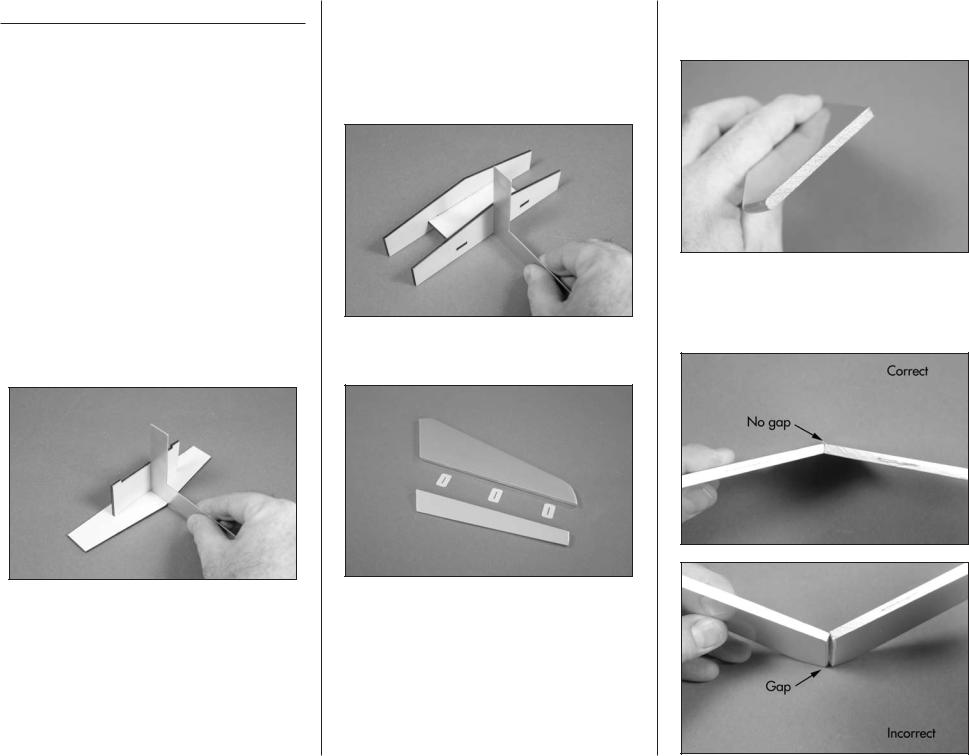
1. Use a square and medium CA to glue the stabilizer jig center to the stabilizer jig side. The square will keep the center perpendicular to the side and result in a straight jig. Not doing so may result in the jig being crooked and could produce the wrong angle when gluing the stabilizer halves together.
12
2. Use a square and medium CA to glue the stabilizer jig side to the structure assembled in Step 1. Using a square will keep the side perpendicular to the stabilizer jig center. Not
doing so may result in the jig being crooked and could produce the wrong angle when gluing the stabilizer halves together.
3. Separate the elevator from the stabilizer. Set the elevator and hinges aside at this time.
4. Use a hobby knife and a #11 blade to remove the covering from the end of both the left and right stabilizers.
5. The stabilizer halves have been prepared at the factory with an angle so they fit tightly together when joined. If the fit is incorrect, the two halves will not fit tightly together.
E-flite F-86 Sabre 15 DF ARF Assembly Manual
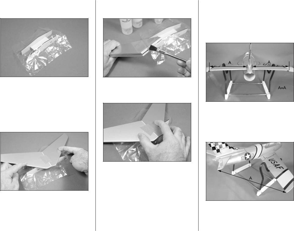
6. Place a piece of clear plastic or waxed paper over the stabilizer jig to prevent gluing the stabilizer directly to the jig.
7. Position the two stabilizer halves together (remember the angle) and align the front edges of the stabilizer halves. Use a small piece of lowtack tape to act as a hinge and keep the halves aligned. Position the stabilizer assembly on the jig to make sure the halves can rest against the jig without forcing them. If not, you will need to make a small gap between the two halves before taping them together.
E-flite F-86 Sabre 15 DF ARF Assembly Manual
8. Mix a small amount of 6-minute epoxy and use an epoxy brush to apply a thin layer of epoxy on the edges of each stabilizer half.
9. Position the stabilizer on the jig and either hold it or use weights to keep the halves tight against the jig until the epoxy fully cures.
10. Slide the stabilizer into the slot in the fuselage. Make sure that they are installed in the fuselage with dihedral as shown in Step 12. Measure the distance from the fuselage to the tip of the stabilizer on both sides of the fuselage. Both measurements must be equal. If they are not, reposition the stabilizer and re-measure until both measurements are equal on both sides of the fuselage.
11. Measure the distance from the wing tip to the stabilizer tip on both the right and left of the aircraft. Both measurements must be equal. If not, readjust the stabilizer and re-measure until the
measurement is the same on both the left and right of the aircraft.
13
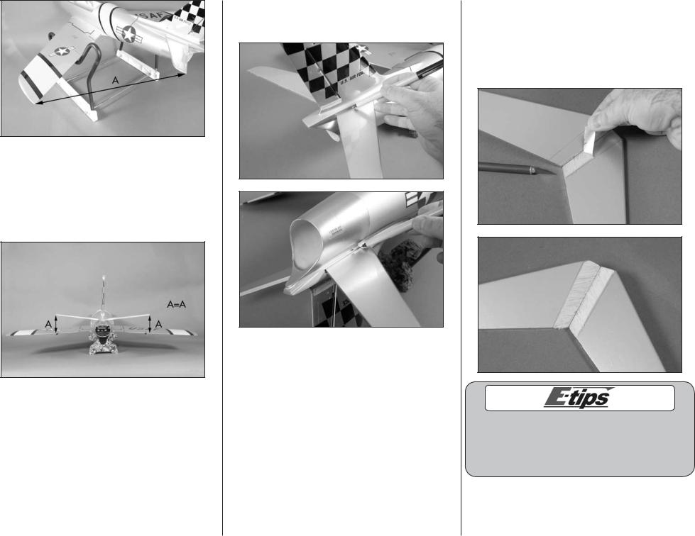
12. Step back about 4–5 feet (1.2–1.5 meters) and view the fuselage from the rear. Check that the stabilizer is in alignment with the wing by checking the stabilizer tips against the wing. Both stabilizer tips should align with the wing trailing edge. Adjust the position of the stabilizer if necessary for correct stabilizer alignment.
14
13. Use a felt-tipped pen to trace the outline of the fuselage onto the top, bottom, left and right of the stabilizer.
14. Remove the stabilizer from the fuselage. Carefully use a hobby knife to remove the covering 1/16-inch (1.5mm) from inside the lines. Use light pressure with a new #11 blade to avoid cutting into the underlying wood. You will need to trim the covering from the top and bottom of the stabilizer at this time.
Other options other than a hobby knife are to use a hot knife (with a new blade) or a soldering iron for cutting the covering. These will melt the covering and lower the chances of cutting into the wood structure of the stabilizer.
E-flite F-86 Sabre 15 DF ARF Assembly Manual
 Loading...