


Hurricane 25e
Assembly Manual
Montageanleitung Manuel d’assemblage Manuale di montaggio
TM


 ®
® 


EN
Notice
All instructions, warranties and other collateral documents are subject to change at the sole discretion of Horizon Hobby, Inc. For up-to-date product literature, visit http://www.horizonhobby. com and click on the support tab for this product.
Meaning of Special Language
The following terms are used throughout the product literature to indicate various levels of potential harm when operating this product:
NOTICE: Procedures, which if not properly followed, create a possibility of physical property damage AND a little or no possibility of injury.
CAUTION: Procedures, which if not properly followed, create the probability of physical property damage AND a possibility of serious injury.
WARNING: Procedures, which if not properly followed, create the probability of property damage, collateral damage, and serious injury OR create a high probability of superficial injury.
 WARNING: Read the ENTIRE instruction manual to become familiar with the features of the product before operating. Failure to operate the product correctly can result in damage to the product, personal property and cause serious injury.
2
This is a sophisticated hobby product. It must be operated with caution and common sense and requires some basic mechanical ability. Failure to operate this Product in a safe and responsible manner could result in injury or damage to the product or other property. This product is not intended for use by children without direct adult supervision. Do not attempt disassembly, use with incompatible components or augment product in any way without the approval of Horizon Hobby, Inc. This manual contains instructions for safety, operation and maintenance. It is essential to read and follow all the instructions and warnings in the manual, prior to assembly, setup or use, in order to operate correctly and avoid damage or serious injury.
Additional Safety Precautions and
Warnings
Age Recommendation: Not for children under 14 years. This is not a toy.
•Always keep a safe distance in all directions around your model to avoid collisions or injury. This model is controlled by a radio signal subject to interference from many sources outside your control. Interference can cause momentary loss of control.
•Always operate your model in open spaces away from full-size vehicles, traffic and people.
•Always carefully follow the directions and warnings for this and any optional support equipment (chargers, rechargeable battery packs, etc.).
•Always keep all chemicals, small parts and anything electrical out of the reach of children.
•Always avoid water exposure to all equipment not specifically designed and protected for this purpose. Moisture causes damage to electronics.
•Never place any portion of the model in your mouth as it could cause serious injury or even death.
•Never operate your model with low transmitter batteries.
Introduction
No fighter deserves more credit for saving Britain in its darkest hour than the Hawker Hurricane. It’s simple construction allowed it to be manufactured in large numbers and it could be quickly repaired in the field using basic tools. And, despite being
slower than the vaunted Spitfire, the Hurricane could out turn many of the enemy fighters it faced and bring its eight Browning machine guns to bear with devastating effect. This surprising maneuverability combined with its sheer numbers are two big reasons the humble Hurricane shot down more enemy aircraft in the Battle of Britain than any other Allied fighter.
Now you can experience the thrill of flying the
Hurricane in this remarkably scale rendition constructed of tough Z-Foam™ material. The Plug- N-Play® version comes out of the box with a highoutput brushless power system, digital metal-hybrid gear servos, and functional split flaps preinstalled. Even the authentic RAF No. 1 Squadron paint scheme and decals have been pre-applied. If
you choose the Bind-N-Fly® version, you get all of this plus a Spektrum™ AR600 DSMX receiver
preinstalled, as well as an E-flite 3S 3200 mAh 30C Li-Po battery and Li-Po charger.
All that is left to complete is a few minutes of final assembly. You also get the option of installing E-flite® 15-25 Electric Retracts (EFLG200sold separately). Installation is simple, and when you’re done, you will have a unique, scale warbird that will be the envy of the flying field!
|
Specifications |
|
|
Wingspan: |
53.5 in (1360mm) |
Wing Area: |
460 sq in (29.7 sq dm) |
Length: |
42.0 in (1060mm) |
Weight with Battery: 4.50–4.65 lb (2.00–2.10 kg) Weight w/o Battery: 3.90–4.05 lb (1.80–1.90 kg)
E-flite Hurricane 25e PNP/BNF Assembly Manual

Table of Contents |
|
Notice.................................................................... |
2 |
Meaning of Special Language................................. |
2 |
Additional Safety Precautions and Warnings............ |
2 |
Introduction............................................................ |
2 |
Specifications......................................................... |
2 |
Using the Manual................................................... |
3 |
Contents of Kit/Parts Layout.................................... |
3 |
Hardware/Accessory Sizes..................................... |
3 |
Recommended Radio Equipment.............................. |
3 |
Replacement Power System...................................... |
3 |
Optional Accessories.............................................. |
3 |
Optional Retracts.................................................... |
3 |
Required Tools and Adhesives.................................. |
4 |
Charging the Flight Battery - BNF............................ |
4 |
Propeller Removal and Installation - BNF/PNP.......... |
5 |
Battery Installation - BNF/PNP................................. |
6 |
Transmitter and Receiver Binding - BNF.................... |
7 |
Stabilizer Installation - BNF/PNP............................. |
7 |
Main Gear Installation - BNF/PNP........................... |
9 |
Optional Retract Installation - BNF/PNP................. |
10 |
Flap Linkage Installation - BNF/PNP...................... |
13 |
Joining the Wing Panels - BNF/PNP...................... |
14 |
Receiver Installation - PNP..................................... |
16 |
Wing Installation - BNF/PNP................................. |
17 |
Center the Control Surfaces - BNF/PNP................. |
18 |
Center of Gravity.................................................. |
19 |
Control Throws..................................................... |
19 |
Preflight............................................................... |
20 |
Range Test Your Radio........................................... |
20 |
Daily Flight Checks............................................... |
21 |
Limited Warranty.................................................. |
21 |
Compliance Information for the European Union .... |
23 |
Academy of Model Aeronautics National |
|
Model Aircraft Safety Code........................... |
24 |
E-flite Hurricane 25e PNP/BNF Assembly Manual
Using the Manual
This manual is divided into sections to help make assembly easier to understand and to provide breaks between each major section. In addition, check boxes have been placed next to each step to keep track
of its completion. Steps with a single circle () are performed once, while steps with two or more circles ( ) indicate the step will require repeating, such as for a right or left wing panel, two servos, etc.
Remember to take your time and follow the directions.
Contents of Kit/Parts Layout
Replacement Parts |
|
EFL297501 |
Fuselage |
EFL297502 |
Wing Set |
EFL297503 |
Hatch |
EFL597504 |
Tail Set |
EFL297505 |
Radiator |
EFL297506 |
Wing Mounts |
EFL297507 |
Air Scoop |
EFL297508 |
Antenna |
EFL297509 |
Landing Gear Covers |
EFL297510 |
Main Landing Gear with |
|
2.75-inch (70mm) wheels |
EFL297511 |
Lens Package |
EFL297512 |
Hardware Pack |
EFL297513 |
Landing Gear Mounts |
EFL297514 |
Spinner, 2.50-in (63.5mm), |
|
Black |
EFL297515 |
Prop Hub |
EFL297516 |
Tail wheel Assembly |
EFL297517 |
Pushrod Set |
EFL297518 |
Retract Cover Plate |
EFLC3010 |
2–3S Li-Po Balancing Charger |
EFLR7140 |
13 g Sub-Micro Servo |
Hardware/Accessory Sizes
Main wheel diameter |
3-in (76mm) |
Tail wheel diameter |
1.125-in (28mm) |
Wing bolt |
3mm x 15mm |
EN
Recommended Radio Equipment
You will need a minimum 5-channel transmitter for either the BNF or PNP versions of your model. We recommend the crystal-free, interference-free
Spektrum™ DX6i 2.4GHz DSMX™ 6-channel system.
If you are assembling the PNP version, you can choose to purchase a complete radio system. If you are using an existing transmitter, just purchase the receiver separately.
Transmitter: |
|
SPMR6610 |
DX6i DSMX 6CH Transmitter |
Transmitter and Receiver: |
|
SPM6610 |
DX6i DSMX 6CH Transmitter |
|
with AR6210 Receiver |
6-Channel Receiver: |
|
SPMAR600 |
AR600 6-channel DSMX |
receiver |
|
Replacement Power System
EFLM7300 |
BL25 25 BL Outrunner |
|
motor, 1000Kv |
EFLB32003S30 |
3200mAh 3S 11.1V 30C Li-Po |
EFLA1060 |
60-Amp Pro Switch-Mode |
|
BEC ESC |
EFLP117570 |
11.75 x 7 propeller |
Optional Accessories
EFLC3020 |
Celectra™ 200W DC Multi- |
|
Chemistry Battery Charger |
EFLA110 |
Power Meter |
|
Optional Retracts |
|
EFLG200 |
15–25 Electric Retracts |
|
EFL297519 |
Retract Wire Struts |
|
EFLG304 |
25–46 Adjustable Axles (not for |
|
|
use with EFL297519) |
|
3

EN
Required Tools and Adhesives
Tools & Equipment |
|
Balancing stand |
Cut-off wheel |
Epoxy brush |
Drill bit: 3/16-inch (5mm) |
Flat file |
Mixing cup |
Mixing stick |
Open-end wrench: 3/4-inch |
Paper towel |
Petroleum jelly |
Rotary tool |
Phillips screwdriver: #1 |
Ruler |
Vise grip |
Hex wrench: 2.5mm
Hobby knife with #11 blade
Adhesives |
|
30-minute epoxy |
PAAPT39 |
Threadlock |
PAAPT42 |
During the course of building your model, we suggest you use a soft base for the building surface. Things like a foam stand, large piece of bedding foam or a thick bath towel will work well and help protect the model from damage during assembly. This is not shown in the instructions to provide the greatest detail in the photos.
When referencing directions (up, down, left, right, top and bottom), these directions are in relationship to the pilot sitting in the cockpit of the aircraft unless noted otherwise.
4
Charging the Flight Battery - BNF
Required Parts |
|
Charger |
Motor battery |
12V power supply or AC adapter
BATTERY WARNINGS
The Battery Charger included with your aircraft is designed to safely charge the Li-Po battery.
 CAUTION: All instructions and warnings must be followed exactly. Mishandling of Li-Po batteries can result in a fire, personal injury, and/or property damage
•By handling, charging or using the included Li-Po battery you assume all risks associated with lithium batteries.
•If at any time the battery begins to balloon or swell, discontinue use immediately. If charging or discharging, discontinue and disconnect. Continuing to use, charge or discharge a battery that is ballooning or swelling can result in fire.
•Always store the battery at room temperature in a dry area for best results.
•Always transport or temporarily store the battery in a temperature range of 40–120º F. Do not store battery or model in a car or direct sunlight. If stored in a hot car, the battery can be damaged or even catch fire.
•NEVER USE A Ni-Cd OR Ni-MH CHARGER. Failure to charge the battery with a compatible charger may cause fi re resulting in personal injury and/or property damage.
•Never discharge Li-Po cells to below 3V under load.
•Never cover warning labels with hook and loop strips.
•Never leave charging batteries unattended.
•Never charge batteries outside safe temperature range.
•Never charge damaged batteries.
Your model comes with a DC balancing charger and 3S Li-Po battery. You must charge the included Li-Po battery pack with a Li-Po specific charger only (such as the included charger). Never leave the battery and charger unattended during the charge process. Failure to follow the instructions properly could result in a fire. When charging, make certain the battery is on a heat-resistant surface. Charge the flight battery while assembling the aircraft. Install the fully charged battery to perform control tests and binding.
DC LI-PO BALANCING CHARGER FEATURES
•Charges 2- to 3-cell lithium polymer battery packs
•Variable charge rates from 300mAh to 2-amp
•Simple single push-button operation
•LED charge status indicator
•LED cell balance indicator
•Audible beeper indicates power and charge status
•12V accessory outlet input cord Specifications
•Input power: 12V DC, 3-amp
•Charges 2- to 3-cell Li-Po packs with minimum capacity of 300mAh
The included 3S Li-Po battery pack features a balancing lead that allows you to safely charge your battery pack when used with the included Li-Po balancing charger.
NOTICE: Do not use a 6V power supply with this charger.
E-flite Hurricane 25e PNP/BNF Assembly Manual
THE BATTERY CHARGING PROCESS
1. Charge only batteries that are cool to the touch and are not damaged. Look at the battery to make sure it is not damaged e.g., swollen, bent, broken or punctured.
2. Attach the input cord of the charger to the appropriate power supply (12V accessory outlet).
3. When the Li-Po charger has been correctly powered up, there will be an approximate 3-second delay, then an audible “beep” and the green (ready) LED will flash.
4. Turn the control on the Amps selector so the arrow points to the charging rate required for the Battery
(see chart, for example a 3200mAh Li-Po battery will charge at 3.0 amps). DO NOT change the charge rate once the battery begins charging.
5. Move the cell selector switch to 2-cell or 3-cell for your battery.
6. Connect the Balancing Lead of the Battery to the 2-cell (it has 3 pins) or 3-cell (it has 4 pins) charger port.
7. The green and red LEDs may flash during the charging process, when the charger is balancing cells. Balancing prolongs the life of the battery.
8. When the battery is fully charged, there will be an audible beep for about 3 seconds, and the green
LED will shine continuously.
E-flite Hurricane 25e PNP/BNF Assembly Manual
9. Always unplug the battery from the charger immediately upon completion of charging.
 CAUTION: Overcharging a battery can cause a fire.
Note: Attempting to charge an over-discharged battery will cause the charger to repeatedly flash and beep, indicating an error has occurred.
 CAUTION: Only use a charger specifically designed to charge a Li-Po battery. Failure to do so could result in fire causing injury or property damage.
 CAUTION: Never exceed the recommended charge rate.
LOW VOLTAGE CUTOFF (LVC)
When a Li-Po battery is discharged below 3V per cell, it will not hold a charge. The ESC protects the flight battery from over-discharge using Low Voltage Cutoff (LVC). Before the battery charge decreases too much, LVC removes power supply from the motor. Power to the motor pulses, showing that some battery power
is reserved for flight control and safe landing. When the motor pulses, land the aircraft immediately and recharge the flight battery. Disconnect and remove the Li-Po battery from the aircraft after use to prevent
trickle discharge. Fully charge your Li-Po battery before storing it. During storage make sure battery charge does not go below 3V per cell.
EN
Propeller Removal and Installation -
BNF/PNP
Required Parts
Fuselage assembly
Required Tools and Adhesives
Phillips screwdriver: #1
Open-end wrench: 3/4-inch
 CAUTION: We highly recommend removing the propeller before binding the receiver to make sure the motor does not start unexpectedly and cause personal injury. Use this section to replace the propeller if it becomes damaged and requires replacement.
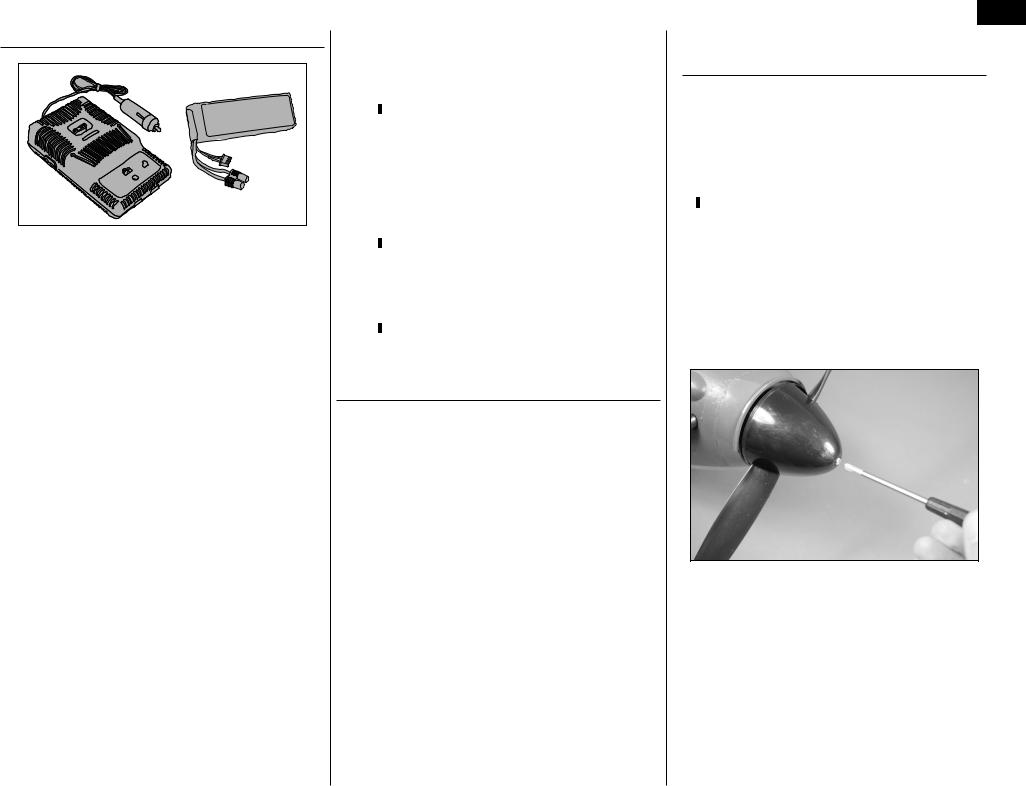
1. Use a #1 Phillips screwdriver to remove the 3mm x 8mm machine screw securing the spinner cone to the propeller nut.
5

EN
2. Remove the spinner cone by pulling the cone forward from the spinner backplate.
3. Use a 3/4-inch box wrench to remove the propeller nut from the motor adapter.
4. Remove the propeller from the motor adapter.
6
We recommend removing the spinner backplate and propeller adapter during the binding process as they can come loose if the motor starts and could cause damage to your work surface or personal injury.
5. When installing the propeller, use only the recommended 11.75 x 7 propeller listed. Use of a different sized propeller will change the load on the motor, and could damage the motor or speed control. Make sure the numbering on the propeller
faces to the front of the model as shown. Tighten the nut to ensure the propeller is secure.
6. Place the spinner cone in position and secure it using the 3mm x 8mm machine screw and a
#1 Phillips screwdriver. Make sure to position the spinner cone so it does not contact the propeller.
Battery Installation - BNF/PNP
Required Parts
Fuselage assembly Motor battery
1. Remove the canopy hatch from the fuselage by lifting the hatch at the rear. The canopy hatch
attaches to the fuselage using a magnet at the rear and pins at the front.
2. Locate the motor battery. If you are building the BNF version of this model, we recommend the battery be charged before it is installed. Slide the battery under the hook and loop straps. Use the straps to secure the battery in the fuselage.
Do not connect the lead from the battery to the speed control until instructed to do so.
E-flite Hurricane 25e PNP/BNF Assembly Manual
Transmitter and Receiver Binding - BNF
Required Parts
Fuselage assembly Transmitter
Bind plug
Binding is the process of programming the receiver of the control unit to recognize the GUID (Globally Unique Identifier) code of a single specific transmitter. You need to ‘bind’ your chosen Spektrum™ DSM2™/
DSMX™ technology equipped aircraft transmitter to the receiver for proper operation.
Note: Any JR® or Spektrum full range DSM2™/ DSMX™ transmitter can bind to the Spektrum
AR600 receiver. Please visit www.bindnfly.com for a complete list of compatible transmitters.
Note: When using a Futaba transmitter with a Spektrum DSM module, you must reverse the throttle channel.
BINDING PROCEDURE
BIND PLUG
1. Read transmitter instructions for binding to a receiver (location of transmitter’s Bind control).
2. Make sure transmitter is powered off.
3. Move the transmitter controls to neutral (flight controls: rudder, elevators and ailerons) or to low positions (throttle, throttle trim, and flight control trims).*
4. Install a bind plug in the receiver’s bind port.
5. Connect the flight battery to the ESC.
6. Power on the ESC switch. The receiver LED will begin to flash rapidly under the rear hatch.
E-flite Hurricane 25e PNP/BNF Assembly Manual
7. Power on the transmitter while holding the transmitter bind button or switch. Refer to your transmitter’s manual for binding button or switch instructions.
8. When the receiver binds to the transmitter, the light on the receiver will be solid and the ESC will produce a series of sounds. The series of sounds is a long tone, then 3 short tones that confirm the LVC is set for the ESC.
9. Remove the bind plug from the bind port in the receiver.
10. Safely store the bind plug (some owners attach the bind plug to their transmitter using two-part loops and clips).
11. The receiver should keep the binding to the transmitter until another binding is done.
* The throttle will not arm if the transmitter’s throttle control is not put at the lowest position.
If you encounter problems, obey binding instructions and refer to transmitter troubleshooting guide for other instructions. If needed, contact the appropriate Horizon Product Support office.
EN
Stabilizer Installation - BNF/PNP
Required Parts
Fuselage assembly Stabilizer assembly
Required Tools and Adhesives
30-minute epoxy |
Mixing stick |
Mixing cup |
Epoxy brush |
Petroleum jelly |
Paper towel |
Denatured alcohol |
|
Before installing the stabilizer, we highly recommend test fitting all parts before mixing epoxy. If the epoxy begins to cure before parts are assembled, it will be difficult to re-use items where epoxy has been applied.
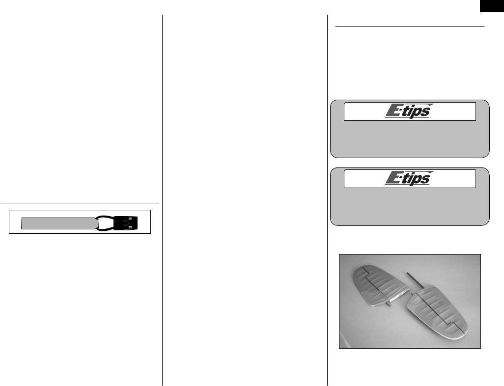
When installing the stabilizer, make sure to glue tube ONLY to the stabilizer. This will allow easy removal of the tube if the stabilizer becomes damaged and requires replacement.
1. Separate the stabilizer halves, leaving the tube in one of the stabilizer halves.
7
EN
2. Fit the stabilizer half to the fuselage by sliding the tube into position. The stabilizer will fit tightly in the plastic fairing.
3. Fit the other stabilizer half into position. Both halves will fit tightly in the fairing when installed. If not, check to make sure there is nothing from preventing them from seating fully.
8
Follow the procedure listed to apply the epoxy that will secure the tube in the stabilizer halves. This will allow you to remove the tube and stabilizer pieces from the fuselage if the stabilizer becomes damaged.
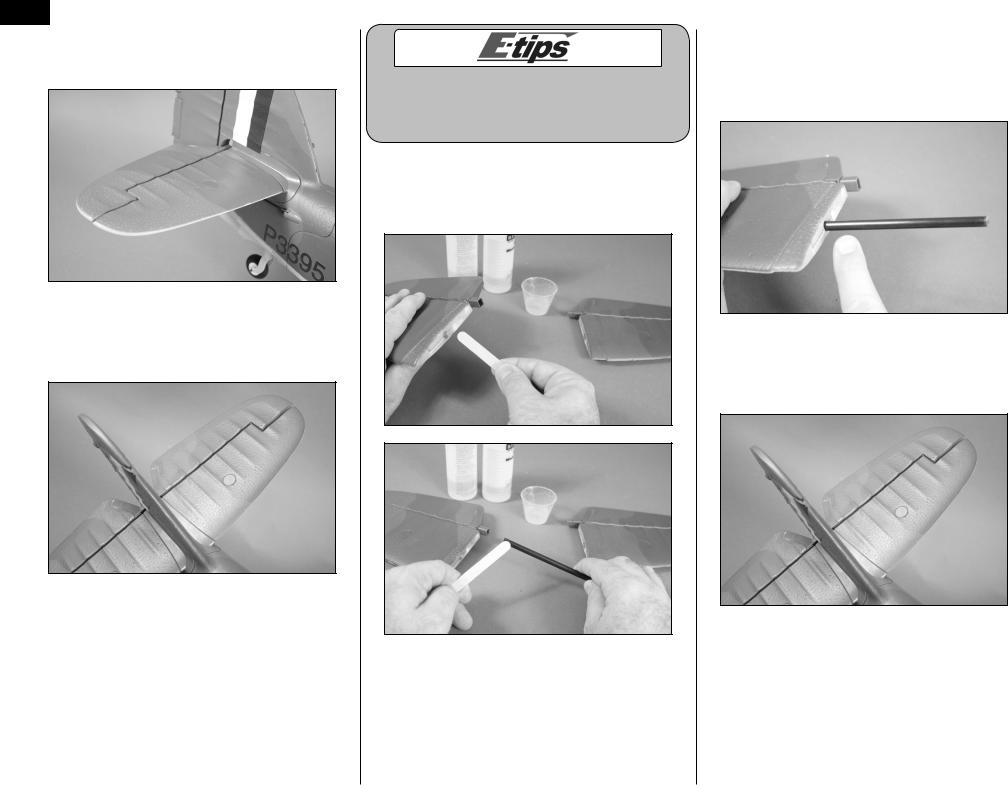
4. Remove the stabilizers from the fuselage, and the tube from both stabilizer halves. Apply a small amount of 30-minute epoxy to the end of the stabilizer tube and to the tube socket.
5. Slide the tube into the stabilizer half. Use a paper towel soaked with denatured alcohol to remove any excess epoxy. Apply a small amount of petroleum jelly to the first .50-inch (13mm) of the tube exposed outside of the stabilizer.
6. Slide the stabilizer in position as shown in step
2.Apply a small amount of epoxy to the end of the stabilizer tube and in the stabilizer as shown in step
4.Slide the remaining stabilizer into position.
E-flite Hurricane 25e PNP/BNF Assembly Manual
 Loading...