


Mini Edge 3D ARF
Table of contents
 Loading...
Mini Edge 540 3D
Assembly Manual

2
Table of Contents
Introduction ................................................................2
Specifications .............................................................2
Contents of Kit/Parts Layout .........................................
3
Required Electronics & Accessories ...............................
4
Recommended High Performance Motor Setup* .............
4
Extreme High Performance Motor Setup* ......................
5
Optional Accessories ..................................................
5
Additional Tools and Adhesives ....................................
5
Important Information About Motor Selection .................
6
Using the Manual .......................................................
6
Warning ....................................................................
6
Before Starting Assembly .............................................
6
Warranty Information ..................................................
7
Landing Gear Installation .............................................
8
Aileron Hinging ........................................................
12
Aileron Servos and Linkages ......................................
14
Wing Installation ......................................................
18
Stabilizer and Elevator ..............................................
19
Rudder and Fin ........................................................
22
Motor Installation ......................................................
25
Rudder and Elevator Servos .......................................
28
Receiver, Battery and ESC Install ................................
34
Canopy Install ..........................................................
36
Cowling Install .........................................................
38
Control Throws .........................................................
40
Center of Gravity ......................................................
41
Range Test Your Radio ...............................................
41
2005 Official AMA
National Model Aircraft Safety Code ......4
2
Introduction
Thank you for purchasing the Mini Edge 540 3D ARF,
which is based on the popular 33% Hangar 9® Edge 540
and is capable of the same extreme 3D performance you
get with larger models. Backed by E-flite’s high quality
reputation, the Mini Edge 540 should provide you with the
superior performance and features you are looking for in an
aerobatic park flyer.
We provide a 6.6:1 gearbox and a 12 x 6 propeller so you
can easily add our E-flite™ Park 400 Brushless motor for
extreme performance. The Mini Edge features lightweight
balsa and light-ply construction, UltraCote® covering,
fiberglass cowl and wheel pants, and carbon fiber landing
gear. The mid-wing design makes it ideal for aerobatics such
as hovering and other precision 3D maneuvers.
Specifications
Wingspan: 37.25" (945 mm)
Length: 34" (860 mm)
Wing Area: 297 sq in (19 sq dm)
Weight w/o Battery: 20–21 oz (570–595 g)
Weight w/ Battery: 24–26 oz (680–740 g)
3
Large Replacement Parts:
EFL2226 Wing Set with Ailerons
EFL2227 Fuselage with Hatch
EFL2228 Tail Set
EFL2230 Main Landing Gear
EFL2231 Fuse Hatch
EFL2232 Canopy
EFL2233 Painted Cowl
EFL2234 Painted Wheel Pants
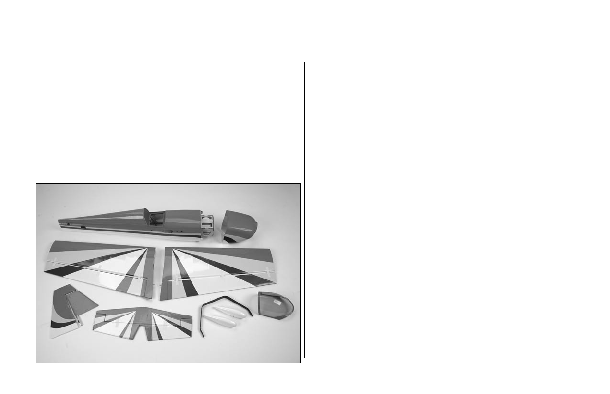
Contents of Kit/Parts Layout
Small Replacement Parts
EFL2086 Hook & Loop Tape
EFL2229 Pushrod Set
EFL2235 Wing Tube
EFL2236 Stick Motor Mount
EFLA200 Micro Control Horns
EFLA202 Micro Tail Skid
EFLA203 Micro Control Connectors
EFLA213 E-flite/JR/Horizon Decals
EFLA214 Micro Pull-Pull Set
EFLA216 Spinner
EFLA221 Foam Park Wheels, 1.5"
EFLM207 Pinion Gear, 10T 0.4 Module
EFLM221 Gearbox, 6.6:1
EFLM222 Spur Gear, 66T w/Shaft
EFLP1260 12 x 6 Slow Flyer Prop (includes only 1)

4
Required Electronics & Accessories
JRP6654** 6102FM, R610UL & 4-S241—Complete
Radio System
JRPR610UL** R610UL 6CH FM Receiver, Shrinkwrap
JRPS241 S241 Sub-Micro Servo (4)
JRPA212 Large Arms w/Screws (2)
JRPA095 6" Servo Extension (2)
JRPA098 12" Servo Extension
EFLA311B 20A Brushless ESC (version 2)
EFLC3005 Celectra 1–3 Cell Li-Po Charger
EFLA250 Park Flyer Tool Assortment, 5-pc
Recommended High Performance
Motor Setup*
EFLM1105 Park 400 Brushless Motor, 3700Kv
EFLM1912 Heat Sink, 20mm x 20mm: Park 400
EFLP1260 12 x 6 Slow Flyer Prop
(keep extras on hand)
EFLB1035 11.1V 2100mAh 3-Cell Li-Po, 16GA or
THP21003S 2100mAh 3-Cell 11.1V Li-Po, 16GA
* Use with included 12 x 6 prop, 6.6:1 gearbox, and 10T
pinion. Proper throttle management is required when using
high performance setups. Always monitor motor temperature
and gearbox wear.

5
Extreme High Performance
Motor Setup*
EFLM1100 Park 400 Brushless Motor, 4200Kv
EFLM1912 Heat Sink, 20mm x 20mm: Park 400
EFLP1260 12 x 6 Slow Flyer Prop
(keep extras on hand)
EFLB1035 11.1V 2100mAh 3-Cell Li-Po, 16GA or
THP21003S 2100mAh 3-Cell 11.1V Li-Po, 16GA
* Use with included 12 x 6 prop, 6.6:1 gearbox, and 10T
pinion. Proper throttle management is required when using
high performance setups. Always monitor motor temperature
and gearbox wear.
Optional Accessories
EFLA110 Power Meter
EFLA212 Gear Puller: 1–5mm Shaft
JRPS281 DS281 Micro Digital Servo (4)
Additional Tools and Adhesives
Tools & Equipment
Hobby knife Square
Ruler Felt-tipped pen
T-pins Paper towel / tissue
Heat gun
Wax paper String
Tape Pliers
Drill Drill bit: 1/16" (2mm), 1/8" (3mm)
150–180 Grit sandpaper
Hex wrench: 3/32" (EFLA251 - included with EFLA250)
Nut driver: 5.5mm (EFLA255 - included with EFLA250)
Small Phillips screwdriver (EFLA257 - included with
EFLA250)
Adhesives
Thin CA Medium CA
Canopy glue Threadlock
6-Minute Epoxy - (HAN8000)

6
Warning
An RC aircraft is not a toy! If misused, it can cause serious
bodily harm and damage to property. Fly only in open
areas, preferably at AMA (Academy of Model Aeronautics)
approved flying sites, following all instructions included with
your radio.
Lithium Polymer batteries are significantly more volatile
than alkaline or Ni-Cd/Ni-MH batteries used in RC
applications. All manufacturer’s instructions and warnings
must be followed closely. Mishandling of Li-Po batteries can
result in fire.
Before Starting Assembly
Before beginning the assembly of your Mini Edge, remove
each part from its bag for inspection. Closely inspect the
fuselage, wing panels, rudder and stabilizer for damage. If
you find any damaged or missing parts, contact the place of
purchase.
Important Information About Motor
Selection
We are recommending either the E-flite™ Park 400
Brushless Motor with 4200Kv (EFLM1100) or the version
with 3700Kv (EFLM1105). The 3700Kv motor provides
plenty of power for sport and entry-level 3D pilots with the
ability to hover and climb vertically using the stock 6.6:1
gearbox and 12 x 6 propeller. This motor will draw less
current and provide longer flight duration. The 4200Kv
motor should only be used by experienced pilots who
manage throttle appropriately. This motor will provide even
better vertical performance at the expense of flight duration
due to the increased current draw. It is extremely important
to monitor gearbox wear and motor temperature when using
the 4200Kv motor. Lack of proper throttle management using
this motor may result in damage to the motor, gearbox, ESC,
and battery.
Using the Manual
This manual is divided into sections to help make assembly
easier to understand, and to provide breaks between each
major section.
Remember to take your time and follow the directions.

7
Warranty Information
Horizon Hobby, Inc. guarantees this kit to be free from
defects in both material and workmanship at the date of
purchase. This warranty does not cover any component parts
damage by use or modification. In no case shall Horizon
Hobby’s liability exceed the original cost of the purchased
kit. Further, Horizon Hobby reserves the right to change or
modify this warranty without notice.
In that Horizon Hobby has no control over the final assembly
or material used for the final assembly, no liability shall be
assumed nor accepted for any damage resulting from the
use of the final assembled product. By the act of using the
assembled product, the user accepts all resulting liability.
Please note that once assembly of the model has been
started, you must contact Horizon Hobby, Inc. directly
regarding any warranty question. Please do not contact
your local hobby shop regarding warranty issues, even if
that is where you purchased it. This will enable Horizon to
better answer your questions and service you in the event
that you may need any assistance.
If the buyer is not prepared to accept the liability associated
with the use of this product, the buyer is advised to return this
kit immediately in new and unused condition to the place of
purchase.
Horizon Hobby, Inc.
4105 Fieldstone Road
Champaign, Illinois 61822
877-504-0233
horizonhobby.com
8
Landing Gear Installation
Required Parts
Fuselage Carbon main gear
Tail skid Wheel pant (2)
1
1
/
2
" (38mm) wheel (2) 2mm x 25mm screw (2)
2mm nut (4) #4 washer (black) (2)
4-40 x 1/2" socket screw (2) 2mm washer (4)
2mm x 6mm wood screw (2)
Required Tools and Adhesives
Threadlock 1/8" (3mm) drill bit
Drill Medium CA
Hobby knife Hex wrench: 3/32"
Phillips screwdriver (small)
Note: You may consider using a larger
diameter wheel, such as 2 1/4 in, if your
flying site has rough terrain. By using a
larger wheel, you will not be able to use the
included wheel pants.
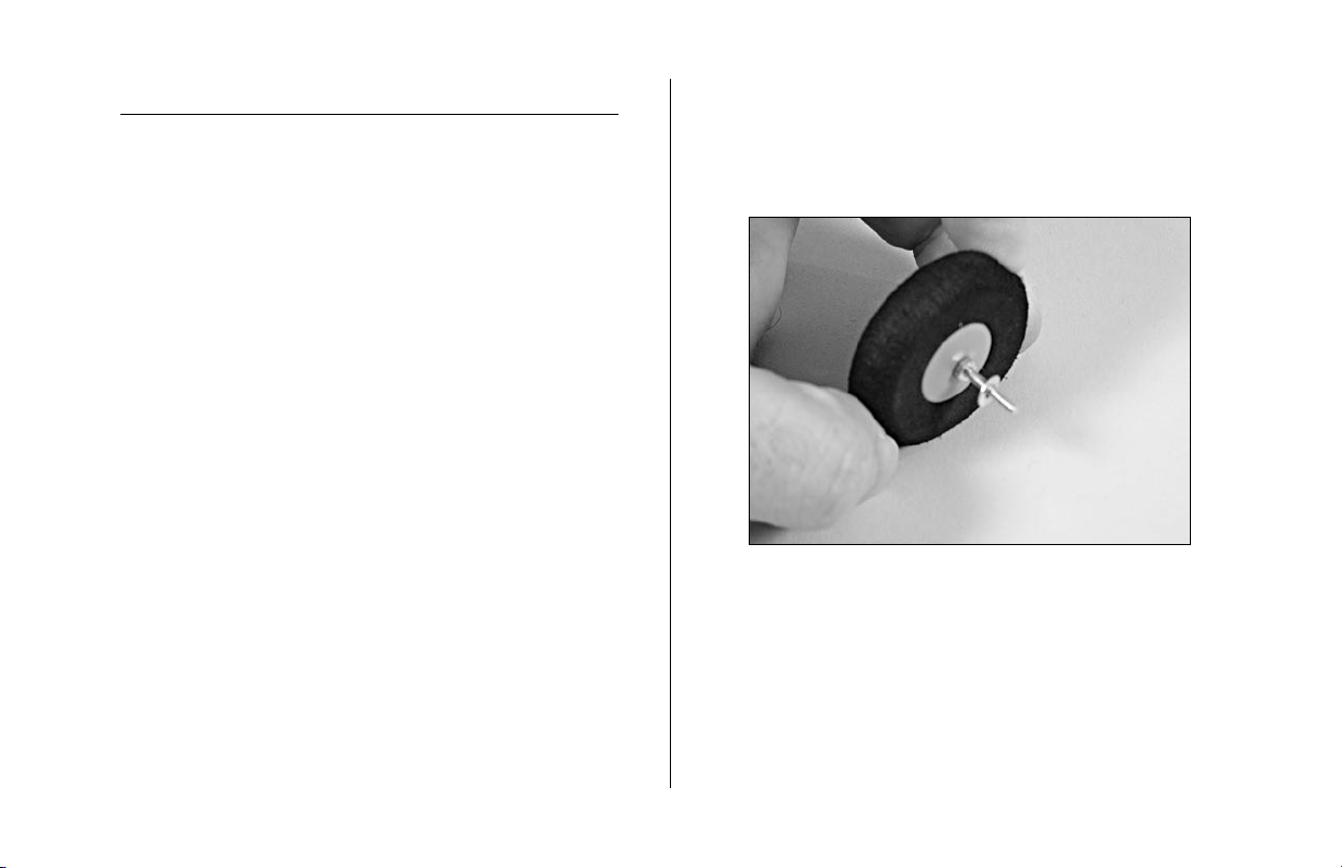
1. Slide the 2mm x 25mm screw through one of the
wheels. Thread a 2mm nut onto the screw. Slide a
2mm washer onto the screw. This will all fit inside the
wheel pant.
9
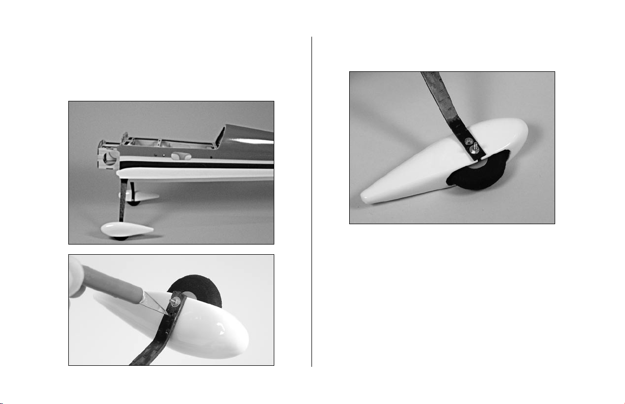
2. Fit the assembly from Step 1 into the wheel pant.
Use a 2mm washer and nut to attach the wheel to the
lower hole on the landing gear.
Note: Use threadlock on both nuts to prevent
them from loosening during flight.
3. Repeat Steps 1 and 2 for the remaining wheel
and pant.
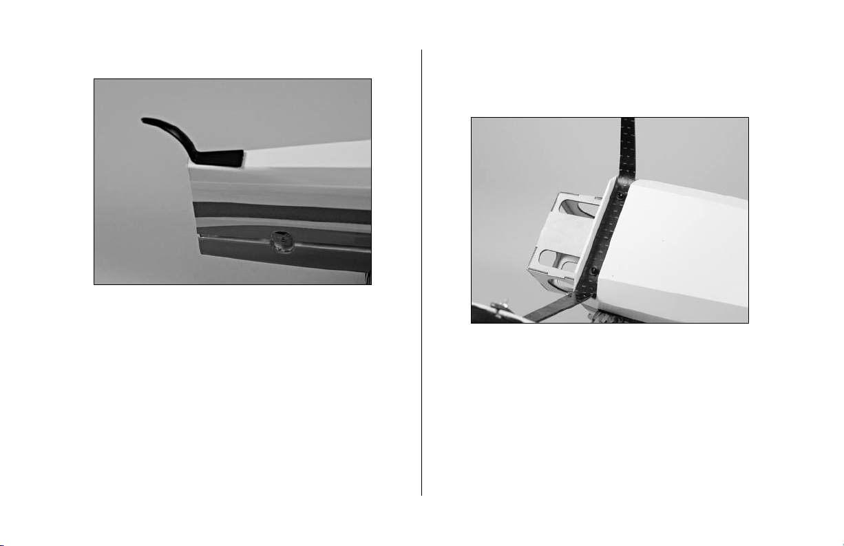
4. Drill 1/8" (3mm) holes in the tail for the tail skid.
10
5. Glue the tail skid into position using Medium CA. 6. Attach the landing gear using a 3/32" hex wrench,
two 4-40 x 1/2" socket head screws and two #4
washers (black).
11
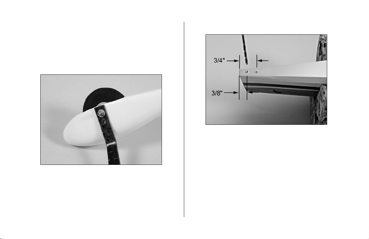
7. Place the fuselage on its wheels and position the
wheel pants parallel to the work surface. Drill a hole
through the landing gear into each wheel pant using
a hobby knife.
8. Secure the location of the wheel pants using 2mm x
6mm wood screws and a small Phillips screwdriver.
12
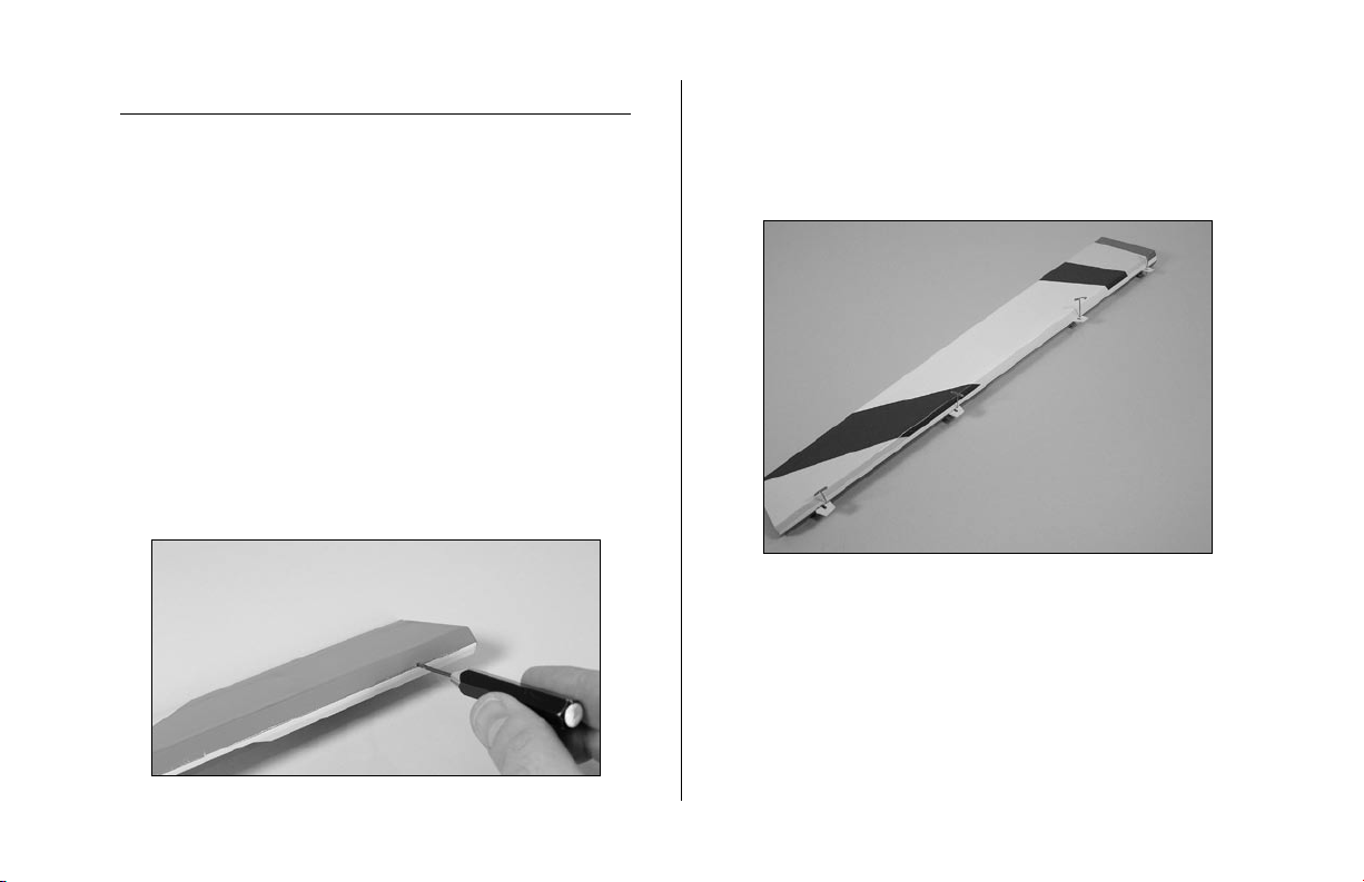
2. Slide four hinges into the slits in the aileron. Center
the slot in the hinge with the hole drilled in Step 1.
Place a T-pin in each hinge to prevent it from being
pushed into the wing when installing the aileron.
Note: Do not use CA accelerator during the
hinging process. The CA must be allowed to
soak into the hinge to provide the best bond.
Using accelerator will not provide enough time
for this process.
Aileron Hinging
Required Parts
Wing (left and right) Aileron (left and right)
CA hinges (8)
Required Tools and Adhesives
1/16" (2mm) drill bit Drill
T-pins Thin CA
Paper towel
1. Locate the positions for the hinges. Drill a 1/16"
(2mm) hole in the center of each slot of both the wing
and aileron. This creates a tunnel for the CA, allowing
the CA to penetrate into the hinge better, bonding the
hinges more securely.
13
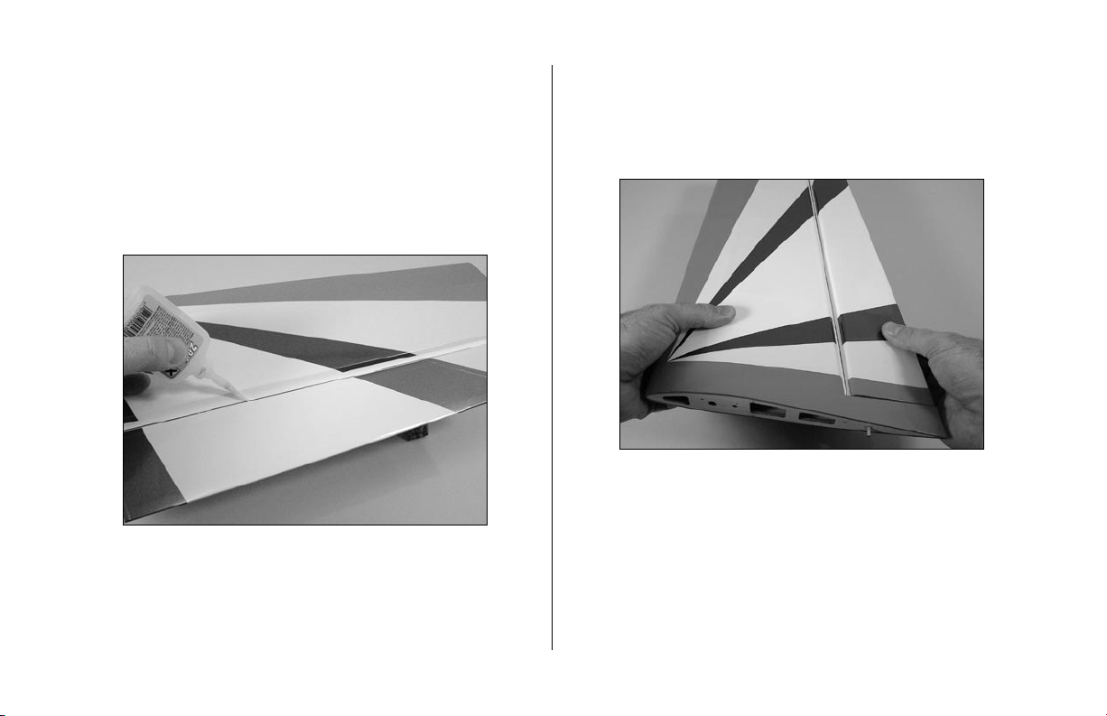
3. Slide the aileron into position. Check to make
sure it can move without interference at the wing
root. Remove the T-pins and apply Thin CA to each
hinge. Make sure the hinge is fully saturated with CA.
Use a paper towel to clean up any excess CA from
the wing and aileron. Make sure to apply CA to both
sides of the hinge.
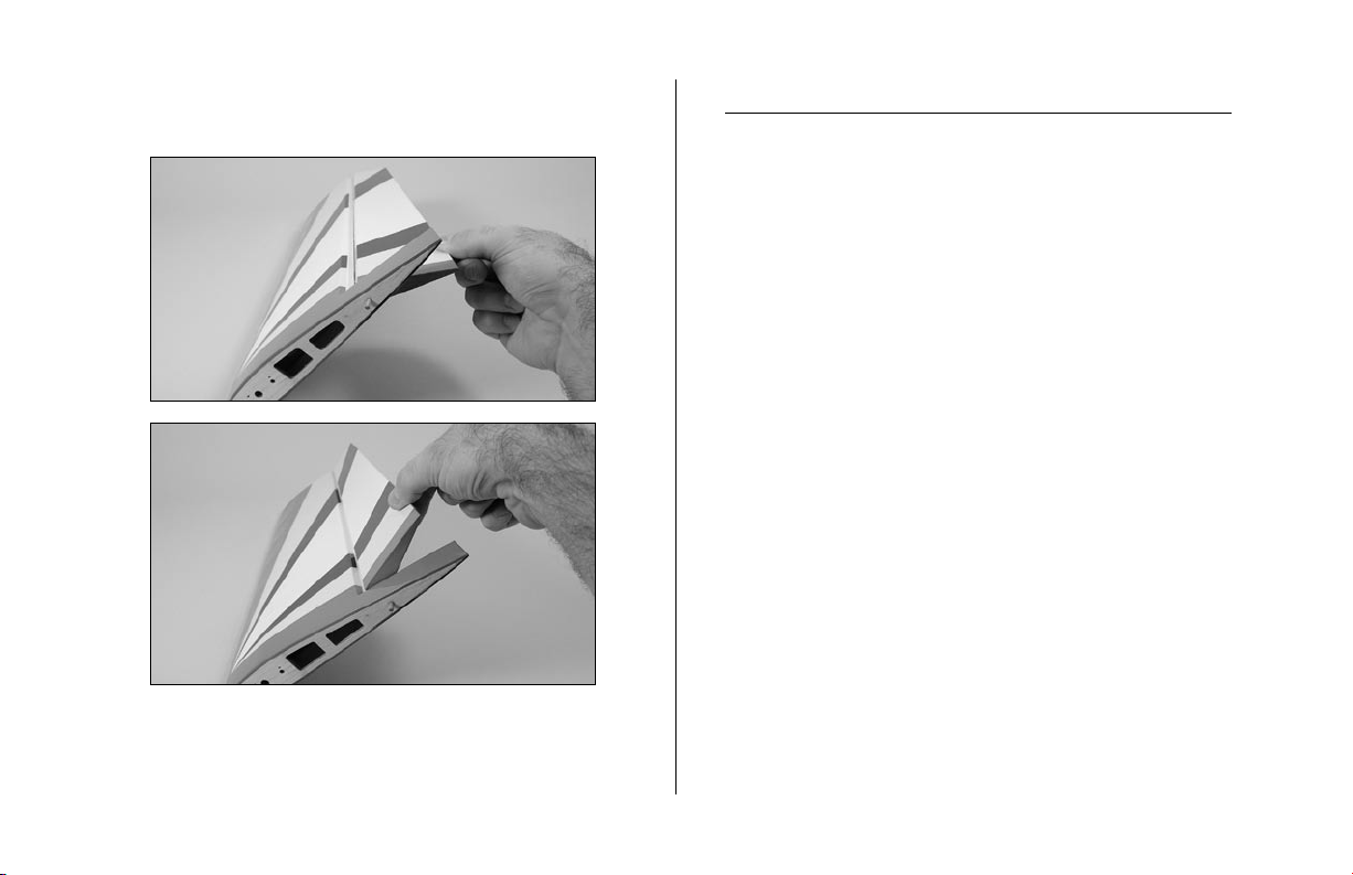
4. Firmly grasp the wing and aileron and gently pull
on the aileron to ensure the hinges are secure and
cannot be pulled apart. Use caution when gripping the
wing and aileron to avoid crushing the structure.
14
5. Work the aileron up and down several times to
work in the hinges and check for proper movement.
6. Repeat Steps 1 through 5 for the remaining aileron.
Aileron Servos and Linkages
Required Parts
Wing panel (right and left)
Micro control connector (2)
2mm x 4mm screw (2)
3
3
/
8
" (85 mm) pushrod (2)
Control horn and backplate (2)
Servos: JR 241 Sub-micro servo (JRPS241) (2)
Large Arm w/Screws (JRPA212) (2)
Required Tools and Adhesives
Hobby knife 6-minute epoxy
6" (150mm) servo extension (2) String
Phillips screwdriver (small)
Loading...