


Cessna 150 Aerobat 250 ARF
Cessna 150 Aerobat 250 ARF
Assembly Manual

2 E-flite Cessna 150 Aerobat 250 ARF Assembly Manual
Notice
All instructions, warranties and other collateral
documents are subject to change at the sole
discretion of Horizon Hobby, Inc. For up-to-date
product literature, visit http://www.horizonhobby.
com and click on the support tab for this product.
Meaning of Special Language
The following terms are used throughout the product
literature to indicate various levels of potential harm
when operating this product:
NOTICE: Procedures, which if not properly followed,
create a possibility of physical property damage
AND a little or no possibility of injury.
CAUTION: Procedures, which if not properly followed,
create the probability of physical property damage
AND a possibility of serious injury.
WARNING: Procedures, which if not properly followed,
create the probability of property damage, collateral
damage, and serious injury OR create a high
probability of superficial injury.
WARNING: Read the ENTIRE instruction
manual to become familiar with the features of the
product before operating. Failure to operate the
product correctly can result in damage to the
product, personal property and cause serious injury.
This is a sophisticated hobby product and NOT a
toy. It must be operated with caution and common
sense and requires some basic mechanical
ability. Failure to operate this Product in a safe
and responsible manner could result in injury or
damage to the product or other property. This
product is not intended for use by children without
direct adult supervision. Do not attempt disassembly,
use with incompatible components or augment
product in any way without the approval of Horizon
Hobby, Inc. This manual contains instructions for
safety, operation and maintenance. It is essential to
read and follow all the instructions and warnings
in the manual, prior to assembly, setup or use, in
order to operate correctly and avoid damage or
serious injury.
Warnings
Read and follow all instructions and safety precautions
before use. Improper use can result in fire, serious
injury and damage to property.
Age Recommendation: Not for children under
14 years. This is not a toy.
COMPONENTS
Use only with compatible components. Should any
compatibility questions exist, please refer to the
product instructions, the component instructions or
contact Horizon Hobby, Inc.
FLIGHT
Fly only in open areas to ensure safety. It is
recommended flying be done at AMA (Academy of
Model Aeronautics) approved flying sites. Consult local
laws and ordinances before choosing a location to fly
your aircraft.
PROPELLER
Keep loose items that can get entangled in the
propeller away from the prop, including loose clothing
or other objects such as pencils and screwdrivers.
Especially keep your hands away from the propeller as
injury can occur.
BATTERIES
Notes on Lithium Polymer Batteries
When misused, lithium polymer batteries are
significantly more volatile than alkaline or Ni-Cd/
Ni-MH batteries used in RC applications. Always
follow the manufacturer’s instructions when using and
disposing of any batteries. Mishandling of Li-Po batteries
can result in fire causing serious injury and damage.
SMALL PARTS
This kit includes small parts and should not be left
unattended near children as choking and serious injury
could result.
SAFETY PRECAUTIONS
• Checkallcontrolsurfacespriortoeachtakeoff.
• Donotflyyourmodelnearspectators,parkingareas
or any other area that could result in injury to people
or damage of property.
• Donotflyduringadverseweatherconditions.
Poor visibility and/or strong winds can cause
disorientation and loss of control of your aircraft.
• Donottakechances.Ifatanytimeduringflightyou
observe any erratic or abnormal operation, land
immediately and do not resume flight until the cause
of the problem has been ascertained and corrected.
Safety can never be taken lightly.
• Donotflynearpowerlines.

3E-flite Cessna 150 Aerobat 250 ARF Assembly Manual
Important Information
Regarding Warranty Information
Please read our Warranty and Liability Limitations
section before building this product. If you as the
Purchaser or user are not prepared to accept the
liability associated with the use of this Product, you are
advised to return this Product immediately in new and
unused condition to the place of purchase.
Specifications
Wingspan: 37.9 in (960mm)
Length: 27.2 in (690mm)
Wing Area: 196 sq in (12.6 sq dm)
Weight with battery: 12.0–13.7 oz
(340–388 g)
Weight w/o battery: 10.9–12.2 oz
(309–346 g)
Using the Manual
This manual is divided into sections to help make
assembly easier to understand and to provide breaks
between each major section. In addition, check boxes
have been placed next to each step to keep track
of its completion. Steps with a single circle () are
performed once, while steps with two or more circles
() indicate the step will require repeating, such as
for a right or left wing panel, two servos, etc.
Remember to take your time and follow the directions.
Introduction
The Cessna 150, while designed over 50 years ago,
to this day has a personality and spirit all its own.
Considered still tame enough for training, the Aerobat
version appealed to casual pilots that needed a jolt
to become even more proficient. This 250-size ARF
version is for RC pilots wanting the thrill of basic
aerobatics in a small yet detailed package. This clever,
all-wood model remarkably maintains the subtle curves
and character of the original aircraft, yet is distinctively
detailed with a checker-scheme that honors the
character of the Aerobat. Despite its compact size, you
get these great features like an: authentic scale outline,
laser cut engineering, fiberglass cowl and wheel pants,
and a lightweight UltraCote
®
ParkLite
™
trim scheme.
The magnetically secured wing panels and cowling
make for quick assembly and the oversized quick-
release accessory hatch allows easy access for radio
and battery installation. The steerable nose strut makes
ground handling a breeze and the optional aluminum
spinner (EFLSP100) adds the perfect finish to the
model.
Table of Contents
Notice ......................................................................2
Meaning of Special Language ...................................2
Warnings ................................................................. 2
Introduction .............................................................. 3
Important Information Regarding
Warranty Information ....................................... 3
Specifications ...........................................................3
Using the Manual .....................................................3
Contents of Kit/Parts Layout ......................................4
Covering Colors ........................................................ 4
Hardware/Accessory Sizes .......................................4
Recommended Radio Equipment ................................ 4
Park 250 Motor Setup ...............................................4
Park 280 Motor Setup ...............................................4
Optional Accessories ................................................4
Required Tools and Adhesives ...................................4
Before Starting Assembly ..........................................5
Aileron Servo Installation ..........................................5
Rudder and Elevator Servo Installation .......................8
Landing Gear Installation ........................................10
Motor and Speed Control Installation .......................14
Receiver Installation................................................. 15
Horizontal Stabilizer Installation .............................. 16
Vertical Stabilizer Installation ...................................19
Rudder, Elevator and Nose Gear
Linkage Installation .........................................21
Windscreen, Wing and Wing Strut Installation ......... 23
Motor Battery, Cowl, Propeller and
Spinner Installation .........................................25
Decal Installation ....................................................27
Center of Gravity .................................................... 27
Control Throws .......................................................28
Preflight ..................................................................28
Range Test Your Radio ............................................. 29
Flying Your Model ...................................................29
Daily Flight Checks ................................................. 29
Limited Warranty .................................................... 30
Warranty Services ..................................................30
Compliance Information for the European Union ...... 31
Academy of Model Aeronautics
National Model Aircraft Safety Code ..............32
Building and Flying Notes ................................. 33–34
4 E-flite Cessna 150 Aerobat 250 ARF Assembly Manual
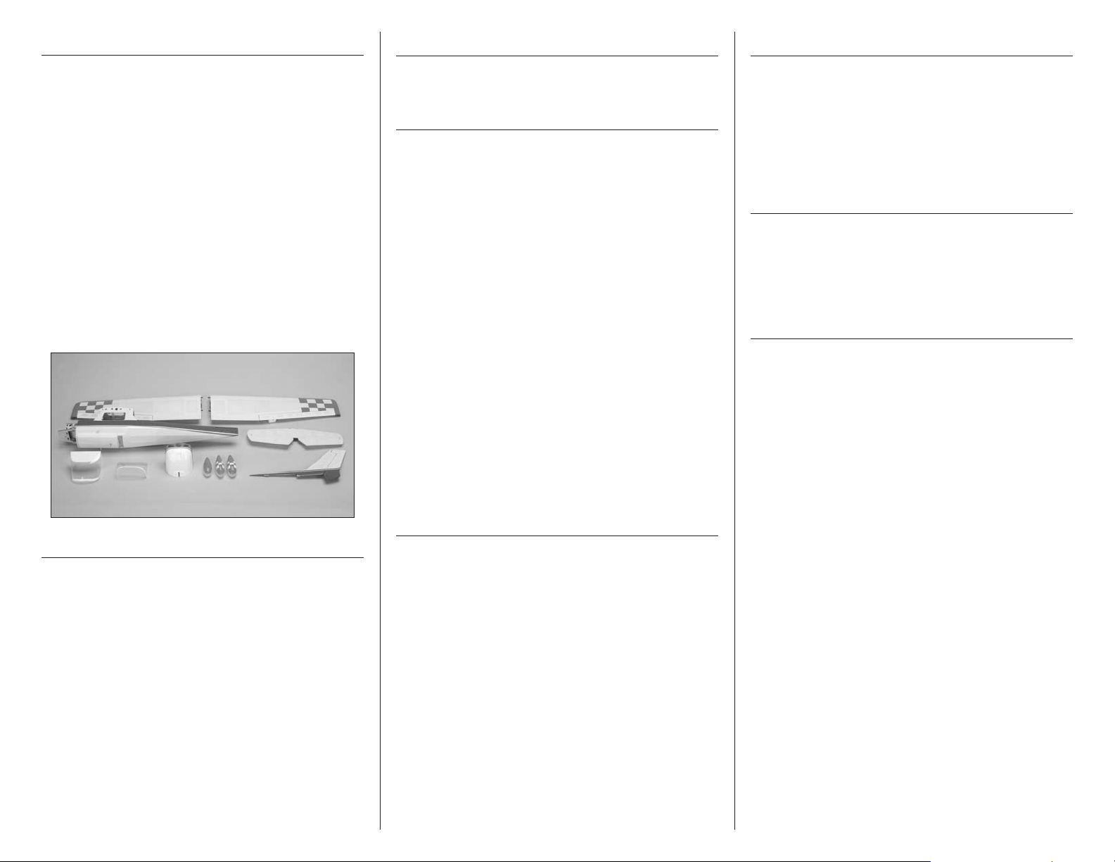
Contents of Kit/Parts Layout
Replacement Parts
EFL505001 Fuselage
EFL505002 Wing Panels left and right
EFL505003 Tail Set
EFL505004 Landing Gear Set
EFL505005 Cowling
EFL505006 Windshields
EFL505007 Hardware
EFL505008 Pushrods
EFL505009 Main Struts
EFL505010 Wing Tube
EFL505011 Wheel Pant Set
EFL505012 Decal Set
EFL505013 Wheel Set:
40mm (2), 35mm (1)
EFL505014 Main Hatch
Covering Colors
ParkLite, Orange HANU0814
ParkLite, True Red HANU0815
ParkLite, White HANU0801
Hardware/Accessory Sizes
Main wheel 1.57-inch (40mm)
Nose wheel 1.37-inch (35mm)
Recommended Radio Equipment
You will need a minimum 4-channel transmitter,
receiver and four servos.
Recommended Transmitter
SPMR5510 DX5e DSMX
®
5-Channel
Transmitter Only
Additional Items
SPMAR6300 AR6300 DSM2
™
Nanolite
6-Channel Receiver
EFLRDS35 DS35 Digital Super
Sub-Micro Servo (4)
SPMEXJST3UL 3-inch (76mm) Ultralight JST
Servo Extension (2) (rudder
and elevator extensions)
SPMEXJST6UL 6-inch (152mm) Ultralight JST
Servo Extension (4) (aileron
wing extension (2) and aileron
to fuselage extension (2))
SPMYHJST3UL 3-inch (76mm) Ultralight JST
Y-Harness (aileron to fuselage
extension Y-harness)
Park 250 Motor Setup
EFLM1130 Park 250 Brushless Outrunner
Motor, 2200Kv
EFLA1010 10-Amp Pro Brushless ESC
EFLB4302SJ 430mAh 2S 7.4V 20C Li-Po,
20AWG
GWSEP7035B 7 x 3.5 Direct Drive Propeller
Park 280 Motor Setup
EFLM1140 Park 280 Brushless Outrunner
Motor, 1800Kv
EFLA1010 10-Amp Pro Switch-Mode BEC
Brushless ESC
EFLB4503SJ30 450mAh 3S 11.1V 30C LiPo,
18AWG JST
GWSEP7035B 7 x 3.5 Direct Drive Propeller
Optional Accessories
EFLSP100 1.00-inch Aluminum Spinner
with 2mm Collet
EFLA110 Power Meter
EFLC3025 Celectra
™
80W AC/DC Multi-
Chemistry Battery Charger
Required Tools and Adhesives
Tools & Equipment
Dental floss Paper towels
Felt-tipped pen Flat blade screwdriver: 1.5mm
Flat file Hemostat
Hex wrench: 1.5mm Hobby knife with #11 blade
Low-tack tape Open-end wrench: 6mm
Pencil Phillips screwdriver: #0, #1, #2
Pin vise Razor saw
Ruler Scissors
Square Toothpicks
Rubbing alcohol Side cutters
Drill bit: #56/.046 (1mm), 1/16-inch (1.5mm),
5/64-inch (2mm)
Optional Tools & Equipment
Balancing stand (optional)
Adhesives
Medium CA PAAPT02
Thin CA PAAPT08
Threadlock PAAPT42
Canopy Glue PAAPT56
5E-flite Cessna 150 Aerobat 250 ARF Assembly Manual
Before Starting Assembly
Before beginning the assembly of your model, remove
each part from its bag for inspection. Closely inspect
the fuselage, wing panels, rudder and stabilizer for
damage. If you find any damaged or missing parts,
contact the place of purchase.
If you find any wrinkles in the covering, use a heat gun
(HAN100) and covering glove (HAN150) or covering
iron (HAN101) with a sealing iron sock (HAN141) to
remove them. Use caution while working around seams
or areas where the colors overlap to prevent pulling
the seams.
During the course of building your model, we
suggest you use a soft base for the building surface.
Such things as a foam stand, large piece of
bedding foam or a thick bath towel will work well
and help protect the model from damage during
assembly. This is not shown in the instructions
to provide the greatest detail in the photos.
When referencing directions (up, down, left,
right, top and bottom), take note that these are
in relationship to the pilot sitting in the cockpit
of the aircraft unless noted otherwise.
Aileron Servo Installation
Required Parts
Wing panel (right and left)
Transmitter Receiver
Receiver battery Servo with accessories (2)
2mm x 5mm self-tapping screw (8)
Aileron pushrod, 2.75-inch (78mm) (2)
6-inch (152mm) servo extension (2)
Pushrod connector with hardware (2)
Required Tools and Adhesives
Medium CA Phillips screwdriver: #0, #1
Pin vise Thin CA
Pencil Dental floss
Toothpicks Side cutters
Drill bit: 1/16-inch (1.5mm), 5/64-inch (2mm)
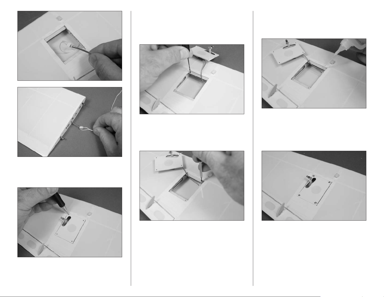
1. Use the radio system to center the aileron servos.
Use a # 0 Phillips screwdriver to center both of the
stock arms so they are centered perpendicular to the
servo. Make one of each shown for the left and right
wing. Attach the mounting bracket to the servos as
shown.
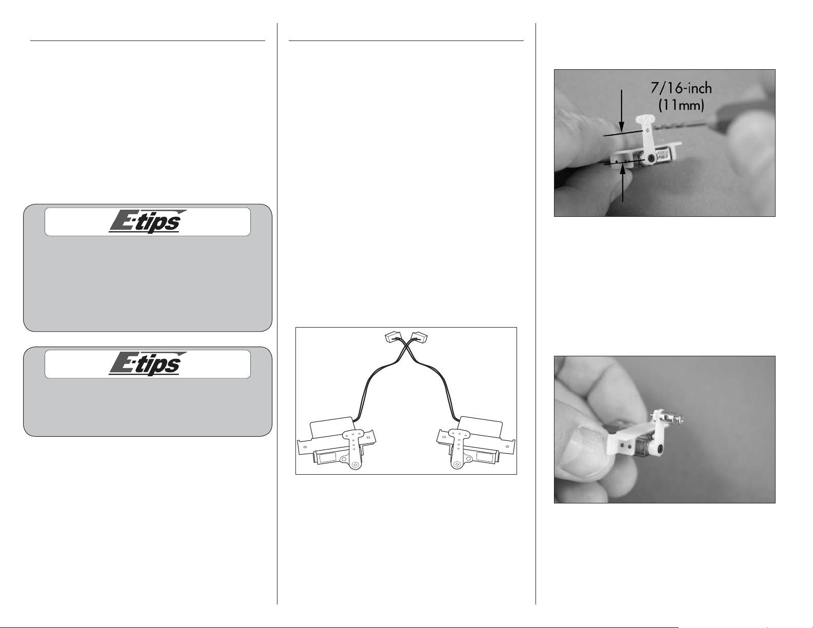
2. Use a pin vise and 5/64-inch (2mm) drill bit to
enlarge the hole that is second from the inside on
the servo arm.
3. Use side cutters to remove the excess servo arm
as shown. Attach the pushrod connector to the
servo horn using the hole enlarged in the previous
step. The washers that come on the connector are
not needed and can be removed. Tighten the nut
so that it is secure on the arm but is not tight. There
should be a small amount of play between the arm
and the connector and the connector should be able
to rotate freely on the arm.
6 E-flite Cessna 150 Aerobat 250 ARF Assembly Manual
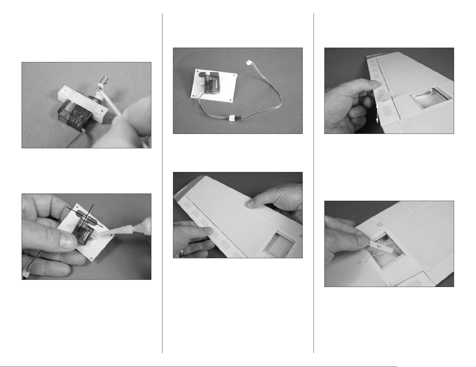
4. Use a very small amount of medium CA on a
toothpick to secure the nut to the bottom of the
connector threads. Do not use thin CA for this
step as it can wick through the nut and glue the
connector to the arm. Make sure the connector still
rotates freely in the arm after the glue is cured.
5. Place the servo on the aileron servo cover. Center
the servo arm in the opening, then use medium CA
to glue the mount to the cover. Use care not to get
glue under the servo.
6. Connect a 6-inch (152mm) servo extension to
the servo lead. Use a piece of dental floss to secure
the leads so they do not accidentally disconnect
inside the wing.
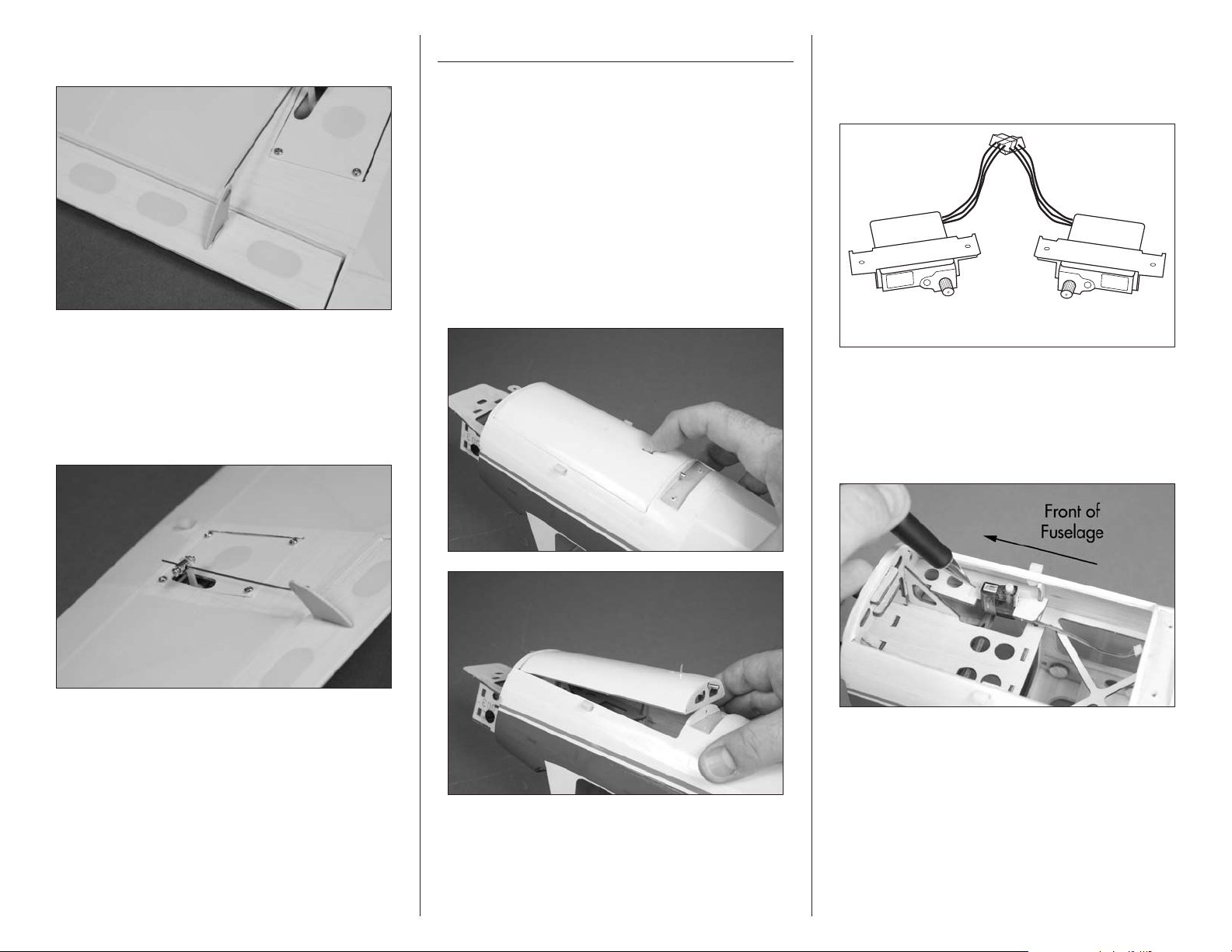
7. Check that the hinges are secure by gently pulling
on the control surface. If not, apply thin CA to any
hinges that are not glued and recheck.
8. Move the control surface through its range of
motion several times to break in the hinges. This
will reduce the initial load on the servo during
your first flights.
9. A string is located in the wing to pull the servo
lead through the wing. Remove the string from the
wood support and tie the string to the end of the
servo lead as shown. Pull the servo lead through
the wing using care not to damage the internal
structure. Once the lead is routed through the wing,
remove the string from the lead.
7E-flite Cessna 150 Aerobat 250 ARF Assembly Manual
10. Place the servo cover in position on the wing.
Use a pencil to mark the locations for the four
mounting screws.
11. Use a pin vise and 1/16-inch (1.5mm) drill bit
to drill four holes for the mounting screws. Use care
not to accidentally puncture the covering on the top
of the wing or to push too hard on the mounting
rails, as this could break them.
12. Use a #1 Phillips screwdriver to thread a 2.5mm
x 8mm washer-head self-tapping screw into each
of the holes to cut threads in the surrounding wood.
Remove the screw before moving to the next step.
13. Apply 2–3 drops of thin CA in each of the holes
to harden the surrounding wood. This will harden
the threads so the screws do not easily strip the
surrounding wood.
14. Use a #1 Phillips screwdriver and four 2mm x
5mm self-tapping screws to secure the cover to the
wing. Note that the servo arm is aligned with the
aileron control horn and the hole in the mounting
plate is facing forward.
8 E-flite Cessna 150 Aerobat 250 ARF Assembly Manual
15. With the aileron servo centered, attach the
Z-bend of the pushrod to the control horn.
16. Pass the pushrod through the pushrod connector
and center the aileron. Use a #1 Phillips screwdriver
to tighten the screw in the pushrod connector to
secure the pushrod wire. Use side cutters to remove
the excess wire. Support the clevis and the wire
while doing this to not damage the model.
17. Repeat steps 2 through 16 to install the
remaining aileron servo.
18. Check to make sure the radio system has been
turned off before proceeding.
Rudder and Elevator Servo Installation
Required Parts
Fuselage Servo with hardware (2)
3-inch (76mm) servo extension (2)
Required Tools and Adhesives
Pencil Phillips screwdriver: #0
Pin vise Drill bit: #56.046-inch (1mm)
Thin CA Dental floss
1. Remove the battery hatch cover from the fuselage
by sliding the locking pin forward. The front of the
hatch is held in place by a tab at the front. Set the
cover aside until it is required later in the manual.
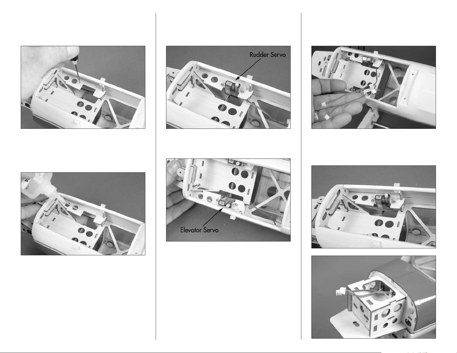
2. Prepare the rudder and elevator servos by using
a #0 Phillips screwdriver to remove the servo horns
from the servos. Attach the mounting bracket to the
servos as shown.
Rudder Elevator
3. Position the rudder servo in the fuselage. Locate
the servo so the outer edge is against the outer
edge of the mounting rail and centered between the
front and rear. Use a pencil to mark the locations
for the two mounting screws.
9E-flite Cessna 150 Aerobat 250 ARF Assembly Manual
4. Use a pin vise and a #56/.046-inch (1mm) drill
bit to drill the holes for the mounting screws. Use
care not to push too hard on the mounting rails as
this could damage them.
5. Apply 2–3 drops of thin CA in each of the holes
to harden the surrounding wood. This will harden
the threads so the screws do not easily strip the
surrounding wood.
6. Use the screws provided with the servo and a #0
Phillips screwdriver to secure the rudder servo in
the fuselage. Use care not to push too hard on the
mounting rails while tightening the screws.
7. Repeat steps 3 through 6 to install the elevator
servo in the fuselage.
8. Connect a 3-inch (76mm) servo extension to
each of the servo leads. Use a piece of dental floss
to secure the leads so they do not accidentally
disconnect inside the fuselage.
9. Route the leads and extensions for the elevator
and rudder servos to the front of the fuselage,
exiting at the top hole in the motor box.
10 E-flite Cessna 150 Aerobat 250 ARF Assembly Manual
Landing Gear Installation
Required Parts
Fuselage assembly Steering arm
Nose gear wire Main landing gear
2mm nut (2) 2mm washer (4)
Wood spacer (3) Nose wheel pant
3mm washer (2) Main wheel pant (2)
Wheel collar with setscrew(3)
2mm x 25mm machine screw (2)
Pushrod connector with hardware
Main wheel, 1.57-inch (40mm) (2)
Nose wheel, 1.37-inch (35mm)
3mm x 8mm self-tapping screw (2)
Required Tools and Adhesives
Flat file Phillips screwdriver: #1, #2
Hex wrench: 1.5mm Hemostat
Canopy glue Low-tack tape
Threadlock Medium CA
Toothpick Pin vise
Ruler Drill bit: 5/64-inch (2mm)
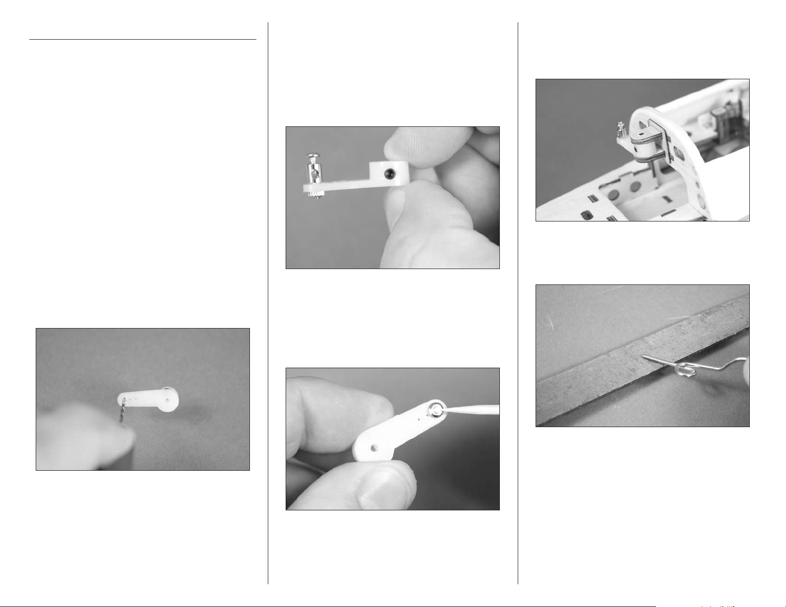
1. Use a pin vise and 5/64-inch (2mm) drill bit to
enlarge the outer hole in the steering arm.
2. Attach the pushrod connector to the outside hole
of the steering arm as shown. The washers that
come on the connector are not needed and can
be removed. Tighten the nut so it is secure on the
steering arm but is not tight. There should be a small
amount of play between the arm and the connector
and the connector should be able to rotate freely on
the arm.
3. Use a very small amount of medium CA on a
toothpick to secure the nut to the bottom of the
connector threads. Do not use thin CA for this
step as it can wick through the nut and glue the
connector to the arm. Make sure that the connector
still rotates freely in the arm after the glue is cured.
4. Install the steering arm into the bracket on the
lower section of the fire wall. The steering arm will fit
in the bracket as shown with the pushrod connector
facing the bottom of the fuselage.
5. The end of the nose gear wire may have to
be filed slightly to remove any burs or edges for
an easier fit.
11E-flite Cessna 150 Aerobat 250 ARF Assembly Manual
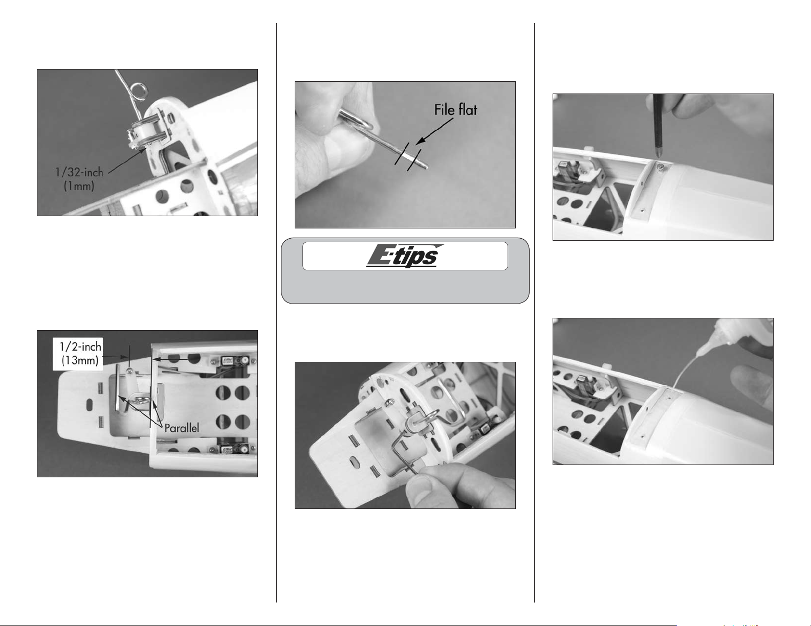
6. Slide the nose gear wire into the bracket and
steering arm. The top of the gear will protrude
through the bracket 1/32-inch (1mm).
7. Position the nose gear wire so it is parallel to the
former as shown. Position the steering arm so the
connector is 1/2-inch (13mm) from the former. Check
to make sure that 1/32-inch (1mm) of the wire is still
protruding through the top of the arm. Tighten the
screw on the steering arm so it will leave a mark on
the nose gear wire.
8. Remove the nose gear wire from the airframe.
Use a flat file to make a flat area for the screw in the
steering arm. This will help prevent the gear from
rotating when flown from rough surfaces.
Always use threadlock on metal-to-metal fasteners
to prevent them from vibrating loose.
9. Place the nose gear back into position and
tighten the screw in the steering arm using a
1.5mm hex wrench.
10. Use a #2 Phillips screwdriver to thread a 3mm x
8mm self-tapping screw into each of the holes to cut
threads in the surrounding wood plate for mounting
the main gear. Remove the screw before moving to
the next step.
11. Apply 2–3 drops of thin CA in each of the holes
to harden the surrounding wood. This will harden
the threads so the screws do not easily strip the
surrounding wood.
 Loading...