


Leader 480
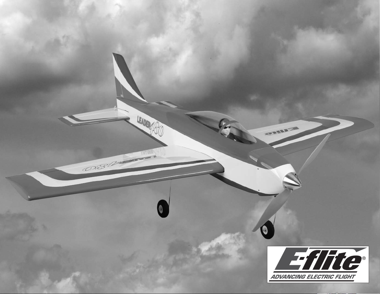
Leader 480 ARF
Assembly Manual

Notice
All instructions, warranties and other collateral
documents are subject to change at the sole
discretion of Horizon Hobby, Inc. For up-to-date
product literature, visit http://www.horizonhobby.
com and click on the support tab for this product.
Meaning of Special Language
The following terms are used throughout the product
literature to indicate various levels of potential harm
when operating this product:
This is a sophisticated hobby product and NOT a
toy. It must be operated with caution and common
sense and requires some basic mechanical
ability. Failure to operate this Product in a safe
and responsible manner could result in injury or
damage to the product or other property. This
product is not intended for use by children without
direct adult supervision. Do not attempt disassembly,
use with incompatible components or augment
product in any way without the approval of Horizon
Hobby, Inc. This manual contains instructions for
safety, operation and maintenance. It is essential to
read and follow all the instructions and warnings
in the manual, prior to assembly, setup or use, in
order to operate correctly and avoid damage or
serious injury.
PROPELLER
Keep loose items that can get entangled in the
propeller away from the prop, including loose clothing,
or other objects such as pencils and screwdrivers.
Especially keep your hands away from the propeller as
injury can occur.
BATTERIES
Notes on Lithium Polymer Batteries
When misused, lithium polymer batteries are
significantly more volatile than alkaline or Ni-Cd/
Ni-MH batteries used in RC applications. Always
follow the manufacturer’s instructions when using and
disposing of any batteries. Mishandling of Li-Po batteries
can result in fire causing serious injury and damage.
NOTICE: Procedures, which if not properly followed,
create a possibility of physical property damage
AND a little or no possibility of injury.
CAUTION: Procedures, which if not properly followed,
create the probability of physical property damage
AND a possibility of serious injury.
WARNING: Procedures, which if not properly followed,
create the probability of property damage, collateral
damage, and serious injury OR create a high
probability of superficial injury.
WARNING: Read the ENTIRE instruction
manual to become familiar with the features of the
product before operating. Failure to operate the
product correctly can result in damage to the
product, personal property and cause serious injury.
Warnings
Read and follow all instructions and safety precautions
before use. Improper use can result in fire, serious
injury and damage to property.
Age Recommendation: Not for Children under 14
years. This is not a toy.
COMPONENTS
Use only with compatible components. Should any
compatibility questions exist please refer to the product
instructions, the component instructions or contact
Horizon Hobby, Inc.
FLIGHT
Fly only in open areas to ensure safety. It is
recommended flying be done at AMA (Academy of
Model Aeronautics) approved flying sites. Consult local
laws and ordinances before choosing a location to fly
your aircraft.
SMALL PARTS
This kit includes small parts and should not be left
unattended near children as choking and serious injury
could result.
SAFETY PRECAUTIONS
• Checkallcontrolsurfacespriortoeachtakeoff.
• Donotflyyourmodelnearspectators,parkingareas
or any other area that could result in injury to people
or damage of property.
• Donotflyduringadverseweatherconditions.Poor
visibility can cause disorientation and loss of control
of your aircraft. Strong winds can cause similar
problems.
• Donottakechances.Ifatanytimeduringflightyou
observe any erratic or abnormal operation, land
immediately and do not resume flight until the cause
of the problem has been ascertained and corrected.
Safety can never be taken lightly.
• Donotflynearpowerlines.
2 E-flite Leader 480 ARF Assembly Manual
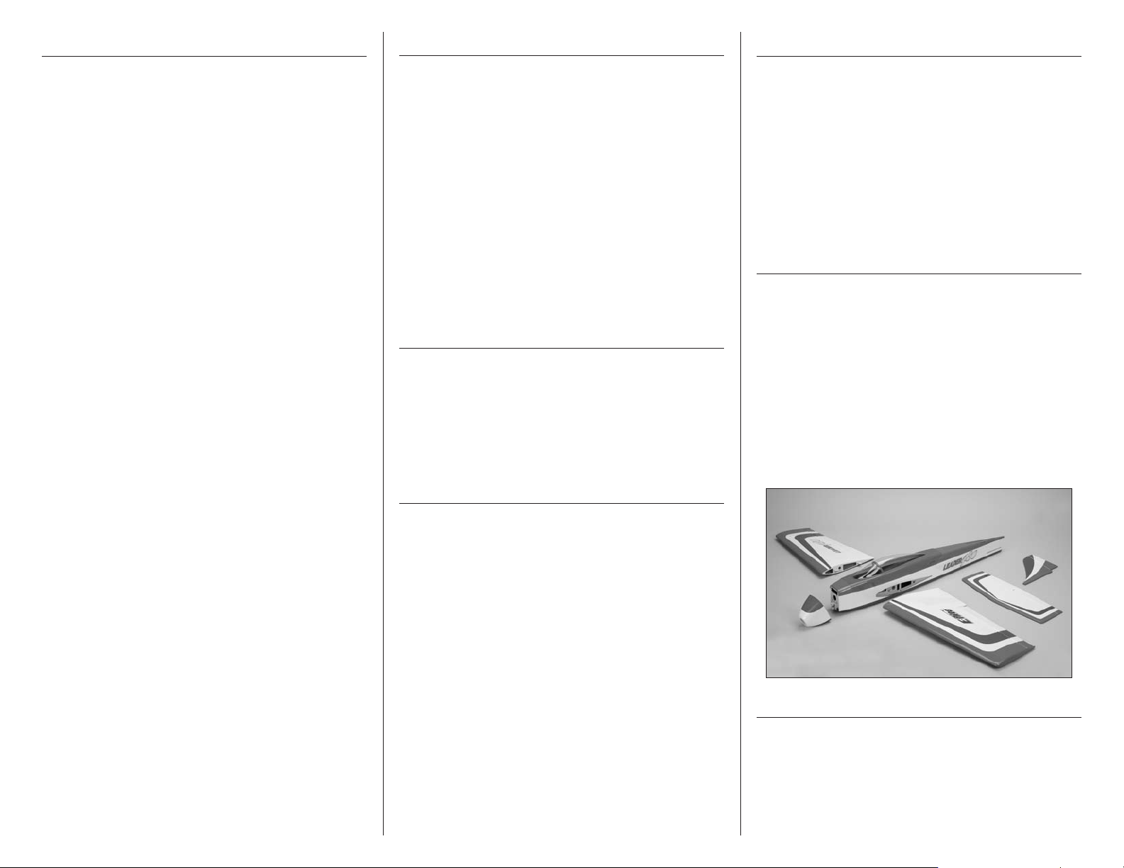
Table of Contents
Introduction
Using the Manual
Notice ......................................................................2
Meaning of Special Language ...................................2
Warnings .................................................................2
Introduction .............................................................. 3
Important Information Regarding
Warranty Information .......................................3
Specifications ...........................................................3
Using the Manual .....................................................3
Contents of Kit/Parts Layout ......................................3
Covering Colors ........................................................3
Hardware/Accessory Sizes ....................................... 4
Recommended Radio Equipment ................................4
480 Motor Setup ......................................................4
Optional Accessories ................................................4
Required Tools and Adhesives ...................................4
Before Starting Assembly ..........................................4
Hinging the Ailerons .................................................5
Aileron Servo Installation ..........................................6
Rudder and Elevator Servo Installation ....................... 8
Nose Gear Installation ............................................10
Receiver Installation................................................. 11
Motor and Speed Control Installation ....................... 12
Cowling and Spinner Installation .............................13
Main Landing Gear Installation ...............................15
Wing Installation ....................................................16
Stabilizer Installation ............................................... 17
Vertical Fin Installation ............................................18
Rudder and Elevator Installation ..............................19
Motor Battery Installation......................................... 22
Optional Pilot Installation......................................... 22
Center of Gravity .................................................... 23
Control Throws .......................................................24
Preflight ..................................................................24
Range Test Your Radio .............................................25
Flying Your Model ...................................................25
Daily Flight Checks ................................................. 26
Warranty and Repair Policy .................................... 26
Warranty Services ..................................................27
Compliance Information for the European Union ...... 27
Academy of Model Aeronautics
National Model Aircraft Safety Code ..............28
The nimble Leader 480 park flyer is a fun-to-fly
sport plane that is ideal for anyone interested in
precision aerobatics. Its light wing loading will put any
intermediate pilot at ease when flying the slow side of
the envelope. But if you really want to wring it out, its
symmetrical airfoil and classic pattern plane lines will
allow you to fly precision aerobatics with the best of
them.
Assembly is so simple, you could easily have it flightready in a single evening. Plus, it’s small enough you
can put it in the backseat or trunk of your car and fly it
most anywhere park flyers are allowed.
Important Information
Regarding Warranty Information
Please read our Warranty and Liability Limitations
section before building this product. If you as the
Purchaser or user are not prepared to accept the
liability associated with the use of this Product, you are
advised to return this Product immediately in new and
unused condition to the place of purchase.
Specifications
Wingspan: 43.0 in (1100mm)
Length: 42.4 in (1080mm)
Wing Area: 414 sq in (26.7 sq dm)
Weight with Battery: 39–41 oz (1110–1170 g)
Weight w/o Battery: 33–35 oz (935–990 g)
This manual is divided into sections to help make
assembly easier to understand, and to provide breaks
between each major section. In addition, check boxes
have been placed next to each step to keep track
of its completion. Steps with a single circle () are
performed once, while steps with two or more circles
() indicate the step will require repeating, such as
for a right or left wing panel, two servos, etc.
Remember to take your time and follow the directions.
Contents of Kit/Parts Layout
Replacement Parts
EFL300001 Fuselage
EFL300002 Wing Set
EFL300003 Tail Set
EFL300004 Cowling
EFL300005 Landing Gear Strut Set
EFL300006 Canopy Hatch
EFL300007 Main Wheel Set
EFL300008 Wing Tube
EFL300009 Hardware Package
EFL300010 Pushrod Set
Covering Colors
True Red HANU866
Deep Blue HANU873
White HANU870
3E-flite Leader 480 ARF Assembly Manual

Hardware/Accessory Sizes
Optional Accessories
Before Starting Assembly
Wheel diameter 2-in (51mm)
Wing bolts 3mm x 10mm socket
head cap screw
Recommended Radio Equipment
You will need a minimum 4-channel transmitter,
receiver and four servos. You can choose to purchase
a complete radio system. If you are using an
existing transmitter, just purchase the other required
equipment separately. We recommend the crystalfree, interference-free Spektrum™ DX6 2.4GHz DSM®
6-channel system. If using your own transmitter, we
recommend the following radio equipment.
If you own the Spektrum DX6i radio, or you are
using a different DSM2
6-channel DSMX microlite receiver and four E-flite®
DS76 servos.
Complete Radio System
SPM6610 DX6i DSMX 6CH system
Or Purchase Separately
SPMAR6115 AR6115 6CH DSMX™
EFLRDS76 DS76 Digital Servo (4)
EFLREX3L 3-inch (76mm) Servo Extension
EFLREX6L 6-inch (152mm)
™
radio, just add the AR6115
Microlite Receiver
Servo Extension (3)
480 Motor Setup
EFLA110 Power Meter
EFLC505 Intelligent 1- to 5-Cell
Balancing Charger
EFLAEC312 Charge Lead with 12-inch
Wire and Jacks, 16AWG
EFLSP175 13/4-inch Aluminum Spinner
with 4mm and 5mm Collets
EFLA156 1/9 Civilian Pilot, Blue
with Glasses
Required Tools and Adhesives
Tools & Equipment
Box wrench: 10mm Felt-tipped pen
Flat file Hex wrench: 1.5mm, 2.5mm
Low-tack tape Pin vise
Ruler Scissors
Side cutter Square
T-pins Two-sided tape
String or dental floss
Drill bit: 1/16-inch (1.5mm), 5/64-inch (2mm)
Hobby knife with #11 blade
Phillips screwdriver: #0, #1, #2
Optional Tools & Equipment
Balancing stand (optional)
Adhesives
Medium CA PAAPT02
Thin CA PAAPT08
Threadlock PAAPT42
Before beginning the assembly of your model, remove
each part from its bag for inspection. Closely inspect
the fuselage, wing panels, rudder and stabilizer for
damage. If you find any damaged or missing parts,
contact the place of purchase.
If you find any wrinkles in the covering, use a heat gun
(HAN100) and covering glove (HAN150) or covering
iron (HAN101) with a sealing iron sock (HAN141) to
remove them. Use caution while working around areas
where the colors overlap to prevent separating the
colors.
During the course of building your model we
suggest you use a soft base for the building surface.
Such things as a foam stand, large piece of
bedding foam or a thick bath towel will work well
and help protect the model from damage during
assembly. This is not shown in the instructions
to provide the greatest detail in the photos.
EFLM1515 Park 480
EFLA1040L 40-Amp Pro Lite SB
Brushless ESC
EFLB21003S30 2100mAh 3S 11.1V 30C Li-Po,
12AWG EC3
APC12060E 12 x 6E Electric Propeller
4 E-flite Leader 480 ARF Assembly Manual
Hinging the Ailerons
Required Parts
Wing panel with aileron (left and right)
Required Tools and Adhesives
Thin CA T-pins
Pin vise Drill bit: 1/16-inch (1.5mm)
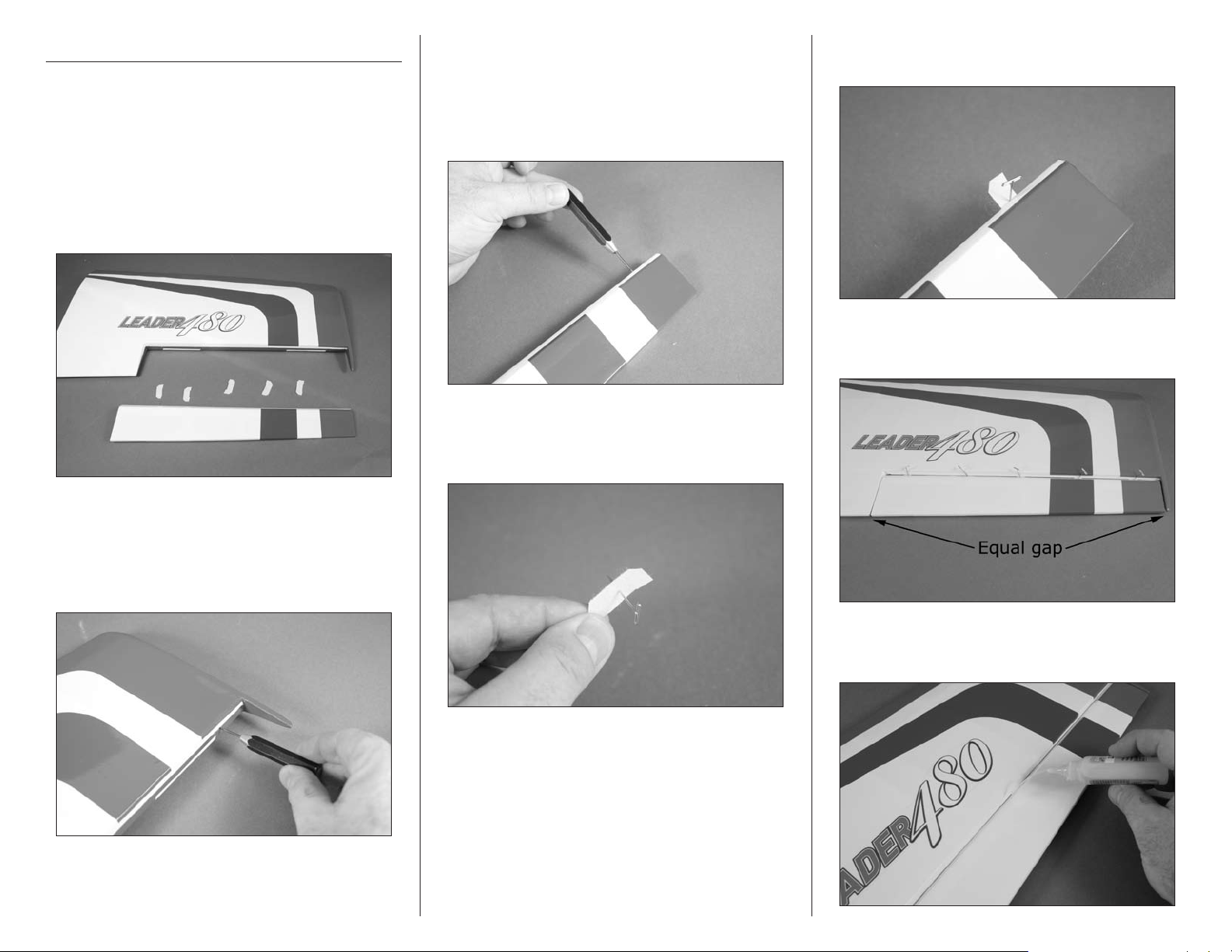
1. Separate the aileron from the wing. Set the five CA
hinges aside.
2. Use a pin vise and 1/16-inch (1.5mm) drill bit
to drill a hole in the center of each hinge slot in
the aileron to create a tunnel for the CA to wick
into. This will allow the CA to penetrate the hinge,
creating a better bond between the hinge and
surrounding wood.
3. Place a T-pin in the center of each of the five
hinges. This will center the hinges equally in the
aileron and wing when they are installed.
4. Insert the hinges in the ailerons. The T-pin will rest
on the edge of the aileron bevel.
5. Slide the aileron back into position. Center the
aileron so the gap at the ends is equal.
2. Use a pin vise and 1/16-inch (1.5mm) drill bit to
drill a hole in the center of each hinge slot in the wing
to create a tunnel for the CA to wick into. This will
allow the CA to penetrate the hinge, creating a better
bond between the hinge and surrounding wood.
6. Saturate each hinge with thin CA. Apply CA to
both the top and bottom of the hinge.
5E-flite Leader 480 ARF Assembly Manual
Do not use CA accelerator when gluing the hinges.
The CA must be allowed to soak into the hinge for the
best bond between the hinge and surrounding wood.
7. Once the CA has cured, gently pull on the control
surface and wing to make sure the hinges are glued
securely. If not, apply CA to those hinges that are not
glued and recheck.
Aileron Servo Installation
Required Parts
Transmitter Receiver
Receiver battery Servo with hardware (2)
Assembled wing panel (left and right)
Nylon control horn (2)
6-inch (152mm ) servo extension (2)
Micro screw-lock connector (2)
1mm x 180mm pushrod (2)
Required Tools and Adhesives
Side cutter Phillips screwdriver: #0, #1
Pin vise Thin CA
Medium CA String or dental floss
Threadlock Ruler
T-pins
Drill bit: 1/16-inch (1.5mm), 5/64-inch (2mm)
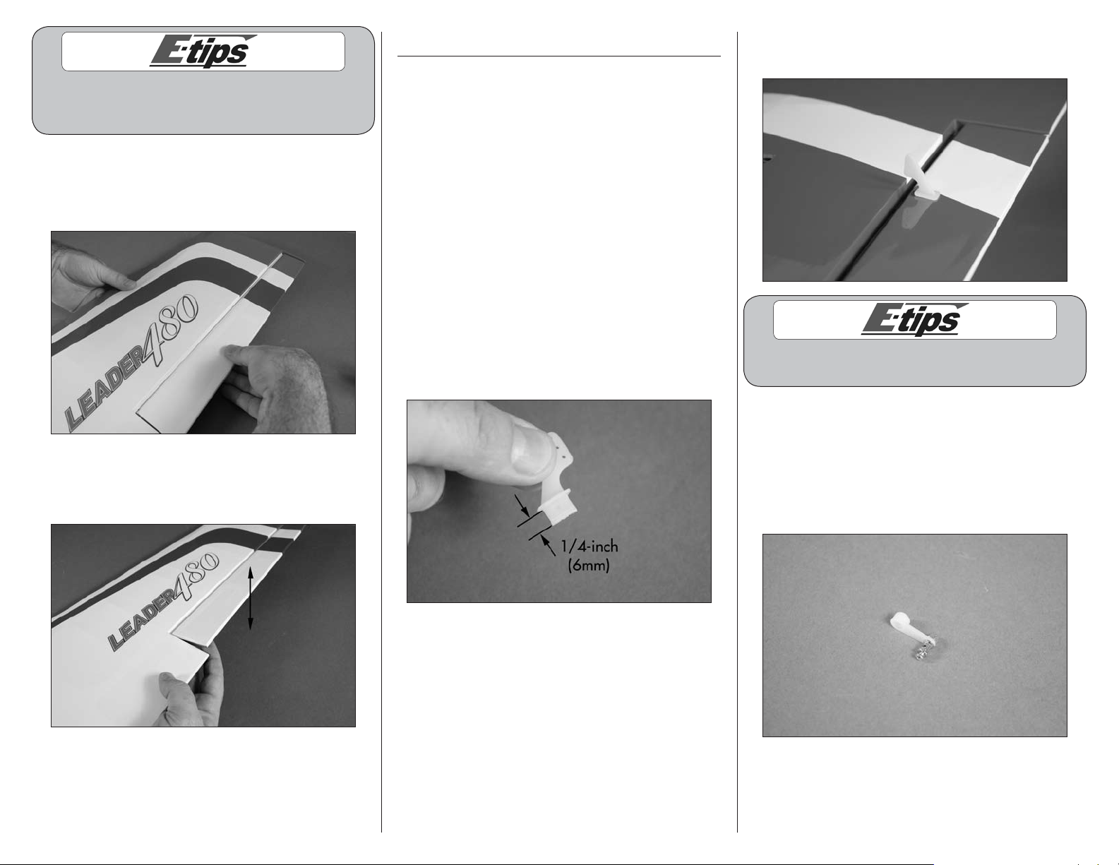
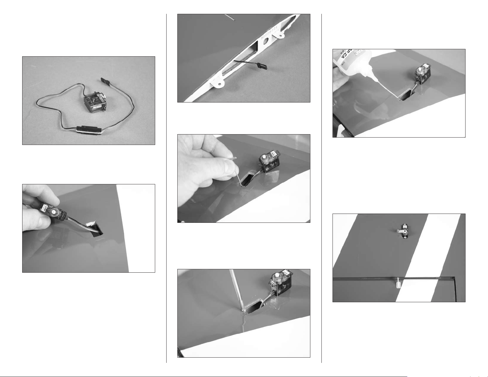
2. Use medium CA to glue the control horn in the slot
made in the bottom of the aileron.
8. Move the aileron through its range of motion
several times to break in the hinges. This will reduce
the initial load on the servo during your first flights.
9. Repeat steps 1 through 8 to hinge the
remaining aileron.
1. Use side cutters to trim the length of the control
horn to 1/4-inch (6mm) as shown.
Always use threadlock on metal-to-metal fasteners
to prevent them from vibrating loose.
3. Prepare the servo horn by enlarging the
outermost hole in a long single-sided servo horn
using a pin vise and 5/64-inch (2mm) drill bit.
Secure the micro screw-lock connector to the
servo horn using the hardware provided with the
connector. Make sure to use threadlock on the nut to
prevent it from vibrating loose.
6 E-flite Leader 480 ARF Assembly Manual
4. Connect a 6-inch (152mm) servo extension to the
servo lead. Use string of dental floss to secure the
leads so they do not accidentally disconnect inside
the wing. Use a #0 Phillips screwdriver to remove the
servo horn from the servo.
5. Insert the servo lead into the wing. Tip the wing
tip up and guide the lead out of the wing at the
wing root.
8. Apply 2–3 drops of thin CA in each of the holes
to harden the surrounding wood. This will harden
the threads so the screws do not easily strip the
surrounding wood.
6. Use a T-pin to puncture the covering, locating the
openings for the servo mounting screws.
9. Secure the servo in the wing using the screws
provided with the servo and a #1 Phillips screwdriver.
The output shaft of the servo faces toward the aileron
as shown. Center the aileron servo using the radio
system. Attach the servo horn prepared in step 3
using the screw removed in step 4 and a #0 Phillips
screwdriver. Note that the servo horn is parallel to the
aileron hinge line.
7. Use a #1 Phillips screwdriver to thread a servo
mounting screw into each of the holes to cut threads
in the surrounding wood. Remove the screw before
moving to the next step.
Note: It may be necessary to trim the servo
opening for the servo used.
7E-flite Leader 480 ARF Assembly Manual
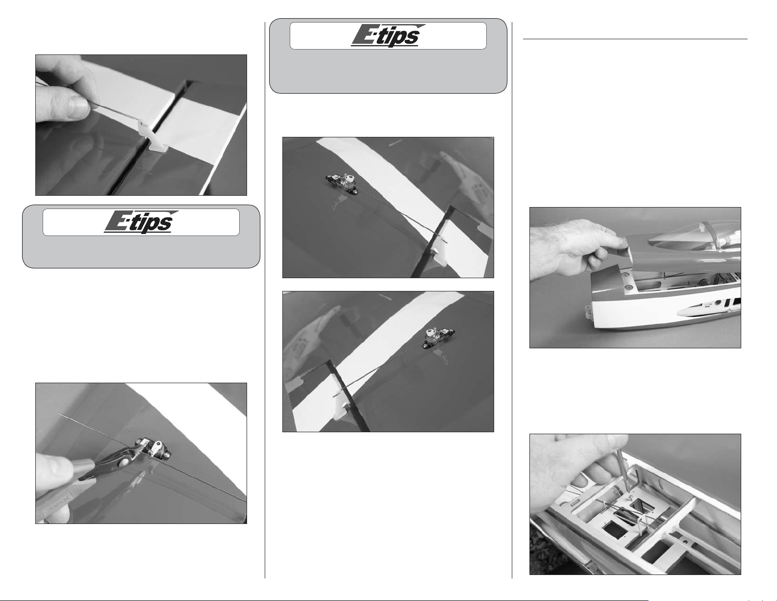
10. Pass the Z-bend in the 1mm x 180mm pushrod
through the outer hole of the aileron control horn.
Always use threadlock on metal-to-metal fasteners
to prevent them from vibrating loose.
11. The pushrod wire will pass through the hole in
the micro screw-lock connector. With the aileron
and aileron servo centered, use side cutters to
trim the pushrod so it is 1/4 inch (6mm) past the
connector as shown. Pass pushrod through micro
screw-lock connector. Use a #1 Phillips screwdriver
to tighten the screw in the connector to secure the
pushrod wire.
Use a small piece of low-tack tape to hold the aileron
in position when installing the linkage. Remove
the tape once the linkage has been installed.
12. Repeat steps 1 through 11 to install the remaining
aileron servo and pushrod.
Rudder and Elevator Servo Installation
Required Parts
Fuselage Servo with hardware (2)
Transmitter Receiver
Receiver battery Micro screw-lock connector (3)
Required Tools and Adhesives
Pin vise Phillips screwdriver: #0, #1
Thin CA Drill bit: 5/64-inch (2mm)
Threadlock
1. Remove the canopy from the fuselage. Lift the
canopy at the front to disconnect the magnets. The rear
is held in position using tabs that key into the fuselage.
2. Use a #1 Phillips screwdriver to thread a servo
mounting screw into each of the holes to cut threads
in the surrounding wood. Remove the screw before
moving to the next step. Prepare all four mounting
holes at this time.
8 E-flite Leader 480 ARF Assembly Manual
3. Apply 2–3 drops of thin CA in each of the holes
to harden the surrounding wood. This will harden
the threads so the screws do not easily strip the
surrounding wood. Prepare all four mounting holes
at this time.
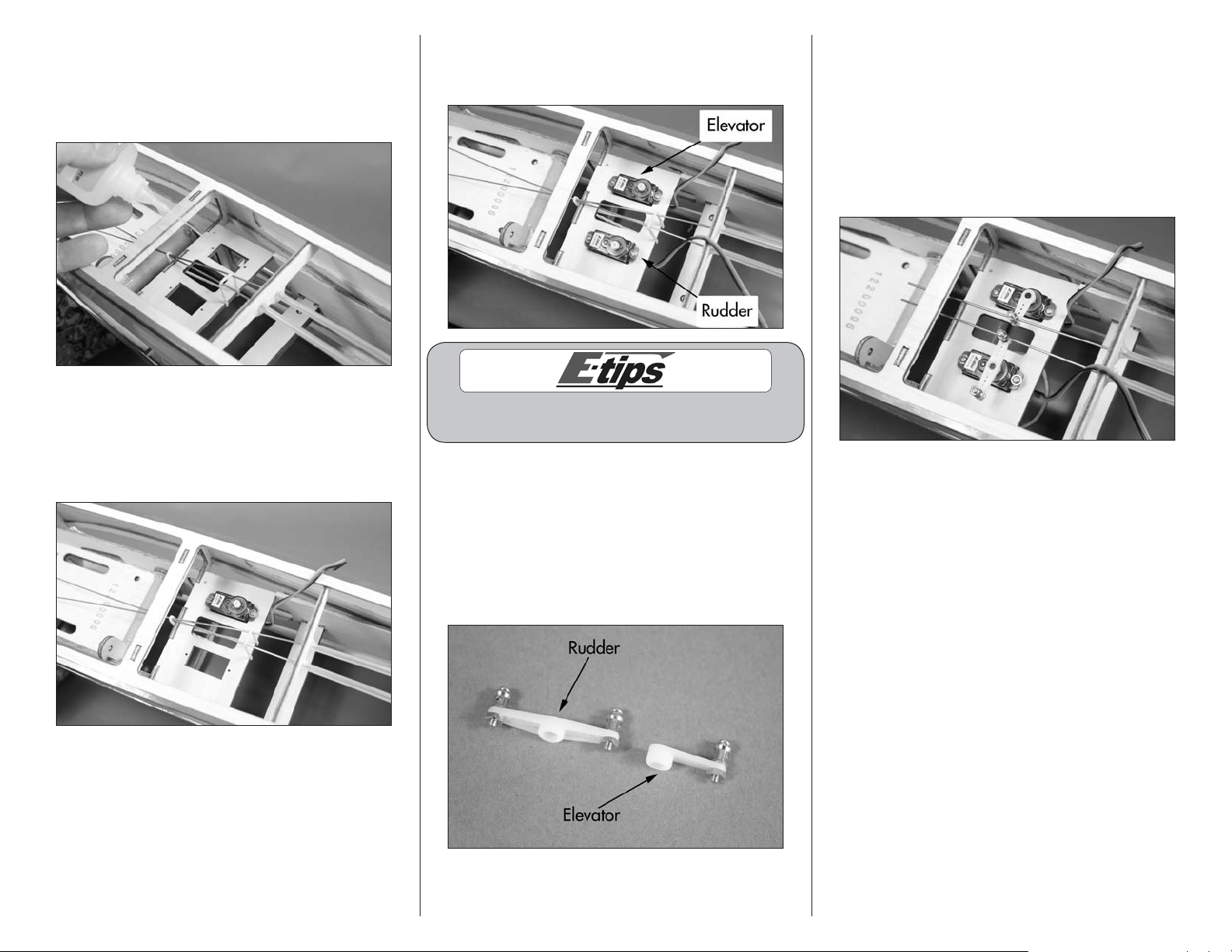
5. Repeat step 4 to install the rudder servo in the
fuselage. The output of the rudder servo faces the rear
of the fuselage when installed.
7. Use the radio system to center the rudder and
elevator servos. Attach the servo horns prepared
in step 6 on the rudder and elevator servos using
the screw previously removed from the servos and
a #0 Phillips screwdriver. Remove the rubber band
that holds the pushrod in the fuselage. Pass the
pushrod through the connectors and tighten the
screws to prevent the pushrod from falling out of
the fuselage accidentally.
4. Secure the elevator servo in the fuselage using
the screws provided with the servo and a #1 Phillips
screwdriver. The output shaft of the servo faces the
rear of the fuselage when installed. Remove the servo
horn from the servo using a #0 Phillips screwdriver.
Always use threadlock on metal-to-metal fasteners
to prevent them from vibrating loose.
6. Prepare the rudder and elevator servo horns by
enlarging the outermost hole in a long single-sided
(elevator) or long double-sided (rudder) servo horn
using a pin vise and 5/64-inch (2mm) drill bit. Secure
micro screw-lock connectors to the servo horns using
the hardware provided with the connectors. Make
sure to use threadlock on the nuts to prevent them
from vibrating loose.
9E-flite Leader 480 ARF Assembly Manual
Nose Gear Installation
Required Parts
Fuselage assembly Nose wheel steering arm
51mm foam wheel Pre-formed nose gear wire
Transmitter Receiver
Receiver battery
2.5mm wheel collar with setscrew (2)
1mm x 445mm pushrod with guide tube
Required Tools and Adhesives
Thin CA Phillips screwdriver: #2
Flat file Hex wrench: 1.5mm
Threadlock Side cutter
Sandpaper
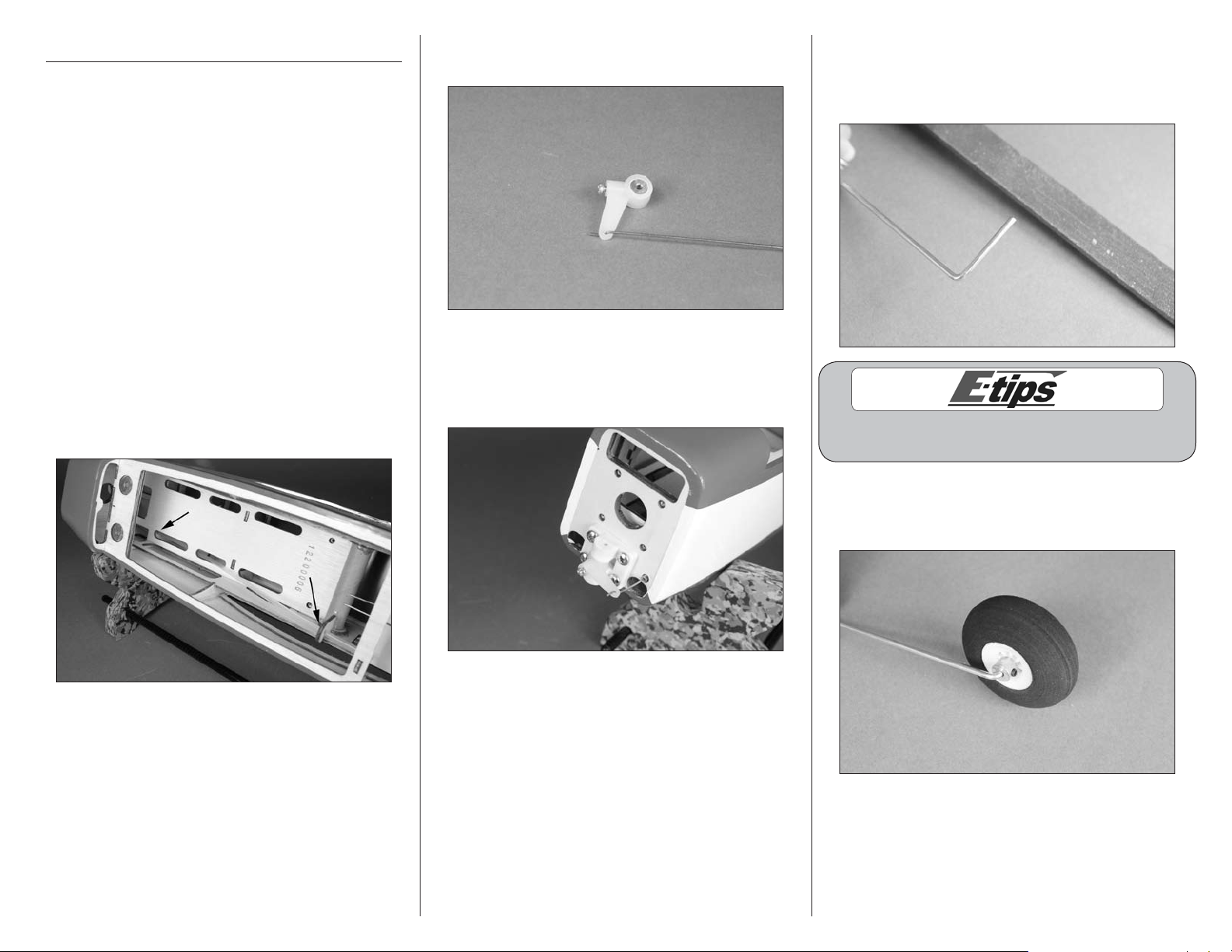
2. Insert the Z-bend of the pushrod wire into the nose
gear steering arm as shown.
4. Use a flat file to make a 1/4-inch (6mm) wide flat
on the bottom of the nose gear wire. This will provide
a place to tighten the setscrew when the wheel collar
is installed.
1. Slide the pushrod guide tube in the fuselage as
shown. Use sandpaper to scuff the tube where it
passes the mounts in the fuselage so the CA will
adhere to the tube. The end of the tube will protrude
from the fuselage by 1/32-inch (1mm) use thin CA to
glue the tube in the fuselage at the positions shown.
3. Slide the pushrod wire through the tube and into
the fuselage. Guide the wire through the connector on
the rudder servo horn. The steering arm will fit in the
bracket as shown.
Always use threadlock on metal-to-metal fasteners
to prevent them from vibrating loose.
5. Attach the wheel to the nose gear wire using two
2.5mm wheel collars and setscrews. Tighten the
setscrews using a 1.5mm hex wrench.
10 E-flite Leader 480 ARF Assembly Manual
 Loading...