


ARF Slick 3D 480
ALMOST-READY-TO-FLY
Instruction Manual
Bedienungsanleitung
Manuel d’utilisation
Manuale di Istruzioni

NOTICE
All instructions, warranties and other collateral documents are subject to change at the sole discretion of Horizon Hobby, LLC. For up-to-date product literature, visit horizonhobby. com and click on the support tab for this product.
Meaning of Special Language
The following terms are used throughout the product literature to indicate various levels of potential harm when operating this product:
NOTICE: Procedures, which if not properly followed, create a possibility of physical property damage AND a little or no possibility of injury.
CAUTION: Procedures, which if not properly followed, create the probability of physical property damage AND a possibility of serious injury.
WARNING: Procedures, which if not properly followed, create the probability of property damage, collateral damage, and serious injury OR create a high probability of superfi cial injury.
WARNING: Read the ENTIRE instruction manual to become familiar with the features of the product before operating. Failure to operate the product correctly can result in damage to the product, personal property and cause serious injury.
This is a sophisticated hobby product. It must be operated with caution and common sense and requires some basic mechanical ability. Failure to operate this Product in a safe and responsible manner could result in injury or damage to the product or other property. This product is not intended for use by children without direct adult supervision. Do not use with incompatible components or alter this product in any way outside of the instructions provided by Horizon Hobby, LLC. This manual contains instructions for safety, operation and maintenance. It is essential to read and follow all the instructions and warnings in the manual, prior to assembly, setup or use, in order to operate correctly and avoid damage or serious injury.
SAFETY WARNINGS AND PRECAUTIONS
Read and follow all instructions and safety precautions before use. Improper use can result in fi re, serious injury and damage to property.
Components
Use only with compatible components. Should any compatibility questions exist, please refer to the product instructions, component instructions or contact the appropriate Horizon Hobby offi ce.
Flight
Fly only in open areas to ensure safety. It is recommended fl ying be done at radio control fl ying
fi elds. Consult local ordinances before choosing a fl ying location.
Propeller
Keep loose items that can become entangled in the propeller away from the prop. This includes loose clothing or other objects such as pencils and
screwdrivers. Keep your hands away from the propeller as injury can occur.
Batteries
Always follow the manufacturer’s instructions when using and disposing of any batteries. Mishandling of Li-Po batteries can result in fi re causing serious injury and damage.
Small Parts
This kit includes small parts and should not be left unattended near children as choking and serious injury could result.
SAFE OPERATING RECOMMENDATIONS
•Inspect your model before every fl ight to ensure it is airworthy.
•Be aware of any other radio frequency user who may present an interference problem.
•Always be courteous and respectful of other users in your selected fl ight area.
•Choose an area clear of obstacles and large enough to safely accomodate your fl ying activity.
•Make sure this area is clear of friends and spectators prior to launching your aircraft.
•Be aware of other activities in the vicinity of your fl ight path that could cause potential confl ict.
•Carefully plan your fl ight path prior to launch.
•Abide by any and all established AMA National Model Aircraft Safety Code.
REGARDING MOTOR AND BATTERY SELECTION
This model has been tested using the components listed in the Power Systems section of this manual. Using components that exceed the output of the listed components may place excessive loads on the airframe. This could result in the failure of the airframe in highspeed or high-load situations.
Age Recommendation: Not for children under 14 years. This is not a toy.
USING THE MANUAL
This manual is divided into sections to help make assembly easier to understand. Boxes ( ) have been placed next to each step. These help keep track of steps that have been completed.
2 |
EFL Slick 3D 480 |

HINWEIS
Alle Anweisungen, Garantien und anderen zugehörigen Dokumente können im eigenen Ermessen von Horizon Hobby, LLC. jederzeit geändert werden. Die aktuelle Produktliteratur fi nden Sie auf horizonhobby.com unter der Registerkarte „Support“ für das betreffende Produkt.
Spezielle Bedeutungen
Die folgenden Begriffe werden in der gesamten Produktliteratur verwendet, um auf unterschiedlich hohe Gefahrenrisiken beim Betrieb dieses Produkts hinzuweisen:
HINWEIS: Wenn diese Verfahren nicht korrekt befolgt werden, können sich möglicherweise Sachschäden UND geringe oder keine Gefahr von Verletzungen ergeben.
ACHTUNG: Wenn diese Verfahren nicht korrekt befolgt werden, ergeben sich wahrscheinlich Sachschäden UND die Gefahr von schweren Verletzungen.
WARNUNG: Wenn diese Verfahren nicht korrekt befolgt werden, ergeben sich wahrscheinlich Sachschäden, Kollateralschäden und schwere Verletzungen ODER mit hoher Wahrscheinlichkeit oberfl ächliche Verletzungen.
WARNUNG: Lesen Sie die GESAMTE Bedienungsanleitung, um sich vor dem Betrieb mit den Produktfunktionen vertraut zu machen. Wird das Produkt nicht korrekt betrieben, kann dies zu Schäden am
Produkt oder persönlichem Eigentum führen oder schwere Verletzungen verursachen.
Dies ist ein hochentwickeltes Hobby-Produkt. Es muss mit Vorsicht und gesundem Menschenverstand betrieben werden und benötigt gewisse mechanische Grundfähigkeiten. Wird dieses Produkt nicht auf eine sichere und verantwortungsvolle Weise betrieben, kann dies zu Verletzungen oder Schäden am Produkt oder anderen Sachwerten führen. Dieses Produkt eignet sich nicht für die Verwendung durch Kinder ohne direkte Überwachung eines Erwachsenen. Verwenden Sie das Produkt nicht mit inkompatiblen Komponenten oder verändern es in jedweder Art ausserhalb der von Horizon Hobby, LLC. vorgegebenen Anweisungen. Diese Bedienungsanleitung enthält Anweisungen für Sicherheit, Betrieb und Wartung. Es ist unbedingt notwendig, vor Zusammenbau, Einrichtung oder Verwendung alle Anweisungen und Warnhinweise im Handbuch zu lesen und zu befolgen, damit es bestimmungsgemäß betrieben werden kann und Schäden oder schwere Verletzungen vermieden werden.
Nicht geeignet für Kinder unter 14 Jahren. Dies ist kein Spielzeug.
ÜBER DIESE ANLEITUNG
Diese Anleitung ist zur Vereinfachung des Zusammenbaues in Sektionen unterteilt. Neben den Sektionen befi nden sich Kästchen ( ) die es Ihnen leichter machen den Arbeitsschritt als erledigt abzuhaken.
WARNUNGEN UND SICHERHEITSVORKEHRUNGEN
Bitte lesen und befolgen Sie alle Anweisungen und Sichervorkehrungen vor dem Gebrauch. Falscher, nicht sachgemäßer Gebrauch kann Feuer, ernsthafte
Verletzungen und Sachbeschädigungen zur Folge haben.
Komponenten
Verwenden Sie mit dem Produkt nur kompatible Komponenten. Sollten Fragen zur Kompatibilität auftreten, lesen Sie bitte die Produktoder Bedienungsanweisung oder kontaktieren den Service von Horizon Hobby.
Fliegen
Fliegen Sie um Sicherheit garantieren zu können, nur in weiten offenen Gegenden. Wir empfehlen hier den Betrieb auf zugelassenen Modellfl ugplätzen. Bitte
beachten Sie lokale Vorschriften und Gesetze, bevor Sie einen Platz zum Fliegen wählen.
Propeller
Halten Sie lose Gegenstände die sich im Propeller verfangen können weg vom Propeller. Dieses gilt auch für Kleidung oder andere Objekte wie zum Beispiel Stifte oder Schraubendreher.
Halten Sie ihre Hände weg vom Propeller, es besteht akute Verletzungsgefahr.
Akkus
Folgen Sie immer den Herstelleranweisungen bei dem Gebrauch oder Entsorgung von Akkus. Falsche Behandlung von Li-Po Akkus kann zu Feuer mit Körperverletzungen und Sachbeschädigung führen.
Kleinteile
Dieser Baukasten beinhaltet Kleinteile und darf nicht unbeobachtet in der Nähe von Kindern gelassen werden, da die Teile verschluckt werden könnten mit ernsthaften Verletzung zur Folge.
EMPFEHLUNGEN ZUM SICHEREN BETRIEB
•Überprüfen Sie zur Flugtauglichkeit ihr Modell vor jedem Flug.
•Beachten Sie andere Piloten deren Sendefrequenzen ihre Frequenz stören könnte.
•Begegnen Sie anderen Piloten in ihrem Fluggebiet immer höfl ich und respektvoll.
•Wählen Sie ein Fluggebiet, dass frei von Hindernissen und groß genug ist.
•Stellen Sie vor dem Start sicher, dass die Fläche frei von Freunden und Zuschauern ist.
•Beobachten Sie den Luftraum und andere Flugzeuge/ Objekte die ihren Flugweg kreuzen und zu einem Konfl ikt führen könnten.
•Planen Sie sorgfältig ihren Flugweg vor dem Start.
MOTORUND AKKUAUSWAHL
Dieses Modell wurde mit den Komponenten getestet die in dem Kapitel Antriebe aufgeführt sind. Sollten Sie Komponenten verwenden die nicht aufgeführt sind, könnte dieses zu einer erheblichen Belastung des Rumpfes führen. Das könnte zu einem Versagen des Rumpfes bei hohen Geschwindigkeiten oder bei starken Belastungen führen.
EFL Slick 3D 480 |
3 |

REMARQUE
La totalité des instructions, garanties et autres documents est sujette à modifi cation à la seule discrétion d’Horizon Hobby, LLC. Pour obtenir la documentation à jour, rendez-vous sur le site horizonhobby.com et cliquez sur l’onglet de support de ce produit.
Signifi cation de certains termes spécifi ques
Les termes suivants sont utilisés dans l’ensemble du manuel pour indiquer différents niveaux de danger lors de l’utilisation de ce produit:
REMARQUE: Procédures qui, si elles ne sont pas suivies correctement, peuvent entraîner des dégâts matériels ET éventuellement un faible risque de blessures.
ATTENTION: Procédures qui, si elles ne sont pas suivies correctement, peuvent entraîner des dégâts matériels ET des blessures graves.
AVERTISSEMENT: Procédures qui, si elles ne sont pas suivies correctement, peuvent entraîner des dégâts matériels et des blessures graves OU engendrer une probabilité élevée de blessure superfi cielle.
AVERTISSEMENT: Lisez la TOTALITÉ du manuel d’utilisation afi n de vous familiariser avec les caractéristiques du produit avant de le faire fonctionner. Une utilisation incorrecte du produit peut entraîner
sa détérioration, ainsi que des risques de dégâts matériels, voire de blessures graves.
Ceci est un produit de loisirs sophistiqué. Il doit être manipulé avec prudence et bon sens et requiert des aptitudes de base en mécanique. Toute utilisation irresponsable de ce produit ne respectant pas les principes de sécurité peut provoquer des blessures, entraîner des dégâts matériels et endommager le produit. Ce produit n’est pas destiné à être utilisé par des enfants sans la surveillance directe d’un adulte. N’essayez pas de modifi er ou d’utiliser ce produit avec des composants incompatibles hors des instructions fournies par Horizon Hobby, LLC. Ce manuel comporte des instructions relatives à la sécurité, au fonctionnement et à l’entretien. Il est capital de lire et de respecter la totalité des instructions et avertissements du manuel avant l’assemblage, le réglage et l’utilisation, ceci afi n de manipuler correctement l’appareil et d’éviter tout dégât matériel ou toute blessure grave.
14 ans et plus. Ceci n’est pas un jouet.
UTILISATION DU MANUEL
Ce manuel est divisé en sections pour vous aider à comprendre plus facilement l’assemblage. Des cases ( ) ont été placées à chaque étape. Cela vous permet d’avoir un suivi des étapes déjà effectuées.
AVERTISSEMENTS RELATIFS À LA SÉCURITÉ
Lisez et suivez toutes les instructions relatives à la sécurité avant utilisation. Une utilisation inappropriée peut entraîner un incendie, de graves blessures et des dégâts matériels.
Composants
Utilisez uniquement des composants compatibles. Si vous avez des questions concernant la compatibilité, référez-vous à ce manuel ou contactez le service technique Horizon Hobby.
Le vol
Volez uniquement dans des zones dégagées pour un maximum de sécurité. Il est recommandé d’utiliser les pistes des clubs d’aéromodélisme. Consultez votre mairie pour connaître les sites autorisés.
L’hélice
Gardez éloignés tous les éléments qui pourraient être attrapés par l’hélice. Cela inclut les vêtements larges ou les objets comme des outils par exemple. Gardez toujours vos mains à distance pour éviter tout cas de blessures.
Les batteries
Suivez toujours les instructions du fabricant de vos batteries. Une mauvaise manipulation d’une batterie LiPo peut entraîner un incendie causant de graves dégâts matériels et des blessures corporelles.
Petites pièces
Ce kit contient des petites pièces qui ne doivent pas être laissées à la portée des enfants, ces pièces sont dangereuses pour eux et peuvent entraîner de graves blessures.
CONSIGNES DE SÉCURITÉ
CONCERNANT L’UTILISATION
•Inspectez votre modèle avant chaque vol.
•Surveillez les fréquences utilisées à proximité.
•Soyez toujours courtois et respectueux des autres utilisateurs de la zone de vol.
•Choisissez une zone dégagée de tout obstacle et suffi samment grande pour voler en toute sécurité.
•Contrôlez que la zone est libre de spectateurs avant de lancer votre modèle.
•Soyez conscient des autres activités aux alentours de votre vol, pour éviter tout confl it potentiel.
•Planifi ez votre vol avant de le commencer.
SÉLECTION DE LA BATTERIE ET DU MOTEUR
Ce modèle a été testé avec les éléments cités dans la section relative à la motorisation de ce manuel. L’utilisation d’éléments supérieurs à ceux présentés dans ce manuel peuvent générer des contraintes trop importantes sur la structure. Cela peut causer une rupture de la structure à haute vitesse ou lors de ressources.
4 |
EFL Slick 3D 480 |

AVVISO
Tutte le istruzioni, le garanzie e gli altri documenti pertinenti sono soggetti a cambiamenti a totale discrezione di Horizon Hobby, LLC. Per una documentazione aggiornata sul prodotto, visitare il sito www.horizonhobby.com e fare clic sulla sezione Support per questo prodotto.
Signifi cato dei termini particolari
In tutta la documentazione relativa al prodotto sono utilizzati i seguenti termini per indicare vari livelli di potenziale pericolo durante il funzionamento:
AVVISO: Procedure che, se non sono seguite correttamente, possono creare danni materiali E nessuna o scarsa possibilità di lesioni.
ATTENZIONE: Procedure che, se non sono seguite correttamente, possono creare danni materiali E possibili gravi lesioni.
AVVERTENZA: Procedure che, se non debitamente seguite, espongono alla possibilità di danni alla proprietà fi sica o possono omportare un’elevata possibilità di provocare ferite superfi ciali. Ulteriori precauzioni per la sicurezza e avvertenze.
AVVERTENZA: Leggere TUTTO il manuale di istruzioni e prendere familiarità con le caratteristiche del prodotto, prima di farlo funzionare. Un utilizzo scorretto del prodotto può causare danni al prodotto stesso,
alle persone o alle cose, provocando gravi lesioni.
Questo è un prodotto di hobbistica sofi sticato e NON un giocattolo. È necessario farlo funzionare con cautela e responsabilità e avere conoscenze basilari di meccanica. Se questo prodotto non è utilizzato in maniera sicura e responsabile potrebbero verifi carsi lesioni o danni al prodotto stesso o ad altre proprietà. Non è un prodotto adatto a essere utilizzato dai bambini senza la diretta supervisione di un adulto. Non usare componenti non compatibili o alterare il prodotto in nessuna maniera al di fuori delle istruzioni fornite da Horizon Hobby, LLC.
Questo manuale contiene le istruzioni per un funzionamento e una manutenzione sicuri. È fondamentale leggere e seguire tutte le istruzioni e le avvertenze del manuale prima di montare, confi gurare o far funzionare il Prodotto, al fi ne di utilizzarlo correttamente e di evitare danni o lesioni gravi.
AVVERTIMENTI E PRECAUZIONI PER LA SICUREZZA
Prima dell’uso leggere attentamente tutte le istruzioni e le precauzioni per la sicurezza. In caso contrario si potrebbero procurare incendi, danni o ferite.
Componenti
Usare solo componenti compatibili. Se ci fossero dubbi riguardo alla compatibilità, è opportuno far riferimento alle istruzioni relative al prodotto o ai componenti oppure rivolgersi al reparto Horizon Hobby di competenza.
Volo
Per sicurezza volare solo in aree molto ampie. Meglio se si va su campi volo autorizzati per modellismo. Consultare le ordinanze locali prima di scegliere una ubicazione.
Elica
Tenere gli oggetti liberi (vestiti, penne, cacciaviti, ecc.) lontano dall’elica, prima che vi restino impigliati. Bisogna fare attenzione anche con le mani perché c’è il rischio di ferirsi anche gravemente.
Batterie
Quando si maneggiano o si utilizzano le batterie, bisogna attenersi alle istruzioni del costruttore; il rischio è di procurare incendi, specialmente con le batterie Li-Po, con danni e ferite serie.
Piccole parti
Questo kit comprende delle parti di piccole dimensioni e non lo si può lasciare incustodito se c’è la presenza di bambini che li possono inghiottire e rimanere soffocati o intossicati.
RACCOMANDAZIONI PER OPERARE IN SICUREZZA
•Controllare attentamente il modello prima di ogni volo per accertarsi che sia idoneo.
•Essere consapevoli che un altro utente della frequenza in uso, potrebbe procurare delle interferenze.
•Essere sempre cortesi e rispettosi nei confronti degli altri utilizzatori dell’area in cui ci si trova.
•Scegliere un’area libera da ostacoli e abbastanza ampia da permettere lo svolgimento del volo in sicurezza.
•Prima del volo verifi care che l’area sia libera da amici e spettatori.
•Stare attenti alle altre attività che si svolgono in vicinanza della vostra traiettoria di volo, per evitare possibili confl itti.
•Pianifi care attentamente il volo prima di lanciare il modello.
•Rispettare sempre scrupolosamente le regole stabilite dall’associazione locale.
RIGUARDO ALLA SCELTA DI MOTORE E BATTERIA
Questo modello è stato provato usando i componenti elencati nella sezione “Sistema di propulsione” di questo manuale. Usando componenti all’infuori di quell’elenco, si potrebbe dare un carico eccessivo alla struttura. Questo potrebbe causare delle rotture ad alta velocità e in situazioni con cariche elevati.
Almeno 14 anni. Non è un giocattolo.
COME USARE IL MANUALE
Questo manuale è diviso in sezioni per rendere più facile la comprensione del montaggio. Vicino ad ogni passo sono stati posti dei piccoli quadrati ( ) per aiutare a tenere traccia delle cose fatte e di quelle da fare.
EFL Slick 3D 480 |
5 |
SPECIFICATIONS•SPEZIFIKATIONEN•
SPÉCIFICATIONS•SPECIFICHE
42.1 in (1070mm)
390 sq in (25.1 dm2)
39.5 in (1000mm)
37.5–39.7 oz (1125–1063 g)
Electric Power Power: Power 480 Brushless Elektro Antrieb Power: Power 480 Brushless Moteur électrique (EP): Power 480 Brushless Motore elettrico: Power 480 Brushless
4-channel (or greater) with 4 servos
4-Kanal (oder größer) mit 4 Servos
4 voies (ou plus) avec 4 servos a 4 canali (o più) con 4 servo
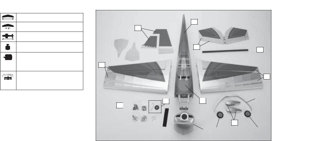
LARGE PARTS LAYOUT•BAUTEILE (OHNE KLEINTEILE)•GRANDES PIÈCES•SCHEMA DEI COMPONENTI GRANDI
1
3
3
 7
7
2
2
|
|
|
|
8 |
|
|
4 |
||
8 |
|
|
||
|
|
|
9 
6
5 |
|
10 |
|
10 |
|
|
|
|
|
6 |
EFL Slick 3D 480 |

REPLACEMENT |
PARTS•ERSATZTEILE•PIÈCES DE RECHANGE•PEZZI DI RICAMBIO |
|
|
||
|
Part |
English |
Deutsch |
Français |
Italiano |
|
|
|
|
|
|
1. |
EFL286501 |
Fuselage with Hatch |
Rumpf mit Haube |
Fuselage avec capot |
Fusoliera con portello |
|
|
|
|
|
|
2. |
EFL286502 |
Wing Set with Ailerons |
Tragfl ächenset mit Querruder |
Ailes avec ailerons |
Set ala con alettoni |
|
|
|
|
|
|
3. |
EFL286503 |
Tail Set |
Heck |
Empennages |
Set coda |
|
|
|
|
|
|
4. |
EFL286504 |
Hatch |
Haube |
Trappe supérieure |
Portello |
|
|
|
|
|
|
5. |
EFL286505 |
Cowling |
Motorhaube |
Capot moteur |
Carenatura |
|
|
|
|
|
|
6. |
EFL286506 |
Wheel Pants |
Radverkleidung |
Carénage de roue |
Copriruote |
|
|
|
|
|
|
7. |
EFL286507 |
Wing Tube 13mm x 390mm |
Tragfl ächenverbinder 13mm x 390mm |
Clé d’aile 13mm x 390mm |
Tubo dell’ala 13mm x 390mm |
|
|
|
|
|
|
8. |
EFL286508 |
Landing Gear Set with Tail Wheel Wire |
Fahrwerk mit Spornrad |
Jambes de train principal avec roulette de queue |
Set carrello con gamba ruotino coda |
|
|
|
|
|
|
9. |
EFL286509 |
Pushrod Set |
Gestänge / Anlenkungen Set |
Jeu de tringleries |
Set dell’asta di spinta |
|
|
|
|
|
|
10. |
EFL286510 |
Wheel Set |
Räder Set |
Set de roues |
Set ruote |
|
|
|
|
||
SMALL PARTS (NOT SHOWN)•KLEINTEILE (NICHT ABGEBILDET)•PETITES PIÈCES (NON REPRÉSENTÉES)•PARTI DI PICCOLE DIMENSIONI (NON MOSTRATE) |
|||||
EFL286511 |
Decal Sheet |
Dekorbögen |
Planche de décoration |
Foglio con decalcomanie |
|
|
|
||||
REQUIRED RADIO EQUIPMENT•ERFORDERLICHE RC AUSRÜSTUNG•EQUIPEMENT RADIO REQUIS•APPARECCHIATURE RADIO |
|
||||
SPMAR636 |
AR636 AS3X® Receiver |
AR636 AS3X Empfänger |
Récepteur AR636 AS3X |
AR636 AS3X Ricevitore |
|
SPMSA3030 (4) |
A3030 Sub-Micro Digital High Torque |
A3030 Sub-Micro Digital High Torque |
Sub Micro servo digital A3030 couple élevé |
A3030 Servocomando Sub-Micro Digitale |
|
|
|
Aircraft Servo |
Aircraft Servo |
|
High Torque per aerei |
|
|
|
|
|
|
SPMA3058 |
Standard Y-Harness, 6-inch |
Spektrum Hochleistungs Y-Servokabel |
Câble Y standard, 152mm |
Collegamento a Y standard, 152mm |
|
|
|
|
|
|
|
SPMA3053 (2) |
Standard Servo Extension, 12-inch |
Spektrum Servokabelverlängerung 300mm |
Rallonge servo standard, 300mm |
Prolunga standard per servo, 300mm |
|
|
|
|
|||
POWER SYSTEM•ANTRIEB•MOTORISATION•SISTEMA PROPULSIVO |
|
|
|||
EFLM1505 |
Power 480 Brushless Outrunner Motor, 1020Kv |
Power 480 Brushless Außenläufer Motor, 1020Kv |
Moteur Power 480 brushless à cage |
Power 480 motore brushless a cassa |
|
|
|
|
|
tournante, 1020Kv |
rotante, 1020Kv |
|
|
|
|
|
|
EFLA1040LB |
40-Amp Lite Pro SB Brushless ESC (V2) |
40A Lite Pro SB Brushless ESC (V2) |
Contrôleur brushless 40A Lite Pro (V2) |
40-Amp Lite Pro SB Brushless ESC (V2) |
|
|
|
|
|
|
|
EFLB22003S30 |
2200mAh 3S 11.1V 30C Li-Po |
2200mAh 3S 11.1V 30C Li-Po |
Batterie Li-Po 3S 11.1V 2200mA |
2200mAh 3S 11.1V 30C Li-Po |
|
|
|
|
|
|
|
APC12006E |
Electric Propeller, 12 x 6 |
Elektro Propeller, 12 x 6 |
Hélice électrique, 12 x 6 |
Elica elettrica sottile, 12 x 6 |
|
|
|
|
|
|
|
EFLSP200 |
2 inch Aluminum Spinner with 4mm & 5mm Collets |
Aluminium Spinner 2 inch mit 4 + 5mm Mitnehmer |
Cône aluminium 2” avec adaptateurs 4 et 5mm |
Ogiva alluminio 50mm con adattatori 4mm e 5mm |
|
|
|
|
|||
OPTIONAL ITEMS•OPTIONALE TEILE•ELÉMENTS OPTIONNELS•ARTICOLI OPZIONALI |
|
|
|||
EFLA152 |
1/9 Aerobatic Pilot-Blue |
1/9 Aerobatik Pilot-Blau |
Pilote acrobatique bleu échelle 1/9 |
Pilota blu acrobatico 1/9 |
|
|
|
|
|
|
|
EFLA110 |
Power Meter |
E-fl ite Lastmessgerät |
Wattmètre |
Misuratore di potenza |
|
|
|
|
|
|
|
DYNC2015 |
Prophet™ Precept™ 80W LCD AC/DC |
Prophet Precept 80W LCD AC/DC Ladegerät |
Chargeur Prophet Precept 80W LCD AC/DC |
Caricabatterie Prophet Precept 80W LCD AC/DC |
|
|
|
Battery Charger |
|
|
|
|
|
|
|
|
|
EFL Slick 3D 480 |
|
|
|
7 |
|

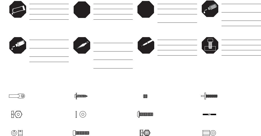
REQUIRED ADHESIVES•ERFORDERLICHE KLEBSTOFFE•TYPES DE COLLES•ADESIVI NECESSARI |
|
|||
Part |
English |
Deutsch |
Français |
Italiano |
|
|
|
|
|
PAAPT09 |
Thin CA |
Sekundenkleber dünnfl üssig |
Colle cyano fi ne |
Sottile CA |
|
|
|
|
|
PAAPT03 |
Medium CA |
Sekundenkleber mittel |
Colle cyano moyenne |
Medio CA |
|
|
|
|
|
PAAPT15 |
Zip Kicker Aerosol, 2 oz |
Zip Kicker Aerosol, 2 oz |
Accélérateur Zip Kicker, 59ml |
Spray Zip Kicker, 60g |
|
|
|
|
|
PAAPT35 |
15-Minute Epoxy |
15 Minuten Epoxy |
Époxy 15 minutes |
Colla epoxy 15 minuti |
|
|
|
|
|
PAAPT42 |
Threadlock |
Schraubensicherungslack |
Frein-fi let |
Frenafi letti |
REQUIRED TOOLS•BENÖTIGTES WERKZEUG•OUTILS REQUIS•ATTREZZI NECESSARI
English |
Deutsch |
Français |
Italiano |
Drill bit: 1/16-inch, 5/64-inch |
Bohrer: 1,5 mm, 2mm |
Foret : 1,5 mm, 2mm |
Punte per trapano: 1,5 mm, 2mm |
|
|
|
|
Felt-tipped pen |
Faserstift |
Feutre fi n effaçable |
Pennarello |
|
|
|
|
Hemostat |
Klemme |
Pince Hemostat |
Pinzetta |
|
|
|
|
Hex wrench: 1.5mm, 3/32-inch, 2.5mm |
Inbusschlüssel: 1,5mm, 3/32-inch, 2,5mm |
Tournevis hexagonal : 1,5mm, 3/32-inch, 2,5mm |
Chiave esag.: 1,5mm, 3/32-inch, 2,5mm |
|
|
|
|
Hobby and craft square |
Rechteck |
Equerre de modélisme |
Riga a squadra |
|
|
|
|
Hobby knife: #11 blade |
Hobbymesser mit # 11 Klinge |
Couteau : Lame numéro 11 |
Taglierino: #11 lama |
|
|
|
|
Low-tack tape |
Klebeband m. geringer Klebekraft |
Adhésif de masquage |
Nastro a bassa aderenza |
|
|
|
|
Nut driver: 4mm, 5.5mm |
Steckschlüssel. 4mm, 5,5mm |
Clés à douilles : 4mm, 5,5mm |
Chiave per dadi: 4mm, 5,5mm |
|
|
|
|
Open end wrench: 8mm, 7/16-inch |
Maulschlüssel: 8mm, 7/16-inch |
Clé plate ouverte : 8mm, 7/16-inch |
Chiave aperta: 8mm, 7/16-inch |
|
|
|
|
Pencil |
Stift |
Crayon à papier |
Matita |
|
|
|
|
Phillips screwdriver: #1 |
Phillips Schraubendreher: #1 |
Tournevis cruciforme: #1 |
Cacciavite a croce: #1 |
|
|
|
|
Pin vise |
Handbohrer |
Porte-forets |
Trapano manuale |
|
|
|
|
Pliers |
Zange |
Pince |
Pinze |
|
|
|
|
Ruler (Metric and English) |
Lineal (Metrisch und English) |
Réglet (Métrique et Anglais) |
Righello (Sistema metrico e inglese) |
|
|
|
|
Sandpaper (220-320 Grit) |
Schleifpapier |
Papier de verre |
Carta vetrata (Grana 220-320) |
|
|
|
|
Scissors |
Schere |
Ciseaux |
Forbici |
|
|
|
|
Side cutters |
Seitenschneider |
Pince coupante |
Lama laterale |
|
|
|
|
T-pins |
T- Nadeln |
Epingles |
Spilli a T |
|
|
|
|
Toothpicks |
Zahnstocher |
Cure dents |
Stuzzicadenti |
|
|
|
|
Two-sided tape |
Doppelseitiges Klebeband |
Adhésif double-face |
Nastro biadesivo |
|
|
|
|
8 |
EFL Slick 3D 480 |
ASSEMBLY SYMBOL GUIDE•MONTAGE SYMBOLE•GUIDE DES SYMBOLES POUR ASSEMBLAGE•GUIDA AI SIMBOLI DI ASSEMBLAGGIO
Apply threadlock
Schraubensicherungslack verwenden
Utilisez du frein fi let
Applicare fuido threadlock
Use thin CA
Dünnfl üssigen
Sekundenkleber verwenden
Utilisez de la colle cyanoacrylate fi ne
Usare colla ciano acrilica fi ne
L R
L R
Assemble right and left |
|
Use 15-minute epoxy |
Use medium CA |
|
Links und rechts montieren |
15 |
Verwenden Sie 15 Minuten Epoxy |
Mittelfl üssigen |
|
Assemblez à droite et à gauche |
Utilisez de l’époxy 15 minutes |
Sekundenkleber verwenden |
||
Utilisez de la colle |
||||
Assemblare destra e sinistra |
|
Usare una resina epossidica con |
||
|
cyanoacrylate moyenne |
|||
|
|
indurimento di 15 minuti |
||
|
|
|
||
|
|
|
Usare colla ciano acrilica media |
|
Use hobby knife with |
|
Use a felt-tipped pen |
Attach temporarily |
|
#11 blade |
|
Verwenden Sie einen Faserstift |
Vorübergehend anbringen |
|
|
|
|||
Verwenden Sie ein Hobbymesser mit |
|
Utilisez un feutre fi n effaçable |
Attachez temporairement |
|
# 11 Klinge |
|
|||
|
|
|
||
Utilisez un Couteau: |
|
Usare un pennarello |
Attaccare temporaneamente |
|
|
|
|
Lame numéro 11
Usare taglierino per hobbistica con lama numero 11
FASTENERS•VERBINDUNGSELEMENTE•VISSERIE•ELEMENTI DI FISSAGGIO
Ball Link |
Self-Tapping Washer-Head Screw |
Setscrew |
Nylon Wing Bolt |
Kugelgelenk |
Schraube mit Unterlegscheibenkopf |
Madenschraube |
Tragfl ächenbolzen |
Articulation à rotule |
Vis auto-taraudeuse épaulée |
Vis sans tête |
Vis nylon de fi xation d’aile |
Ball Link |
Vite autofi lettante fl angiata |
Set di viti |
Vite nylon per ali |
Hex Nut |
Flat Washer |
Machine screw |
Threaded rod |
Sechskantmutter |
Unterlegscheibe |
Maschinenschraube |
Gewindestange |
Ecrou hexagonal |
Rondelle plate |
Vis métal |
Tige fi letée |
Dado esagonale |
Rondella piatta |
Vite per metallo |
Barra fi lettata |
Wheel Collar |
Socket Head Cap Screw |
Lock Nut |
Aluminum Spacer |
Stellring |
Inbusschraube |
Stopmutter |
Aluminium Distanzstück |
Bague d’arrêt |
Vis BTR |
Ecrou auto-freiné |
Entretoise en aluminium |
Collare ruota |
Vite a brugola |
Dado di bloccaggio |
Distanziale in alluminio |
EFL Slick 3D 480 |
9 |

BEFORE STARTING ASSEMBLY
•Remove parts from bag.
•Inspect fuselage, wing panels, rudder and stabilizer for damage.
•If you fi nd damaged or missing parts, contact your place of purchase.
If you fi nd any wrinkles in the covering, use a heat gun (HAN100) and covering glove (HAN150) or covering iron (HAN101) with a sealing iron sock (HAN141) to remove them. Use caution while working around areas where the colors overlap to prevent separating the colors.
This model has been designed to keep the weight at a minimum. When tightening the covering, work carefully to avoid inducing warps or changing the alignment of the structure.
•Charge transmitter and receiver batteries.
•Center trims and sticks on your transmitter.
•For a computer radio, create a model memory for this particular model.
•Bind your transmitter and receiver, using your radio system’s instructions.
IMPORTANT: Rebind the radio system once all control throws are set. This will keep the servos from moving to their endpoints until the transmitter and receiver connect. It will also guarantee the servo reversal settings are saved in the radio system.
VOR DEM ZUSAMMENBAU
•Entnehmen Sie zur Überprüfung jedes Teil der Verpackung.
•Überprüfen Sie den Rumpf, Tragfl ächen, Seitenund Höhenruder auf Beschädigung.
•Sollten Sie beschädigte oder fehlende Teile feststellen, kontaktieren Sie bitte den Verkäufer.
Zum Entfernen von Falten in der Bespannung verwenden Sie den Heißluftfön (HAN100) und Bespannhandschuh (HAN150) oder das Folienbügeleisen (HAN141). Bitte achten Sie bei überlappenden Farben, dass Sie diese sich bei dem Bearbeitung nicht trennen.
Dieses Modell wurde auf geringstes Gewicht konstruiert. Bitte beachten Sie bei dem Spannen der Bespannfolie, dass sie nicht die Ausrichtung der Struktur verändern.
•Laden des Senders und Empfängers.
•Zentrieren der Trimmungen und Sticks auf dem Sender.
•Sollten Sie einen Computersender verwenden, resetten Sie einen Speicherplatz und benennen ihn nach dem Modell.
•Sender und Empfänger jetzt nach den Bindeanweisung des Herstellers zu binden.
WICHTIG: Wir empfehlen dringend nachdem alle Einstellungen vorgenommen worden sind, das Modell neu zu binden. Dieses verhindert, dass die Servos
in die Endanschläge laufen bevor sich Sender und Empfänger verbunden haben. Es garantiert auch, dass die Servoreverseeinstellungen in der RC Anlage gesichert sind.
AVANT DE COMMENCER
L’ASSEMBLAGE
•Retirez toutes les pièces des sachets pour les inspecter.
•Inspectez soigneusement le fuselage, les ailes et les empennages.
•Si un élément est endommagé, contactez votre revendeur.
Si l’entoilage présente des plis, vous pouvez les lisser en utilisant le pistolet à air chaud (HAN100) et le gant (HAN150) ou le fer à entoiler (HAN101) avec la chaussette de protection (HAN141). Agissez soigneusement dans les zones où plusieurs couleurs
d’entoilage sont superposées afi n d’éviter de les séparer.
Ce modèle a été conçu pour obtenir une masse minimale. Quand vous retendez l’entoilage, prenez soin de ne pas déformer la structure.
•ll est recommandé de préparer tous les éléments du système de la radio.
•Cela inclut, la charge des batteries comme la mise au neutre des trims et des manches de votre émetteur.
•Si vous utilisez une radio programmable, sélectionnez une mémoire libre afi n d’y enregistrer les paramètres de ce modèle.
•Nous vous recommandons d’affecter maintenant le récepteur à l’émetteur en suivant les instructions fournies avec votre radio.
IMPORTANT: Il est hautement recommandé de ré-affecter le système une fois que les courses seront réglées. Cela empêchera les servos d’aller en butée lors de la connexion du système. Cela garantit également que la direction des servos est enregistrée dans l’émetteur.
PRIMA DI INIZIARE IL MONTAGGIO
•Togliere tutti i pezzi dalla scatola.
•Verifi care che la fusoliera, l’ala e i piani di coda non siano danneggiati.
•Se si trovano parti danneggiate, contattare il negozio da cui è stato acquistato.
Se si trovano delle pieghe nella ricopertura, si possono togliere usando una pistola ad aria calda (HAN100) e guanto per ricopertura (HAN150), oppure un ferro per ricopertura (HAN101) con la sua calza di protezione (HAN141). Usare cautela quando si lavora in aree del rivestimento dove ci sono dei colori sovrapposti, per evitare la loro separazione.
Questo modello è stato progettato per mantenere al minimo il suo peso. Quando si tende il rivestimento, bisogna lavorare con attenzione per non fare delle grinze o modifi care l’allineamento delle strutture (svergolature).
•Caricare il trasmettitore e la batteria di volo.
•Centrare stick e trim sul trasmettitore.
•Con una radio computerizzata creare una nuova memoria per questo modello.
•Facendo riferimento alle istruzioni del radiocomando, connettere (bind) trasmettitore e ricevitore.
IMPORTANTE: Ripetere la procedura di connessione una volta regolate le corse, per evitare che i servi vadano a fi ne corsa. Garantirà anche che le impostazioni di inversione del servo vengano salvate nel sistema radio.
10 |
EFL Slick 3D 480 |
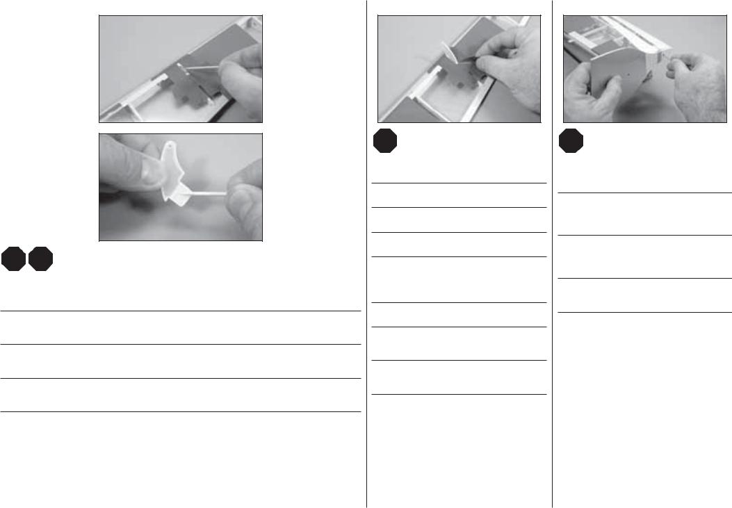
AILERON INSTALLATION•QUERRUDEREINBAU•INSTALLATION DES AILERONS•INSTALLAZIONE DEGLI ALETTONI
1 |
2 |
3 |
|||
|
|
|
|
|
|
|
|
|
|
|
|
LL |
|
|
|
LL |
RR |
|
The control horns for the ailerons have a longer lower |
|
RR |
|
|
tab than the control horns for the rudder and elevator. |
|
|
Separate the aileron from the wing. |
|
Make sure you are using the correct control horns for |
|
Use sandpaper to scuff the bottom of the aileron |
|
this section of the manual. |
|
||
|
|
|
control horns. |
|
Nehmen Sie das Querruder von den Tragfl ächen ab. |
|
|
|
|
|
Die Ruderhörner für die Querruder haben längere Zapfen |
|
|
|
|
|
Schleifen Sie mit Schleifpapier das Unterteil des |
||
|
|
|
||
Retirez l’aileron de l’aile. |
|
als die Ruderhörner der Seitenund Höhenruder. Bitte |
|
|
|
|
Queruderruderhornes an. |
||
|
|
stellen Sie sicher die richtigen Ruderhörner für diesen |
|
|
Staccare gli alettoni dall’ala |
|
|
|
|
|
Bauabschnitt bereit zu haben. |
|
Utilisez du papier abrasif pour dépolir la surface |
|
|
|
|
||
|
|
|
|
inférieure des guignols. |
|
|
Les guignols des ailerons ont une languette inférieure |
||
|
|
|
|
|
|
|
plus longue que celle des guignols de dérive et de |
|
Carteggiare la parte delle squadrette che andrà incollata |
|
|
profondeur. Assurez-vous d’utiliser les guignols |
|
agli alettoni. |
|
|
appropriés durant cette étape. |
|
|
|
|
|
|
|
|
|
|
|
|
|
|
Le squadrette di comando degli alettoni hanno una |
|
|
|
|
linguetta inferiore più lunga di quelle per timone ed |
|
|
|
|
elevatore. Bisogna quindi essere certi di usare le |
|
|
|
|
squadrette giuste. |
|
|
|
|
|
|
|
4
LL
RR
Place low-tack tape 1/32 inch (1 mm) from the control horn slot. This will prevent epoxy from getting on the aileron surface when the control horns are glued in place.
Kleben Sie Klebeband mit geringer Klebkraft in 1 mm Abstand um den Ruderhornschlitz. Dieses verhindert dass Epoxy beim Kleben auf die Ruderoberfl äche kommt.
Placez de l’adhésif de masquage à une distance de 1 mm autour de la fente destinée au guignol. Cela permet d’éviter de mettre de la colle sur la surface de l’aileron quand le guignol est collé en place.
Mettere del nastro a bassa adesività intorno alle fessure per le squadrette. Questo serve per evitare che la colla epoxy possa sporcare la superfi cie degli alettoni quando si incollano le squadrette.
EFL Slick 3D 480 |
11 |
5
LL |
15 |
|
RR |
||
|
Mix a small amount of 15-minute epoxy. Use a toothpick to apply epoxy in the slot for the control horn, and to the area of the control horn that fi ts into the aileron. Fit the control horn in the aileron. The horn will fi t snug in the slot. Use a paper towel and isopropyl alcohol to remove any excess epoxy from around the control horn.
Mischen Sie eine kleine Menge von 15 Minuten Epoxy und geben den Klebstoff mit einem Zahnstocher in den Schlitz und auf die Aufl agefl äche. Das Horn paßt saugend in den Schlitz. Wischen Sie überschüssigen Kleber mit einem Papiertuch und Reinigungsalkohol ab.
Mélangez une petite quantité de colle époxy 15 minutes. Utilisez un cure-dent pour appliquer la colle Epoxy dans la fente destinée à recevoir le guignol. Insérez le guignol dans l’aileron. Le guignol doit être correctement ajusté. Utilisez du papier absorbant et de l’alcool dénaturé pour retirer l’excès de colle autour du guignol.
Miscelare una piccola quantità di colla epoxy 15 minuti. Con uno stuzzicadenti applicarla nelle fessure per le squadrette e sulla parte delle squadrette che entra negli alettoni. Le squadrette si inseriscono precise negli alettoni. Togliere gli eccessi di colla intorno alle squadrette con un fazzoletto di carta e alcool isopropilico.
6
LL
RR
Before the epoxy fully cures, remove the tape from around the control horn.
Entfernen Sie das Klebeband bevor der Klebstoff vollständig getrocknet ist.
Retirez l’adhésif de masquage avant le séchage total de la colle époxy.
Prima che la colla sia asciutta, togliere il nastro messo prima intorno alle squadrette.
ÎUse caution when removing the tape as the clear covering is thin and can be easily torn.
ÎBitte sein Sie beim Entfernen der Folie sehr vorsichtig, da diese dünn ist und schnell reißen kann.
ÎDécollez l’adhésif de masquage avec précautions, l’entoilage transparent est très fin et peu facilement se déchirer.
ÎBisogna fare attenzione quando si toglie
il nastro perché il rivestimento trasparente è sottile e si potrebbe strappare facilmente.
7
LL
RR
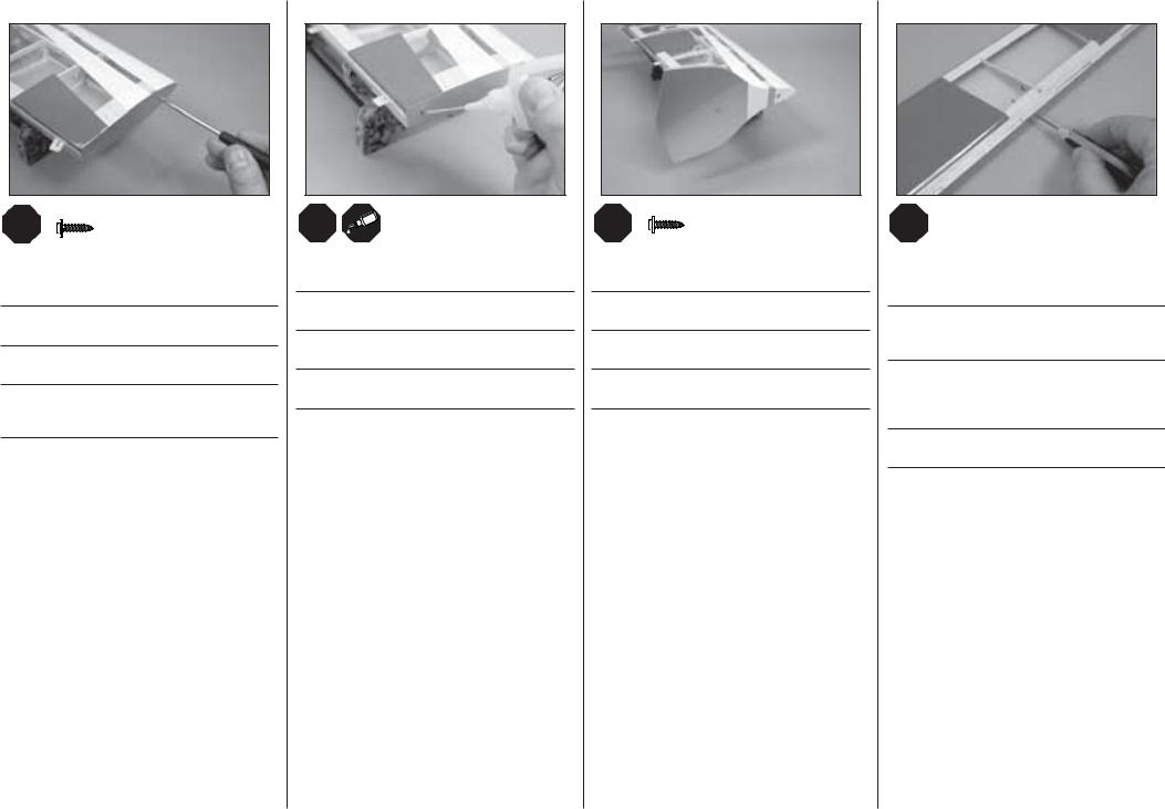
Place the Side Force Generator on the wing tip. Insert a t-pin in each of the mounting holes to locate the hard points in the wing tip for the mounting screws.
Setzen Sie den Side Force Generator auf die Flächenspitze. Stecken Sie eine T-Nadel in jede Seite der Montagelöcher um die Befestigungspunkte der Montageschrauben zu lokalisieren.
Placez le générateur de force latéral sur le saumon de l’aile. Insérez une épingle dans chaque trou afi n de
localiser emplacement des trous de vis de fi xation dans le saumon.
Sistemare sull’estremità alare i generatori di spinta laterale. Inserire uno spillo a T in ogni foro di montaggio per individuare il punto duro dell’ala in cui mettere le viti.
12 |
EFL Slick 3D 480 |
8
LL |
M2.5 x 10 |
RR |
|
|
x4 |
Use a #1 Phillips screwdriver to thread the screw into each of the holes in the wing tip. Remove the screw before proceeding.
Drehen Sie die Schraube mit einem Philips # 1 Schraubendreher in jedes Loch rein und wieder raus.
Utilisez un tournevis cruciforme #1 pour visser une vis dans chaque trou du saumon. Puis retirez la vis.
Usando un cacciavite con testa a croce avvitare una vite in ogni foro all’estremità alare. Togliere la vite prima di procedere.
9
LL
RR
Apply a few drops of CA in each of the holes to harden the threads created by the screw.
Geben Sie ein paar Tropfen dünnfl üssigen Sekundenkleber in die Löcher um die Gewinde zu härten.
Appliquez quelques gouttes de colle CA dans chaque trou afi n de durcir les fi lets taillés par la vis.
Mettere in ogni foro alcune gocce di colla CA per indurire la fi lettatura creata con la vite.
10
LL |
M2.5 x 10 |
RR |
x4 |
Attach the Side Force Generators to the wing tips using the hardware listed.
Schrauben Sie die Sideforce Generatoren mit den gelisteten Schrauben an die Tragfl äche.
Fixez les générateurs de force latérale aux saumons en utilisant les vis listées.
Fissare all’estremità alare il generatore di spinta laterale usando le viti indicate.
11
LL
RR
Use a pin vise and 1/16-inch (1.5mm) drill bit to drill a hole in the center of each hinge slot. Prepare both the aileron and wing at this time.
Bohren Sie mit einem 1,5mm Handbohrer ein Loch in die Mitte jeden Scharnierschlitzes. Bereiten Sie so beide Querruder und Tragfl ächen vor.
Utilisez un porte-foret muni d’un foret de 1.5mm pour percer un trou au centre de chaque rainure de charnière. Préparez les deux ailes et les deux ailerons lors de cette étape.
Con una punta da 1,5mm forare al centro di ogni fessura per le cerniere, sia sugli alettoni che sull’ala.
EFL Slick 3D 480 |
13 |

12
LL
RR
Place a T-pin in the center of each hinge. Slide the hinges into the slots in the wing. The t-pin will rest against the edge of the wing as shown.
Stecken Sie eine T-Nadel in die Mitte jeden Scharnieres. Die Nadel bleibt beim Einstecken dann an der
Tragfl ächenkante.
Placez une épingle en T au centre de chaque charnière. Glissez les charnières dans les fentes de l’aile. L’épingle doit être en appui contre le bord de fuite de l’aile comme sur l’illustration.
Mettere uno spillo a T al centro di ciascuna cerniera, poi inserirla nella sua fessura sull’ala. Lo spillo deve andare fi n contro il bordo dell’ala, come si vede dalla fi gura.
13
LL
RR
Fit the aileron into position. Position the aileron so the gap at the root of the aileron between the wing, and the gap between the tip of the aileron and the Side Force Generator are equal. Remove the t-pins from the hinges at this time.
Setzen Sie das Querruder in Position. Richten Sie das Ruder so aus, dass der Spalt an der Tragfl ächeninnenseite und an den Side Force
Generatoren gleich ist. Nehmen Sie jetzt die T-Nadeln aus den Scharnieren.
Placez l’aileron en position. Placez l’aileron de façon à obtenir le même écart entre l’aileron et l’emplanture de l’aile et entre l’aileron et le générateur de force latérale. Retirez les épingles des charnières.
Inserire l’alettone nella sua sede e posizionarlo in modo che le fessure alla radice e all’estremità dell’ala siano uguali. A questo punto togliere gli spilli dalle cerniere.
14
LL
RR
Set the hinge gap by placing a #11 blade between the aileron and wing. This will set the correct gap between them and allow for full throw of the ailerons.
Justieren Sie den Scharnierspalt mit der Klinge eines 11 Hobbymessers zwischen Ruder und Tragfl äche. Dieses sorgt für den richtigen Abstand und ermöglicht volle Ausschläge.
Ajustez la position de l’aileron par rapport à l’aile en plaçant une lame #11 entre les deux. L’épaisseur de la lame correspond à l’écart nécessaire entre
la gouverne d’aileron et l’aile pour obtenir les débattements maximum.
Per avere la giusta distanza tra alettone ed ala nel punto di cerniera, si può inserire un cacciavite #11. Si avrà così tutta la corsa necessaria per l’alettone.
15
LL
RR
Apply thin CA to the top and bottom of each hinge. Once the CA cures, gently pull on the fi xed surface and control surface to make sure the hinges are glued securely. If not, apply additional CA to secure each of the hinges. Remove the Side Force Generators and set them aside.
Tragen Sie oben und unten an jedem Scharnier eine dünne Linie Sekundenkleber auf. Wenn der Klebstoff ausgehärtet ist, ziehen Sie vorsichtig am Ruder und Ruderblatt um sicherzustellen, dass die Scharniere fest angeklebt sind. Ist dies nicht der Fall, tragen Sie noch etwas Sekundenkleber auf, um die Scharniere zu
befestigen. Entfernen Sie die Side Force Generatoren und legen diese zur Seite.
Appliquez de colle CA fl uide sur le dessus et le dessous de chaque charnière. Une fois le séchage de la colle terminé, tirez doucement sur la gouverne pour contrôler le collage des charnières. Si le collage n’est pas
suffi sant, appliquez de nouveau de la colle CA sur chaque charnière. Retirez les générateur de force latérale et rangez-les soigneusement.
Mettere della colla CA liquida sopra e sotto ad ogni cerniera. Quando la colla è asciutta, tirare delicatamente le superfi ci mobili per accertarsi che l’incollaggio sia sicuro. In caso contrario aggiungere altra colla sulle cerniere. Togliere il generatore di spinta laterale e metterlo da parte.
14 |
EFL Slick 3D 480 |
AILERON SERVO INSTALLATION•EINBAU DER QUERRUDERSERVOS•INSTALLATION DES SERVOS D’AILERONS•INSTALLAZIONE SERVO ALETTONI
1 |
2 |
3 |
|||||
|
|
|
|
|
|
|
|
|
|
|
|
|
|
|
|
LL |
|
LL |
|
LL |
RR |
|
RR |
|
RR |
Secure the aileron servo in the wing with the servo output facing toward the aileron. The servo lead can be retrieved |
|
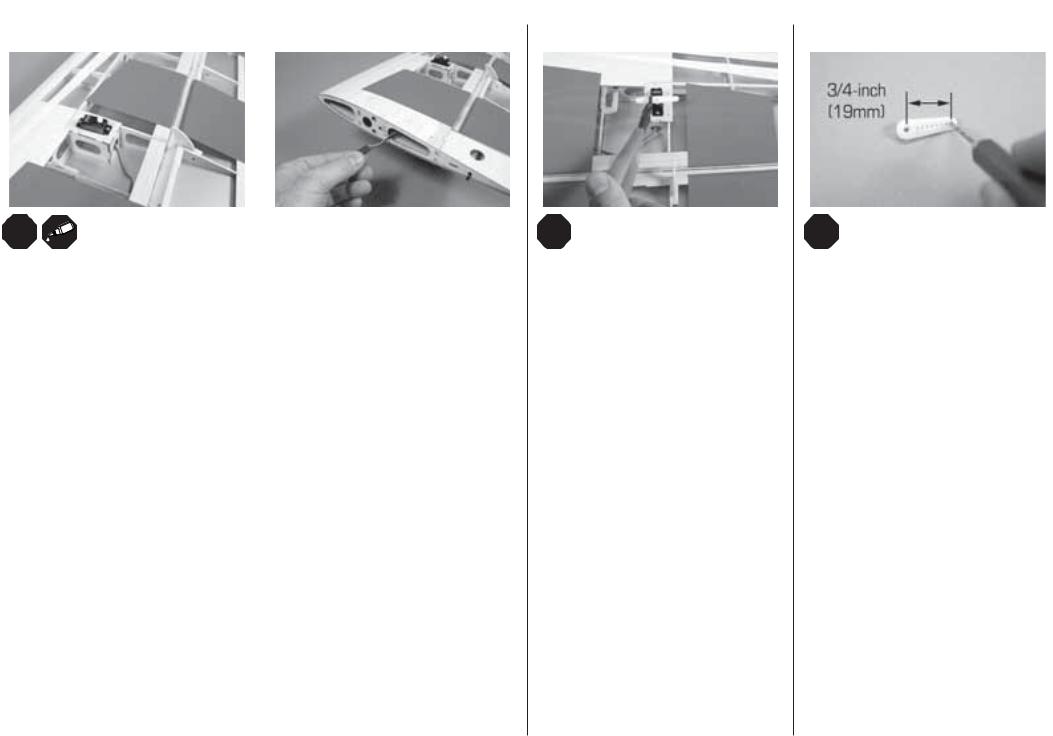
Use the radio system to center the aileron servo. Fit |
Use a pin vise and 5/64-inch (2mm) drill bit to enlarge |
|
through the wing root as shown. Thread the servo mounting screws into the pre-drilled holes in the wing. Remove the |
|
the servo arm on the servo so it is parallel to the hinge |
the hole in the servo arm for the screw that retains the |
|
screws, then lift the servo and apply a few drops of thin CA in the holes to harden the threads made by the screws. |
|
line. Use side cutters to remove the arm opposite the |
ball link. |
|
Reinstall the screws. |
|
control horn. |
|
|
|
Vergrößern Sie mit einem 2mm Handbohrer das Loch in |
|||
|
|
|
||
Schrauben Sie das Queruderservo mit dem Abtrieb in Richtung Querruder in die Tragfl äche. Das Servokabel wird |
|
|
||
|
Zentrieren Sie mit der Fernsteuerung das |
dem Servoarm zur Aufnahme des Kugelkopfanschlusses. |
||
dabei wie abgebildet durch die Tragfl ächenwurzel nach außen geführt. |
|
Querruderservo. Setzen Sie den Servoarm so auf, |
|
|
|
Utilisez un porte foret muni d’un foret de 2mm pour |
|||
|
|
dass er parallel zur Scharnierlinie ist. Schneiden Sie |
||
|
|
|||
Installez le servo d’aileron sur l’aile, la tête du servo orientée vers l’aileron. Guidez le câble dans l’aile pour le faire |
|
agrandir le trou du bras se situant à 19mm du centre. |
||
|
die nicht benötigte Seite des Servoarms mit einem |
|||
sortir par l’emplanture de l’aile comme sur l’illustration. Vissez une vis de fi xation de servo dans les trous pré-percés |
|
|
|
|
|
Seitenschneider ab. |
Con una punta da 2mm allargare il foro sulla squadretta |
||
de l’aile. Retirez la vis, soulevez le servo et appliquez quelques gouttes de colle CA dans les trous pour durcir les |
|
|||
|
|
|||
|
|
del servo per la vite di ritenuta dell’attacco a sfera. |
||
fi lets. Fixez le servo à l’aide des 2 vis. |
|
Utilisez votre radio pour placer le servo d’aileron au |
||
|
|
|
||
|
|
neutre. Placez le bras de servo à la parallèle de l’axe de |
|
|
Fissare nell’ala il servo per l’alettone in modo che il suo albero di uscita sia rivolto verso l’alettone stesso. Bisogna poi |
|
|
||
|
charnière. Utilisez une pince coupante pour retirer la |
|
|
|
far passare il cavetto del servo attraverso la radice dell’ala come si vede in fi gura. Avvitare le viti del supporto servo |
|
|
|
|
|
partie inutilisée du bras. |
|
|
|
nei fori già preparati sull’ala. Togliere le viti e sollevare il servo per mettere alcune gocce di colla CA nei fori e indurire |
|
|
|
|
|
|
|
|
|
|
|
|
|
|
il fi letto fatto dalle viti. A colla asciutta, rimettere le viti. |
|
Con il radiocomando centrare il servo alettoni. |
|
|
|
|
Mettere la squadretta sul servo in modo che sia |
|
|
|
|
|
||
|
|
parallela alla linea di cerniera. Eliminare i bracci non |
|
|
|
|
utilizzati della squadretta. |
|
|
|
|
|
|
|
EFL Slick 3D 480 |
15 |
 Loading...