


P-47Thunderbolt
Assembly Manual

Table of Contents
Table of Contents........................................................ |
2 |
Specifications............................................................. |
2 |
Contents of Kit/Parts Layout......................................... |
3 |
Required Radio Equipment........................................... |
4 |
Required Power System Equipment ............................... |
4 |
Required Tools and Adhesives...................................... |
5 |
Optional High Power Inrunner Brushless Motor Power |
|
System Required Equipment* ....................................... |
6 |
Optional Sport Outrunner Brushless Motor Power System |
|
Required Equipment* .................................................. |
6 |
Optional High Power Outrunner Brushless Motor Power |
|
System Required Equipment ......................................... |
7 |
Optional Accessories .................................................. |
7 |
Using the Manual ....................................................... |
8 |
Warning.................................................................... |
8 |
Before Starting Assembly............................................. |
8 |
Note on Lithium Polymer Batteries................................. |
8 |
Warranty Information.................................................. |
9 |
|
Wing Preparation |
..................................................... |
10 |
Wing Installation ...................................................... |
|
14 |
Stabilizer Installation................................................. |
15 |
|
Optional Rudder....................................................... |
|
19 |
Radio Installation...................................................... |
|
22 |
Stock Motor Installation ............................................. |
27 |
|
Inrunner Motor InstallationPark ............................400 |
30 |
|
Outrunner Motor Installation....................................... |
35 |
|
Final Assembly ......................................................... |
|
39 |
Control Throws......................................................... |
|
41 |
Range Testing the ............................................Radio |
42 |
|
Preflight................................................................... |
|
42 |
Notes...................................................................... |
|
44 |
2005 Official AMA |
|
|
National Model Aircraft ..........................Safety Code |
46 |
|
|
Specifications |
|
Wingspan: |
39" (990mm) |
|
Length: |
32" (813mm) |
|
Wing Area: |
260 sq in (16.8 sq dm) |
|
Weight w/o Battery: 18–21 oz (510–595 g) |
|
|
Weight w/ Battery: 21–26 oz (595–737 g) |
|
|
2
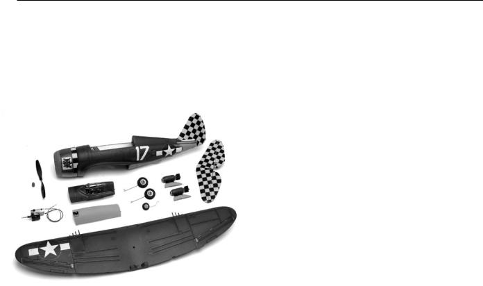
Contents of Kit/Parts Layout
Large Replacement Parts: |
Small Replacement Parts |
||
EFL6001 |
Wing |
EFL6006 |
Hardware and Pushrod Set |
EFL6002 |
Fuselage |
EFL6007 |
Landing Gear Set |
EFL6003 |
Hatch |
EFL6008 |
Bomb and Pylon Set |
EFL6004 |
Cowl |
EFL6009 |
Decal Set |
EFL6005 |
Horizontal Tail |
EFLM232 |
480 Motor w/19T 0.5 Module Pinion |
|
|
EFLM236 |
400 Gearbox, w/56T 0.5M Spur Gear |
|
|
EFLM237 |
Spur Gear, 56T 0.5 Module with Shaft |
|
|
EFLM238 |
Spur Gear, 56T 0.5 Module |
|
|
EFLM1915 |
Outrunner Stick Mount |
|
|
EFLP1080E |
10x8 Electric Prop |
|
|
|
|
3

Required Radio Equipment
You will need a 3-channel or greater radio transmitter and micro receiver (at least 4-channel with optional rudder). You can choose from the equipment below including a complete radio system or separate receiver, crystal and servos when using your existing radio equipment.
JSP14010** |
JR Sport 4-Channel System MD2 UL |
|
—Complete radio system (Includes 2 |
|
servos) |
or |
|
JSP30610 |
6CH UL FM Receiver w/o crystal, |
|
Positive Shift (JR/AIRZ) |
or |
|
JSP30615 |
6CH UL FM Receiver w/o crystal, |
|
Negative Shift (HRC/FUT) |
JRPXFR** |
FM Receiver Crystal |
EFLRS75 |
7.5-Gram Sub-Micro Servo (3 or 4 w/ |
|
optional rudder) |
JSP98020 |
Y-Harness, Standard 6" |
Required Power System Equipment
For stock brushed power system only. Please see optional brushless power system required equipment when choosing brushless power system alternatives.
CSEP20P |
Pixie-20P Sub Micro ESC |
EFLA239 |
Female Bullet Plug w/Lead |
THP21003SPL |
2100mAh 3-Cell 11.1V Li-Po, 16GA |
EFLC3005 |
Celectra 1-3 Cell Li-Po Charger |
WSD1300 |
Ultra Plug, Male/Female Set (2) |
Substituting the 3-Cell Li-Po pack and charger with a 9-Cell Ni-MH pack and charger offers slightly reduced performance and duration but provides a good power pack alternative:
PKZ1027 10.8V 1000mAh Ni-MH Battery PKZ1519 5–10 Cell DC Peak Charger
4

RequiredTools and Adhesives
Tools & Equipment |
|
EFLA257 |
Screwdriver, #0 Phillips (Or included |
|
with EFLA250) |
EFLA258 |
Screwdriver, #1 Phillips (Or included |
|
with EFLA250) |
EFLA250 |
Park Flyer Tool Assortment, 5pc |
Hobby knife
Drill
Drill bit: .050", 5/32"
Straight edge
Felt tipped pen
Razor saw
Sandpaper
Adhesives |
|
EFLA206 |
Foam Compatible Thick CA |
|
(Or included with EFLA208) |
EFLA207 |
Foam Compatible Activator |
|
(Or included with EFLA208) |
EFLA208 |
Foam CA/Activator Pack |
EFLA209 |
Foam Compatible Medium CA |
Low-temperature hot glue
5

Optional High Power Inrunner
Brushless Motor Power System
Required Equipment*
This is the most powerful optional power system well suited for large field flying and “full house” airframe configurations (i.e. – landing gear, rudder, etc. installed). Use with the included gearbox and optional 6.5:1 gear ratio.
EFLM1100 |
Park 400 Inrunner Brushless, 4200Kv |
EFLM1912 |
Heat Sink, 20mm x 20mm |
|
Park 400 Inrunner |
EFLA311B |
20-Amp Brushless ESC (V2) |
EFLM243 |
Spur Gear, 65T 0.5 Module |
EFLM1951 |
Pinion Gear, 10T 0.5 Module 2mm I.D. |
EFLP1170 |
11x7 Slow Flyer Propeller (2) |
THP21003SPL |
2100mAh 3-Cell 11.1V Li-Po, 16GA |
EFLC3005 |
Celectra 1-3 Cell Li-Po Charger |
WSD1300 |
Ultra Plug, Male/Female Set (2) |
*Proper throttle management is required when using high performance setups.
Optional Sport Outrunner Brushless
Motor Power System Required
Equipment*
This powerful optional power system is well suited for small field flying and “lightweight” airframe configurations (i.e. – no landing gear, no rudder, etc installed). Use with the included 10x8E prop and outrunner stick mount.
EFLM1305 |
Park 400 Outrunner Brushless, 920Kv |
EFLA311B |
20-Amp Brushless ESC (V2) |
THP21003SPL |
2100mAh 3-Cell 11.1V Li-Po, 16GA |
EFLC3005 |
Celectra 1-3 Cell Li-Po Charger |
WSD1300 |
Ultra Plug, Male/Female Set (2) |
*Proper throttle management is required when using high performance setups.
6

Optional High Power Outrunner
Brushless Motor Power System
Required Equipment
This powerful optional power system is well suited for large field flying and “full house” airframe configurations (i.e. - landing gear, rudder, etc. installed). Use with the included 10x8E prop and outrunner stick mount.
EFLM1400 |
Park 450 Outrunner Brushless, 890Kv |
EFLA311B |
20-Amp Brushless ESC (V2) |
THP21003SPL |
2100mAh 3-Cell 11.1V Li-Po, 16GA |
EFLC3005 |
Celectra 1-3 Cell Li-Po Charger |
WSD1300 |
Ultra Plug, Male/Female Set (2) |
Substituting the 3-Cell Li-Po pack and charger with a 9-Cell Ni-MH pack and charger offers slightly reduced performance and duration but provides a good power pack alternative:
PKZ1027 10.8V 1000mAh Ni-MH Battery PKZ1519 5–10 Cell DC Peak Charger
*Proper throttle management is required when using high performance setups.
|
|
Optional Accessories |
|
|
|
EFLA110 |
Power Meter |
|
EFLA212 |
Gear Puller: 1mm–5mm Shaft |
|
7

Using the Manual
This manual is divided into sections to help make assembly easier to understand, and to provide breaks between each major section.
Remember to take your time and follow the directions.
Warning
An RC aircraft is not a toy! If misused, it can cause serious bodily harm and damage to property. Fly only in open areas, preferably at AMA (Academy of Model Aeronautics) approved flying sites, following all instructions included with your radio.
Keep loose items that can get entangled in the propeller away from the prop, included loose clothing, or other objects such as pencils and screwdrivers. Especially keep your hands away from the propeller.
Before Starting Assembly
Before beginning the assembly of your P-47D Thunderbolt, remove each part from its bag for inspection. Closely inspect the fuselage, hatch, wing and stabilizer for damage. If you find any damaged or missing parts, contact the place of purchase.
Note on Lithium Polymer Batteries
Lithium Polymer batteries are significantly more volatile than alkaline or Ni-Cd/ Ni-MH batteries used in RC applications. All manufacturer’s instructions and warnings
must be followed closely. Mishandling of Li-Po batteries can result in fire. Always follow the manufacturer's instructions when disposing of Lithium Polymer batteries.
8

Warranty Information
Horizon Hobby, Inc. guarantees this kit to be free from defects in both material and workmanship at the date of purchase. This warranty does not cover any component parts damage by use or modification. In no case shall Horizon Hobby’s liability exceed the original cost of the purchased kit. Further, Horizon Hobby reserves the right to change or modify this warranty without notice.
In that Horizon Hobby has no control over the final assembly or material used for the final assembly, no liability shall be assumed nor accepted for any damage resulting from the use of the final assembled product. By the act of using the assembled product, the user accepts all resulting liability.
Please note that once assembly of the model has been started, you must contact Horizon Hobby, Inc. directly regarding any warranty question. Please do not contact your local hobby shop regarding warranty issues, even if that is where you purchased it. This will enable Horizon to better answer your questions and service you in the event that you may need any assistance.
If the buyer is not prepared to accept the liability associated with the use of this product, the buyer is advised to return this kit immediately in new and unused condition to the place of purchase.
Horizon Hobby, Inc.
4105 Fieldstone Road
Champaign, Illinois 61822
877-504-0233
horizonhobby.com
9

|
|
Wing Preparation |
|
|
|
Required Parts |
|
|
• Wing |
• Servo (2) |
|
• Y-Harness |
• Aileron pushrod (2) |
|
•Landing gear screws (4)
•18mm x 20mm two-sided tape (2)
Required Tools and Adhesives
• Drill |
• Drill bit: .050" |
•Hobby knife
•Low-temperature hot glue
•Phillips screwdriver (small)
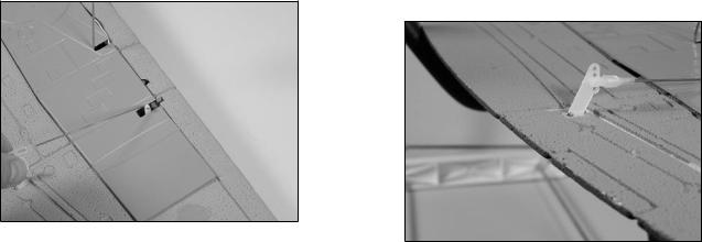
1. Use the radio system to electronically center the aileron servos. Attach a control horn to each of the servos.
2. Apply the 18mm x 20mm two-sided tape to the servos. Test fit the servos into the wing. The
servo arm faces to the leading edge. After fitting, remove the backing from the tape to secure the servos into the wing.
10
3. Attach the Y-Harness to both servos. Route the single lead of the Y-Harness through the hole in the center of the wing.
Hint: Use tape to secure the servo leads to the Y-Harness so they won’t accidentally unplug.
Note: If using a radio with the appropriate mixing capability, two 12" servo extensions can be used instead of the Y-Harness for the aileron servos.
Note: The landing gear is optional and can be left off when flying from rough surfaces or tall grass that could damage the gear. Skip to Step 6 if the landing gear will not be installed.
4. Attach the main landing gear using four landing gear mounting screws (2mm x 6mm).
11

5. Attach the tail wheel using two landing gear mounting screws (2mm x 6mm).
6. Test fit the wing covers. Trim around the landing gear and servo arm as necessary. Remove the backing from the two-sided tape on the covers. Carefully place the wing covers into position, pressing them against the wing to secure them.
Hint: Use clear tape to keep the servo lead and extension in the channel in the wing.
12
7. Attach the “Z” bend of the pushrod to the aileron servo arm. Use a hobby knife or .050" drill bit to ream out the servo arm if necessary to fit the pushrod.
8. Turn the radio system on and plug the Y-Harness lead into the receiver. Snap the clevis onto the control horn. Thread the clevis either in or out so the aileron is centered when the servo is centered.
13
Wing Installation
Required Parts
• Wing • Fuselage
• Belly pan
Required Tools and Adhesives
•Phillips screwdriver
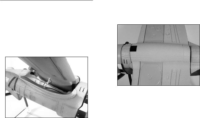
1. Place the wing onto the fuselage. Make sure to pass the Y-Harness lead through the opening in the fuselage.
2. Place the belly pan onto the wing and fuselage. The mounting plate at the rear of the belly pan keys into the fuselage mounting plate. Use the screw at the front to secure the belly pan and wing to the fuselage.
14
Stabilizer Installation
Required Parts
•Fuselage assembly
•Stabilizer w/elevators and hinges
Required tools and Adhesives
• Sandpaper |
• Hobby knife |
•Foam-safe CA
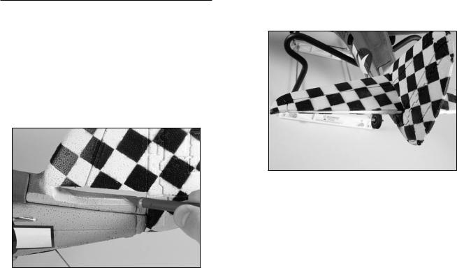
1. Carefully remove any flashing from the opening in the fuselage for the stabilizer.
2. Remove the elevators and joiner wire with bushings from the stabilizer. Slide the stabilizer into the fuselage.
Note: You may need to sand the fuselage opening slightly for proper fit of the stabilizer.
15
 Loading...