


 Loading...
P-40 Warhawk 300 ARF
Assembly Manual
|
|
Specifications |
|
|
Wingspan: |
25.6 in (650mm) |
|
|
|
|
|
|||
Wing Area: |
108 sq in (7.02 sq dm) |
|
|
|
Length: |
21.7 in (550mm) |
|
|
|
Weight (without battery): |
5.5–6.0 oz (156–170 g) |
|
|
|
Weight (with Li-Po Battery): |
6.5–7.0 oz (184–198 g) |
|
|
|
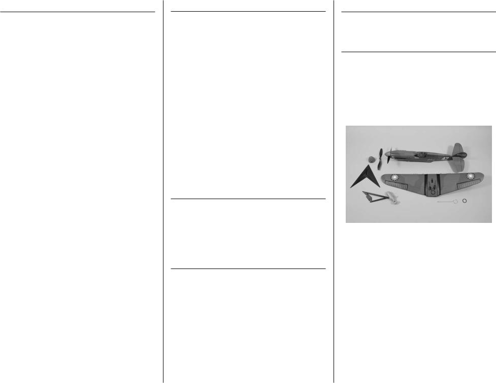
Table of Contents |
|
Introduction............................................................ |
2 |
Important Warranty Information.............................. |
2 |
Using the Manual................................................... |
2 |
Product Registration................................................ |
2 |
Contents of Kit/Parts Layout.................................... |
2 |
Recommended Radio Equipment.............................. |
3 |
Additional Electronics.............................................. |
3 |
Optional Accessories.............................................. |
3 |
Required Tools and Adhesives.................................. |
3 |
Note on Lithium Polymer Batteries............................ |
3 |
Electronics Installation............................................. |
3 |
Linkage Connections............................................... |
6 |
Wing Installation.................................................... |
8 |
Battery Installation.................................................. |
9 |
Spinner Installation................................................. |
9 |
Propeller Removal and Replacement....................... |
10 |
Display Stand Assembly........................................ |
11 |
Control Throws..................................................... |
12 |
Center of Gravity.................................................. |
13 |
Preflight............................................................... |
13 |
Range Test Your Radio........................................... |
14 |
Flying Your P-40 Warhawk.................................... |
14 |
Safety Do’s and Don’ts for Pilots............................. |
14 |
Age Requirements................................................. |
14 |
Safety, Precautions and Warnings.......................... |
15 |
Warranty Information........................................... |
15 |
CE Compliance Information for the |
|
European Union.............................................. |
17 |
2009 Official Academy of |
|
Model Aeronautics Safety Code........................ |
17 |
Declaration of Conformity..................................... |
18 |
2
Introduction
Thank you for purchasing the E-flite® P-40 Warhawk 300 ARF. On paper, the P-40 was outclassed by many of the foes it faced. But in the hands of the pilots of the American Volunteers Group, the Warhawk was used to deadly effect against “superior” Zeros. Their exploits made the iconic shark-toothed grin of the “Flying Tigers” a symbol of victory for the Allies and cause for concern to any enemy pilot that encountered it.
E-flite has captured the spirit of the Tigers in this fun- to-fly recreation of the P-40 that goes together fast and is small enough to fly in the park. It comes out of the box loaded with scale details like an authentic Flying Tigers paint scheme and molded panel lines. It also comes equipped with a factory-installed 300 BL outrunner motor that will provide plenty of power for
warbird aerobatics like loops, rolls and Immelmans. Its simple 3-channel control setup means you only need to buy two servos – one for aileron and one for elevator
– making it even more affordable to get flying. When you’re not flying, you can show off its scale looks with included static display stand.
Important Warranty Information
Please read our Warranty and Liability Limitations section on Page 14 before building this product. If you as the Purchaser or user are not prepared to accept the liability associated with the use of this Product, you are advised to return this Product immediately in new and unused condition to the place of purchase.
Using the Manual
This manual is divided into sections to help make assembly easier to understand, and to provide breaks between each major section. In addition, check boxes have been placed next to each step to keep track of its completion.
Remember to take your time and follow the directions.
Product Registration
Register your product online at: www.e-fliterc.com/register/
Contents of Kit/Parts Layout
EFL6076 |
Fuselage with Tail and Hatch |
|
EFL6077 |
Main Wing |
|
EFL6078 |
Propeller (2) |
|
EFL6079 |
Spinner |
|
EFL6080 |
Motor |
|
EFL6081 |
Canopy Hatch |
|
EFL6082 |
Wing Mount O-rings (3) |
|
EFL6083 |
Horizontal Stabilizer |
|
|
|
|
|
|
|
E-flite P-40 Warhawk Assembly Manual
Recommended Radio Equipment
You will need a minimum 4-channel transmitter, receiver, and two servos. You can also choose to purchase a complete radio system. If you are using an existing transmitter, just purchase the other required equipment separately. We recommend the crystalfree, interference-free Spektrum™ DX5e 2.4GHz DSM® 5-channel system.
If you own the Spektrum DX5e radio, just add the AR6100e DSM2™ 6-channel receiver and two E-flite S60 Super Sub-Micro Servos.
Transmitter and Receiver
SPMAR5500 |
DX5e 5-Channel Transmitter only, |
|
Mode 2 |
Purchase Separately |
|
SPMAR6100E |
AR6100E 6-Channel Receiver, Air |
And |
|
EFLRS60 |
S60 Super Sub Micro Servo (2) |
Additional Electronics
EFLB4302SJ |
430mAh 2S 7.4V 20C LiPo, |
|
20AWG JST |
EFLA1010 |
10-Amp Pro Brushless ESC |
The Spektrum trademark is used with permission of Bachmann Industries, Inc.
E-flite P-40 Warhawk Assembly Manual
Optional Accessories
EFLA110 |
Power Meter |
EFLC3005 |
Celectra™ 1–3 Cell |
|
Li-Po Charger |
EFLC505 |
Intelligent 1- to 5-Cell |
|
Balancing Charger |
Required Tools and Adhesives
Tools & Equipment
Hobby knife with #11 blade Phillips screwdriver: #0
Flat blade screwdriver Nut driver: 5mm Two-sided tape
Ruler
Adhesives
Foam CA 1oz/Activator 2 oz Pack (EFLA208) Canopy Glue (PAAPT56)
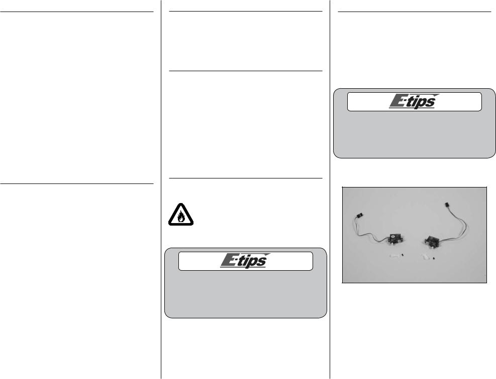
Note on Lithium Polymer Batteries
Lithium Polymer batteries are significantly more volatile than alkaline or Ni-Cd/ Ni-MH batteries used in RC applications. All manufacturer’s instructions and warnings must be followed closely. Mishandling of Li-Po batteries can result in fire. Always follow the manufacturer’s instructions when disposing of Lithium Polymer batteries.
During the course of building your model we suggest that you use a soft base for the building surface.
Such things as a foam stand, large piece of bedding foam or a thick bath towel will work well and help protect the model from damage during assembly.
Electronics Installation
Required Parts |
|
Fuselage assembly |
Wing assembly |
Servo with horn (2) |
Receiver |
Speed control |
Flight battery |
Transmitter |
|
Required Tools |
|
Foam-safe CA |
Hobby knife with #11 blade |
Two-sided tape |
Phillips screwdriver: #0 |
If you are using a computer radio, it is recommended to start with a new program and clear it before starting the installation of the electronics. Make sure the trims, sub-trims and sticks are centered, and no programmable mixing has been turned on as well.
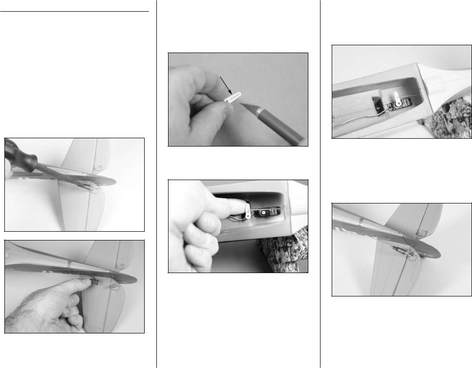
1. Use a #0 Phillips screwdriver to remove the servo horns from the two servos.
3
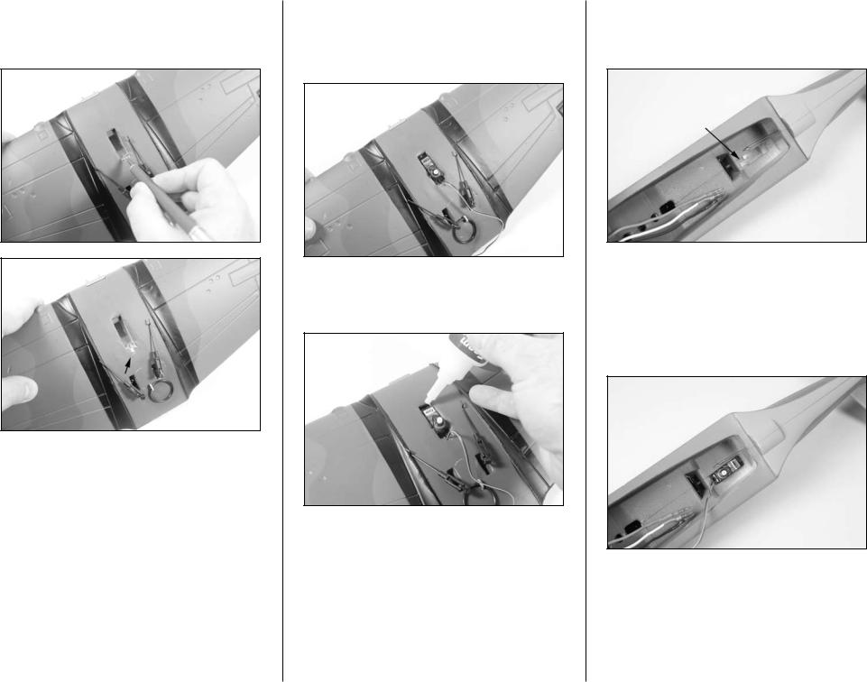
2. Use a hobby knife with a #11 blade to cut a narrow notch at the edge of the servo pocket in the wing to allow the servo wire from the aileron servo to fit in.
4
3. Press the servo into the servo pocket in the wing. Make sure to guide the servo wire into the notch made in the previous step. Note that the output of the servo faces to the trailing edge (rear) of the wing.
4. Place a drop or two of foam-safe CA in the hole in the servo tab. The CA will go through the hole and bond the servo to the wing.
5. Use a hobby knife with a #11 blade to cut a narrow notch at the edge of the servo pocket in the fuselage for the elevator servo to allow the servo wire to fit in.
6. Press the servo into the servo pocket in the fuselage. Make sure to guide the servo wire into the notch made in the previous step. Note that the output of the servo faces to the front of the fuselage. Place a drop or two of foam-safe CA in the hole in the servo tab. The CA will go through the hole and bond the servo to the fuselage.
E-flite P-40 Warhawk Assembly Manual
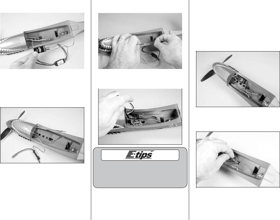
7. Plug the speed control and elevator servo |
9. Connect the leads from the motor to the |
11. Check the operation of your motor at this |
||
|
connectors into the receiver. |
|
speed control. |
time using the radio system. The motor should |
|
|
|
|
spin counterclockwise when viewed from the front |
|
|
|
|
of the fuselage. If not, follow the speed control |
|
|
|
|
manufacturer’s recommendations to reverse the |
|
|
|
|
direction if necessary. Once the direction of |
|
|
|
|
rotation is verified, you can install the propeller |
|
|
|
|
back on the motor. |
|
|
|
|
12. Tuck the motor leads in the fuselage as shown. |
|
|
|
|
|
|
8. Place a small piece of two-sided tape on the |
|
10. Use two-sided tape to secure the speed control |
|
|
receiver. Slide the receiver into the fuselage and |
|
in the fuselage as shown. |
|
|
press it against the tape to secure it into the |
|
|
|
|
fuselage. Make sure to leave enough of the receiver |
|
|
|
|
exposed to know which port to plug the aileron |
|
|
|
|
servo into. |
|
|
|
13. Insert the lead for the battery from the speed control into the larger hole in the fuselage. The lead will enter the compartment under the canopy.
Before checking the rotation of your motor, make sure to remove the propeller to avoid any accidental injuries. The details for removing the propeller can be found on Page 10, “Propeller Removal and Installation.”
E-flite P-40 Warhawk Assembly Manual |
5 |
Linkage Connections
Required Parts |
|
Fuselage assembly |
Wing assembly |
Flight battery |
Transmitter |
Single-sided servo horn |
|
Double-sided servo horn |
|
Required Tools |
|
Ruler |
Flat blade screwdriver |
Phillips screwdriver: #0
Hobby knife with #11 blade
1. Inspect the clevis and its connection to the elevator control horn. Note which hole the clevis is attached to. Use a flat blade screwdriver to open the clevis and remove it from the elevator control horn.
6
2. Use a hobby knife to enlarge the hole in a single-sided servo horn that is 9/32-inch (7mm) from the center of the servo horn. The hole needs to be big enough to insert the pushrod wire for the elevator. Use care not to make the hole too large as this will cause slop in the control system.
3. Insert the pushrod wire from the elevator into the hole enlarged in the previous step.
4. Use the radio system to center the elevator servo. Secure the servo horn to the elevator servo using the screw removed in the previous section of the manual. You will need a #0 Phillips screwdriver to tighten the screw.
5. Reconnect the clevis to the elevator control horn in the hole noted in Step 1. Make sure the clevis is secure before proceeding. Check to see that the elevator is level when the servo is centered. If not adjust the clevis to the correct length by adjusting the clevis in or out on the pushrod.
E-flite P-40 Warhawk Assembly Manual
Loading...