


IMPORTANT: |
IMPORTANT : |
IMPORTANTE: |
Read Before Using |
Lire avant usage |
Leer antes de usar |
|
|
|
Operating/Safety Instructions

 Consignes de fonctionnement/sécurité Instrucciones de funcionamiento y seguridad
8220
P.O. Box 081126 Racine, WI 53408-1126
|
|
Call Toll Free for |
Pour obtenir des informations |
Llame gratis para |
|
|
|
Consumer Information |
et les adresses de nos centres |
obtener información |
|
||
|
|
& Service Locations |
de service après-vente, |
para el consumidor y |
|
|
|
|
|
appelez ce numéro gratuit |
ubicaciones de servicio |
|
|
|
|
|
|
|
||
|
|
1-800-4-DREMEL (1-800-437-3635) www.dremel.com |
|
|
||
|
|
|
|
|
|
|
|
For English Version |
Version française |
Versión en español |
|
||
|
|
See page 2 |
Voir page 31 |
Ver la página 61 |
|
|
|
|
|
|
|
|
|
Safety Symbols
The definitions below describe the level of severity for each signal word. Please read the manual and pay attention to these symbols.
This is the safety alert symbol. It is used to alert you to potential
! personal injury hazards. Obey all safety messages that follow this symbol to avoid possible injury or death.
DANGER indicates a hazardous situation which, if not avoided, will result in death or serious injury.
Work area safety
Keep work area clean and well lit. Cluttered or dark areas invite accidents.
Do not operate power tools in explosive atmospheres, such as in the presence of flammable liquids, gases or dust. Power tools create sparks which may ignite the dust or fumes.
Keep children and bystanders away while operating a power tool. Distractions can cause you to lose control.
Electrical safety
Power tool plugs must match the outlet. Never modify the plug in any way. Do not use any adapter plugs with earthed (grounded) power tools. Unmodified plugs and matching outlets will reduce risk of electric shock.
Avoid body contact with earthed or grounded surfaces such as pipes, radiators, ranges and refrigerators. There is an increased risk
of electric shock if your body is earthed or grounded.
Do not expose power tools to rain or wet conditions. Water entering a power tool will increase the risk of electric shock.
Do not abuse the cord. Never use the cord for carrying, pulling or unplugging the power tool. Keep cord away from heat, oil, sharp edges or moving parts. Damaged or entangled cords increase the risk of electric shock.
When operating a power tool outdoors, use an extension cord suitable for outdoor use. Use of a cord suitable for outdoor use reduces the risk of electric shock.
If operating the power tool in damp locations is unavoidable, use a Ground Fault Circuit Interrupter (GFCI) protected supply. Use of an GFCI reduces the risk of electric shock.
Personal safety
Stay alert, watch what you are doing and use common sense when operating a
2

power tool. Do not use a power tool while you are tired or under the influence of drugs, alcohol or medication. A moment of inattention while operating power tools may result in serious personal injury.
Use personal protective equipment. Always wear eye protection. Protective equipment such as dust mask, non-skid safety shoes, hard hat, or hearing protection used for appropriate conditions will reduce personal injuries.
Prevent unintentional starting. Ensure the switch is in the off-position before connecting to power source and / or battery pack, picking up or carrying the tool.
Carrying power tools with your finger on the switch or energizing power tools that have the switch on invites accidents.
Remove any adjusting key or wrench before turning the power tool on. A wrench or a key left attached to a rotating part of the power tool may result in personal injury.
Do not overreach. Keep proper footing and balance at all times. This enables better control of the power tool in unexpected situations.
Dress properly. Do not wear loose clothing or jewelry. Keep your hair, clothing and gloves away from moving parts. Loose clothes, jewelry or long hair can be caught in moving parts.
If devices are provided for the connection of dust extraction and collection facilities, ensure these are connected and properly used. Use of dust collection can reduce dustrelated hazards.
Power tool use and care
Do not force the power tool. Use the correct power tool for your application. The correct power tool will do the job better and safer at the rate for which it was designed.
Do not use the power tool if the switch does not turn it on and off. Any power tool that cannot be controlled with the switch is dangerous and must be repaired.
Disconnect the plug from the power source and/or the battery pack from the power tool before making any adjustments, changing accessories, or storing power tools. Such preventive safety measures reduce the risk of starting the power tool accidentally.
Store idle power tools out of the reach of children and do not allow persons unfamiliar with the power tool or these instructions to operate the power tool. Power tools are dangerous in the hands of untrained users.
Maintain power tools. Check for misalignment or binding of moving parts, breakage of parts and any other condition that may affect the power tool’s operation. If damaged, have the power tool repaired before use.
Many accidents are caused by poorly maintained power tools.
Keep cutting tools sharp and clean. Properly maintained cutting tools with sharp cutting edges are less likely to bind and are easier to control.
Use the power tool, accessories and tool bits etc. in accordance with these instructions, taking into account the working conditions and the work to be performed. Use of the power tool for operations different from those intended could result in a hazardous situation.
Battery tool use and care
Recharge only with the charger specified by the manufacturer. A charger that is suitable for one type of battery pack may create a risk of fire when used with another battery pack.
Use power tools only with specifically designated battery packs. Use of any other battery packs may create a risk of injury and fire.
When battery pack is not in use, keep it away from other metal objects like paper clips, coins, keys, nails, screws, or other small metal objects that can make a connection from one terminal to another.
Shorting the battery terminals together may cause burns or a fire.
Under abusive conditions, liquid may be ejected from the battery, avoid contact. If contact accidentally occurs, flush with water. If liquid contacts eyes, additionally seek medical help. Liquid ejected from the battery may cause irritation or burns.
Service
Have your power tool serviced by a qualified repair person using only identical replacement parts. This will ensure that the safety of the power tool is maintained.
3

|
|
Safety Rules for Rotary Tools |
|
Safety warnings common for |
Wear personal protective equipment. |
grinding, sanding, wire brushing, |
Depending on application, use face shield, |
polishing, carving or abrasive |
safety goggles or safety glasses. As |
cutting-off operations: |
appropriate, wear dust mask, hearing |
protectors, gloves and workshop apron |
|
This power tool is intended to function as a |
capable of stopping small abrasive or |
grinder, sander, wire brush, polisher, |
workpiece fragments. The eye protection |
carving or cut-off tool. Read all safety |
must be capable of stopping flying debris |
warnings, instructions, illustrations and |
generated by various operations. The dust |
specifications provided with this power |
mask or respirator must be capable of filtrating |
tool. Failure to follow all instructions listed |
particles generated by your operation. |
below may result in electric shock, fire and/or |
Prolonged exposure to high intensity noise may |
serious injury. |
cause hearing loss. |
Do not use accessories which are not |
Keep bystanders a safe distance away from |
specifically designed and recommended by |
work area. Anyone entering the work area |
the tool manufacturer. Just because the |
must wear personal protective equipment. |
accessory can be attached to your power tool, |
Fragments of workpiece or of a broken |
it does not assure safe operation. |
accessory may fly away and cause injury |
The RATED SPEED of the accessories |
beyond immediate area of operation. |
must be at least equal to the operating |
Hold power tool by insulated gripping |
speed setting marked on the power tool. |
surfaces only, when performing an |
Accessories running faster than their RATED |
operation where the cutting accessory may |
SPEED can break and fly apart. |
contact hidden wiring. Cutting accessory |
The outside diameter and the thickness of |
contacting a “live” wire may make exposed |
your accessory must be within the capacity |
metal parts of the power tool “live” and could |
rating of your power tool. Incorrectly sized |
give the operator an electric shock. |
accessories cannot be adequately controlled. |
Always hold the tool firmly in your hand(s) |
The arbor size of wheels, sanding drums or |
during the start-up. The reaction torque of the |
any other accessory must properly fit the |
motor, as it accelerates to full speed, can cause |
spindle or collet of the power tool. |
the tool to twist. |
Accessories that do not match the mounting |
Use clamps to support workpiece whenever |
hardware of the power tool will run out of |
practical. Never hold a small workpiece in |
balance, vibrate excessively and may cause |
one hand and the tool in the other hand |
loss of control. |
while in use. Clamping a small workpiece |
Mandrel mounted wheels, sanding drums, |
allows you to use your hand(s) to control the |
cutters or other accessories must be fully |
tool. Round material such as dowel rods, pipes |
inserted into the collet or chuck. If the |
or tubing have a tendency to roll while being |
mandrel is insufficiently held and/or the |
cut, and may cause the bit to bind or jump |
overhang of the wheel is too long, the mounted |
toward you. |
wheel may become loose and be ejected at |
Position the cord clear of the spinning |
high velocity. |
accessory. If you lose control, the cord may be |
Do not use a damaged accessory. Before |
cut or snagged and your hand or arm may be |
each use inspect the accessory such as |
pulled into the spinning accessory. |
abrasive wheels for chips and cracks, |
Never lay the power tool down until the |
sanding drum for cracks, tear or excess |
accessory has come to a complete stop. |
wear, wire brush for loose or cracked wires. |
The spinning accessory may grab the surface |
If power tool or accessory is dropped, |
and pull the power tool out of your control. |
inspect for damage or install an undamaged |
After changing the bits or making any |
accessory. After inspecting and installing |
adjustments, make sure the collet nut, |
|
an accessory, position yourself and |
||
chuck or any other adjustment devices are |
||
bystanders away from the plane of the |
||
securely tightened. Loose adjustment devices |
||
rotating accessory and run the power tool |
||
can unexpectedly shift, causing loss of control, |
||
at maximum no-load speed for one minute. |
||
loose rotating components will be violently |
||
Damaged accessories will normally break apart |
||
thrown. |
||
during this test time. |
||
4 |
||
|

|
|
||||
Safety Rules for Rotary Tools - (cont.) |
|
||||
Do not run the power tool while carrying it |
resist kickback forces. The operator can |
||||
at your side. Accidental contact with the |
control kickback forces, if proper precautions |
||||
spinning accessory could snag your clothing, |
are taken. |
|
|
||
pulling the accessory into your body. |
Use special care when working corners, |
||||
Regularly clean the power tool’s air vents. |
sharp edges etc. Avoid bouncing and |
||||
The motor’s fan will draw the dust inside the |
snagging the accessory. Corners, sharp |
||||
housing and excessive accumulation of |
edges or bouncing have a tendency to snag the |
||||
powdered metal may cause electrical hazards. |
rotating accessory and cause loss of control or |
||||
Do not operate the power tool near |
kickback. |
|
|
||
flammable materials. Sparks could ignite |
Do not attach a toothed saw blade. Such |
||||
these materials. |
blades create frequent kickback and loss of |
||||
Do not use accessories that require liquid |
control. |
|
|
||
coolants. Using water or other liquid coolants |
Always feed the bit into the material in the |
||||
may result in electrocution or shock. |
same direction as the cutting edge is exiting |
||||
Use only in well-ventilated area. Working in a |
from the material (which is the same |
||||
safe environment reduces risk of injury. |
direction as the chips are thrown). Feeding |
||||
Allow for sufficient space, at least 6”, |
the tool in the wrong direction causes the |
||||
between your hand and the spinning bit. Do |
cutting edge of the bit to climb out of the work |
||||
not reach in the area of the spinning bit. The |
and pull the tool in the direction of this feed. |
|
|||
proximity of the spinning bit to your hand may |
When using rotary files, cut-off wheels, |
||||
not always be obvious. |
high-speed cutters or tungsten carbide |
||||
Do not touch the bit or collet after use. After |
cutters, always have the work securely |
||||
use the bit and collet are too hot to be touched |
clamped. These wheels will grab if they |
||||
by bare hands. |
become slightly canted in the groove, and can |
||||
Do not alter or misuse tool. Any alteration or |
kickback. When a cut-off wheel grabs, the |
||||
wheel itself usually breaks. When a rotary file, |
|||||
modification is a misuse and may result in |
|||||
high-speed cutter or tungsten carbide cutter |
|||||
serious personal injury. |
|||||
grabs, it may jump from the groove and you |
|||||
This product is not intended for use as a |
|||||
could lose control of the tool. |
|
||||
dental drill, in human or veterinary medical |
|
||||
Safety warnings specific for grinding |
|||||
applications. Serious injury may result. |
|||||
Kickback and Related Warnings |
and abrasive cutting-off operations: |
||||
Use |
only wheel |
types that |
are |
||
Kickback is a sudden reaction to a pinched or |
|||||
recommended for your power tool and only |
|||||
snagged rotating wheel, backing pad, brush or |
|||||
for |
recommended |
applications. |
For |
||
any other accessory. Pinching or snagging |
|||||
example: do not grind with the side of a cut- |
|||||
causes rapid stalling of the rotating accessory |
|||||
off wheel. Abrasive cut-off wheels are intended |
|||||
which in turn causes the uncontrolled power |
|||||
for peripheral grinding, side forces applied to |
|||||
tool to be forced in the direction opposite of the |
|||||
these wheels may cause them to shatter. |
|
||||
accessory’s rotation. |
|
||||
For threaded abrasive cones and plugs use |
|||||
For example, if an abrasive wheel is snagged |
|||||
only undamaged wheel mandrels with an |
|||||
or pinched by the workpiece, the edge of the |
|||||
unrelieved shoulder flange that are of |
|||||
wheel that is entering into the pinch point can |
|||||
correct size and length. Proper mandrels will |
|||||
dig into the surface of the material causing the |
|||||
reduce the possibility of breakage. |
|
||||
wheel to climb out or kickout. The wheel may |
|
||||
Do not ′′jam′′ a cut-off wheel or apply |
|||||
either jump toward or away from the operator, |
|||||
excessive pressure. Do not attempt to make |
|||||
depending on direction of the wheel’s |
|||||
an excessive depth of cut. Overstressing the |
|||||
movement at the point of pinching. Abrasive |
|||||
wheel increases the loading and susceptibility |
|||||
wheels may also break under these conditions. |
|||||
to twisting or snagging of the wheel in the cut |
|||||
Kickback is the result of power tool misuse |
|||||
and the possibility of kickback or wheel |
|||||
and/or incorrect operating procedures or |
|||||
breakage. |
|
|
|||
conditions and can be avoided by taking proper |
|
|
|||
Do not position your hand in line with and |
|||||
precautions as given below. |
|||||
behind the rotating wheel. When the wheel, |
|||||
Maintain a firm grip on the power tool and |
|||||
at the point of operation, is moving away from |
|||||
position your body and arm to allow you to |
|||||
5 |
|
|
|
||

Safety Rules for Rotary Tools - (cont.)
your hand, the possible kickback may propel |
Use extra caution when making a ′′pocket |
||||||
the spinning wheel and the power tool directly |
cut′′ into existing walls or other blind areas. |
||||||
at you. |
|
The protruding wheel may cut gas or water |
|||||
When wheel is pinched, snagged or when |
pipes, electrical wiring or objects that can cause |
||||||
interrupting a cut for any reason, switch off |
kickback. |
||||||
the power tool and hold the power tool |
Safety warnings specific for wire |
||||||
motionless until the wheel comes to a |
brushing operations: |
||||||
complete stop. Never attempt to remove the |
Be aware that wire bristles are thrown by |
||||||
cut-off wheel from the cut while the wheel is |
|||||||
in motion otherwise kickback may occur. |
the brush even during ordinary operation. |
||||||
Investigate and take corrective action to |
Do not overstress the wires by applying |
||||||
eliminate the cause of wheel pinching or |
excessive load to the brush. The wire bristles |
||||||
snagging. |
|
can easily penetrate light clothing and/or skin. |
|||||
Do not restart the cutting operation in the |
Allow brushes to run at operating speed for |
||||||
workpiece. Let the wheel reach full speed |
at least one minute before using them. |
||||||
and carefully re-enter the cut. The wheel may |
During this time no one is to stand in front |
||||||
bind, walk up or kickback if the power tool is |
or in line with the brush. Loose bristles or |
||||||
restarted in the workpiece. |
wires will be discharged during the run-in time. |
||||||
Support panels or any oversized workpiece |
Direct the discharge of the spinning wire |
||||||
to minimize the risk of wheel pinching and |
brush away from you. Small particles and tiny |
||||||
kickback. |
Large workpieces tend to sag under |
wire fragments may be discharged at high |
|||||
their own weight. Supports must be placed |
velocity during the use of these brushes and |
||||||
under the workpiece near the line of cut and |
may become imbedded in your skin. |
||||||
near the edge of the workpiece on both sides of |
|
|
|
|
|||
the wheel. |
|
|
|
|
|
||
|
|
|
|
|
|
|
|
|
|
Additional Safety Warnings |
|||||
GFCI and personal protection devices like |
|
|
Some dust created by |
||||
|
|
||||||
electrician’s rubber gloves and footwear will |
|
|
power sanding, sawing, |
||||
further enhance your personal safety. |
grinding, drilling, and other construction |
||||||
Do not use AC only rated tools with a DC |
activities contains chemicals known to |
||||||
cause cancer, birth defects or other |
|||||||
power supply. While the tool may appear to |
|||||||
reproductive harm. Some examples of |
|||||||
work, the electrical components of the AC |
|||||||
these chemicals are: |
|||||||
rated tool are likely to fail and create a hazard |
|||||||
to the operator. |
• Lead from lead-based paints, |
||||||
Keep handles dry, clean and free from oil |
• Crystalline silica from bricks and cement and |
||||||
and grease. Slippery hands cannot safely |
other masonry products, and |
||||||
control the power tool. |
• Arsenic and chromium from chemically- |
||||||
Develop a periodic maintenance schedule |
treated lumber. |
||||||
for your tool. When cleaning a tool be |
Your risk from these exposures varies, |
||||||
careful not to disassemble any portion of |
depending on how often you do this type of |
|
the tool since internal wires may be |
||
work. To reduce your exposure to these |
||
misplaced or pinched or safety guard return |
||
chemicals: work in a well ventilated area, and |
||
springs may be improperly mounted. |
||
work with approved safety equipment, such as |
||
Certain cleaning agents such as gasoline, |
||
those dust masks that are specially designed |
||
carbon tetrachloride, ammonia, etc. may |
||
to filter out microscopic particles. |
||
damage plastic parts. |
||
|
||
Ensure the switch is in the off position |
|
|
before inserting battery pack. Inserting the |
|
|
battery pack into power tools that have the |
|
|
switch on invites accidents. |
|
6

|
|
Read and understand all instructions. Failure to follow all instructions |
||||
injury. |
|
listed below, may result in electric shock, fire and/or serious personal |
||||
IMPORTANT SAFETy AND OPERATING INSTRUCTIONS |
||||||
|
||||||
|
|
SAVE THESE INSTRUCTIONS |
||||
|
|
Charger Safety Rules |
||||
1. This manual contains instructions for |
9. Disconnect the charger by pulling the |
|||||
battery charger model 876. Do not substitute |
plug rather than the cord. Do not operate |
|||||
any other charger. |
|
charger with damaged cord or plug; have |
||||
2. Before using battery charger, read all |
them replaced immediately. Damaged plug or |
|||||
cord may result in electric shock or fire. |
||||||
instructions and cautionary markings on (1) |
||||||
battery charger, (2) battery pack, and (3) |
10. |
Do not insert battery pack in charger if |
||||
product using battery. |
battery pack case is cracked. Using |
|||||
3. Charge only Dremel rechargeable |
damaged battery pack may result in electric |
|||||
shock or fire. |
||||||
batteries listed on page 11. Other types of |
||||||
batteries may burst causing personal injury and |
11. |
Do not disassemble charger or operate |
||||
damage. |
|
|
the charger if it has received a sharp blow, |
|||
4. Charge battery pack in temperatures |
been dropped or otherwise damaged in |
|||||
anyway. Incorrect reassembly or damage may |
||||||
above +32 degrees F (0 degrees C) and |
||||||
result in electric shock or fire. |
||||||
below +113 degrees F (45 degrees C). Store |
||||||
tool and battery pack in locations where |
12. |
Before each use, check the battery |
||||
temperatures will not exceed 120 degrees F |
charger, cable and plug. If damage is |
|||||
(49 degrees C). |
This is important to prevent |
detected, do not use the battery charger. |
||||
serious damage to the battery cells. |
Never open the battery charger yourself, |
|||||
5. Do not recharge battery in damp or wet |
take it to a Dremel Factory Service Center, |
|||||
or qualified serviceman only using original |
||||||
environment. Do not expose charger to rain |
||||||
spare parts. Incorrect reassembly may result |
||||||
or snow. Water entering battery charger may |
||||||
in electric shock or fire. |
||||||
result in electric shock or fire. |
||||||
13. |
Do |
not use attachments not |
||||
6. Battery leakage may occur under extreme |
||||||
recommended or sold by Dremel. Using |
||||||
usage or temperature conditions. Avoid |
||||||
attachments not recommended may result in |
||||||
contact with skin and eyes. The battery liquid |
||||||
electric shock or fire. |
||||||
is caustic and could cause chemical burns to |
||||||
tissues. If liquid comes in contact with skin, |
14. |
Do not store battery pack in charger. |
||||
wash quickly with soap and water. If the liquid |
Battery pack stored in charger over a long |
|||||
contacts your eyes, flush them with water for a |
period of time could lead to battery pack |
|||||
minimum of 10 minutes and seek medical |
damage and fire. |
|||||
attention. |
|
|
15. Unplug charger from outlet before |
|||
7. Place charger on flat nonflammable |
||||||
storage, attempting any maintenance or |
||||||
surfaces and away from flammable |
cleaning. |
Such preventive safety measures |
||||
materials when recharging battery pack. |
reduce the risk of electric shock or fire. |
|||||
Carpeting and other heat insulating surfaces |
16. Keep the battery charger clean by |
|||||
block proper air circulation which may cause |
||||||
overheating of the charger and battery pack. If |
blowing compressed air on charger vents |
|||||
smoke or melting of the charger or battery pack |
and wiping the charger housing with a |
|||||
is observed, unplug the charger immediately |
damp cloth. Contamination may result in |
|||||
and do not use the battery pack or charger. |
electric shock or fire. |
|||||
Contact customer service immediately. |
17. |
Replace battery pack if a substantial |
||||
8. Make sure cord is located so that it will |
drop in operating time per charge is |
|||||
not be stepped on, tripped over, or |
observed. |
Battery pack may be nearing the |
||||
otherwise subjected to damage or stress. |
end of its life. |
|||||
Damaged plug and cord may result in electric |
|
|
|
|||
shock or fire. |
|
|
|
|
|
|
|
|
|
7 |
|
|
|
|
|
|
|
|
||
|
|
|
FCC Caution: |
|||
The manufacturer is not responsible for radio |
radio frequency energy and, if not installed and |
|||||
interference |
caused |
by |
unauthorized |
used in accordance with the instructions, may |
||
modifications to this equipment. Such |
cause harmful interference to radio |
|||||
modifications could void the user’s authority |
communications. However, there is no |
|||||
to operate the equipment. |
|
|
guarantee that interference will not occur in a |
|||
This device complies with Part 15 of the FCC |
particular installation. If this equipment does |
|||||
Rules. Operation is subject to the following two |
cause harmful interference to radio or |
|||||
conditions: |
|
|
|
television reception, which can be determined |
||
1) This device may not |
cause harmful |
by turning the equipment off and on, the user is |
||||
encouraged to try to correct the interference by |
||||||
interference, and |
|
|
||||
|
|
one or more of the following measures: |
||||
2) This device must accept any interference |
||||||
• Reorient or relocate the receiving antenna. |
||||||
received, including interference that may |
||||||
• Increase the separation between the |
||||||
cause undesired operation. |
|
|||||
NOTE! This equipment has been tested and |
equipment and receiver. |
|||||
• Connect the equipment into an outlet on a |
||||||
found to comply with the limits for a Class B |
||||||
digital devices, pursuant to Part 15 of the FCC |
circuit different from that to which the |
|||||
rules. These limits are designed to provide |
receiver is connected. |
|||||
reasonable |
protection |
against harmful |
• Consult the dealer or an experienced |
|||
interference in a residential installation. This |
radio/TV technician for help. |
|||||
equipment generates uses and can radiate |
|
|
||||
Battery Care
When batteries are not in tool or charger, keep them away from metal objects. For
example, to protect terminals from shorting, DO NOT place batteries in a tool box or
pocket with nails, screws, keys, etc. Fire or injury may result.
DO NOT PUT BATTERIES INTO FIRE OR ExPOSE TO HIGH HEAT. They may explode.
Battery Disposal
Do not attempt to disassemble the battery or remove any com ponent projecting from
the battery terminals. Fire or injury may result. Prior to disposal, protect exposed terminals with heavy insulating tape to prevent shorting.
LITHIUM-ION BATTERIES
If equipped with a lithium-ion battery, the battery must be collected, recycled or disposed of in an environ mentally sound manner.
“The EPA certified RBRC Battery Recycling Seal on the lithium-ion (Li-ion) battery indicates Robert Bosch Tool Corporation is voluntarily
participating in an industry 8
program to collect and recycle these batteries at the end of their useful life, when taken out of service in the United States or Canada. The RBRC program provides a convenient alterative to placing used Li-ion batteries into the trash or the munici pal waste stream, which may be illegal in your area.
Please call 1-800-8-BATTERY for information on Li-ion battery recycling and disposal bans/restrictions in your area, or return your batteries to a Bosch/Dremel Service Center for recycling. Robert Bosch Tool Corporation’s involvement in this program is part of our commitment to preserving our environment and conserving our natural resources.”
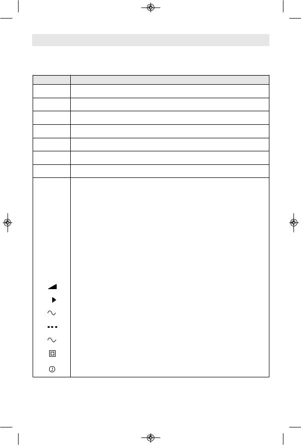
Symbols
IMPORTANT: Some of the following symbols may be used on your tool. Please study them and learn their meaning. Proper interpretation of these symbols will allow you to operate the tool better and safer.
Symbol |
Designation / Explanation |
V |
Volts (voltage) |
A |
Amperes (current) |
Hz |
Hertz (frequency, cycles per second) |
W |
Watt (power) |
kg |
Kilograms (weight) |
min |
Minutes (time) |
s |
Seconds (time) |
Diameter (size of drill bits, grinding wheels, etc.)
|
|
|
|||||
|
n0 |
No load speed (rotational speed at no load) |
|||||
|
|
n |
Rated speed (maximum attainable speed) |
||||
|
|
|
|
|
|
|
|
.../min |
Revolutions or reciprocation per minute (revolutions, strokes, surface speed, |
||||||
orbits etc. per minute) |
|||||||
|
|
|
|
|
|
||
|
|
|
|
||||
0 |
|
|
Off position (zero speed, zero torque...) |
||||
|
|
||||||
1, 2, 3, ... |
Selector settings (speed, torque or position settings. Higher number means |
||||||
I, II, III, |
greater speed) |
||||||
|
|
|
|
|
|
||
0 |
|
|
|
|
Infinitely variable selector with off (speed is increasing from 0 setting) |
||
|
|
|
|
|
|
|
|
|
|
|
|
|
|
Arrow (action in the direction of arrow) |
|
|
|
|
|
|
|
|
|
|
|
|
|
|
|
Alternating current (type or a characteristic of current) |
|
|
|
|
|
|
|
|
|
|
|
|
|
|
|
Direct current (type or a characteristic of current) |
|
|
|
|
|
|
|
||
|
|
|
|
|
|
|
|
|
|
|
|
|
|
Alternating or direct current (type or a characteristic of current) |
|
|
|
|
|
|
|
||
|
|
|
|
|
|
|
|
|
|
|
|
|
|
Class II construction (designates double insulated construction tools) |
|
|
|
|
|
|
|
|
|
|
|
|
|
|
|
Earthing terminal (grounding terminal) |
|
|
|
|
|
|
|
||
9
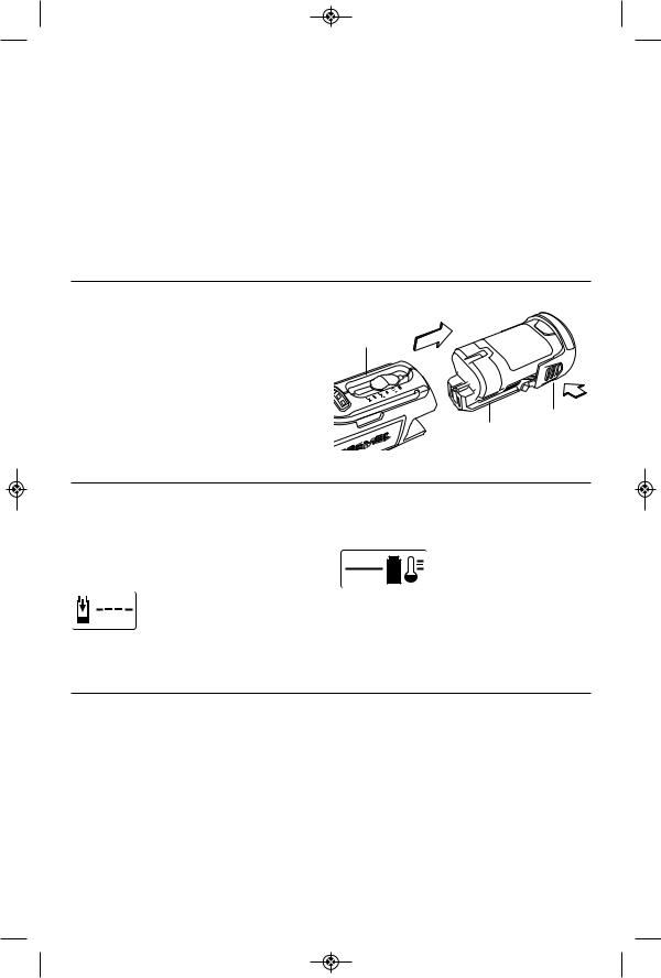
Functional Description and Specifications
Disconnect battery pack from tool before making any assembly, adjustments or changing accessories. Such preventive safety measures
reduce the risk of starting the tool accidentally.
Model 8220 Cordless Rotary Tool
|
VARIABLE SPEED |
|
ADJUSTER |
FUEL GAUGE |
|
|
BATTERY |
HANGER |
PACK |
ON/OFF SWITCH
SHAFT LOCK
BUTTON
BATTERY
RELEASE TABS
VENTILATION
OPENINGS
SHAFT |
COLLET |
|
WRENCH |
||
|
COLLET
|
COLLET |
|
EZ TWIST™ |
|
|
|
|||
|
|
INTEGRATED |
||
|
|
NUT |
|
|
|
|
WRENCH/NOSE CAP |
||
|
|
|
||
Model number |
8220 |
|
|
Charger |
876 |
|
|
Voltage rating |
10.8V/12V |
|
MAX |
Charge Time |
1 Hour |
60 Hz |
|
|
|||||||
Rated speed |
n 5,000 - 35,000/min |
Voltage rating |
120 V |
||||
Battery pack |
875, B812-01, B812-02, |
||||||
Collet capacities |
1/32, 1/16", 3/32", 1/8" |
||||||
|
|
|
|
|
and B812-03 |
||
|
|
|
|
11Capacity |
1.3 Ah, 1.5 Ah, or 2 Ah |
||
Assembly
Disconnect battery pack from tool before making any assembly, adjustments or changing accessories. Such preventive safety measures
reduce the risk of starting the tool accidentally.
SHAFT LOCK |
|
SHAFT LOCK |
BUTTON |
COLLET |
BUTTON |
|
NUT |
|
TO |
|
|
TIGHTEN |
|
|
 COLLET NUT COLLET TO
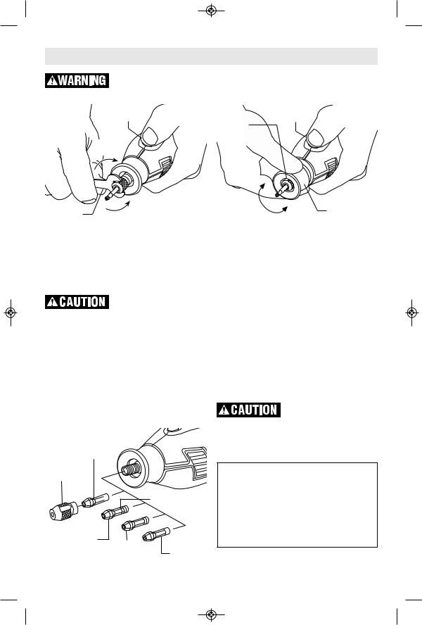
COLLETWRENCHNUT — To LOOSENloosen, first press shaft lock button and rotate the shaft by hand until the lock engages the shaft preventing further rotation. Your Dremel 8220 is equipped with a quick collet lock mechanism. This mechanism engages the output shaft in 8 separate locations on the shaft for easier operation.
Do not engage lock while the Rotary Tool is running.
With the shaft lock engaged use the collet wrench to loosen the collet nut if necessary. The collet nut must be loosely threaded on when inserting an accessory. Change accessories by inserting the new one into the collet as far as possible to minimize runout and
COLLETS — Four different size collets (see illus tration), to accommodate different shank sizes, are avail able for your Rotary Tool. To install a different collet, remove the collet nut and remove the old collet. Insert the unslotted
480
1/8" COLLET
COLLET
NUT
|
|
IDENTIFICATION |
|
|
|
RINGS |
|
481 |
|
|
|
3/32" |
482 |
483 |
|
COLLET |
|
||
1/16" |
1/32" |
|
|
|
|
||
|
COLLET |
COLLET |
|
|
|
|
12 |
|
TO |
EZ TWIST™ |
TO |
INTEGRATED |
|
TIGHTEN |
LOOSEN |
WRENCH/NOSE CAP |
unbalance. With the shaft lock engaged, finger |
||
tighten the collet nut until the accessory shank |
||
is gripped by the collet. |
Avoid excessive |
|
tightening of the collet nut when there is no bit inserted.
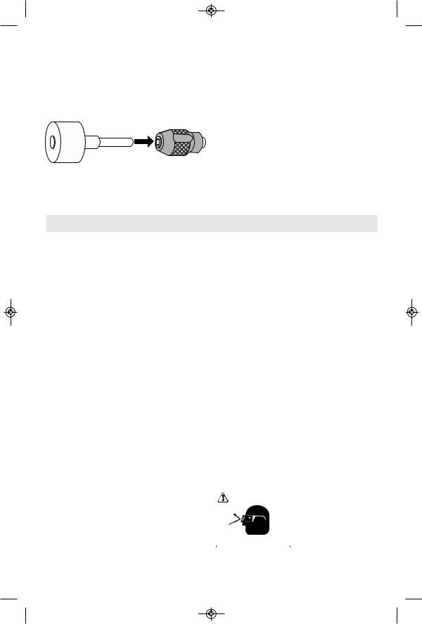
EZ TWIST™ INTEGRATED
WRENCH/NOSE CAP
The nose cap of your tool has an integrated wrench allowing you to loosen and tighten the collet nut without the use of the standard collet wrench. Unscrew the nose cap from the tool, line-up steel insert on inside of cap with collet nut. With the shaft lock engaged twist nose cap clockwise to tighten, and counter-clockwise to loosen.
end of the collet in the hole in the end of the tool shaft. Replace collet nut on the shaft.
Always use the collet which matches the shank size of the accessory you plan to use. Never
force a larger diameter shank into a collet. Note: Most rotary tool kits do not include all four collets sizes.
COLLET IDENTIFICATION CHART
Collet sizes can be identified by the rings on the back end of collet.
1/32" Collet has one (1) ring. 1/16" Collet has two (2) rings. 3/32" Collet has three (3) rings.
1/8" Collet has no rings. (Included in most tool kits on the tool)
FIxING STUCK COLLETS – It is possible for a collet to get stuck within the collet nut especially if a collet nut is tightened onto the tool without a bit in place. If this happens, the collet can be removed from the collet nut by pushing the shank of an accessory into the hole in the collet nut. This should cause the collet to pop out of the collet nut.
BALANCING ACCESSORIES — For precision work, it is important that all accessories be in good balance (much the same as the tires on your automobile). To true up or balance an
accessory, slightly loosen collet nut and give the accessory or collet a 1/4 turn. Re ightent collet nut and run the Rotary Tool. You should be able to tell by the sound and feel if your accessory is running in balance. Continue adjusting in this fashion until best balance is achieved. To maintain balance on abrasive wheel points, before each use, with the wheel point secured in the collet, turn on the Rotary Tool and run the 415 Dressing Stone lightly against the revolving wheel point. This removes high spots and trues up the wheel point for good balance.
The hanger is provided for the use of hanging your tool while using the flex-shaft or for storage. If you do not use the hanger, snap it back into place so it will be out of the way while the tool is in use.
Operating Instructions
Dremel 8220 |
drill is a low-speed, high torque tool; the Rotary |
|||||
Thank you for purchasing the Dremel 8220. This |
Tool is just the opposite – a high-speed, low |
|||||
product was designed by the many Dremel |
torque tool. The major difference to the user is |
|||||
users who passionately use their rotary tools |
that in the high speed tools, the speed combined |
|||||
daily. This tool was designed to give you the |
with the acces sory mounted in the collet does the |
|||||
ultimate performance when working on projects. |
work. You don’t apply pressure to the tool, but |
|||||
The Dremel 8220 is one of the MOST versatile |
simply hold and guide it. In the low speed tools, |
|||||
cordless rotary tool available today. It has a wide |
you not only guide the tool, but also apply |
|||||
speed range including a high performance motor |
pressure to it, as you do, for example, when drilling |
|||||
that allows the tool to maintain its speed under |
a hole. |
|
|
|
|
|
load. The design of the tool also contains plenty |
It is this high speed, along with its compact size |
|||||
of soft grip so the tool can be held comfortably in |
and wide variety of special accessories and |
|||||
many positions. The quick collet lock mechanism |
attachments, that makes the Rotary Tool differ ent |
|||||
makes locking the output shaft easier for |
from other tools. The speed enables it to do jobs |
|||||
changing accessories. You will appreciate the |
low speed tools cannot do, such as cutting |
|||||
many applications that the Dremel 8220 can |
hardened steel, en graving glass, etc. |
|
|
|||
easily tackle. |
Getting the most out of your Rotary Tool is a |
|||||
Rotary Tool Introduction |
matter of learning how to let this speed work for |
|||||
The Rotary Tool has a small, powerful electric |
you. To learn about more uses and the versatility |
|||||
motor, is comfort able in the hand, and is made to |
of Dremel accessories and attachments refer to |
|||||
accept a large variety of accessories including |
this Owner's Manual or check our website at |
|||||
abrasive wheels, drill bits, wire brushes, |
www.Dremel.com. |
|
|
|
|
|
polishers, engraving cutters, router bits, cutting |
Using the Rotary Tool |
|
|
|||
wheels and attachments. Accessories come in a |
The first step in learning to use the Rotary Tool is |
|||||
variety of shapes and permit you to do a number |
to get the “feel” of it. Hold it in your hand and feel |
|||||
of different jobs. As you be come familiar with the |
its weight and balance. Feel the taper of the |
|||||
range of accessories and their uses, you will |
housing. |
|
|
|
|
|
learn just how versatile the Rotary Tool is. You’ll |
|
Always |
hold |
the |
tool |
|
see dozens of uses you hadn’t thought of before. |
WARNING |
|||||
away from your face. |
||||||
The real secret of the Rotary Tool is its speed. To |
|
Accessories |
can |
be |
||
understand the advantages of its high speed, you |
|
damaged |
during |
|||
have to know that the standard portable electric |
|
handling, and can fly |
||||
drill runs at speeds up to 2,800 revolutions per |
|
apart as they come up to |
||||
Wear Eye Protection |
||||||
minute. The Rotary Tool operates at speeds up to |
|
speed. |
This |
is |
not |
|
|
||||||
30,000 revolutions per minute. The typical electric |
common, but it does happen. |
|
|
|
||
13
Whenever you hold the tool, be careful not to cover the air vents with your hand. This
blocks the air flow and causes the motor to overheat.
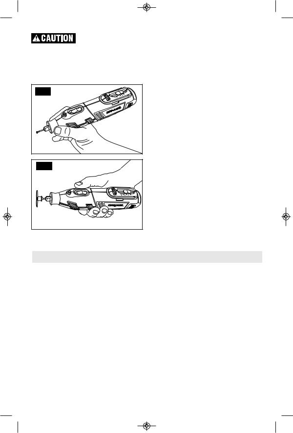
For best control in close work, grip the Rotary Tool like a pencil between your thumb and forefinger (Figure A).
FIG. A |
FIG. B |
The “Golf Grip” method of holding the tool can be used for more aggressive operations such as grinding a flat surface or using cutoff wheels (Figure B).
Practice on scrap materials first to see how the Rotary Tool's high speed action performs. Keep in mind that the work is done by the speed of the tool and by the accessory in the collet. You should not lean on or push the tool during use.
Instead, lower the spinning accessory lightly to the work and allow it to touch the point at which you want cutting (or sanding or etching, etc.) to begin. Con centrate on guiding the tool over the work using very little pressure from your hand. Allow the accessory to do the work.
Usually, it is best to make a series of passes with the tool rather than attempt to do all the work in one pass. To make a cut, for example, pass the tool back and forth over the work, much as you would a small paint brush. Cut a little material on each pass until you reach the desired depth. For most work, the gentle touch is best. With it, you have the best control, are less likely to make errors, and will get the most effi cient work out of the accessory.
Questions or Problems? Call 1-800-437-3635
or check our website at www.Dremel.com
Operating Speeds
To select the right speed for each job, use a practice piece of material.
SLIDE "ON/OFF" SWITCH
The tool is switched "ON" by the slide switch located on the topside of the motor housing. TO TURN THE TOOL "ON", slide the switch button forward.
TO TURN THE TOOL "OFF", slide the switch button backward.
HIGH PERFORMANCE MOTOR
Your tool is equipped with a high performance rotary tool motor. This motor expands the versatility of the rotary tool by driving additional attachments such as the Dremel Multi-Saw and Dremel Planer.
ELECTRONIC MONITORING
Your tool is equipped with an internal electronic monitoring system that provides a “soft start”, 14
which will reduce the stresses that occur from a high torque start. The system also helps to maximize motor and battery performance by by limiting the current to the tool when overload and stall conditions occur. The motor and battery pack are protected by limiting the current to the motor in these situations.
VARIABLE SPEED ADJUSTER
Your tool is equipped with a variable speed adjuster. The speed may be adjusted during operation by sliding the adjuster back or forth between any one of the settings.
You can refer to the charts on pages 27 – 30 to determine the proper speed, based on the materi al being worked and the type of accessory being used. These charts enable you to select both the correct acces sory and the optimum speed at a glance.
The speed of Rotary Tool is controlled by setting this adjuster on the housing.
|
|
VARIABLE SPEED |
|
|
ADJUSTER |
|
|
|
Settings for Approximate Revolutions. |
||
|
|
|
Switch Setting |
Speed Range |
|
5 |
|
15,000-7,000 RPM |
*10 |
|
17,000-10,000 RPM |
15 |
|
13,000-17,000 RPM |
20 |
|
18,000-23,000 RPM |
25 |
|
23,000-27,000 RPM |
30 |
|
28,000-35,000 RPM |
* Wire Brush Setting. |
|
|
30 |
|
|
20 |
|
|
10 |
|
|
Needs for Slower Speeds
Certain materials, however, (some plastics and precious metals, for ex ample) require a relatively slow speed because at high speed the friction of the accessory generates heat and may cause damage to the material.
Slow speeds (15,000 RPM or less) usually are best for polishing operations employing the felt polishing ac ces sories. They may also be best for working on deli cate projects as “eggery” work, delicate wood carving and fragile model parts. All brushing applications require lower speeds to avoid wire discharge from the holder.
Higher speeds are better for carving, cutting, routing, shaping, cutting dadoes or rabbets in wood.
Hardwoods, metals and glass require high speed operation, and drilling should also be done at high speeds.
Many applications and accessories in our line will provide the best performance at full speed, but for certain materials, applications, and accessories, you need slower speeds, which is the reason our variable speed models are available.
To aid you in determining the optimum operational speed for differ ent materials and different accessories, we have construct ed a series of tables that appear on pages 27 – 30. By referring to these tables, you can discover the recommended speeds for each type of accessory. Look these tables over and become familiar with them.
Ultimately, the best way to determine the correct speed for work on any material is to practice for a few minutes on a piece of scrap, even after referring to the chart. You can quickly learn that a slower or faster speed is more effective just by observing what hap pens as you make a pass or two at different speeds. When working with plastic, for example, start at a slow rate of speed and increase the speed until you observe that the plastic is melting at the point of contact. Then reduce the speed slight yl to get the optimum working speed.
Some rules of thumb in regard to speed:
1. Plastic and other materials that melt at low temperatures should be cut at low speeds.
2. Polishing, buffing and cleaning with any type of bristle brush must be done at speeds not greater than 15,000 RPM to prevent damage to the brush from bristles flying toward operator.
3. Wood should be cut at high speed.
4. Iron or steel should be cut at high speed. If a high speed steel cutter starts to chatter — this normally means it is running too slow.
5. Aluminum, copper alloys, lead alloys, zinc alloys and tin may be cut at various speeds, depending on the type of cutting being done. Use paraffin or other suitable lubricant on the cutter to prevent the cut material from adhering to the cutter teeth.
Increasing the pressure on the tool is not the answer when it is not performing as you think it should. Perhaps you should be using a different accessory, and perhaps an adjustment in speed would solve the problem. Leaning on the tool does not help.
Let speed do the work!
All Dremel Rotary Tool attachments are compatible with your tool, but you may experience reduced run times on the battery when using certain attachments.
Use only Dremel®, high-performance accessories.
15
FUEL GAUGE
This tool is equipped with a fuel gauge that tells you how much charge your battery has. A fully charged battery is indicated when all three LED lights are illuminated. As the battery discharges, the lights will turn off one by one until only one light is on. When the last light starts "flashing", the battery is almost empty. When the battery is dead, the tool will automatically turn off. This will be a sudden stop as opposed to a gradual winding down of the tool. Simply recharge the battery and reuse.
3 lights - 100% charge remaining
2 lights – 50% charge remaining
1 light - 25% charge remaining
1 "flashing" light - tool is about to shut off
3 “side to side” lights – battery charge is too low to run tool. Recharge the battery.
3 “flashing” lights – battery is too hot or too cold for use. Turn tool off and let battery return to normal operating temperature before resuming use.
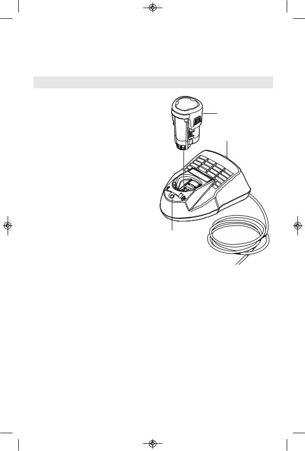
INSERTING AND RELEASING
BATTERy PACK
Release battery pack from tool by pressing on HOUSING both sides of the battery release tabs and pull
away from housing.
To insert battery, align battery and slide battery pack into tool until it locks into position. Do not force.
BATTERY BATTERY RELEASE
PACK TABS
CHARGER INDICATORS, SyMBOLS
AND MEANING
If the indicator lights are “OFF”, the charger is not receiving power from power supply outlet.
If the green indicator light is “BLINKING”, the battery pack is being fast-charged. Fastll automatically stop when the
battery pack is fully charged.
Fast-charging means that the battery will be fully charged in one hour.
If the green indicator light is "ON", the charger is plugged in but the battery erted, or the battery pack is
fully charged, or the battery pack is too hot or cold for fast-charging. The charger will automatically switch to fast-charging once a suitable temperature is reached.
IMPORTANT CHARGING NOTES |
charge may mean that the battery pack is |
|
1. The charger was designed to fast charge |
nearing the end of its life and should be replaced. |
|
the battery only when the battery temperature |
3. Remember to unplug charger during storage |
|
is between 32˚F (0˚C) and 113˚F (45˚C). If the |
||
period. |
||
battery pack is too hot or too cold, the charger |
||
4. If battery does not charge properly: |
||
will not fast charge the battery. (This may |
||
happen if the battery pack is hot from heavy |
a. Check for voltage at outlet by plugging in |
|
use). When the battery temperature returns to |
some other electrical device. |
|
between 32˚F (0˚C) and 113˚F (45˚C), the |
b. Check to see if outlet is connected to a |
|
charger will automatically begin charging. |
||
light switch which turns power “off” when lights |
||
2. A substantial drop in operating time per |
||
16 are turned off. |
c.Check battery pack terminals for dirt. Clean with cotton swab and alcohol if necessary.
d.If you still do not get proper charging,
take or send tool, battery pack and charger to your local Dremel Service Center.
Note: Use of chargers or battery packs not sold by Dremel will void the warranty.
Charging Battery Pack
876 1-HOUR CHARGER |
|
Plug charger cord into your standard power |
|
outlet, then insert battery pack into charger. |
|
The charger’s green indicator light will begin to |
|
“BLINK”. This indicates that the battery is |
|
receiving a fast charge. Fast-charging will |
|
automatically stop when the battery pack is |
|
fully charged. |
|
When the indicator light stops “BLINKING” |
|
(and becomes a steady green light) fast |
|
charging is complete. |
|
The battery pack may be used even though |
|
the light may still be blinking. The light may |
|
require more time to stop blinking depending |
|
on temperature. |
|
The purpose of the green light is to indicate |
|
that the battery pack is fast-charging. It does |
|
not indicate the exact point of full charge. |
|
The light will stop blinking in less time if the |
|
battery pack was not completely discharged. |
|
When charging several batteries in sequence, |
GREEN |
the charge time may slightly increase. |
LIGHT |
When the battery pack is fully charged, |
|
unplug the charger (unless you're charging |
|
another battery pack) and slip the battery |
|
pack back into the tool. |
|
BATTERY
PACK
CHARGER
17

|
|
|
|
|
|
|
|
|
|
Maintenance |
|
|
|
|
|
Service |
|
recommend it be examined every six months. |
||
|
|
NO |
USER |
Only a genuine Dremel replacement motor |
||
|
|
SERVICEABLE PARTS |
specially designed for your tool should be |
|||
|
|
|||||
INSIDE. Preventive |
maintenance |
used. |
Cleaning |
|||
performed by un au thorized personnel |
|
|||||
may result in misplacing of internal wires |
|
|
To avoid accidents, |
|||
|
|
|||||
and components which could cause |
|
|
always disconnect the |
|||
|
|
|||||
serious hazard. We recom mend that all tool |
tool and/or charger from the power supply |
|||||
service be performed by a Dremel Service |
before cleaning. The tool may be cleaned |
|||||
Center. SERVICE MEN: Disconnect tool and/or |
most effectively with com pressed dry air. |
|||||
charger from power source before servicing. |
Always wear safety goggles when |
|||||
|
BATTERIES |
|
cleaning tools with compressed air. |
|||
Be alert for battery packs that are nearing |
Ventilation openings and switch levers must |
|||||
their end of life. If you notice decreased |
be kept clean and free of foreign matter. Do |
|||||
tool performance or significantly shorter |
not attempt to clean by inserting pointed |
|||||
running time between charges then it is time |
objects through opening. |
|||||
to replace the battery pack. Failure to do so |
|
|
Certain cleaning agents |
|||
can cause the tool to operate improperly or |
|
|
||||
damage the charger. |
|
|
|
and solvents damage |
||
|
|
|
||||
|
D.C. MOTORS |
plastic parts. Some of these are: gasoline, |
||||
The motor in your tool has been engineered |
car bon tetrachloride, chlorinated cleaning |
|
solvents, ammonia and household detergents |
||
for many hours of dependable service. To |
||
that contain ammonia. |
||
maintain peak efficiency of the motor, we |
||
|
Extension Cords
|
|
If an extension cord is |
RECOMMENDED SIZES OF ExTENSION CORDS |
|||||||||
|
|
|||||||||||
|
|
necessary, a cord with |
120 VOLT ALTERNATING CURRENT TOOLS |
|||||||||
|
|
|||||||||||
adequate size conductors that is capable |
|
|
|
|
|
|
|
|
|
|||
of carrying the current necessary for your |
Tool’s |
Cord Size in A.W.G. |
Wire Sizes in mm2 |
|||||||||
tool must be used. This will prevent |
Ampere |
Cord Length in Feet |
Cord Length in Meters |
|||||||||
excessive voltage drop, loss of power or |
Rating |
|
|
|
|
|
|
|
|
|||
25 |
50 |
100 |
150 |
15 |
30 |
60 |
120 |
|||||
overheating. Grounded tools must use 3-wire |
|
|||||||||||
extension cords that have 3-prong plugs and |
3-6 |
18 |
16 |
16 |
14 |
0.75 |
0.75 |
1.5 |
2.5 |
|||
receptacles. |
6-8 |
18 |
16 |
14 |
12 |
0.75 |
1.0 |
2.5 |
4.0 |
|||
NOTE: The smaller the gauge number, the |
8-10 |
18 |
16 |
14 |
12 |
0.75 |
1.0 |
2.5 |
4.0 |
|||
10-12 |
16 |
16 |
14 |
12 |
1.0 |
2.5 |
4.0 |
– |
||||
higher the cord capacity. |
12-16 |
14 |
12 |
– |
– |
– |
– |
– |
– |
|||
18
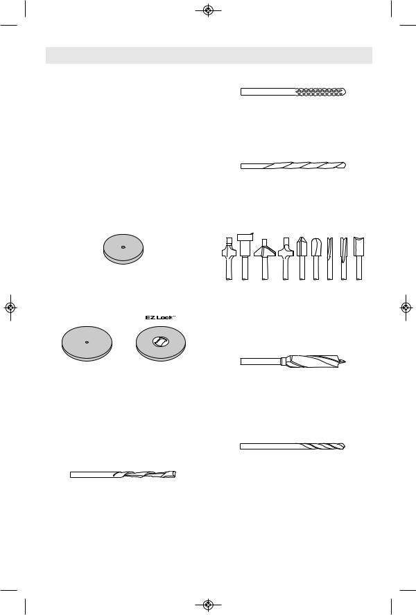
Dremel Accessories
Use only Dremel®, high-performance accessories. Other accessories are not designed for this tool and may lead to personal injury or property damage.
Store accessories in a dry and temperate environment to avoid corrosion and deterioration.
The number and variety of accessories for the Rotary Tool are almost limitless. There is a category suited to almost any job you might have to do and a variety of sizes and shapes within each category which en ables you to get the perfect accessory for every need.
COLLETS
If you expect to use a variety of accessories, we recommend that in the beginning you purchase a complete set of four collets. Store these so that you will have the proper size of collet for any accessory or drill bit you want to use. Currently, the 1/8", 3/32",1/32" and
1/16" collets accommodate all of the available Dremel accessories. 1/8" collets are included in most rotary tool kits.
MANDRELS
A mandrel is a shank with a threaded or screw head, which are required when you use polishing accessories, cutting wheels, sanding discs, and pol ish ing points. The reason mandrels are used is that sanding discs, cutting wheels and similar accesso ries must be replaced frequently. The mandrel is a permanent shank, allowing you to replace only the worn head when necessary, thus saving the expense of replacing the shaft each time.
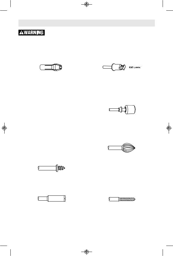
Screw Mandrel No 401
This is a screw mandrel used with the felt polishing tip and felt polishing wheels. 1/8" shank.
Small Screw Mandrel No 402
This is a mandrel with a small screw at its tip, and is used with emery and fiberglass cutting wheels, sanding discs and polishing wheels. 1/8" shank.
EZ Lock Mandrel No 402
The Dremel EZ Lock makes accessory changes easy as PULL - TWIST - RELEASE. The one-piece mandrel design simplifies the process of changing cutting wheels, buffs and detail abrasive brushes (EZ Lock compatible accessories).
EZ Drum™ Mandrel No EZ407SA
The Dremel EZ Drum makes accessory changes easy as PULL - INSERT - PRESS DOWN. The one-piece mandrel design simplifies the process of changing sanding bands.
High Speed Cutters
Available in many shapes, high speed cutters are used in carving, cutting and slotting in wood, plastics and soft metals such as aluminum, copper and brass. These are the accessories to use for freehand routing or carving in wood or plastic, and for precision cutting. Made of high quality steel. 1/8" shank.
Tungsten Carbide Cutters
These are tough, long-lived cutters for use on hard ened steel, fired ceramics and other very hard ma terials. They can be used for engraving on tools and garden equipment. 1/8" shanks.
19
Dremel Accessories (Continued)
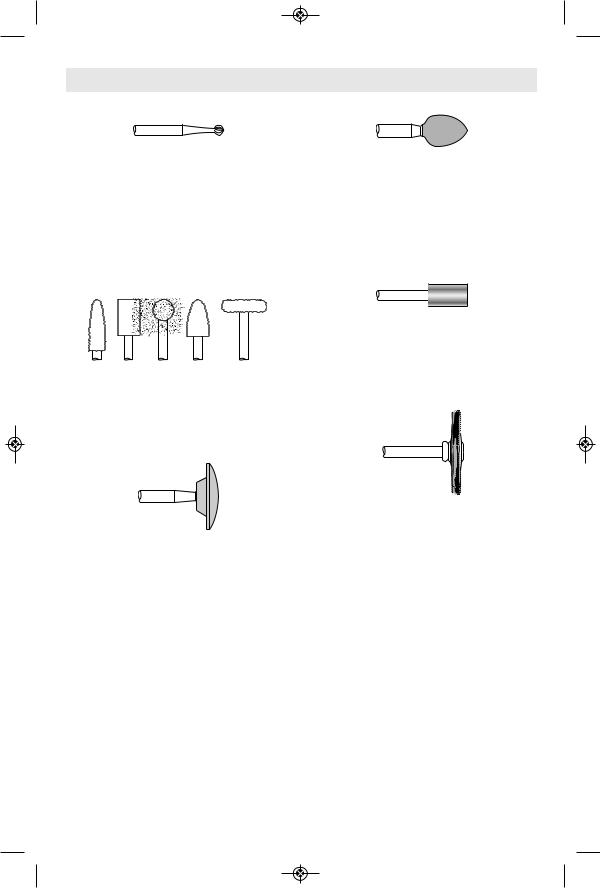
Engraving Cutters
This group has a wide variety of sizes and shapes, and are made for intricate work on ceramics (greenware), wood carvings, jewelry and scrimshaw. They often are used in making complicat ed printed circuit boards. They should not be used on steel and other very hard materials but are excellent on wood, plastic and soft metals. 1/8" shank.
Structured Tooth Tungsten Carbide Cutters
Fast cutting, needle-sharp teeth for greater material removal with minimum loading. Use on fiberglass, wood, plastic, epoxy and rubber. 1/8" shank.
Silicon Carbide Grinding Stones (blue/green)
Tougher than aluminum oxide points, these are made es pecially for use on hard materials such as glass and ce ramics. Typical uses might be the removal of stilt marks and excess glaze on ceramics and engraving on glass. 1/8" shank.
Diamond Wheel Points
Excellent for fine detail work on wood, jade, ceramic, glass and other hard material. Bits are covered with diamond particles. 1/8" shanks. (Not recommended for drilling)
Aluminum Oxide Grinding Stones (red/brown)
Round, pointed, flat — you name the shape and there is one available in this category. These are made of aluminum oxide and cover virtually every possible kind of grinding application. Use them for sharpening lawn mower blades, screwdriver tips, knives, scissors, chisels and other cutting tools. Use to remove flash from metal castings, deburring any metal after cutting, smoothing welded joints, grinding off rivets and re mov ngi rust. These grinding stones can be resharped with a dressing stone. In machine shops, high speed drills and cut erst normally are ground with aluminum oxide wheels. 1/8" shank.
Wire Brushes
Three different shapes of wire brushes are available. For best results wire brushes should be used at speeds not greater than 15,000 RPM. Refer to Operating Speeds section for proper tool speed setting. The three shapes come in three different materials: stainless steel, brass and carbon wire. The stainless steel perform well on pewter, aluminum, stainless steel, and other metals, without leaving "after-rust". Brass brushes are non sparking, and softer than steel; making them good for use on soft metal like gold, cooper and brass. The carbon wire brushes are good for general purpose cleaning.
20
Dremel Accessories (Continued)
Bristle Brushes
These are excellent cleaning tools on silverware, jew elry and antiques. The three shapes make it possible to get into tight corners and other difficult places. Bristle brushes can be used with polishing compound for faster cleaning or polishing.
INCORRECT:
Excessive pressure can cause wire breakage.
CORRECT: Wire tips doing the work.
Brushing Pressure
1. Remember, the tips of a wire brush do the work. Operate the brush with the lightest pressure so only the tips of the wire come in contact with the work.
2. If heavier pressures are used, the wires will be overstressed, resulting in a wiping action; and if this is continued, the life of the brush will be shortened due to wire fatigue.
3. Apply the brush to the work in such a way that as much of the brush face as possible is in full contact with the work. Applying the side or edge of the brush to the work will result in wire breakage and shortened brush life.
Polishing Accessories
These include an impregnated polishing point and an impregnated polishing wheel for bringing metal sur faces to smooth finish; a felt polishing tip and felt polish ngi wheel, and cloth polishing wheel, all used for polishing plastics, metals, jewelry and small parts. Also included in this group is a polishing compound (No. 421) for use with the felt and cloth polishers.
Polishing points make a very smooth surface, but a high luster is obtained using felt or cloth wheels and polishing compound.
For best results polishing accessories should be used at speeds not greater than 15,000 RPM.
No polishing compound is needed when using the 425 Polishing Wheel.
Aluminum Oxide Abrasive Wheels
Use to remove paint, deburr metal, polish stainless steel and other metals. Available in medium grit. 1/8" shank.
Sanding Accessories
Sanding discs in fine, medium and coarse grades are made to fit mandrel No. 402 and EZ407. They can be used for nearly any small sanding job you might have, from model making to fine furniture finish ngi. In addition, there is the drum sander, a tiny drum which fits into the Rotary Tool and makes it possible to shape wood, smooth fiberglass, sand inside curves and other diffi-
21
Dremel Accessories (Continued)
cult places, and other sanding jobs. You replace the sanding bands on the drum as they become worn and lose their grit. Bands come in fine medium and coarse grades. Flapwheels grind and polish flat or contoured surfaces. They are used most effectively as a finishing sander after heavier surface sanding and material removal is completed. Flapwheels come in fine and coarse grades. Buffs are a great finishing accessory for cleaning and light sanding. They work effectively on metal, glass, wood, aluminum and plastics. Coarse and medium buffs are sold together. All buffs are sold individually.
Do not exceed 15,000 RPM in speed. 1/8" shank.
Grinding Wheel
Use for deburring, removing rust, and general purpose grinding. Use with Mandrel #402.
Tile Cutting Bit
Cuts ceramic wall tile, cement board, and plaster. Use with Dremel No 565/566 Cutting Guide attachment.
Spiral Cutting Bit
Cuts through all types of wood and wood composites. Use with Dremel No 565/566 Cutting Guide attachment.
High Speed Router Bits
For routing, inlaying, and mortising in wood and other soft materials. Use with Dremel No. 335 Router attachment and No. 231 Shaper/Router table.
Cutting Wheels
These thin discs of emery or fiberglass are used for slicing, cutting off and similar operations. Use them for cutting off frozen bolt heads and nuts, or to reslot a screw head which has become so damaged that the screwdriver won’t work in it. Fine for cutting BX cable, small rods, tubing, cable and cutting rectangular holes in sheet metal.
Drywall Cutting Bit
Gives you fast, clean cuts in drywall. Use with Dremel No 565/566 Cutting Guide attachment.
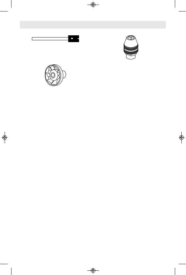
Brad Point Drill Bits
Titanium coated brad points stay on center and begin drilling immediately. For use on wood. Size 1/8”, 5/32”, 3/16”, ¼” . 1/8” shank.
HSS Drill Bits
HSS drill bit for use in metal and plastic. Size 1/8”, 7/64”, 3/32”, 5/64”, 1/16”, 3/64”, 1/32”. Shank size matches the drill bit size. Different collet size (481, 482, 483) or Dremel chuck (4486) required according to drill bit being used.
22
Dremel Accessories (Continued)
Glass Drill Bits
Diamond tipped drill bits for use on glass and ceramic wall tile. Lubricant included.
Collet Fan
Blows dust away for greater visibility to work piece. Great for sanding, engraving and carving. Do not use dust blower to stop or slow down the tool. Do not contact dust blower with fingers or workpiece during use.
Dremel Chuck
This chuck allows you to quickly and easily change accessories on Dremel Rotary Tools without changing collets. Accepts accessories with 1/32” - 1/8” shank. Read instruction manual. Insert and securely tighten the shank of the accessory well within the jaws of the chuck.
23
Replacing Screw Mandrel Accessories
Mandrel No. 401 is used with the felt polishing tip and wheels. Thread the tip on to the screw carefully. The felt tip must thread
Mandrel N° 402 has a small screw at its tip, and is used with emery cutting wheels and sanding discs. Higher speeds, usually
To replace a band on the Drum Sander, loosen the screw without removing it to contract the drum then slide the old band off. Slide the new sanding band on and then expand the drum by tightening the screw once again.
down straight on the screw Mandrel, and be turned all the way to the collar.
maximum, are best for most work, including cutting steel. Which is shown here.
Before each use, check to make certain that all components are assembled to accessory
shank and that the drum is sufficiently expanded to secure the band during use. If sanding band is loose on the drum during operation it may “fly” off and strike you or bystanders.
24

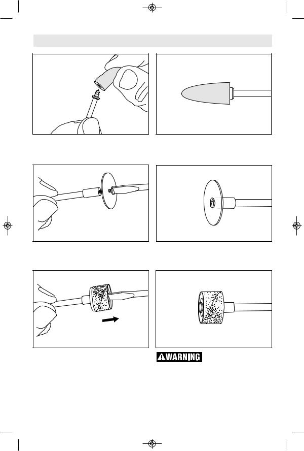
EZ Lock™ Operating Instructions
EZ Lock™ Mandrel No. EZ402 has a spring loaded sleeve and is used with cutting wheels, abrasive buffs and polishing cloth.
Always make sure the rotary tool is “OFF” and disconnect the plug from the power
source or the battery pack from the tool before changing accessories. Such preventative safety measures reduce the risk of starting the power tool accidentally.
Always make sure accessory is properly seated on mandrel before use. Incorrect seating of accessory on mandrel may lead to personal injury or property damage.
To load accessory:
1. Place EZ Lock™ mandrel into collet as deep as possible and tighten collet nut. Note: There is a blue spacer that will bottom out on the collet nut, setting the mandrel to the correct depth. When using with Dremel chuck, back the mandrel out slightly before tightening.
2. Pull spring-loaded sleeve DOWN towards tool with one hand and hold. You can brace the tool on the body or work-bench for extra leverage (Fig. 1).
3. With the other hand, align bowtie shape on cut-off wheel with mandrel and make sure metal insert is facing away from the tool (Fig. 2).
4. Place wheel on the mandrel to a point just below the bowtie on the mandrel and twist 90 degrees until the bowtie shape on the wheel aligns with the sleeve. Release sleeve. Wheel should lock in place (Fig. 3).
5. When mounting sanding and polishing accessories, align bowtie with metal insert on bottom of accessory (Fig. 4 & 5).
To check for proper seating, hold shaft lock button and twist accessory. Accessory will not be able to rotate on mandrel. To unload accessory:
1. Pull spring-loaded sleeve DOWN toward tool with one hand (Fig. 1).
2. Hold sleeve down while twisting accessory
90 degrees.
3. Remove accessory.
During use
Avoid damage to EZ lock™ mandrel by not letting it contact the workpiece.
FIG. 1
FIG. 2
FIG. 3
FIG. 4 |
FIG. 5 |
25
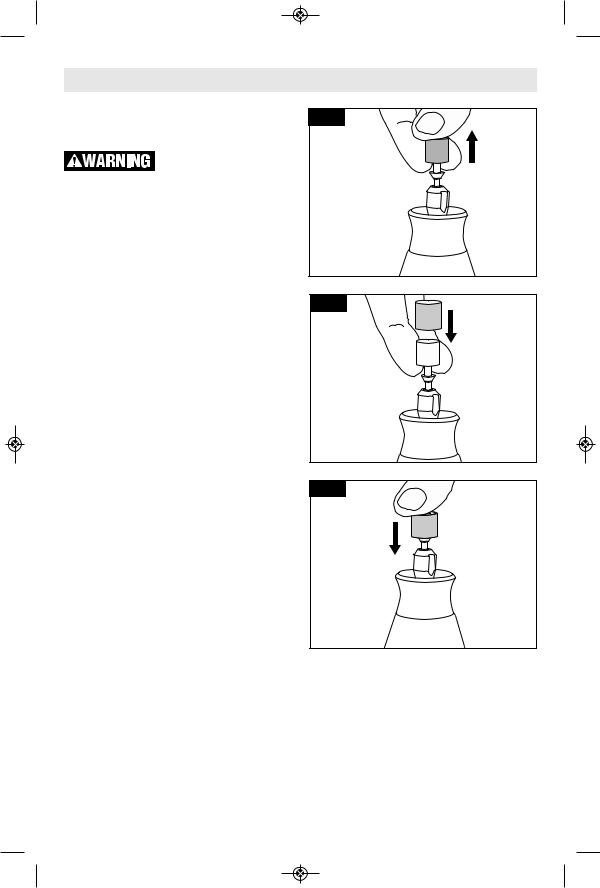
EZ Drum™ Operating Instructions
EZ Drum™ Mandrel No. EZ407SA has a spring loaded sleeve and is used with sanding bands. Always make sure the rotary tool is “OFF” and disconnect the plug from the power
source or the battery pack from the tool before changing accessories. Such preventative safety measures reduce the risk of starting the power tool accidentally.
Always make sure accessory is properly seated on mandrel before use. Incorrect seating of accessory on mandrel may lead to personal injury or property damage.
To load accessory:
1. As indicated, place two fingers underneath the mandrel and pull firmly up. This will place the EZ Drum™ in the "unlocked" position (Fig. 1).
2. Keeping two fingers beneath the mandrel, slide the sanding band down until the entire blue mandrel is covered (Fig. 2).
3. To return to "locked" position, press firmly down on the top of the mandrel (Fig. 3).
Removing the sanding band on the mandrel:
1. Place two fingers underneath the mandrel and pull firmly up. This will place the EZ Drum™ in the "unlocked" position (Fig. 1).
2. Sanding band will now easily slide off mandrel (Fig. 2). Do not squeeze sanding band when removing from EZ Drum™ mandrel. This can lead to rubber band pulling off mandrel and becoming inoperable.
FIG. 1
FIG. 2
FIG. 3
26
Speed Settings
Note: Each number settings listed in the speed charts = x 1,000 RPM
* Speed for light cuts, Caution - burning on deep grooves.
• Depending on cutting direction relative to grain.
|
|
|
High Speed Cutters |
|
|
|
||
Catalog |
Soft |
Hard |
Laminates |
Steel |
Aluminum, |
Shell/ |
Ceramic |
Glass |
Number |
Wood Wood |
/Plastics |
|
Brass, etc. |
Stone |
|
|
|
100, 121, 131 |
25-35 25-35 |
12-17 |
12-17 |
18-24 |
- |
- |
- |
|
114,124, 134, 144 |
25-35 12-17 |
9-11 |
12-17 |
12-17 |
- |
- |
- |
|
118, 190, 191, 192, |
25-35 |
25-35 |
9-11 |
12-17 |
25-35 |
- |
- |
- |
193, 194 |
|
|
|
|
|
|
|
|
116, 117, 125, 196 |
25-35 12-17 |
9-11 |
12-17 |
12-17 |
- |
- |
- |
|
115 |
25-35 |
25-35 |
9-11 |
12-17 |
12-17 |
- |
- |
- |
198, 199 |
25-35 |
18-24 |
9-11 |
12-17 |
12-17 |
- |
- |
- |
|
|
|
Engraving Cutters |
|
|
|
||
Catalog |
Soft |
Hard |
Laminates |
Steel |
Aluminum, |
Shell/ |
Ceramic |
Glass |
Number |
Wood |
Wood |
/Plastics |
Brass, etc. |
Stone |
|||
105, 108 |
25-35 |
25-35 |
18-24 |
9-11 |
12-17 |
- |
- |
- |
106, 107, 109, 110 |
25-35 |
25-35 |
12-17 |
9-11 |
12-17 |
- |
- |
- |
111 |
25-35* 25-35* |
18-24* |
9-11 |
12-17 |
- |
- |
- |
|
112, 113 |
25-35* 25-35* |
12-17* |
9-11 |
12-17 |
- |
- |
- |
|
|
|
|
|
|
|
|
|
|
|
|
Diamond Wheel Points |
|
|
|
|||
Catalog |
Soft |
Hard |
Laminates |
Steel |
Aluminum, |
Shell/ |
Ceramic |
Glass |
Number |
Wood |
Wood |
/Plastics |
Brass, etc. |
Stone |
|||
7103, 7105, 7117, |
25-35 |
18-24 |
- |
- |
- |
25-35 |
25-35 |
25-35 |
7120, 7122, 7123, |
||||||||
7134, 7144 |
|
|
|
|
|
|
|
|
|
|
|
|
|
|
|
|
|
|
|
|
|
|
|
|
|
|
|
|
Structured Tooth Tungsten Carbide Cutters |
|
|
||||||
Catalog |
Soft |
Hard |
Laminates |
Steel |
Aluminum, |
Shell/ |
Ceramic |
Glass |
|
Number |
Wood |
Wood |
/Plastics |
Brass, etc. |
Stone |
||||
9931, 9932, 9933, |
25-35 |
18-24 |
9-11 |
- |
12-17 |
- |
- |
- |
|
9934, 9935, 9936 |
|||||||||
|
|
|
|
|
|
|
|
||
|
|
|
|
|
|
|
|
|
|
27
Speed Settings (Continued)
Note: Each number settings listed in the speed charts = x 1,000 RPM
* Speed for light cuts, Caution - burning on deep grooves.
• Depending on cutting direction relative to grain.
|
|
|
|
|
|
|||
|
|
Tungsten Carbide Cutters |
|
|
|
|||
Catalog |
Soft |
Hard |
Laminates |
Steel |
Aluminum, |
Shell/ |
Ceramic |
Glass |
Number |
Wood |
Wood |
/Plastics |
Brass, etc. |
Stone |
|||
9901, 9902, 9903, |
25-35 |
18-24 |
9-11 |
25-35 |
12-17 |
18-24 |
18-35 |
18-35 |
9904, 9905, 9906, |
||||||||
9912 |
|
|
|
|
|
|
|
|
9909, 9910, 9911 |
- |
- |
- |
- |
- |
18-24 |
18-35 |
18-35 |
|
|
High Speed Router Bits |
|
|
|
|||
Catalog |
Soft |
Hard |
Laminates |
Steel |
Aluminum, |
Shell/ |
Ceramic |
Glass |
Number |
Wood |
Wood |
/Plastics |
Brass, etc. |
Stone |
|||
612, 640 |
25-35* |
18-24• |
- |
- |
- |
- |
- |
- |
615, 617, 618 |
25-35* |
25-35• |
- |
- |
- |
- |
- |
- |
650, 652, 654 |
25-35* |
18-24• |
- |
- |
- |
- |
- |
- |
|
|
|
|
|
|||||
|
|
|
|
||||||
|
Silicon Carbide Grinding Stones (blue/green) |
|
|
||||||
Catalog |
Soft |
Hard |
Laminates |
Steel |
Aluminum, |
Shell/ |
Ceramic |
Glass |
|
Number |
Wood |
Wood |
/Plastics |
Brass, etc. |
Stone |
||||
83142, 83322, |
|
|
|
|
|
|
|
|
|
83702, 84922, |
- |
- |
12-17 |
25-35 |
9-11 |
12-17 |
25-35 |
25-35 |
|
85422, 85602, |
|||||||||
|
|
|
|
|
|
|
|
||
85622 |
|
|
|
|
|
|
|
|
|
|
|
|
|
|
|
|
|
|
|
|
|
|
|
|
|
|
|
|
|
|
|
|
Abrasive Wheels / Points |
|
|
|
|||
Catalog |
|
Soft |
Hard |
Laminates |
Steel |
Aluminum, |
Shell/ |
Ceramic |
Glass |
Number |
|
Wood |
Wood |
/Plastics |
Brass, etc. |
Stone |
|||
516 |
|
4-6 |
4-6 |
- |
18-24 |
12-17 |
- |
- |
- |
500 |
|
4-6 |
4-6 |
- |
18-24 |
9-17 |
- |
- |
- |
EZ541GR |
|
- |
- |
- |
12-24 |
9-17 |
- |
- |
- |
|
|
|
|
||||||
|
Aluminum oxide grinding stones (orange/brown) |
|
|
||||||
Catalog |
|
Soft |
Hard |
Laminates |
Steel |
Aluminum, |
Shell/ |
Ceramic |
Glass |
Number |
|
Wood |
Wood |
/Plastics |
Brass, etc. |
Stone |
|||
541, 903, 911, 921, |
|
|
|
|
|
|
|
|
|
932, 941, 945, 952, |
25-35 |
25-35 |
- |
18-24 |
9-11 |
12-17 |
25-35 |
- |
|
953, 954, 971, 997, |
|||||||||
8153, 8175, 8193, |
|
|
|
|
|
|
|
|
|
8215 |
|
|
|
|
|
|
|
|
|
28
 Loading...