


7300-PGT
IMPORTANT: IMPORTANT : IMPORTANTE:
Read Before Using Lire avant usage Leer antes de usar
Operating/Safety Instructions
Consignes de fonctionnement/sécurité
Instrucciones de funcionamiento y seguridad
1-800-4-DREMEL (1-800-437-3635) www.dremel.com
Call Toll Free for
Consumer Information
and Service Locations
Pour obtenir des informations
et les adresses de nos centres
de service après-vente,
appelez ce numéro gratuit
Llame gratis para
obtener información
para el consumidor y
ubicaciones de servicio
P.O. Box 081126 Racine, WI 53408-1126
7300-PGT
For English Version Version française Versión en español
See page 2 Voir page 35 Ver la página 71
2610046266_7300-PGT 3/21/17 10:17 AM Page 1
2
Important Safety Instructions
Safety Rules for Pet Grooming
Safety Symbols
The definitions below describe the level of severity for each signal word.
Please read the manual and pay attention to these symbols.
!
This is the safety alert symbol. It is used to alert you to potential personal
injury hazards. Obey all safety messages that follow this symbol to avoid possible injury or death.
DANGER indicates a hazardous situation which, if not avoided, will result in
death or serious injury.
WARNING indicates a hazardous situation which, if not avoided, could result
in death or serious injury.
CAUTION, used with the safety alert symbol, indicates a hazardous
situation which, if not avoided, will result in minor or moderate injury.
When using electrical appliances, basic precautions should always be followed, including the following:
SAVE THESE INSTRUCTIONS
a) Read all the instructions before using the appli-
ance
b) To reduce the risk of injury, close supervision is
necessary when appliance is used near children
c) Do not contact moving parts
d) Only use attachments recommended or sold by
the manufacturer
e) Do not use outdoors
f) To reduce the risk of electrical shock, do not put
7300-PGT in water or other liquid. Do not place or
store appliance where it can fall or be pulled into a
tub or sink.
g) Use only the charger supplied by the manufacturer
to recharge.
Keep away from water. Use extra caution when using
rotary tool near a tub or pet washing area. Water
entering a power tool will increase the risk of electric
shock.
Use personal protective equipment. Always wear
eye protection.
This product is intended only for grooming the toe-
Read all safety warnings and all instructions. Failure to follow the warnings and instruc-
tions may result in fire and/or serious injury to a person or animal.
2610046266_7300-PGT 3/21/17 10:17 AM Page 2

3
Work area safety
Keep work area clean and well lit. Cluttered or dark
areas invite accidents.
Do not operate power tools in explosive atmospheres, such as in the presence of flammable liquids, gases or dust. Power tools create sparks which
may ignite the dust or fumes.
Keep children and bystanders away while operating
a power tool. Distractions can cause you to lose con-
trol.
Electrical safety
Power tool plugs must match the outlet. Never modify the plug in any way. Do not use any adapter plugs
with earthed (grounded) power tools. Unmodified
plugs and matching outlets will reduce risk of electric
shock.
Avoid body contact with earthed or grounded surfaces such as pipes, radiators, ranges and refrigerators. There is an increased risk of electric shock if your
body is earthed or grounded.
Do not expose power tools to rain or wet conditions.
Water entering a power tool will increase the risk of
electric shock.
Do not abuse the cord. Never use the cord for carrying, pulling or unplugging the power tool. Keep cord
away from heat, oil, sharp edges or moving parts.
Damaged or entangled cords increase the risk of electric shock.
When operating a power tool outdoors, use an extension cord suitable for outdoor use. Use of a cord suit-
able for outdoor use reduces the risk of electric shock.
If operating a power tool in a damp location is
unavoidable, use a Ground Fault Circuit Interrupter
(GFCI) protected supply. Use of an GFCI reduces the
risk of electric shock.
Personal safety
Stay alert, watch what you are doing and use common sense when operating a power tool. Do not use
a power tool while you are tired or under the influence of drugs, alcohol or medication. A moment of
Read all safety warnings and all instructions. Failure to follow the warnings and instruc-
tions may result in electric shock, fire and/or serious injury.
SAVE ALL WARNINGS AND INSTRUCTIONS FOR FUTURE REFERENCE
The term “power tool” in the warnings refers to your mains-operated (corded) power tool or battery-operated
(cordless) power tool.
General Power Tool Safety Warnings
nails of a dog or cat. This product is not intended for
use as a dental drill, in human or veterinary medical applications. Serious injury may result.
Use only sanding disc accessory SD60-PGA and EZ
Lock™ mandrel EZ402 with AT01-PGA attachment.
Use of any other accessory may result in serious
injury.
Do not use AT01-PGA attachment without all components installed according to operating instructions. Any other use is a misuse and could result in
injury.
Maximum operating speed for pet grooming applications is 10,000/min. Use only "LO" (1) speed setting. Use of higher operating speeds may cause heat
buildup and injury to the pet.
Keep pet hair away from spinning parts. Hair can
entangle in the tool, causing injury to your pet. Refer
to ‘Pet Safety Tips’ section for more information.
2610046266_7300-PGT 3/21/17 10:17 AM Page 3

4
inattention while operating power tools may result in
serious personal injury.
Use personal protective equipment. Always wear eye
protection. Protective equipment such as dust mask,
non-skid safety shoes, hard hat, or hearing protection
used for appropriate conditions will reduce personal
injuries.
Prevent unintentional starting. Ensure the switch is
in the off-position before connecting to power source
and / or battery pack, picking up or carrying the tool.
Carrying power tools with your finger on the switch or
energizing power tools that have the switch on invites
accidents.
Remove any adjusting key or wrench before turning
the power tool on. A wrench or a key left attached to a
rotating part of the power tool may result in personal
injury.
Do not overreach. Keep proper footing and balance at
all times. This enables better control of the power tool
in unexpected situations.
Dress properly. Do not wear loose clothing or jewelry. Keep your hair, clothing and gloves away from
moving parts. Loose clothes, jewelry or long hair can
be caught in moving parts.
If devices are provided for the connection of dust
extraction and collection facilities, ensure these are
connected and properly used. Use of dust collection
can reduce dust-related hazards.
Power tool use and care
Do not force the power tool. Use the correct power
tool for your application. The correct power tool will
do the job better and safer at the rate for which it was
designed.
Do not use the power tool if the switch does not turn
it on and off. Any power tool that cannot be controlled
with the switch is dangerous and must be repaired.
Disconnect the plug from the power source and/or the
battery pack from the power tool before making any
adjustments, changing accessories, or storing power
tools. Such preventive safety measures reduce the risk
of starting the power tool accidentally.
Store idle power tools out of the reach of children
and do not allow persons unfamiliar with the power
tool or these instructions to operate the power tool.
Power tools are dangerous in the hands of untrained
users.
Maintain power tools. Check for misalignment or
binding of moving parts, breakage of parts and any
other condition that may affect the power tool’s operation. If damaged, have the power tool repaired
before use. Many accidents are caused by poorly
maintained power tools.
Keep cutting tools sharp and clean. Properly maintained cutting tools with sharp cutting edges are less
likely to bind and are easier to control.
Use the power tool, accessories and tool bits etc. in
accordance with these instructions, taking into
account the working conditions and the work to be
performed. Use of the power tool for operations differ-
ent from those intended could result in a hazardous situation.
Battery tool use and care
Recharge only with the charger specified by the manufacturer. A charger that is suitable for one type of bat-
tery pack may create a risk of fire when used with
another battery pack.
Use power tools only with specifically designated
battery packs. Use of any other battery packs may cre-
ate a risk of injury and fire.
When battery pack is not in use, keep it away from
other metal objects like paper clips, coins, keys,
nails, screws, or other small metal objects that can
make a connection from one terminal to another.
Shorting the battery terminals together may cause
burns or a fire.
Under abusive conditions, liquid may be ejected
from the battery, avoid contact. If contact accidentally
occurs, flush with water. If liquid contacts eyes,
additionally seek medical help. Liquid ejected from
the battery may cause irritation or burns.
Service
Have your power tool serviced by a qualified repair
person using only identical replacement parts. This
will ensure that the safety of the power tool is maintained.
2610046266_7300-PGT 3/21/17 10:17 AM Page 4

5
Safety warnings common for grinding,
sanding, wire brushing, polishing, carving
or abrasive cutting-off operations:
T
his power tool is intended to function as a grinder,
sander, wire brush, polisher, carving or cut-off tool.
Read all safety warnings, instructions, illustrations and
specifications provided with this power tool. Failure to fol-
low all instructions listed below may result in electric shock,
fire and/or serious injury.
Do not use accessories which are not specifically
designed and recommended by the tool manufacturer.
Just because the accessory can be attached to your
power tool, it does not assure safe operation.
The RATED SPEED of the accessory must be at least
equal to the operating speed setting marked on the
power tool. Accessories running faster than their
RATED SPEED can break and fly apart.
The outside diameter and the thickness of your accessory must be within the capacity rating of your power
tool. Incorrectly sized accessories cannot be adequately
guarded or controlled.
The arbor size of wheels, sanding drums or any other
accessory must properly fit the spindle or collet of the
power tool. Accessories that do not match the mounting
hardware of the power tool will run out of balance,
vibrate excessively and may cause loss of control.
Mandrel mounted wheels, sanding drums, cutters or
other accessories must be fully inserted into the collet or
chuck. If the mandrel is insufficiently held and/or the over-
hang of the wheel is too long, the mounted wheel may
become loose and be ejected at high velocity.
Do not use a damaged accessory. Before each use
inspect the accessory such as abrasive wheels for chips
and cracks, sanding drum for cracks, tear or excess
wear, wire brush for loose or cracked wires. If power tool
or accessory is dropped, inspect for damage or install an
undamaged accessory. After inspecting and installing an
accessory, position yourself and bystanders away from
the plane of the rotating accessory and run the power tool
at maximum no-load speed for one minute. Damaged
accessories will normally break apart during this test time.
Wear personal protective equipment. Depending on
application, use face shield, safety goggles or safety
glasses. As appropriate, wear dust mask, hearing protectors, gloves and workshop apron capable of stopping
small abrasive or workpiece fragments. The eye protection must be capable of stopping flying debris generated
by various operations. The dust mask or respirator must
be capable of filtrating particles generated by your operation. Prolonged exposure to high intensity noise may cause
hearing loss.
Keep bystanders a safe distance away from work area.
Anyone entering the work area must wear personal protective equipment. Fragments of workpiece or of a broken
accessory may fly away and cause injury beyond immediate
area of operation.
Hold power tool by insulated gripping surfaces only,
when performing an operation where the cutting accessory may contact hidden wiring. Cutting accessory contact-
ing a “live” wire may make exposed metal parts of the
power tool “live” and could give the operator an electric
shock.
Always hold the tool firmly in your hand(s) during the
start-up. The reaction torque of the motor, as it accelerates
to full speed, can cause the tool to twist.
Use clamps to support workpiece whenever practical.
Never hold a small workpiece in one hand and the tool in
the other hand while in use. Clamping a small workpiece
allows you to use your hand(s) to control the tool. Round
material such as dowel rods, pipes or tubing have a tendency to roll while being cut, and may cause the bit to bind or
jump toward you.
Position the cord clear of the spinning accessory. If you
lose control, the cord may be cut or snagged and your hand
or arm may be pulled into the spinning accessory.
Never lay the power tool down until the accessory has
come to a complete stop. The spinning accessory may
grab the surface and pull the power tool out of your control.
After changing the bits or making any adjustments, make
sure the collet nut, chuck or any other adjustment devices
are securely tightened. Loose adjustment devices can
unexpectedly shift, causing loss of control, loose rotating
components will be violently thrown.
Safety Rules for Rotary Tools
2610046266_7300-PGT 3/21/17 10:17 AM Page 5

6
Do not run the power tool while carrying it at your side.
Accidental contact with the spinning accessory could snag
your clothing, pulling the accessory into your body.
Regularly clean the power tool’s air vents. The motor’s
fan will draw the dust inside the housing and excessive
accumulation of powdered metal may cause electrical hazards.
Do not operate the power tool near flammable materials.
Sparks could ignite these materials.
Do not use accessories that require liquid coolants. Using
water or other liquid coolants may result in electrocution or
shock.
Use only in well-ventilated area. Working in a safe environment reduces risk of injury.
Allow for sufficient space, at least 6”, between your hand
and the spinning bit. Do not reach in the area of the spinning bit. The proximity of the spinning bit to your hand may
not always be obvious.
Do not touch the bit or collet after use. After use the bit
and collet are too hot to be touched by bare hands.
Do not alter or misuse tool. Any alteration or modification
is a misuse and may result in serious personal injury.
This product is not intended for use as a dental drill, in
human or veterinary medical applications. Serious injury
may result.
Kickback and Related Warnings
Kickback is a sudden reaction to a pinched or snagged
rotating wheel, backing pad, brush or any other accessory.
Pinching or snagging causes rapid stalling of the rotating
accessory which in turn causes the uncontrolled power tool
to be forced in the direction opposite of the accessory’s
rotation.
For example, if an abrasive wheel is snagged or pinched by
the workpiece, the edge of the wheel that is entering into the
pinch point can dig into the surface of the material causing
the wheel to climb out or kickout. The wheel may either
jump toward or away from the operator, depending on
direction of the wheel’s movement at the point of pinching.
Abrasive wheels may also break under these conditions.
Kickback is the result of power tool misuse and/or incorrect
operating procedures or conditions and can be avoided by
taking proper precautions as given below.
Maintain a firm grip on the power tool and position your
body and arm to allow you to resist kickback forces. The
operator can control kickback forces, if proper precautions
are taken.
Use special care when working corners, sharp edges etc.
Avoid bouncing and snagging the accessory. Corners,
sharp edges or bouncing have a tendency to snag the rotating accessory and cause loss of control or kickback.
Do not attach a toothed saw blade. Such blades create frequent kickback and loss of control.
Always feed the bit into the material in the same direction
as the cutting edge is exiting from the material (which is
the same direction as the chips are thrown). Feeding the
tool in the wrong direction causes the cutting edge of the bit
to climb out of the work and pull the tool in the direction of
this feed.
When using rotary files, cut-off wheels, high-speed cutters or tungsten carbide cutters, always have the work
securely clamped. These wheels will grab if they become
slightly canted in the groove, and can kickback. When a cutoff wheel grabs, the wheel itself usually breaks. When a
rotary file, high-speed cutter or tungsten carbide cutter
grabs, it may jump from the groove and you could lose control of the tool.
Safety warnings specific for grinding and
abrasive cutting-off operations:
U
se only wheel types that are recommended for your
power tool and only for recommended applications. For
example: do not grind with the side of a cut-off wheel.
Abrasive cut-off wheels are intended for peripheral grinding, side forces applied to these wheels may cause them to
shatter.
For threaded abrasive cones and plugs use only undamaged wheel mandrels with an unrelieved shoulder flange
that are of correct size and length. Proper mandrels will
reduce the possibility of breakage.
Do not “jam” a cut-off wheel or apply excessive pressure. Do not attempt to make an excessive depth of cut.
Overstressing the wheel increases the loading and susceptibility to twisting or snagging of the wheel in the cut and the
possibility of kickback or wheel breakage.
Do not position your hand in line with and behind the
rotating wheel. When the wheel, at the point of operation,
is moving away from your hand, the possible kickback may
2610046266_7300-PGT 3/21/17 10:17 AM Page 6

7
propel the spinning wheel and the power tool directly at
you.
When wheel is pinched, snagged or when interrupting a
cut for any reason, switch off the power tool and hold the
power tool motionless until the wheel comes to a complete stop. Never attempt to remove the cut-off wheel
from the cut while the wheel is in motion otherwise kickback may occur. Investigate and take corrective action to
eliminate the cause of wheel pinching or snagging.
Do not restart the cutting operation in the workpiece. Let
the wheel reach full speed and carefully re-enter the cut.
The wheel may bind, walk up or kickback if the power tool
is restarted in the workpiece.
Support panels or any oversized workpiece to minimize
the risk of wheel pinching and kickback. Large workpieces
tend to sag under their own weight. Supports must be
placed under the workpiece near the line of cut and near the
edge of the workpiece on both sides of the wheel.
Use extra caution when making a “pocket cut” into existing walls or other blind areas. The protruding wheel may
cut gas or water pipes, electrical wiring or
objects that can
cause kickback.
Safety warnings specific for wire
brushing operations:
B
e aware that wire bristles are thrown by the brush even
during ordinary operation. Do not overstress the wires by
applying excessive load to the brush.The wire bristles can
easily penetrate light clothing and/or skin.
Allow brushes to run at operating speed for at least one
minute before using them. During this time no one is to
stand in front or in line with the brush. Loose bristles or
wires will be discharged during the run-in time.
Direct the discharge of the spinning wire brush away from
you. Small particles and tiny wire fragments may be dis-
charged at high velocity during the use of these brushes
and may become imbedded in your skin.
Additional Safety Warnings
GFCI and personal protection devices like electrician’s
rubber gloves and footwear will further enhance your
personal safety.
Do not use AC only rated tools with a DC power supply. While the tool may appear to work, the electrical
components of the AC rated tool are likely to fail and
create a hazard to the operator.
Keep handles dry, clean and free from oil and grease.
Slippery hands cannot safely control the power tool.
Develop a periodic maintenance schedule for your
tool. When cleaning a tool be careful not to disassemble any portion of the tool since internal wires may be
misplaced or pinched or safety guard return springs
may be improperly mounted. Certain cleaning agents
such as gasoline, carbon tetrachloride, ammonia, etc.
may damage plastic parts.
Ensure the switch is in the off position before
inserting battery pack. Inserting the battery
pack into power tools that have the switch on
invites accidents.
Some dust created by power
sanding, sawing, grinding,
drilling, and other construction activities contains
chemicals known to cause cancer, birth defects or
other reproductive harm. Some examples of these
chemicals are:
• Lead from lead-based paints,
• Crystalline silica from bricks and cement and other
masonry products, and
• Arsenic and chromium from chemically-treated lum-
ber.
Your risk from these exposures varies, depending on
how often you do this type of work. To reduce your
exposure to these chemicals: work in a well ventilated
area, and work with approved safety equipment, such
as those dust masks that are specially designed to filter
out microscopic particles.
2610046266_7300-PGT 3/21/17 10:17 AM Page 7
8
Battery/Charger
Before using battery charger,
read all instructions and cautionary markings on (1) battery charger, (2) battery
pack, and (3) product using battery.
Use only the charger which accompanied your product or direct replacement as listed in the catalog or
this manual. Do not substitute any other charger. Use
only Dremel approved chargers with your product. See
Functional Description and Specifications.
Do not disassemble charger or operate the charger if
it has received a sharp blow, been dropped or otherwise damaged in any way. Replace damaged cord or
plugs immediately. Incorrect reassembly or damage
may result in electric shock or fire.
Do not recharge battery in damp or wet environment.
Do not expose charger to rain or snow. If battery case
is cracked or otherwise damaged, do not insert into
charger. Battery short or fire may result.
Charge only Dremel approved rechargeable batteries. See Functional Description and Specifications.
Other types of batteries may burst causing personal
injury and damage.
Charge battery pack in temperatures above +32
degrees F (0 degrees C) and below +113 degrees F
(45 degrees C). Store tool and battery pack in locations where temperatures will not exceed 120
degrees F (49 degrees C). This is important to prevent
serious damage to the battery cells.
Battery leakage may occur under extreme usage or
temperature conditions. Avoid contact with skin and
eyes. The battery liquid is caustic and could cause
chemical burns to tissues. If liquid comes in contact
with skin, wash quickly with soap and water, then with
lemon juice or vinegar. If the liquid contacts your eyes,
flush them with water for a minimum of 10 minutes and
seek medical attention.
Place charger on flat non-flammable surfaces and
away from flammable materials when re-charging
battery pack. The charger and battery pack heat during
charging. Carpeting and other heat insulating surfaces
block proper air circulation which may cause overheating of the charger and battery pack. If smoke or melting
of the case are observed unplug the charger immediately and do not use the battery pack or charger.
Use of an attachment not recommended or sold by
Dremel may result in a risk of fire, electric shock or
injury to persons.
Battery Care
When batteries are not in tool
or charger, keep them away
from metal objects. For example, to protect terminals
from shorting DO NOT place batteries in a tool box or
pocket with nails, screws, keys, etc. Fire or injury may
result.
DO NOT PUT BATTERIES INTO FIRE OR EXPOSE TO
HIGH HEAT. They may explode.
Battery Disposal
Do not attempt to disassemble
the battery or remove any
com ponent projecting from the battery terminals. Fire
or injury may result. Prior to disposal, protect exposed
terminals with heavy insulating tape to prevent shorting.
2610046266_7300-PGT 3/21/17 10:17 AM Page 8

9
Nickel-Cadmium Batteries
If equipped with a nickel-cadmium battery, the battery must be collected, recycled or disposed of in an
environ mentally sound manner.
“The EPA certified RBRC Battery
Recycling Seal on the nickelcadmium (Ni-Cd) battery indicates Robert Bosch Tool
Corporation is voluntarily partic-
ipating in an industry program
to collect and recycle these batteries at the end of
their useful life, when taken out of service in the
United States or Canada. The RBRC program provides a convenient alterative to placing used Ni-Cd
batteries into the trash or the munici pal waste
stream, which may be illegal in your area.
Please call 1-800-8-BATTERY for information on NiCd battery recycling and disposal bans/restrictions
in your area, or return your batteries to a
Bosch/Dremel Service Center for recycling. Robert
Bosch Tool Corporation’s involvement in this program is part of our commitment to preserving our
environment and conserving our natural
resources.”
The manufacturer is not responsible for radio interference caused by unauthorized modifications to this
equipment. Such modifications could void the user’s
authority to operate the equipment.
This device complies with Part 15 of the FCC Rules.
Operation is subject to the following two conditions:
1) This device may not cause harmful interference, and
2) This device must accept any interference received,
including interference that may cause undesired
operation.
NOTE! This equipment has been tested and found to
comply with the limits for a Class B digital devices, pursuant to Part 15 of the FCC rules. These limits are
designed to provide reasonable protection against
harmful interference in a residential installation. This
equipment generates uses and can radiate radio frequency energy and, if not installed and used in accor-
dance with the instructions, may cause harmful interference to radio communications. However, there is no
guarantee that interference will not occur in a particular
installation. If this equipment does cause harmful interference to radio or television reception, which can be
determined by turning the equipment off and on, the
user is encouraged to try to correct the interference by
one or more of the following measures:
• Reorient or relocate the receiving antenna.
• Increase the separation between the equipment
and receiver.
• Connect the equipment into an outlet on a circuit
different from that to which the receiver is connected.
• Consult the dealer or an experienced radio/TV
technician for help.
FCC Caution:
2610046266_7300-PGT 3/21/17 10:17 AM Page 9

10
IMPORTANT: Some of the following symbols may be used on your tool. Please study them and learn their
meaning. Proper interpretation of these symbols will allow you to operate the tool better and safer.
Symbols
Symbol Designation / Explanation
V Volts (voltage)
A Amperes (current)
Hz Hertz (frequency, cycles per second)
W Watt (power)
kg Kilograms (weight)
min Minutes (time)
s Seconds (time)
⌀
Diameter (size of drill bits, grinding wheels, etc.)
n
0
No load speed (rotational speed at no load)
n Rated speed (maximum attainable speed)
.../min
Revolutions or reciprocation per minute (revolutions, strokes, surface speed, orbits etc.
per minute)
0 Off position (zero speed, zero torque...)
1, 2, 3, ...
I, II, III,
Selector settings (speed, torque or position settings. Higher number means greater speed)
0
Infinitely variable selector with off (speed is increasing from 0 setting)
Arrow (action in the direction of arrow)
Alternating current (type or a characteristic of current)
Direct current (type or a characteristic of current)
Alternating or direct current (type or a characteristic of current)
Class II construction (designates double insulated construction tools)
Earthing terminal (grounding terminal)
2610046266_7300-PGT 3/21/17 10:17 AM Page 10

11
Symbol Designation / Explanation
Designates Ni-Cad battery recycling program
Alerts user to read manual
Alerts user to wear eye protection
This symbol designates that this tool is listed by Underwriters Laboratories.
This symbol designates that this component is recognized by
Underwriters Laboratories.
This symbol designates that this tool is listed by Underwriters Laboratories, to
United States and Canadian Standards.
This symbol designates that this tool is listed by the Canadian
Standards Association.
This symbol designates that this tool is listed by the Canadian
Standards Association, to United States and Canadian Standards.
This symbol designates that this tool is listed by the Intertek Testing Services, to
United States and Canadian Standards.
This symbol designates that this tool complies to NOM Mexican Standards.
2610046266_7300-PGT 3/21/17 10:17 AM Page 11
12
2
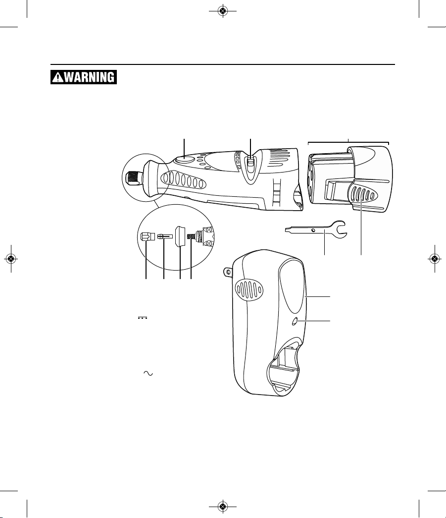
Functional Description and Specifications
Disconnect battery pack from tool or place the switch in the locked or off position
before making any assembly, adjustments or changing accessories. Such preventive
safety measures reduce the risk of starting the tool accidentally.
Model 7300-PGT Cordless Rotary Tool
Model number . . . . . .7300-PGT
Voltage rating . . . . . . .4.8V
Rated speed . . . . . . . .n 6,500-14,000/min
Collet capacities . . . . .1/32, 1/16", 3/32", 1/8"
Charger . . . . . . . . . .760-01
Charge Time . . . . . . . .3 Hour
Voltage rating . . . . . . .120 V 60 Hz
Battery pack . . . . . . . .755-01
Capacity . . . . . . . . . . .200 mA
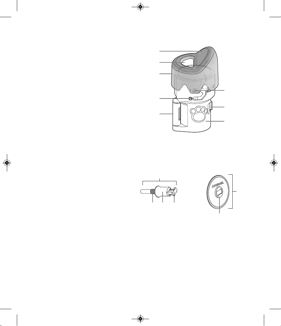
1
3
9
7
10
11
654
8
1 Shaft lock button
2 Switch
3 Battery pack
4 Collet nut
5 Collet
6 Nose cap
7 Shaft
8 Release tab
9 Collet wrench
10 Charger
11 Charger indicator
2610046266_7300-PGT 3/21/17 10:17 AM Page 12
13
AT01-PGA Pet grooming attachment
8
5
2
7
6
3
1
4
9
10 11 12
14
13
EZ402 EZ Lock™ Mandrel and SD60PGA Sanding disc
1 Attachment housing
2 Clear cap
3 Clasp
4 Hinge
5 Sanding disc opening
6 Tab (part of clear cap)
7 Depth guide
8 Ramp
9 EZ Lock™ mandrel EZ402
10 Blue spacer
11 Spring-loaded sleeve
12 Bow tie interface
13 Sanding disc SD60PGA
14 Bow tie interface
2610046266_7300-PGT 3/21/17 10:17 AM Page 13
14
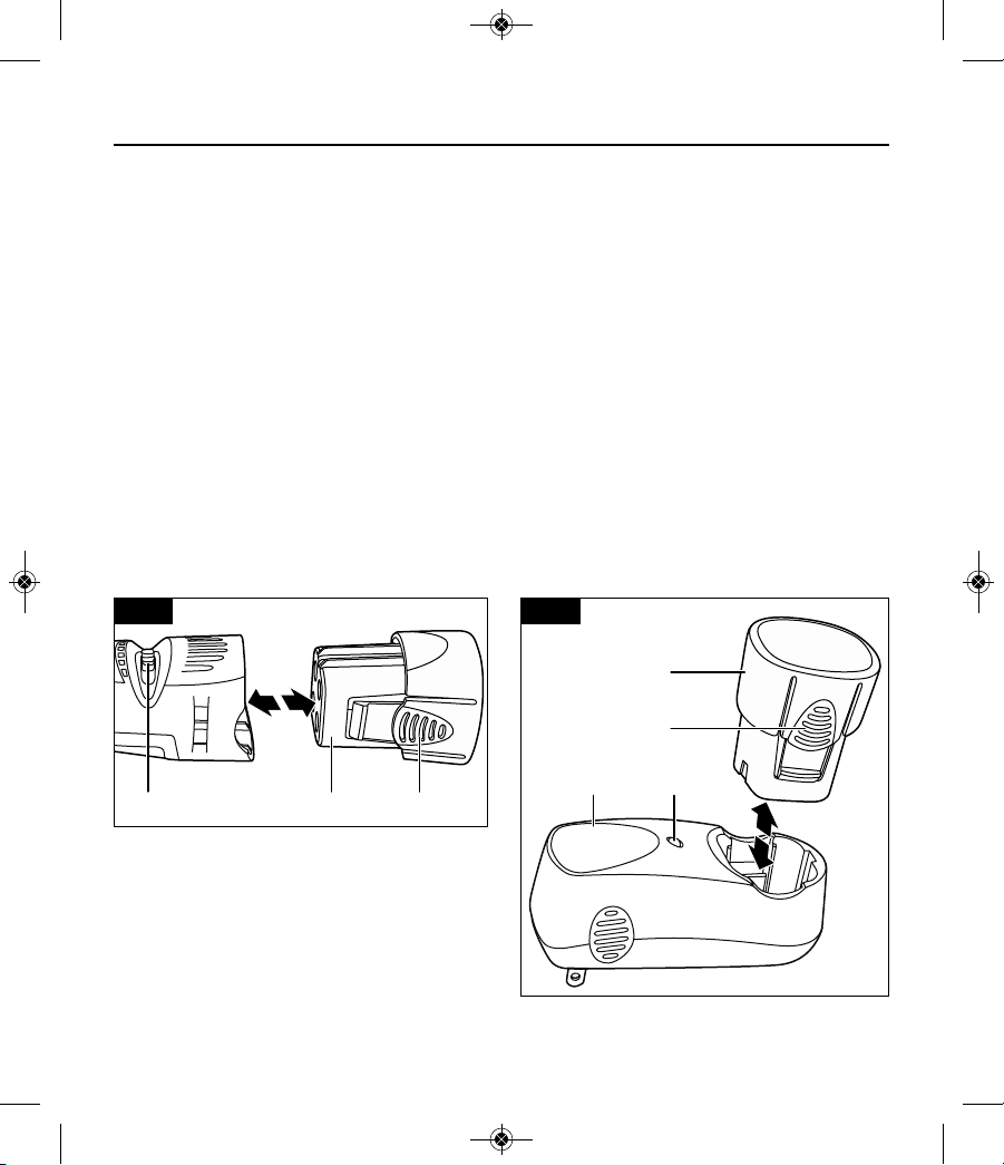
Charging battery Pack
- Charging the battery
The battery pack is not fully charged. Be sure to charge
pack prior to initial use. For best re sults on first charge,
charge pack overnight.
1. Make sure the switch 3 in the “OFF” (O) position.
Squeeze release tabs 2 on both sides of battery
pack 1, and remove pack from the tool (Fig. 1).
2. Align the battery pack 1 with the charger 4 as
shown, squeeze release tabs 2, insert battery pack
into charger and release pressure on tabs so it
locks in place (Fig. 2).
4. Plug charger into the power source. The charger
indicator light 5 will light up green, indicating that
connection has been made and the battery pack is
charging. The indicator light will blink while charging. The indicator light will turn solid when charging is complete (Fig. 2). Under normal tool usage
the battery requires 3 hours charging time to
reach full capacity.
5. When charging is completed, squeeze release tabs
2 on battery pack and remove pack 1 from charger
(Fig. 2).
6. Align the battery pack with the tool as shown.
Squeeze release tabs 2, insert battery pack 1 into
the tool, and release pressure on tabs 2 so it locks
in place (Fig. 1).
- Important Charging Notes
If you anticipate long periods of non-use for your tool
it's best to unplug your charger and battery pack from
its power source. Unplugging the charger will extend
the life expectancy of the charger and battery pack.
The battery pack accepts only about 80% of its maximum charge capacity with its first charge; or, after prolonged storage it will also require additional time on the
first charge. However, after several charge and discharge cycles, the batteries should be up to full charge
capacity and delivering maximum performance.
FIG. 1 FIG. 2
1
1
3 2
2
4 5
2610046266_7300-PGT 3/21/17 10:17 AM Page 14
Assembly Instructions for pet nail grooming
Disconnect battery pack from tool or place the switch in the locked or off position
before making any assembly, adjustments or changing accessories. Such preventive
safety measures reduce the risk of starting the tool accidentally.
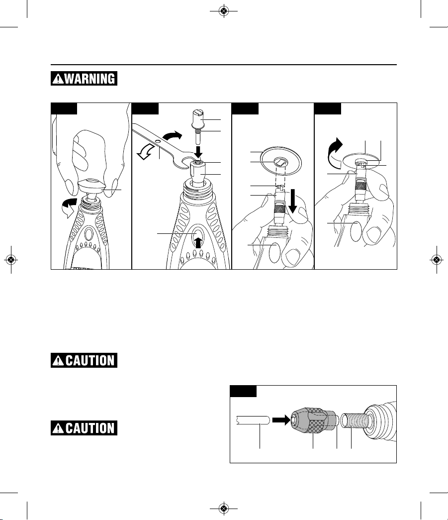
To load mandrel:
1. Unscrew and remove the nose cap 1 from the tool
by twisting it counter-clockwise until it comes off
the tool (Fig. 1).
2. To loosen the collet nut, first press shaft lock button 2 and rotate the collet nut 3 by hand until the
lock engages the shaft preventing further rotation
(Fig. 2).
Do not engage shaft lock
while the tool is running.
3. With the shaft lock 2 engaged, loosen the collet
nut 3 (turn counterclockwise L). Use the wrench 7
if necessary. The collet nut must be loosely
threaded on when inserting an accessory (Fig 2).
4. Insert EZ Lock™ mandrel 6 into collet 4 (Fig. 2).
Make sure the blue spacer 5
on the mandrel bottoms out
on the collet nut, setting the mandrel to the correct
depth. Failure to set the mandrel to the correct depth
can result in damage to the attachment.
5. With the shaft lock 2 engaged, tighten the collet nut
3 securely (turn clockwise T) with wrench 7 (Fig. 2).
Note: If the EZ Lock™ mandrel does not fit into the
collet, it is possible that the collet is stuck within the
collet nut. If this happens, remove the collet nut from
the tool by continuing to twist it counterclockwise. If
the collet does not separate from the collet nut when
removed from the tool, push the shank of the EZ
Lock™ mandrel 6 into the hole in the collet nut 3. This
should cause the collet 4 to pop out of the collet nut
3. Re-assemble by placing the collet 4 into the output
1
FIG. 1
L
T
90°
FIG. 2 FIG. 3 FIG. 4
7
6
12
11
10
12 11
10
9
2
9
2
5
4
3
2
15
6348
FIG. 5
2610046266_7300-PGT 3/21/17 10:17 AM Page 15
16
shaft 8 and twisting the collet nut 3 clockwise over the
collet to tighten it back onto the output shaft 8 (Fig. 5).
To load sanding disc:
1. Pull spring-loaded sleeve 9 DOWN towards tool
with one hand and hold. You can brace the tool on
the body or workbench for extra leverage (Fig. 3).
2. With the other hand, align bow tie interface 10 on
mandrel with metal bow tie interface 11 on bottom
of sanding disc 12 (Fig. 3).
3. Place sanding disc on the mandrel to a point just
below the bow tie on the mandrel 10 and twist 90
degrees until the bow tie interface 11 on the sanding disc 12aligns with the sleeve 9. Release sleeve
9. Sanding disc 12 should lock in place (Fig. 4).
Incorrect seating of sanding
disc on mandrel may lead to
personal injury or property damage. To check for
proper seating, hold shaft lock button 2 and twist the
sanding disc 12. The sanding disc 12 will not be able
to rotate on mandrel.
To unload sanding disc:
1. Pull spring-loaded sleeve 9 DOWN toward tool
with one hand (Fig. 4).
2. Hold sleeve 9 down while twisting sanding disc 12
90 degrees (Fig. 4).
3. Remove sanding disc 12 (Fig. 4).
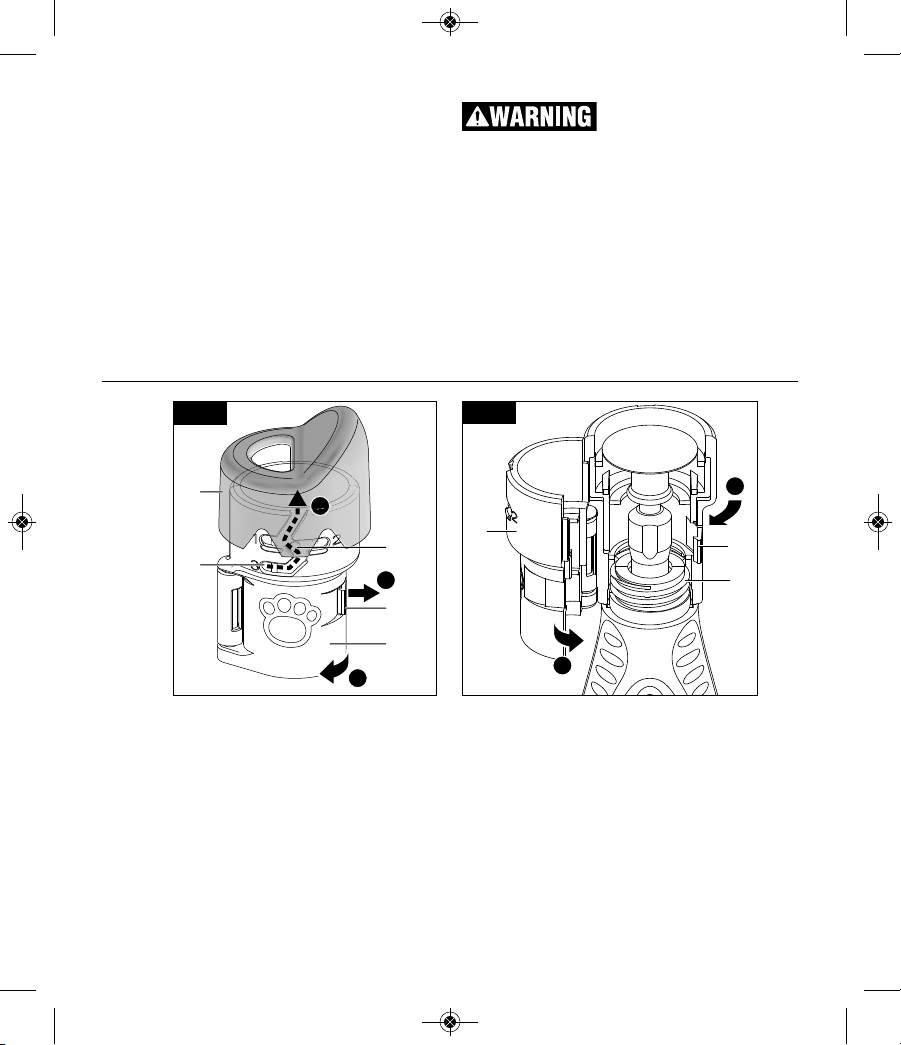
To attach nail guard attachment:
Note: Make sure that the mandrel and the sanding
disc are mounted properly before mounting the
attachment.
A. Detach the clear cap 2 from the attachment by
running the small knobs 6 on the inside of the
clear cap up along the height adjustment guide 7
until they reach the guided opening (Fig. 6).
B. Unlock the clasp 3.
C. Open the attachment 1 (Fig. 6).
D. Position the attachment 1 around the threaded
nose of the tool 8 and close the attachment
together until the clasp 3 is fully engaged (Fig. 7).
E. Turn the whole attachment 1 clockwise to screw it
into place on the threaded nose 8. Make sure that
it is securely tightened so that it will not shift positions during use (Fig. 7).
F. Re-attach the clear cap 2 (simply perform step A
in reverse order).
G. Turn the clear cap so that the small knobs are all
the way to the end of slot 7 (next to number “3”)
on the attachment. You will hear the cap click into
B
C
A
FIG. 6
D
E
FIG. 7
2
6
3
1
1
3
8
7
2610046266_7300-PGT 3/21/17 10:17 AM Page 16
17
Observe all warnings and
safety instructions when
using the rotary tool. Failure to follow recommended
procedures could result in personal injury or property
damage.
Why Use a Dremel Rotary Tool
to Groom Pet Nails?
Scissors and guillotine-type clippers apply pressure
and pinch the nail, which can be uncomfortable for
pet toes and feet. Clipping toenails also increases the
likelihood of cutting the internal blood supply to the
nail, called the quick; grinding is more gradual and
controlled. If the quick is nicked using a rotary tool,
the cut is usually smaller and will heal quicker than a
cut made with a nail clipper.
Before you start
Grooming a pet’s nails for the first time can be a worrisome experience for both the pet and pet owner.
Rest assured that nail grooming does not have to be
a stressful experience. By starting early and considering grooming to be part of your pet’s training, your
pet will grow used to the experience.
First, train your pet to feel comfortable with their
paws being touched and handled before exposing
them to the rotary tool. One way to do this is to massage their legs, paws, and individual toes for a few
minutes at least once a day. Afterwards, create a positive association with this experience by rewarding
your pet with its favorite snack.
Next, help your pet grow gradually accustomed to the
rotary tool. Let your pet sniff the tool while it is
turned off. Then, while keeping the tool in your hand,
let your pet listen to the sound the tool makes when it
is turned on. Ideally, have your pet sit or lay on its
side while the tool is in your hand and running.
Gradually work up to having your pet’s toenails touch
the rotating sanding disc for less than a second. Do
not grind the nails yet; simply let your pet become
familiar with the tool. Throughout the acclimation
process, continue to praise your pet and reward good
behavior with a snack. This process may take a couple of days or weeks. Before long, both you and your
pet will be able to relax and even enjoy the grooming
time that you share together.
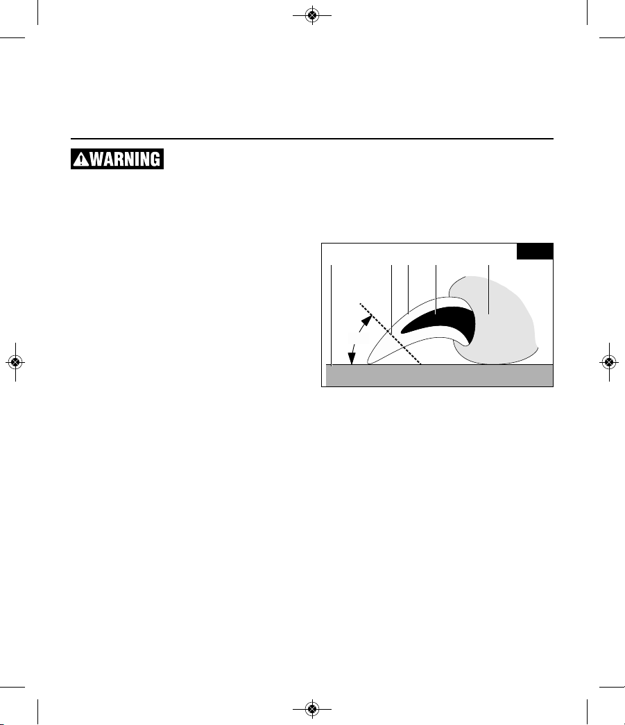
Nail Anatomy
The nails/claws containing quick vessels described in
this section are relevant to several types of pets,
including dogs and cats.
Before trimming your pet’s nails, you will need to
identify the quick. The diagram (Fig. 8) shows the
basic anatomy of a pet’s toenail. The outer nail is
hard and has no feeling because it has no nerve endings. The core of the nail is the quick. It is made up
of tiny blood vessels and nerve endings and is very
sensitive. The quick is a vein that “feeds” the toenail.
Should you cut the quick while trimming a nail, the
nail will start to bleed.
Light colored nails are often transparent enough to
allow you to see the quick’s pink core. Dark colored
nails may not allow you to see where the quick is located. Pets may have both light and dark colored nails
Nail Grooming Operating Instructions
45°
45123
FIG. 8
1 Nail / Claw
2 Quick
3 Paw
4 Floor
5 Trim line
place when fully installed. Do not force the clear
cap out of the guides (Fig. 6).
Note: Refer to the AT01-PGA manual on the Dremel
website for additional information regarding
attachment compatibility.
2610046266_7300-PGT 3/21/17 10:17 AM Page 17
that allow you to estimate the length of the quick.
The diagram also shows an estimate of the proper
angle at which to trim a pet’s nails. A rule of thumb
for the proper angle is 45 degrees upwards from the
bottom of the paw. The proper angle may vary
according to the pet owner’s wishes or the pet’s
unique anatomy. Trim nails so that they almost touch
the ground when your pet is walking.
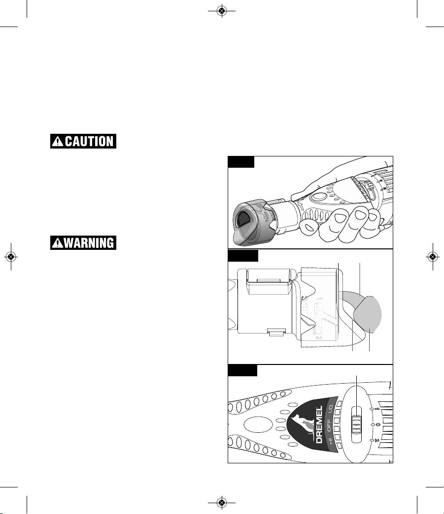
The Nail Grooming Process
Use only “golf grip” or “hand
grip” method of holding the
tool. Never hold the tool by the attachment. Holding
the tool by the attachment could cause it to unexpectedly shift, causing loss of control (Fig.9).
Place the pet’s paw 4 on the ramp 1 so that the nail 3
is close to - but not touching - the sanding disc 2
(Fig.10).
Turn the tool on by sliding the tool switch 5 to “LO”
(or “1”) position (Fig. 11), which corresponds to
approximately 6,500 RPM.
Maximum operating speed
for pet grooming applications
is 10,000/min. Use only "LO" (1) speed setting. Use
of higher operating speeds may cause heat buildup
and injury to the pet.
Note: Refer to the AT01-PGA manual on the Dremel
website for additional information regarding operating speeds for pet grooming.
Support the toe and nail in one hand while using the
rotary tool in the other hand. This is more comfortable for your pet as it lessens vibration on the paw.
Pushing gently on the bottom of the paw’s pad
extends the nail slightly for easier grooming.
It is important to let the speed of the rotary tool do the
work; never apply pressure to the toenail with the
spinning sanding disc. Pressure may cause the nail to
grow too hot, resulting in discomfort for your pet. The
rotary tool’s spinning sanding disc should not be kept
against the nail longer than three seconds at a time.
Instead of focusing on completing one nail at a time,
it is recommended to briefly trim each nail on one
paw, and then the other, in several passes. This
allows time for the nails to cool. You may repeat this
process as needed. Trim nails so that they almost
touch the ground when your pet is walking.
Turn the tool off by sliding the tool switch 5 to “OFF”
(or “0”) position (Fig. 11).
Pet Safety Tips
Some pets may become nervous in the presence of
the tool so it is best to secure your pet. The operator
will need both hands to groom the nails so it may be
helpful to have another person assist in restraining
your pet.
If hair is accidentally caught in the rotary tool, immediately turn off the tool and untangle the hair from the
tool. For pets with particularly long hair, use an old
32
14
FIG. 9
FIG. 10
5
FIG. 11
18
2610046266_7300-PGT 3/21/17 10:17 AM Page 18
19
Assembly Instructions for applications
other than pet nail grooming
7300-PGT can also be used with variety of Dremel
accessories that will turn this tool into a carver, a
grinder, polisher, sander, cutter, power brush, drill
and more.
First, reverse the assembly steps on pages 15 and 16
to remove pet grooming attachment, EZ Lock™ mandrel and reinstall the nose cap.
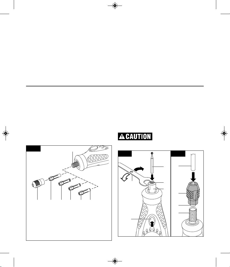
Collets
Dremel accessories such as engraver bits, grinding
stones and mandrels are mounted on the tool using
collet and collet nut system.
7300-PGT comes with the 1/8” collet No 480. There
are also three other collets to accomodate smaller
diameter accessories. Identification (ID) rings will
help you choose the right collet for your bits
(Fig. 12).
To loosen collet nut 3, first press shaft lock button 2
and rotate the collet nut counterclockwise (L) by hand
until the lock engages the shaft preventing further rotation (Fig. 13).
Do not engage lock while the
tool is running.
With the shaft lock engaged, loosen the collet nut by
L
T
FIG. 13
7
5
4
3
2
5
3
4
8
FIG. 14
4A 4B 4C 4D 93
8
FIG. 12
3 Collet nut
4A 1/8” collet #480 - no ID rings
4B 3/32” Collet 481 - three ID rings
4C 1/16” Collet 482 - two ID rings
4D 1/32” Collet 483 - one ID ring
9 ID ring
sock to cover the toe, foot, and leg of the pet and isolate the nail. Push the nail out through a small opening at the tip of the sock to groom the nail. Keep styptic powder on hand in case of bleeding. Styptic powder is available at most pet supply stores. Follow the
directions on the packaging for proper use instructions.
Cleaning the Pet Grooming Attachment
Remove the pet grooming attachment from the rotary
tool as needed to clean out any nail dust or debris.
Wash only the attachment with warm water and dry
thoroughly with a clean cloth before reinstalling on
rotary tool.
2610046266_7300-PGT 3/21/17 10:17 AM Page 19

20
hand (use the collet wrench 7 if necessary). Change
accessories 5 by inserting the new one into the collet 4
as far as possible to minimize runout and unbalance
(Fig. 13).
With the shaft lock engaged, finger tighten the collet
nut 3 in counterclockwise (T) direction until the accessory shank 5 is gripped by the collet (Fig. 13). Avoid
excessive tightening of the collet nut when there is
no bit inserted.
To install a different collet, completely unscrew the collet nut 3 and remove the old collet 4. Insert the unslotted end of the collet in the hole in the end of the tool
shaft 8. Replace collet nut on the shaft (Fig. 13).
Always use the collet, which matches the shank size
of the accessory you plan to use. Never force a larger
diameter shank into a collet.
- Fixing stuck collets
It is possible for a collet to get stuck within the collet nut
especially if a collet nut is tightened onto the tool without a
bit in place. If this happens, the collet 4 can be removed
from the collet 3nut by pushing the shank of an accessory
6 into the hole in the collet nut. This should cause the collet to pop out of the collet nut (Fig. 14).
- Balancing accessories
For precision work, it is important that all accessories
be in good balance (much the same as the tires on your
automobile). To true up or balance an accessory,
slightly loosen collet nut and give the accessory or collet a 1/4 turn. Re tighten collet nut and run the Cordless
Rotary Tool. You should be able to tell by the sound
and feel if your accessory is running in balance.
Continue adjusting in this fashion until best balance is
achieved. To maintain balance on abrasive wheel
points, before each use, with the wheel point secured
in the collet, turn on the Cordless Rotary Tool and run
the 415 Dressing Stone (not included, available as
accessory) lightly against the revolving wheel point.
This removes high spots and trues up the wheel point
for good balance.
Remember, your new Dremel Cordless Rotary Tool is
the finest power tool of its kind. But its performance
is only as good as the accessories with which it is
used. We recommend only Dremel accessories be
used. Use of any other accessories may create a hazard. We hope you’ll enjoy many years of trouble free
pleasure from your Dremel Cordless Rotary Tool.
Operating Instructions for applications
other than pet nail grooming
Observe all warnings and
safety instructions when
using the rotary tool. Failure to follow recommended
procedures could result in personal injury or property
damage.
Introduction
Your Cordless Rotary Tool has a small, powerful elec tric motor, is comfort able in the hand, and is made to
accept a large variety of accessories including abrasive wheels, drill bits, wire brushes, polishers,
engraving cutters, and cutting wheels. Accessories
come in a variety of shapes and permit you to do a
num ber of different jobs. As you be come familiar with
the range of accessories and their uses, you will learn
just how versatile your Cordless Rotary Tool is. You’ll
see dozens of uses you hadn’t thought of before now.
The real secret of the Cordless Rotary Tool is its
speed. To understand the advantages of its high
speed, you have to know that the standard portable
electric drill runs at speeds up to 2,800 revolutions
per minute. The typical electric drill is a low-speed,
high torque tool; the Cordless Rotary Tool is just the
opposite — a high-speed, low torque tool. The chief
difference to the user is that in the high speed tools,
the speed combined with the acces sory mounted in
the collet does the work. You don’t apply pressure to
the tool, but simply hold and guide it. In the low speed
tools, you not only guide the tool, but also apply pres sure to it, as you do, for example, when drilling a hole.
It is this high speed, along with its compact size and
wide variety of special accessories, that makes your
Cordless Rotary Tool differ ent from other power
tools. The speed enables it to do jobs low speed tools
cannot do, such as en graving glass, etc.
2610046266_7300-PGT 3/21/17 10:17 AM Page 20
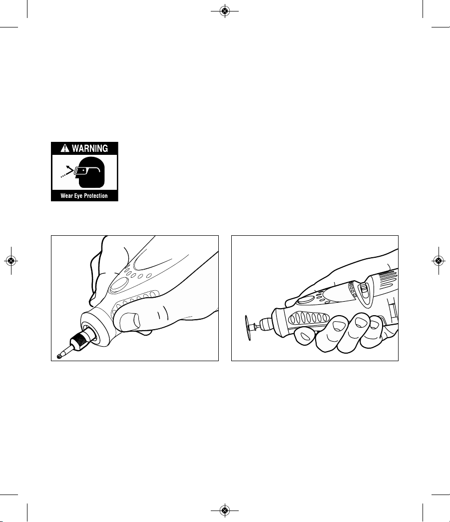
21
For best control in close work, grip the Rotary Tool
like a pencil between your thumb and forefinger.
The “handgrip” method of holding the tool is used for
operations such as grinding a flat surface or using
cutoff wheels.
Getting the most out of your Cordless Rotary Tool is
a matter of learning how to let this speed work for
you.
Using the Cordless Rotary Tool
The first step in learning to use the Cordless Rotary Tool
is to get the “feel” of it. Hold it in your hand and feel its
weight and balance. Feel the taper of the housing. This
taper permits the tool to be grasped much like a pen or
pencil.
When you turn on the tool for
the first time, hold it away from
your face. Accessories can be
damaged during handling, and
can fly apart as they come up to
speed. This is not common, but
it does happen.
Practice on scrap materials first to see how the Cordless
Rotary Tool cuts. Keep in mind that the work is done by
the speed of the tool and by the accessory in the collet.
You should not lean on or push the tool into the work.
Instead, lower the spinning accessory lightly to the
work and allow it to touch the point at which you want
cutting (or sanding or etching, etc.) to begin. Con centrate on guiding the tool over the work using very little pressure from your hand. Allow the accessory to do
the work.
Usually, it is best to make a series of passes with the
tool rather than attempt to do all the work in one pass.
To make a cut, for example, pass the tool back and forth
over the work, much as you would a small paint brush.
Cut a little material on each pass until you reach the
desired depth. For most work, the deft, gentle touch is
best. With it, you have the best control, are less likely to
make errors, and will get the most effi cient work out of
the accessory.
2610046266_7300-PGT 3/21/17 10:17 AM Page 21
22
Operating Speeds for applications
other than pet nail grooming
Set the speed indicator to fit the job to achieve the
best job results when working with different materials.
To select the right speed for each job, use a practice
piece of material. Vary speed to find the best speed
for the accessory you are using and the job to be
done.
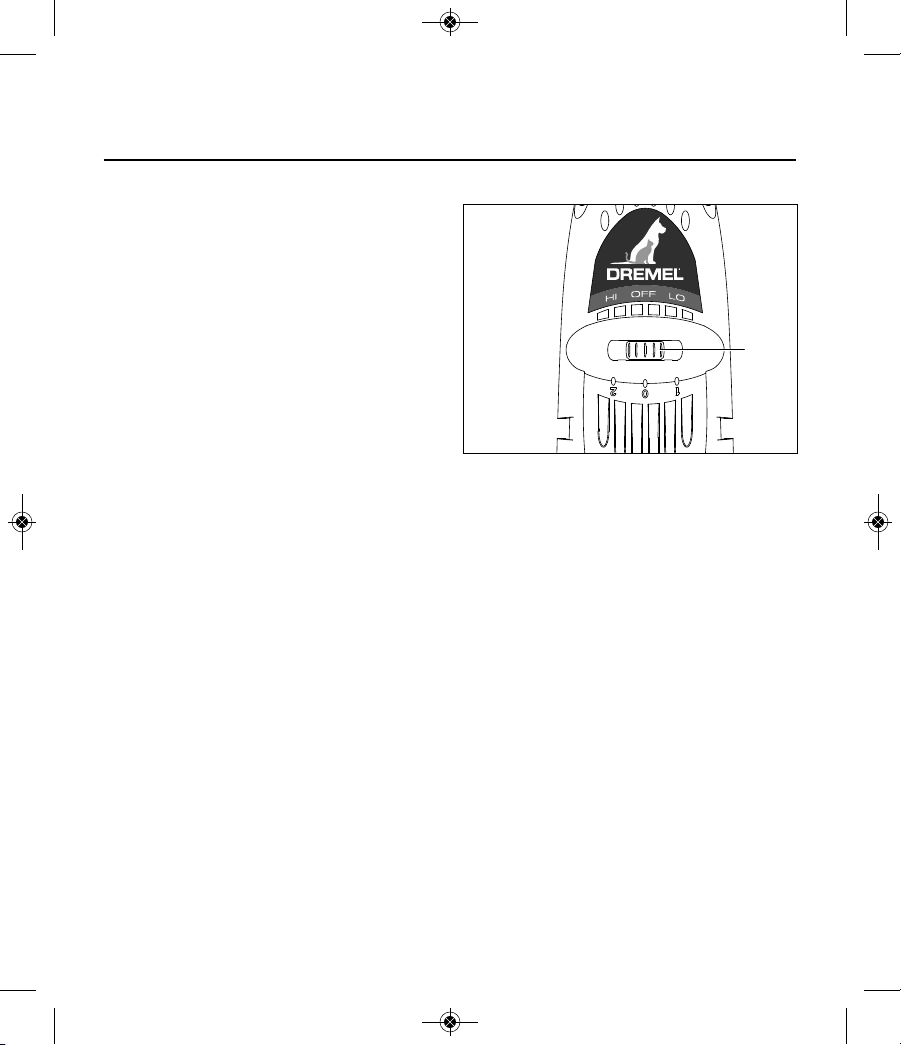
On the Model 7300-PGT, there is a LO and HI switch
10. When the switch indicator is in position 1 or LO, the
tool runs at about 6,500 RPM. When the switch indicator is in position 2 or HI, the tool runs at about 14,000
RPM.
You can refer to the charts on pages 23 and 24 to
determine the proper speed, based on the materi al
being worked and the type of cutter or other accessory
being used. These charts enable you to select both the
correct acces sory and the optimum speed at a glance.
Needs for Slower Speeds
Certain materials, however, (some plastics, for ex ample) require a relatively slow speed because at high
speed the friction of the tool generates heat and causes the plastic to melt.
10
2610046266_7300-PGT 3/21/17 10:17 AM Page 22
23
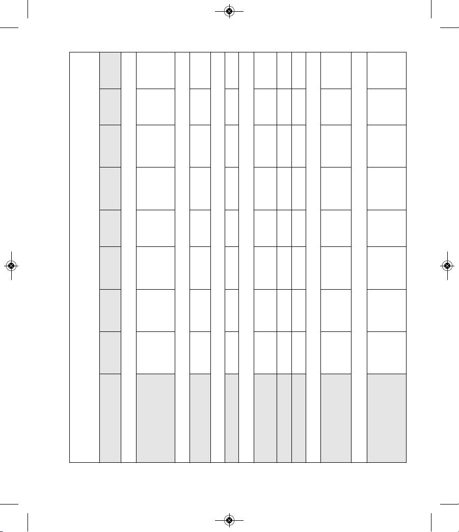
SPEED SETTINGS
Speed for plastic depends on thickness of material or amount of material to be removed.
CATALOG NUMBER
SOFT
WOOD
HARD
WOOD
LAMINATES
PLASTIC
STEEL
ALUMINUM,
BRASS, ETC.
SHELL/
STONE
CERAMIC GLASS
HIGH SPEED CUTTERS
100, 114, 115, 116, 117,
118, 121, 124, 125, 134,
144, 190, 191, 192, 193,
194, 196, 198, 199
2 2 1
2
SMALL ENGRAVING CUTTERS
105, 106, 107, 108, 109,
110, 111, 112, 113
2 2 1 2 2
RUBBER POLISHING POINT
425 2
CUTTING ACCESSORIES
409, 420, 426, 540,
EZ456, EZ409,EZ476
1 2 2 2
2
543, EZ544 2 2
1
2 2
545, EZ545 2 2
DIAMOND WHEEL POINTS
7103, 7105, 7117,
7120, 7122, 7123,
7134, 7144
2 2
2
2
ALUMINUM OXIDE GRINDING STONES
541, 903, 911, 921, 932,
941, 945, 952, 953, 954,
971, 997, 8153, 8175,
8193, 8215
2 2 2 1 2 2
2610046266_7300-PGT 3/21/17 10:17 AM Page 23
24
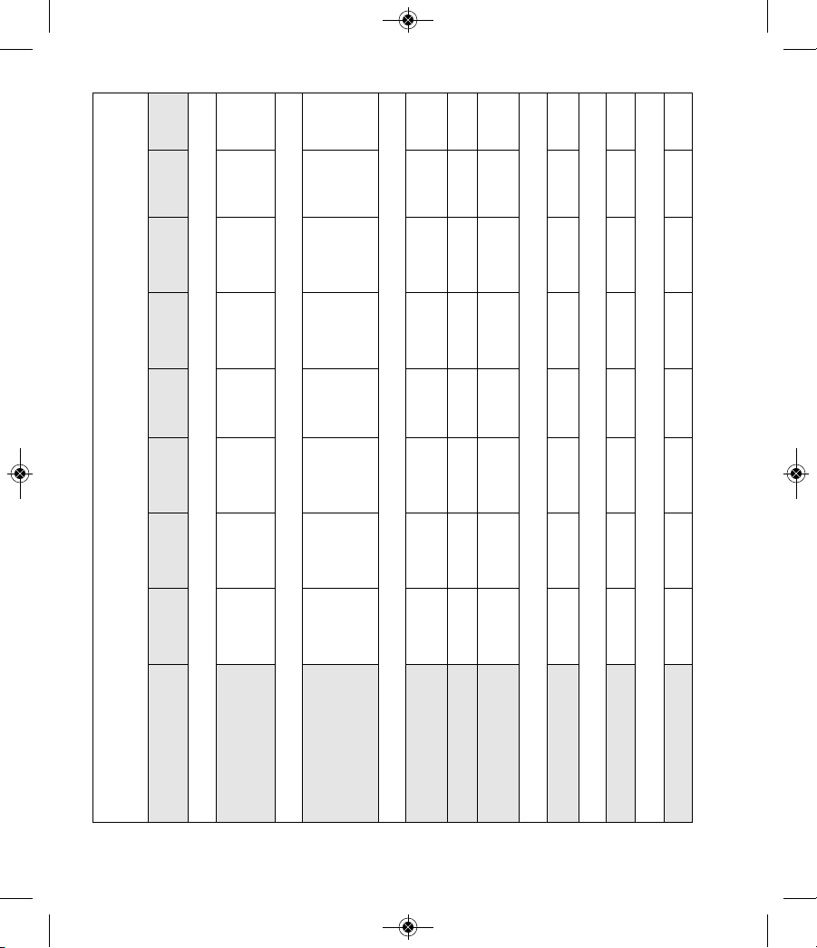
SPEED SETTINGS
Speed for plastic depends on thickness of material or amount of material to be removed.
CATALOG NUMBER
SOFT
WOOD
HARD
WOOD
LAMINATES
PLASTIC
STEEL
ALUMINUM,
BRASS, ETC.
SHELL/
STONE
CERAMIC GLASS
SILICON CARBIDE GRINDING STONES
83142, 83322, 83702,
84922, 85422, 85602,
85622
2 2 1 2 2 2
TUNGSTEN CARBIDE AND STRUCTURED TOOTH TUNGSTEN CARBIDE CUTTERS
9901, 9902, 9903, 9904,
9905, 9906, 9912 9909,
9910, 9911 9931, 9932,
9933, 9934, 9935, 9936
2 2
1 2
SANDING BANDS AND DISCS
407, 408, 430, 431, 432,
438, 445, 446
1-2 1-2 1-2 2 2 1-2 1-2
411, 412, 413 2
2 1 1
EZ471SA, EZ472SA,
EZ473SA
1-2 1-2
1-2 2 2 1-2
1-2
FLAPWHEELS
502, 503, 504, 505 2
2 1 2 2
FINISHING ABRASIVE BUFFS
511E, 512E 2 2 1
2
2
DRILL BIT
150 2
2 1 2
2610046266_7300-PGT 3/21/17 10:18 AM Page 24
25
Service
NO USER SERVICEABLE
PARTS INSIDE. Preventive
maintenance performed by un au thorized personnel
may result in misplacing of internal wires and components which could cause serious hazard. We recom -
mend that all tool service be performed by a Dremel
Service Facility. SERVICE MEN: Disconnect tool and/or
charger from power source before servicing.
D.C. motors
The motor in your tool has been engineered for many
hours of dependable service. To maintain peak efficiency of the motor, we recommend it be examined every
six months. Only a genuine Dremel replacement motor
specially designed for your tool should be used.
Cleaning
To avoid accidents, always
disconnect the tool and/or
charger from the power supply before cleaning. The
tool may be cleaned most effectively with com pressed
dry air. Always wear safety goggles when cleaning
tools with compressed air.
Certain cleaning agents and
solvents damage plastic parts.
Some of these are: gasoline, carbon tetrachloride, chlorinated cleaning solvents, ammonia and household
detergents that contain ammonia.
Extension Cords
If an extension cord is neces-
sary, a cord with adequate size
conductors that is capable of carrying the current necessary for your tool must be used. This will prevent
excessive voltage drop, loss of power or overheating.
Grounded tools must use 3-wire extension cords that
have 3-prong plugs and receptacles.
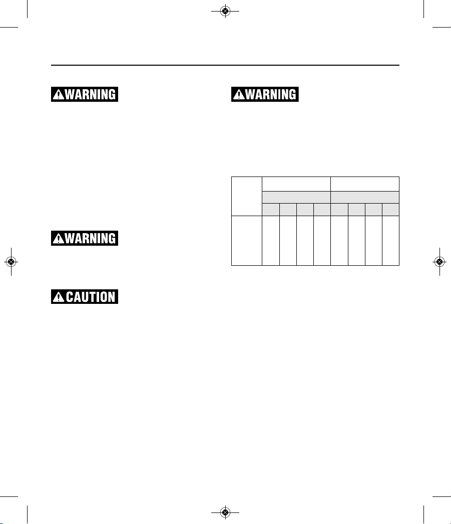
RECOMMENDED SIZES OF EXTENSION CORDS
120 VOLT ALTERNATING CURRENT TOOLS
NOTE: The smaller the gauge number, the higher the
cord capacity.
Maintenance
Tool’s
Ampere
Rating
Cord Size in A.W.G. Wire Sizes in mm
2
Cord Length in Feet Cord Length in Meters
25 50 100 150 15 30 60 120
3-6
6-8
8-10
10-12
12-16
18
18
18
16
14
16
16
16
16
12
16
14
14
14
–
14
12
12
12
–
0.75
0.75
0.75
1.0
–
0.75
1.0
1.0
2.5
–
1.5
2.5
2.5
4.0
–
2.5
4.0
4.0
–
–
2610046266_7300-PGT 3/21/17 10:18 AM Page 25
26
Dremel Accessories
Use only Dremel®, high-performance accessories. Other accessories are not designed
for this tool and may lead to personal injury or property damage.
Store accessories in a dry and temperate environment to avoid corrosion and deterioration.
The number and variety of accessories for the Rotary Tool are almost limitless. There is a category suited to
almost any job you might have to do and a variety of sizes and shapes within each category which en ables you
to get the perfect accessory for every need.
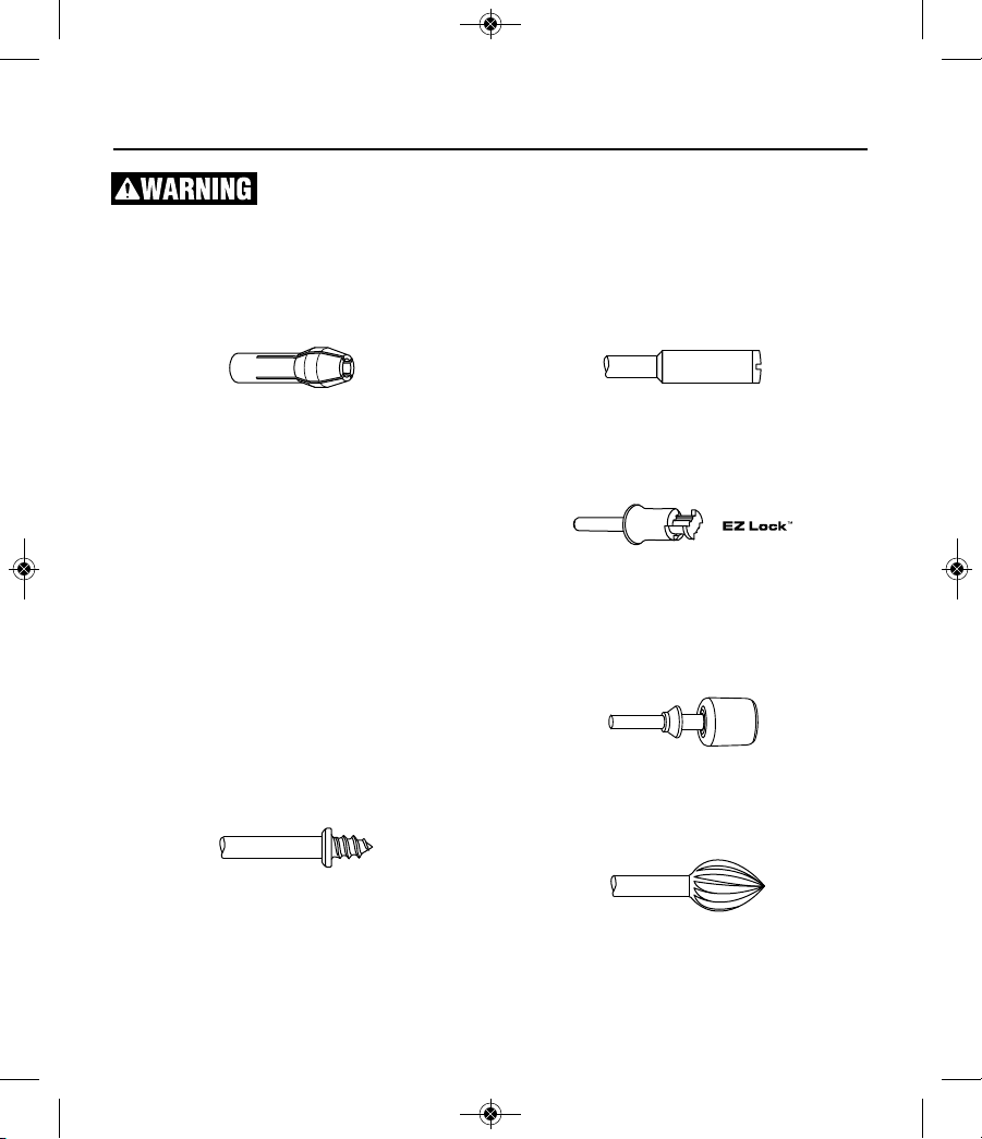
COLLETS
If you expect to use a variety of accessories, we recommend that in the beginning you purchase a complete set of four collets. Store these so that you will
have the proper size of collet for any accessory or drill
bit you want to use. Currently, the 1/8", 3/32",1/32"
and 1/16" collets accommodate all of the avail able
Dremel accessories. 1/8" collets are included in
most rotary tool kits.
MANDRELS
A mandrel is a shank with a threaded or screw head,
which are required when you use polishing accessories, cutting wheels, sanding discs, and pol ish ing
points. The reason mandrels are used is that sanding
discs, cutting wheels and similar accesso ries must be
replaced frequently. The mandrel is a per manent
shank, allowing you to replace only the worn head
when necessary, thus saving the expense of replacing
the shaft each time.
Screw Mandrel No 401
This is a screw mandrel used with the felt polishing
tip and felt polishing wheels. 1/8" shank.
Small Screw Mandrel No 402
This is a mandrel with a small screw at its tip, and is
used with emery and fiberglass cutting wheels, sanding discs and polishing wheels. 1/8" shank.
EZ Lock Mandrel No 402
The Dremel EZ Lock makes accessory changes easy
as PULL - TWIST - RELEASE. The one-piece mandrel
design simplifies the process of changing cutting
wheels, buffs and detail abrasive brushes (EZ Lock
compatible accessories).
EZ Drum™ Mandrel No EZ407SA
The Dremel EZ Drum makes accessory changes easy
as PULL - INSERT - PRESS DOWN. The one-piece
mandrel design simplifies the process of changing
sanding bands.
High Speed Cutters
Available in many shapes, high speed cutters are used
in carving, cutting and slotting in wood, plastics and
2610046266_7300-PGT 3/21/17 10:18 AM Page 26
27
soft metals such as aluminum, copper and brass.
These are the accessories to use for freehand routing
or carving in wood or plastic, and for precision cutting. Made of high quality steel. 1/8" shank.
Tungsten Carbide Cutters
These are tough, long-lived cutters for use on hard ened steel, fired ceramics and other very hard ma terials. They can be used for engraving on tools and
garden equipment. 1/8" shanks.
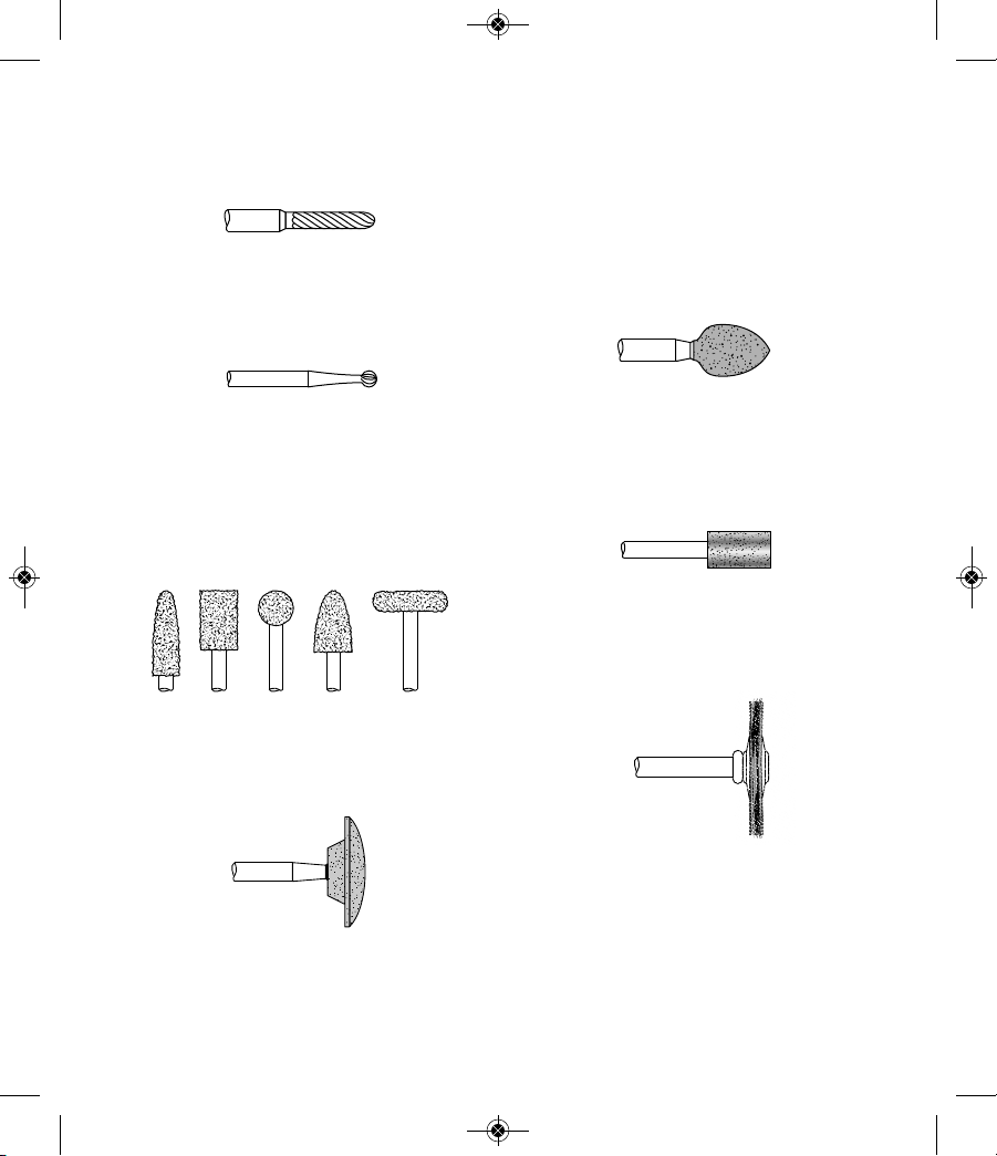
Engraving Cutters
This group has a wide variety of sizes and shapes,
and are made for intricate work on ceramics (greenware), wood carvings, jewelry and scrimshaw. They
often are used in making complicat ed printed circuit
boards. They should not be used on steel and other
very hard materials but are excellent on wood, plastic
and soft metals. 1/8" shank.
Structured Tooth
Tungsten Carbide Cutters
Fast cutting, needle-sharp teeth for greater material
removal with minimum loading. Use on fiberglass,
wood, plastic, epoxy and rubber. 1/8" shank.
Aluminum Oxide Grinding Stones (red/brown)
Round, pointed, flat — you name the shape and there
is one available in this category. These are made of
aluminum oxide and cover virtually every possible
kind of grinding application. Use them for sharpening
lawn mower blades, screwdriver tips, knives, scissors,
chisels and other cutting tools. Use to remove flash
from metal castings, deburring any metal after cutting,
smoothing welded joints, grinding off rivets and re mov ing rust. These grinding stones can be resharped
with a dressing stone. In machine shops, high speed
drills and cut ters normally are ground with aluminum
oxide wheels. 1/8" shank.
Silicon Carbide Grinding Stones (blue/green)
Tougher than aluminum oxide points, these are made
es pecially for use on hard materials such as glass and
ce ramics. Typical uses might be the removal of stilt
marks and excess glaze on ceramics and engraving
on glass. 1/8" shank.
Diamond Wheel Points
Excellent for fine detail work on wood, jade, ceramic,
glass and other hard material. Bits are covered with
diamond particles. 1/8" shanks. (Not recommended
for drilling)
Wire Brushes
Three different shapes of wire brushes are available.
For best results wire brushes should be used at
speeds not greater than 15,000 RPM. Refer to
Operating Speeds section for proper tool speed setting. The three shapes come in three different materi-
als: stainless steel, brass and carbon wire. The stainless steel perform well on pewter, aluminum, stain-
2610046266_7300-PGT 3/21/17 10:18 AM Page 27
28
less steel, and other metals, without leaving "afterrust". Brass brushes are non sparking, and softer than
steel; making them good for use on soft metal like
gold, cooper and brass. The carbon wire brushes are
good for general purpose cleaning.
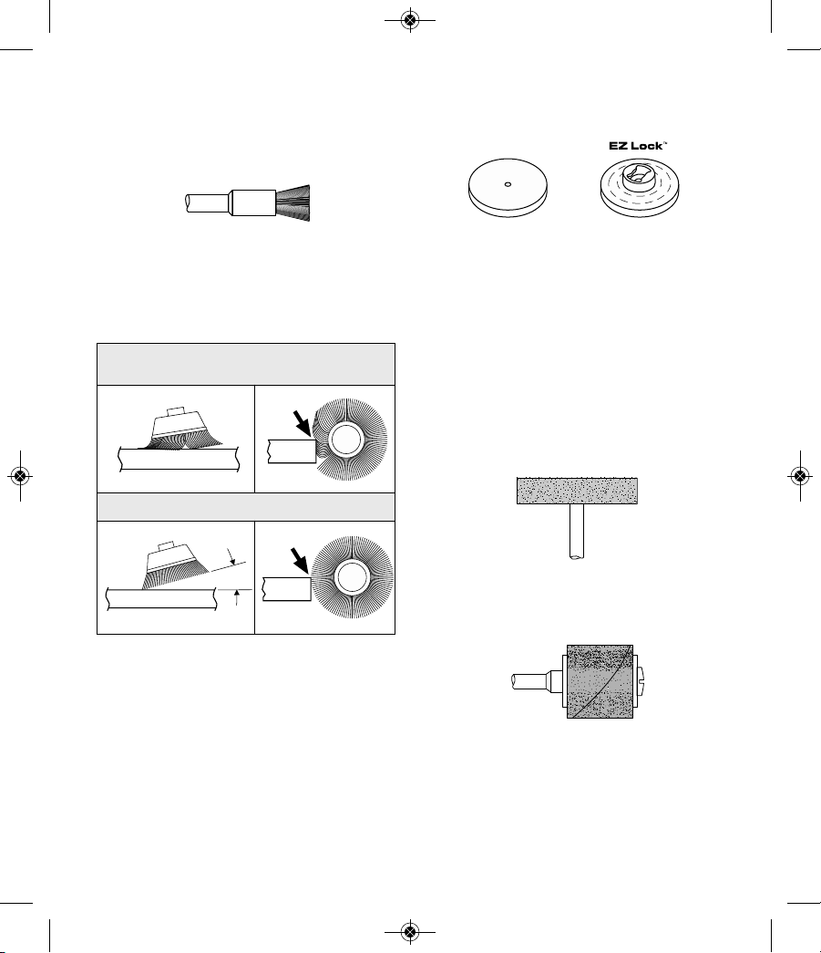
Bristle Brushes
These are excellent cleaning tools on silverware, jew elry and antiques. The three shapes make it possible
to get into tight corners and other difficult places.
Bristle brushes can be used with polishing compound
for faster cleaning or polishing.
Brushing Pressure
1. Remember, the tips of a wire brush do the work.
Operate the brush with the lightest pressure so
only the tips of the wire come in contact with the
work.
2. If heavier pressures are used, the wires will be
overstressed, resulting in a wiping action; and if
this is continued, the life of the brush will be shortened due to wire fatigue.
3. Apply the brush to the work in such a way that as
much of the brush face as possible is in full contact
with the work. Applying the side or edge of the
brush to the work will result in wire breakage and
shortened brush life.
Polishing Accessories
These include an impregnated polishing point and an
impregnated polishing wheel for bringing metal sur faces to smooth finish; a felt polishing tip and felt
polish ing wheel, and cloth polishing wheel, all used
for polishing plastics, metals, jewelry and small parts.
Also included in this group is a polishing compound
(No. 421) for use with the felt and cloth polishers.
Polishing points make a very smooth surface, but a
high luster is obtained using felt or cloth wheels and
polishing compound. For best results polishing
accessories should be used at speeds not greater
than 15,000 RPM.
No polishing compound is needed when using the
425 Polishing Wheel.
Aluminum Oxide Abrasive Wheels
Use to remove paint, deburr metal, polish stainless
steel and other metals. Available in medium grit. 1/8"
shank.
Sanding Accessories
Sanding discs in fine, medium and coarse grades are
made to fit mandrel No. 402 and EZ407. They can be
used for nearly any small sanding job you might have,
from model making to fine furniture finish ing. In addition, there is the drum sander, a tiny drum which fits
into the Rotary Tool and makes it possible to shape
INCORRECT:
Excessive pressure can cause wire breakage.
CORRECT: Wire tips doing the work.
15°
2610046266_7300-PGT 3/21/17 10:18 AM Page 28
29
wood, smooth fiberglass, sand inside curves and
other diffi cult places, and other sanding jobs. You
replace the sanding bands on the drum as they
become worn and lose their grit. Bands come in fine
medium and coarse grades. Flapwheels grind and
polish flat or contoured surfaces. They are used most
effectively as a finishing sander after heavier surface
sanding and material removal is completed.
Flapwheels come in fine and coarse grades. Buffs are
a great finishing accessory for cleaning and light
sanding. They work effectively on metal, glass, wood,
aluminum and plastics. Coarse and medium buffs are
sold together. All buffs are sold individually. Do not
exceed 15,000 RPM in speed. 1/8" shank.
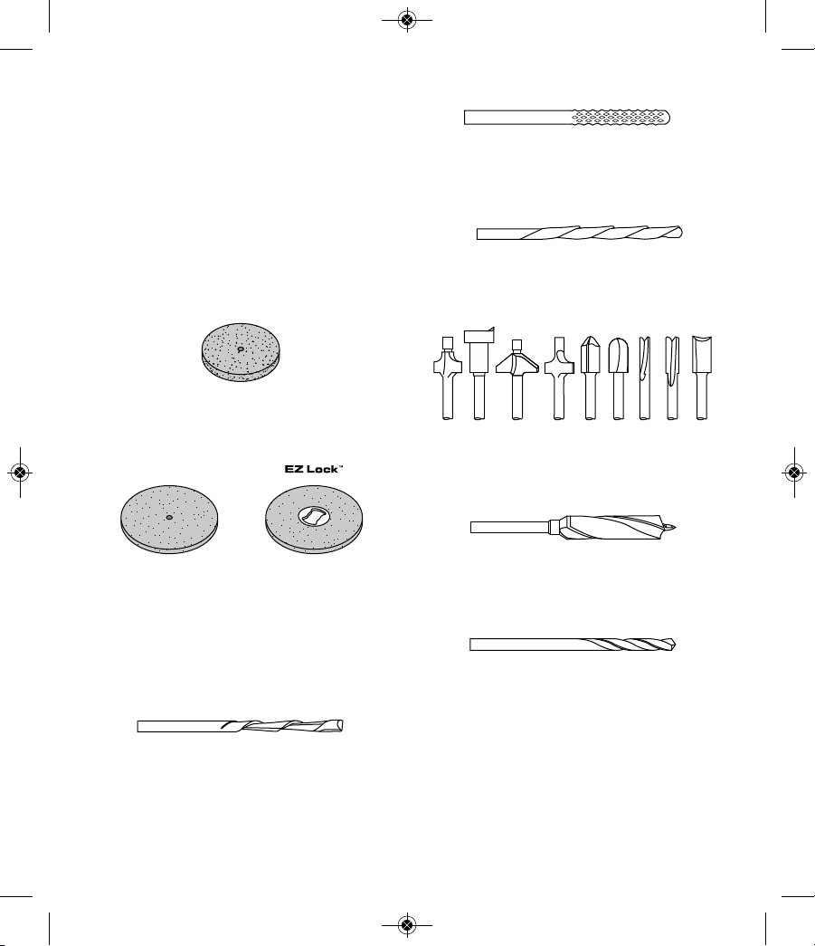
Grinding Wheel
Use for deburring, removing rust, and general purpose
grinding. Use with Mandrel #402.
Cutting Wheels
These thin discs of emery or fiberglass are used for
slicing, cutting off and similar operations. Use them
for cutting off frozen bolt heads and nuts, or to reslot
a screw head which has become so damaged that the
screwdriver won’t work in it. Fine for cutting BX cable,
small rods, tubing, cable and cutting rectangular
holes in sheet metal.
Drywall Cutting Bit
Gives you fast, clean cuts in drywall. Use with Dremel
No 565/566 Cutting Guide attachment.
Tile Cutting Bit
Cuts ceramic wall tile, cement board, and plaster.
Use with Dremel No 565/566 Cutting Guide attachment.
Spiral Cutting Bit
Cuts through all types of wood and wood composites.
Use with Dremel No 565/566 Cutting Guide attachment.
High Speed Router Bits
For routing, inlaying, and mortising in wood and other
soft materials. Use with Dremel No. 335 Router
attachment and No. 231 Shaper/Router table.
Brad Point Drill Bits
Titanium coated brad points stay on center and begin
drilling immediately. For use on wood. Size 1/8”,
5/32”, 3/16”, 1/4”. 1/8” shank.
HSS Drill Bits
HSS drill bit for use in metal and plastic. Size 1/8”,
7/64”, 3/32”, 5/64”, 1/16”, 3/64”, 1/32”. Shank size
matches the drill bit size. Different collet size (481,
482, 483) or Dremel chuck (4486) required according
to drill bit being used.
2610046266_7300-PGT 3/21/17 10:18 AM Page 29
30
Glass Drill Bits
Diamond tipped drill bits for use on glass and ceramic
wall tile. Lubricant included.
Collet Fan
Blows dust away for greater visibility to work piece.
Great for sanding, engraving and carving. Do not use
dust blower to stop or slow down the tool. Do not
contact dust blower with fingers or workpiece during
use.
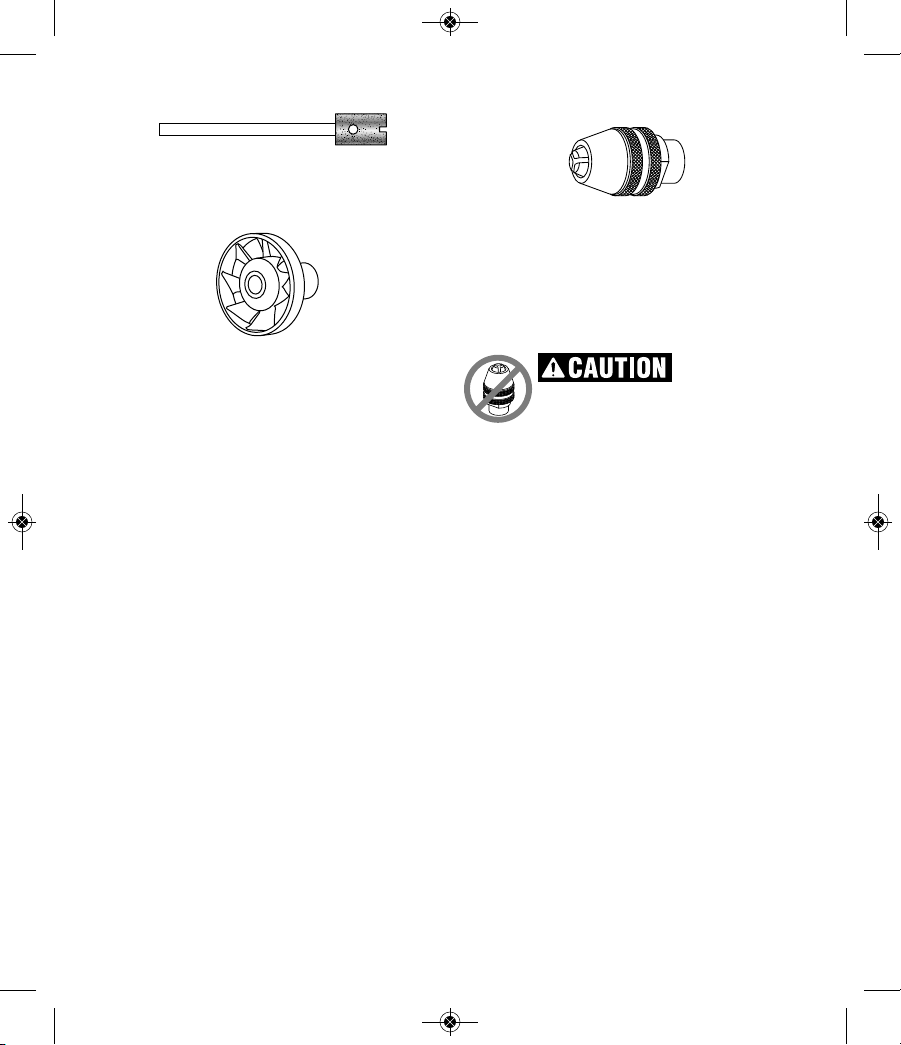
Dremel Chuck
This chuck allows you to quickly and easily change
accessories on Dremel Rotary Tools without changing collets. Accepts accessories with 1/32” - 1/8”
shank. Read instruction manual. Insert and securely
tighten the shank of the accessory well within the
jaws of the chuck.
Do not use Dremel
chuck with
AT01-PGA pet grooming attachment. Use
only 1/8” collet and collet nut. Use of the
Dremel chuck may result in damage to the
attachment.
2610046266_7300-PGT 3/21/17 10:18 AM Page 30
 Loading...