

Page 1
Page 2

Information in this document is subject to change without notice. Reproduction in any manner whatsoever, without the
written permission of D-Link Corporation, is strictly forbidden.
Trademarks used in this text: D-Link and the D-LINK logo are trademarks of D-Link Corporation; Microsoft and
Windows are registered trademarks of Microsoft Corporation.
Other trademarks and trade names may be used in this document to refer to either the entities claiming the marks
and names or their products. D-Link Corporation disclaims any proprietary interest in trademarks and trade names
other than its own.
© 2014 D-Link Corporation. All rights reserved.
December, 2013 P/N 651GS1510015G
FCC Warning
This equipment has been tested and found to comply with the limits for a Class A digital device, pursuant
to Part 15 of the FCC Rules. These limits are designed to provide reasonable protection against harmful
interference when the equipment is operated in a commercial environment. This equipment generates,
uses, and can radiate radio frequency energy and, if not installed and used in accordance with this
manual, may cause harmful interference to radio communications. Operation of this equipment in a
residential area is likely to cause harmful interference in which case the user will be required to correct
the interference at his expense.
CE Mark Warning
This is a Class A product. In a domestic environment, this product may cause radio interference in which
case the user may be required to take adequate measures.
Warnung!
Dies ist ein Produkt der Klasse A. Im Wohnbereich kann dieses Produkt Funkstoerungen verursachen. In
diesem Fall kann vom Benutzer verlangt werden, angemessene Massnahmen zu ergreifen.
Precaución!
Este es un producto de Clase A. En un entorno doméstico, puede causar interferencias de radio, en cuyo
case, puede requerirse al usuario para que adopte las medidas adecuadas.
Attention!
Ceci est un produit de classe A. Dans un environnement domestique, ce produit pourrait causer des
interférences radio, auquel cas l`utilisateur devrait prendre les mesures adéquates.
Attenzione!
Il presente prodotto appartiene alla classe A. Se utilizzato in ambiente domestico il prodotto può causare
interferenze radio, nel cui caso è possibile che l`utente debba assumere provvedimenti adeguati.
VCCI Warning
この装置は、クラス A 情報技術装置です。この装置を家庭環境で使用すると電波妨害を引き起こすこと
があります。この場合には使用者が適切な対策を講ずるよう要求されることがあります。 VCCI-A
BSMI Notice
此為甲類的資訊技術設備,在居住環境中使用時,可能會造成射頻擾動,在這種情況下,使用者會被要求
採取某些適當的對策。
Page 3

DGS-1510 Series Gigabit E thernet SmartPro Switch Hardware Installation Guide
Table of Contents
Table of Contents ................................................................................................................................................................. iii
Intended Readers .............................................................................................................................................................. v
Typographical Conventions ............................................................................................................................................... v
Notes, Notices, and Cautions ............................................................................................................................................ v
Safety Instructions ............................................................................................................................................................ vi
Safety Precautions ....................................................................................................................................................... vi
General Precautions for Rack-Mountable Prod uc ts ......................................................................................................... vii
Protecting Against Electrostatic Discharge ...................................................................................................................... viii
1. Introduction ................................................................................................................................................................. 9
Switch Description ............................................................................................................................................................. 9
Package Contents .............................................................................................................................................................. 9
Features ........................................................................................................................................................................... 10
Front-Panel Components ................................................................................................................................................. 11
Ports ............................................................................................................................................................................ 12
LED Indicators ............................................................................................................................................................ 13
Rear Panel Components .................................................................................................................................................. 14
Side Panel Components .................................................................................................................................................. 15
Smart Fans ................................................................................................................................................................. 16
2. Installation ................................................................................................................................................................. 18
Installation Guidelines ...................................................................................................................................................... 18
Installing the Switch without a Rack ........................................................................................................................... 18
Attaching Brackets to a Switch for Rack Mounting ..................................................................................................... 19
Installing the Switch in a Standard 19" Rack .............................................................................................................. 19
Installing Tranceivers into the Transceiver Ports........................................................................................................ 20
Power On (AC Power) ..................................................................................................................................................... 20
Power Failure (AC Power) .......................................................................................................................................... 21
Installing Power Cord Clip .......................................................................................................................................... 21
3. Connecting the Switch ............................................................................................................................................. 24
Switch to End Node ......................................................................................................................................................... 24
Switch to another Switch .................................................................................................................................................. 24
Connect to a Network Backbone or Server ..................................................................................................................... 25
4. Introduction to Switch Management ....................................................................................................................... 26
Management Options ....................................................................................................................................................... 26
Connecting the Console Port ........................................................................................................................................... 26
Connecting to the Switch for the First Time ................................................................................................................ 27
Creating a User Account ............................................................................................................................................. 28
Configuring the IP Address ......................................................................................................................................... 29
SNMP Settings ................................................................................................................................................................. 30
Traps ........................................................................................................................................................................... 31
Management Information Base (MIB) ......................................................................................................................... 31
D-Link Network Assistant (DNA) ...................................................................................................................................... 32
5. Web-based Switch Configuration ........................................................................................................................... 33
Introduction ...................................................................................................................................................................... 33
Logging onto the Web Manager ...................................................................................................................................... 33
Web-based User Interface ............................................................................................................................................... 34
iii
Page 4

DGS-1510 Series Gigabit E thernet SmartPro Switch Hardware Installation Guide
Areas of the User Interface ......................................................................................................................................... 34
Web Pages ................................................................................................................................................................. 35
Appendix A – Technical Specifications ............................................................................................................................ 36
General ............................................................................................................................................................................ 36
Physical and Environmental............................................................................................................................................. 37
Performance..................................................................................................................................................................... 38
LED Indicators ................................................................................................................................................................. 38
Port Functions .................................................................................................................................................................. 40
Appendix B – Cables and Connectors .............................................................................................................................. 43
Ethernet Cable ................................................................................................................................................................. 43
Console Cable ................................................................................................................................................................. 44
Warranties & Technical Support........................................................................................................................................ 45
iv
Page 5

DGS-1510 Series Gigabit E thernet SmartPro Switch Hardware Installation Guide
Intended Readers
Intended Readers
Typographical Conventions
Notes, Notices, and Cautions
Safety Instructions
General Precautions for Rack-Mountable Products
Protecting Against Electrostatic Discharge
The DGS-1510 Series Hardware Installation Guide contains information about the configuration and
management of the switch. This manual is intended for network administrators familiar with network
management concepts and terminology. For all practical reasons all the switches in this series will simply
be referred to as the Switch throughout this manual. All example screenshots are taken from the DGS-
1510-28P switch.
Typographical Conventions
Convention Description
[ ] In a command line, square brackets indicate an optional entry. For
example: [copy filename] means that optionally you can type copy
followed by the name of the file. Do not type the brackets.
Bold Font
Courier New Font
Initial capital letter Indicates a window name. Names of keys on the keyboard have initial
Italics
Menu Name > Menu Option Menu Name > Menu Option indicates the menu structure. Device >
Indicates a button, a toolbar icon, menu, or menu item. For example:
Open the File menu and choose Cancel. Used for emphasis. May also
indicate system messages or prompts appearing on screen. For
example: You have mail.
Indicates commands and responses to prompts that must be typed
exactly as printed in the manual.
capitals. For example: Click Enter.
Indicates a window name or a field. Also can indicate a variables or
parameter that is replaced with an appropriate word or string. For
example: type filename means that the actual filename should be typed
instead of the word shown in italic.
Port > Port Properties means the Port Properties menu option under
the Port menu option that is located under the Device menu.
Notes, Notices, and Cautions
NOTE: A note indicates important information that helps you make better use of your
device.
v
Page 6

DGS-1510 Series Gigabit E thernet SmartPro Switch Hardware Installation Guide
NOTICE: A notice indicates either potential damage to hardware or loss of data and tells
you how to avoid the problem.
CAUTION: A caution indicates a potential for property damage, personal injury, or death.
Safety Instructions
Use the following safety guidelines to ensure your own personal safety and to help protect your system
from potential damage. Throughout this safety section, the caution icon ( ) is used to indicate
precautions that need to be reviewed and followed.
Safety Precautions
To reduce the risk of bodily injury, electrical shock, fire, and damage to the equipment observe the
following precautions:
• Observe and follow service markings.
• Do not service any product except as explained in the system documentation.
• Opening or removing covers that are marked with the triangular symbol with a lightning bolt may
expose the user to electrical shock.
o Only a trained service technician should service components inside these
compartments.
• If any of the following conditions occur, unplug the product from the electrical outlet and replace
the part or contact your trained service provider:
o Damage to the power cable, extension cable, or plug.
o An object has fallen into the product.
o The product has been exposed to water.
o The product has been dropped or damaged.
o The product does not operate correctly when the operating instructions are correctly
followed.
• Keep your system away from radiators and heat sources. Also, do not block cooling vents.
• Do not spill food or liquids on system components, and never operate the product in a wet
environment. If the system gets wet, see the appropriate section in the troubleshooting guide or
contact your trained service provider.
• Do not push any objects into the openings of the system. Doing so can cause fire or electric
shock by shorting out interior components.
• Use the product only with approved equipment.
• Allow the product to cool before removing covers or touching internal components.
• Operate the product only from the type of external power source indicated on the electrical ratings
label. If unsure of the type of power source required, consult your service provider or local power
company.
• To help avoid damaging the system, be sure the voltage selection switch (if provided) on the
power supply is set to match the power available at the Switch’s location:
vi
Page 7

DGS-1510 Series Gigabit E thernet SmartPro Switch Hardware Installation Guide
o 115 volts (V)/60 hertz (Hz) in most of North and South America and some Far Eastern
countries such as South Korea and Taiwan
o 100 V/50 Hz in eastern Japan and 100 V/60 Hz in western Japan
o 230 V/50 Hz in most of Europe, the Middle East, and the Far East
• Also, be sure that attached devices are electrically rated to operate with the power available in
your locat ion.
• Use only approved power cable(s). If you have not been provided with a power cable for your
system or for any AC-powered option intended for your system, purchase a power cable that is
approved for use in your country. The power cable must be rated for the product and for the voltage and current marked on the product's electrical ratings label. The voltage and current rating of
the cable should be greater than the ratings marked on the product.
• To help prevent electric shock, plug the system and peripheral power cables into properly
grounded electrical outlets. These cables are equipped with three-prong plugs to help ensure
proper grounding. Do not use adapter plugs or remove the grounding prong from a cable. If using
an extension cable is necessary, use a 3-wire cable with proper l y grounde d plugs.
• Observe extension cable and power strip ratings. Make sure that the total ampere rating of all
products plugged into the extension cable or power strip does not exceed 80 percent of the
ampere ratings limit for the extension cable or power strip.
• To help protect the system from sudden, transient increases and decreases in electrical power,
use a surge suppressor, line conditioner, or uninterruptible power supply (UPS).
• Position system cables and power cables carefully; route cables so that they cannot be stepped
on or tripped over. Be sure that nothing rests on any cables.
• Do not modify power cables or plugs. Consult a licensed electrician or your power company for
site modifications. Always follow your local/national wiring rules.
• When connecting or disconnecting power to hot-pluggable power supplies, if offered with your
system, observe the following guidelines:
o Install the power supply before connecting the power cable to the power supply.
o Unplug the power cable before removing the power supply.
o If the system has multiple sources of power, disconnect power from the system by
unplugging all power cables from the power supplies.
• Move products with care; ensure that all casters and/or stabilizers are firmly connected to the sys-
tem. Avoid sudden stops and uneven surfaces.
General Precautions for Rack-Mountable Products
Observe the following precautions for rack stability and safety. Also, refer to the rack installation
documentation accompanying the system and the rack for specific caution statements and procedures.
• Systems are considered to be components in a rack. Thus, "component" refers to any system as
well as to various peripherals or supporting hardware.
CAUTION: Installing systems in a rack without the front and side stabilizers installed could
cause the rack to tip over, potentially resulting in bodily injury under certain circumstances.
Therefore, always install the stabilizers before installing components in the rack. After
installing system/components in a rack, never pull more than one component out of the
rack on its slide assemblies at one time. The weight of more than one extended
component could cause the rack to tip over and may result in serious injury.
vii
Page 8

DGS-1510 Series Gigabit E thernet SmartPro Switch Hardware Installation Guide
• Before working on the rack, make sure that the stabilizers are secured to the rack, extended to
the floor, and that the full weight of the rack rests on the floor. Install front and side stabilizers on
a single rack or front stabilizers for joined multiple racks before working on the rack.
• Always load the rack from the bottom up, and load the heaviest item in the rack first.
• Make sure that the rack is level and stable before extending a component from the rack.
• Use caution when pressing the component rail release latches and sliding a component into or
out of a rack; the slide rails can pinch your fingers.
• After a component is inserted into the rack, carefully extend the rail into a locking position, and
then slide the component into the rack.
• Do not overload the AC supply branch circuit that provides power to the rack. The total rack load
should not exceed 80 percent of the branch circuit rating.
• Ensure that proper airflow is provided to components in the rack.
• Do not step on or stand on any component when servicing other components in a rack.
NOTE: A qualified electrician must perform all connections to DC power and to safety
grounds. All electrical wiring must comply with applicable local or national codes and
practices.
CAUTION: Never defeat the ground conductor or operate the equipment in the absence of
a suitably installed ground conductor. Contact the appropriate electrical inspection
authority or an electrician if uncertain that suitable grounding is available.
CAUTION: The system chassis must be positively grounded to the rack cabinet frame. Do
not attempt to connect power to the system until grounding cables are connected.
Completed power and safety ground wiring must be inspected by a qualified electrical
inspector. An energy hazard will exist if the safety ground cable is omitted or
disconnected.
Protecting Against Electrostatic Discharge
Static electricity can harm delicate components inside the system. To prevent static damage, discharge
static electricity from your body before touching any of the electronic components, such as the
microprocessor. This can be done by periodically touching an unpainted metal surface on the chassis.
The following steps can also be taken prevent damage from electrostatic discharge (ESD):
1. When unpacking a static-sensitive component from its shipping carton, do not remove the
component from the antistatic packing material until ready to install the component in the system.
Just before unwrapping the antistatic packaging, be sure to discharge static electricity from your
body.
2. When transporting a sensitive component, first place it in an antistatic container or packaging.
3. Handle all sensitive components in a static-safe area. If possible, use antistatic floor pads,
workbench pads and an antistatic grounding strap.
viii
Page 9

DGS-1510 Series Gigabit Ethernet SmartPro Switch Hardware Installation Guide
1. Introduction
Switch Description
Package Contents
Features
Front-Panel Components
Rear Panel Components
Side Panel Components
This Hardware Installation Guide is a detailed document explaining information about the hardware
installation, configuration, specifications, guidelines, and maintenance of a D-Link switch.
Switch Description
The DGS-1510 Series is D-Link’s next generation SmartPro Switch. It features built-in 10Gbps SFP+
ports targeted for SME/SMB core deployment to improve connectivity between core switches and edge
switches. The DGS-1510 Series also implements D-Link’s innovative 3
technology (IEEE 802.3az) by not only saving power over inactive links, but also turning off LEDs on a
customized schedule and allowing ports to enter a hibernative state automatically.
rd
generation Green Ethernet
In the DGS-1510 Series, the following switches are available: DGS-1510-20, DGS-1510-28, DGS-1510-
28P, and DGS-1510-52. Some features, throughout this guide, will apply to all the switches within the
DGS-1510 Series. When referring to these universal features, we’ll simply refer to the product as the
Switch.
Package Contents
When purchasing a D-Link DGS-1510 Series Switch, a list of items will be included in the package of the
Switch. Open the shipping carton of the Switch and carefully unpack its contents. The carton should
contain the following items:
• One D-Link DGS-1510 Series Switch.
• One Quick Installation Guide.
• One AC power cord.
• One console cable.
• One power cord cable clip.
• One mounting mit (two brackets and screws).
• Four rubber feet with adhesive backing.
• One CD that includes a digital copy of the CLI Reference Guide, Web UI Reference Guide,
Hardware Installation Guide, D-View module, D-Link Network Assistant, and D-Link Network
Assistant Guide.
NOTE: If any item is missing or damaged, please contact your local D-Link Reseller for
replacement.
9
Page 10

DGS-1510 Series Gigabit Ethernet SmartPro Switch Hardware Installation Guide
Features
The list of features below highlights the significant features of the Switch.
• Supports Virtual Stacking. D-Link Single IP Management (SIM).
• Supports Physical Stacking, using the SFP+ ports with 40G (Full Duplex) in topologies Linear and
• Supports a 16K MAC address table.
• Supports Flow Control (802.3x) in full-duplex compliant.
• Supports Jumbo Frames of up to 9Kbytes
• Supports Spanning Tree with 802.1D 2004 STP/RSTP and 802.1Q 2005 MSTP.
• Supports Loopback Detection (LBD).
• Supports Link Aggregation (802.3ad and 802.3AX) with a maximum of 32 groups per Switch.
• Supports Port Mirroring.
• Supports Layer 2 Multicast Filtering.
• Supports IGMP Snooping (v1, v2, v3 awareness) with up to 512 snooping groups and 128 static
Ring.
multicast addresses. MLD Snooping (v1, v2 awareness) with up to 512 snooping groups and 128
static multicast addresses. IGMP Snooping and MLD Snooping share 128 static groups and 512
snooping groups.
• Supports Virtual LAN (802.1Q) with up to 4K static VLAN groups and 4K dynamic VLAN groups.
• Supports Port-based VLAN.
• Supports Asymmetric VLAN.
• Supports Auto Voice and Surveillance VLAN.
• Supports IP Interfaces with up to 8 IP interfaces.
• Supports Gratuitous ARP.
• Supports IPv6 Ready Phase 2 compliancy.
• Supports Static Routing.
• Supports Quality of Service (QoS) with Queue Handling and Class of Service (CoS).
• Supports Access Control List (ACL) with Ingress ACL, Time-based ACL, and ACL Statistics.
• Supports Secure Shell (SSHv2) with IP v4/ IP v6 acc es s.
• Supports Secure Sockets Layer (SSL) versions 1, 2, and 3 with IPv4/IPv6 access.
• Supports Port Security of up to 128 MAC addresses.
• Supports Broadcast and Multicast Storm Control.
• Supports Traffic Segmentation
• Supports D-Link SafeGuard Engine.
• Supports ARP Spoofing Preve nti on.
• Supports IP-MAC-Port Binding (IMPB). This feature includes DHCP Snooping, IP Source Guard,
Dynamic ARP Inspection, DHCPv6 Guard, RA Guard, IPv6 Snooping, IPv6 Source Guard, and
IPv6 ND Snooping.
• Supports DoS Attack Prevention.
10
Page 11

DGS-1510 Series Gigabit Ethernet SmartPro Switch Hardware Installation Guide
• Supports Port-based Network Access Control (PNAC) better known as 802.1X. This feature
includes Local and RADIUS databasis, Port-based Access Control, and MAC-based Access
Control (MAC).
• Supports Web-based Access Control (WAC).
• Supports Japanese Web-based Access Control (JWAC).
• Supports Guest VLAN.
• Supports 15 User Account Privilege Levels.
• Supports Compound Authentication.
• Supports Link Layer Discover y Protoco l (LLD P) with LL DP -MED.
• Supports Accessibility using multiple interfaces like the Command Line Interface (CLI), Web-
based Graphical User Interface (Web-based GUI), and more.
• Supports Telnet Server and Client from IPv4 and IPv6.
• Supports Trivial File Transfer Protocol (TFTP) Client.
• Supports Simple Network Management Protocol (SNMP) version 1, 2c, and 3. Also supports
SNMP Traps.
• Supports DHCP Client.
• Supports Dynamic Host Configuration Protocol (DHCP) Relay.
• Supports Traps and Logs.
• Support Multiple Images.
• Supports Password Encryption.
• Supports Simple Network Time Protocol (SNTP).
• Support Power Saving using the Link Status Mode.
• Support Time-based Power-over-Ethernet (PoE).
• Supports IEEE 802.3az compliance.
• Supports Optical Transceiver Digital Diagnostic Monitoring (DDM).
• Supports D-Link Discovery Protocol (DDP).
• Supports MIBs like MIBII, Bridge MIB, SNMPv2 MIB, RMON MIB, RMONv2 MIB, Ether-like MIB,
802.3 MAU MIB, 802.1p MIB, RADIUS Authentication Client MIB, Ping MIB, L2 Specific MIB,
Private MIB, Entity MIB, and ZoneDefense MIB.
Front-Panel Components
The Front Panel of the Switch features a variety of Ports and LED Indicators that will be discussed in
detail in this section. Also located on the front panel of the Switch is a Reset button, that can be pressed
and holded for 5 seconds to perform a factory reset on the Switch after which the Switch will reboot. This
will clear all the software modifications done on the Switch to their factory default settings.
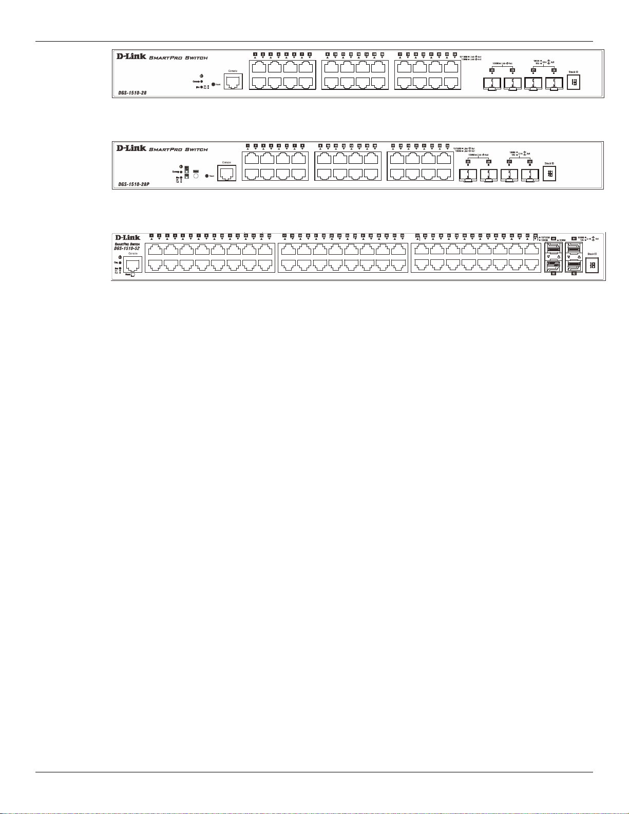
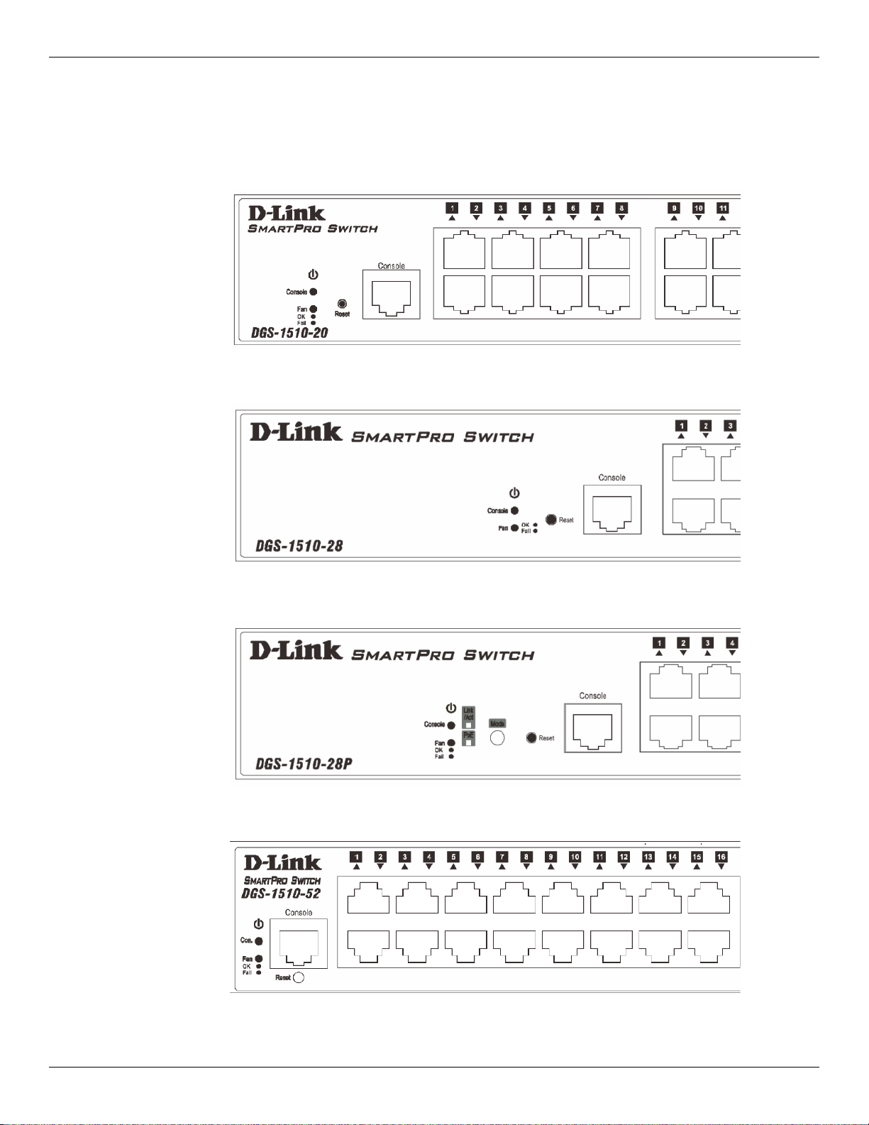
Figure 1–1 Front panel view of a DGS-1510-20 Switch
11
Page 12
DGS-1510 Series Gigabit Ethernet SmartPro Switch Hardware Installation Guide
Figure 1–2 Front panel view of a DGS-1510-28 Switch
Figure 1–3 Front panel view of a DGS-1510-28P Switch
Figure 1–4 Front panel view of a DGS-1510-52 Switch
Ports
The Type and Number of ports available on the Switch are listed out below:
• DGS-1510-20:
o Sixteen Copper Ports (10BASE-T/100BASE-TX/1000BASE-T),
o Two SFP Ports (1000BASE),
o Two Dual Speed SFP+ Ports (1000BASE/10GBASE),
o One Console Port (RJ-45),
• DGS-1510-28:
o Twenty-four Copper Ports (10BASE-T/100BASE-TX/1000BASE-T),
o Two SFP Ports (1000BASE),
o Two Dual Speed SFP+ Ports (1000BASE/10GBASE),
o One Console Port (RJ-45),
• DGS-1510-28P:
o Twenty-four Copper P oE P orts (10BASE-T/100BASE-TX/1000BASE-T),
o Two SFP Ports (1000BASE),
o Two Dual Speed SFP+ Ports (1000BASE/10GBASE),
o One Console Port (RJ-45),
• DGS-1510-52:
o Fourty-eight Copper Ports (10BASE-T/100BASE-TX/1000BASE-T),
o Two SFP Ports (1000BASE),
o Two Dual Speed SFP+ Ports (1000BASE/10GBASE),
o One Console Port (RJ-45),
12
Page 13
DGS-1510 Series Gigabit Ethernet SmartPro Switch Hardware Installation Guide
LED Indicators
The Switch’s front panel presents LED indicators for Power, Console, Master (Stack Control), Stack ID
and Link/Act indicators for all the ports. The DGS-1510-28P switches ar e equi pt with an add iti ona l Po E
light, to indication whether the ports are running in Power over Ethernet mode.
Figure 1–5 LED indicators for a DGS-1510-20 Switch
Figure 1–6 LED indicators for a DGS-1510-28 Switch
Figure 1–7 LED indicators for a DGS-1510-28P Switch
Figure 1–8 LED indicators for a DGS-1510-52 Switch
13
Page 14

DGS-1510 Series Gigabit Ethernet SmartPro Switch Hardware Installation Guide
A separate table below describes LED indicators in more detail.
LED Description
Power
Console
Fan
Link/Act LEDs
This LED will light green after powering the Switch on to indicate the
ready state of the device. The indicator is dark when the Switch is no
longer receiving power (i.e. powered off).
This LED will blink green during the Power-On Self Test (POST).
When the POST is finished, the LED goes dark. The indicator will light
steady green when a user is logged in through the console port.
This LED will light green after the diagnostics have passed with no
errors. This LED blinks red when any of the fans has failed.
The Switch has LED indicators for Link and Activity.
Copper Ports: The LED will light steady green when there is a secure
connection (or link) to a 1000Mbps Ethernet device or steady orange
when there is a secure connection (or link) to a 10/100Mbps Ethernet
device at any of the copper ports. The LED will blink green when a
1000Mbps port is active or blink orange when a 10/10 0Mbps por t is
active. The LED remains dark when there is no link or activity.
SFP Ports: The LED will light steady green when there is a secure
connection (or link) to a 1000Mbps Ethernet device at any of the SFP
ports. The LED remains dark when there is no link or activity.
SFP+ Ports: The LED will light steady green when there is a secure
connection (or link) to a 10Gbps Ethernet device or steady orange
when there is a secure connection (or link) to a 1Gbps Ethernet device
at any of the SFP+ ports. The LED will blink green when a 10Gbps
port is active or blink orange when a 1Gbps port is active. The LED
remains dark when there is no link or activity.
PoE Onl y the DGS-1510-28P switches are equipt with a PoE LED. When
this light is on with a solid green light, it means that the corresponding
ports are feeding power to the PoE devices plugged in. When this light
is on with a solid orange light, it means that the port is in an error
condition state. When this light is off, it means that the ports are not
supplying power to the devices plugged into the ports.
Stack ID
For more information about LED Indicators, refer to LED Indicators
For standalone Switches, this will display number “1”. For stacked
Switches, this indicates the position in the stacking box ID. The box ID
is assigned either by the user (static mode) or by the system
(automatic mode). When “1” to “6” is displayed, this indicates the
stacking position of the switch. An “H” indicates the device was
assigned as the stacking Master. “h“ means the device was selected to
be the Backup Master. A “G” is displayed when the Safeguard Engine
feature enters the exhausted mode. An “E” is displayed when an error
was found during the system self-test.
Rear Panel Components
.
The rear panel contains an AC power socket and a secur it y lock.
14
Page 15

DGS-1510 Series Gigabit Ethernet SmartPro Switch Hardware Installation Guide
Figure 1–9 Rear panel view of a DGS-1510-20 Switch
Figure 1–10 Rear panel view of a DGS-1510-28 Switch
Figure 1–11 Rear panel view of a DGS-1510-28P Switch
Figure 1–12 Rear panel view of a DGS-1510-52 Switch
The AC power connector is a standard three-pronged connector that supports the power cord. Plug-in the
female connector of the provided power cord into this socket, and the male side of the cord into a power
outlet. The Switch automatically adjusts the power setting to any supply voltage in the range from
100~240 VAC at 50~60 Hz.
Side Panel Components
The system heat vents located on the sides of the Switch dissipate heat. Do not block these openings.
Leave at least 6 inches of space at the rear and sides of the Switch for proper ventilation. Without proper
heat dissipation and air circulation, system components might overheat which could lead to system failure
or even severely damaged components.
15
Page 16

DGS-1510 Series Gigabit Ethernet SmartPro Switch Hardware Installation Guide
Figure 1–13 Side panels view of a DGS-1510-20 Switch
Figure 1–14 Side panels view of a DGS-1510-28 Switch
Smart Fans
The DGS-1510 Series Switches includes smart fans that will automatically change their speed
depending on the internal temperature detected by the sensors built-in the Switch’s hardware. These
smart fans support three states. They can either be off, running at a low speed, or running at a high
speed.
Figure 1–15 Side panels view of a DGS-1510-28P Switch
Figure 1–16 Side panels view of a DGS-1510-52 Switch
The following will explain when these fans will toggle between low and high speeds:
• DGS-1510-20: When the internal temperature, detected by the sensor, rises above 47°C, the fan
will automatically change to the high speed. When the internal temperature, detected by the
sensor, falls below 43°C, the fan will automatically change to the low speed.
• DGS-1510-28: When the internal temperature, detected by the sensor, rises above 48°C, the fan
will automatically change to the high speed. When the internal temperature, detected by the
sensor, falls below 43°C, the fan will automatically change to the low speed.
16
Page 17

DGS-1510 Series Gigabit Ethernet SmartPro Switch Hardware Installation Guide
• DGS-1510-28P: When the internal temperature, detected by the sensor, rises above 42°C, the
fan will automatically change to the high speed. When the internal temperature, detected by the
sensor, falls below 39°C, the fan will automatically change to the low speed.
• DGS-1510-52: When the internal temperature, detected by the sensor, rises above 47°C, the fan
will automatically change to the high speed. When the internal temperature, detected by the
sensor, falls below 43°C, the fan will automatically change to the low speed.
17
Page 18

DGS-1510 Series Gigabit Ethernet SmartPro Switch Hardware Installation Guide
2. Installation
Installation Guidelines
Power On (AC Power)
Installation Guidelines
Please follow these guidelines for setting up the Switch:
• Install the Switch on a sturdy, level surface that can support at least 3kg (6.6lb). Do not place
heavy objects on the Switch.
• The power outlet should be within 1.82 meters (6 feet) of the Switch.
• Visually inspect the power cord and see that it is fully secured to the AC power port.
• Make sure that there is proper heat dissipation from and adequate ventilation around the Switch.
Leave at least 10 cm (4 inches) of space at the front and rear of the Switch for ventilation.
• Install the Switch in a fairly cool and dry place for the acceptable temperature and humidity oper-
ating ranges.
• Install the Switch in a site free from strong electromagnetic field generators (such as motors),
vibration, dust, and direct exposure to sunlight.
• When installing the Switch on a level surface, attach the rubber feet to the bottom of the device.
The rubber feet cushion the Switch, protect the casing from scratches and prevent it from scratching other surfaces.
Installing the Switch without a Rack
First, attach the rubber feet included with the Switch if installing on a desktop or shelf. Attach these
cushioning feet on the bottom at each corner of the device. Allow enough ventilation space between the
Switch and any other objects in the vicinity.
Figure 2–1 Attach rubber feet to the Switch.
18
Page 19

DGS-1510 Series Gigabit Ethernet SmartPro Switch Hardware Installation Guide
Attaching Brackets to a Switch for Rack Mounting
The Switch is mounted to a standard 19" rack using mounting brackets. Use the following diagrams as a
guide.
Figure 2–2 Attach mounting brackets to the Switch
Fasten the mounting brackets to the Switch using the screws provided. With the brackets attached
securely, the Switch can be mounted in a standard rack, as shown below.
NOTE: Please review the Installation Guidelines above before installing the Switch in a
rack. Make sure there is adequate space around the Switch to allow for proper air flow,
ventilation and cooling.
Installing the Switch in a Standard 19" Rack
Figure 2–3 Mount the Switch in a rack
19
Page 20

DGS-1510 Series Gigabit Ethernet SmartPro Switch Hardware Installation Guide
CAUTION: Installing systems in a rack without the front and side stabilizers installed could
cause the rack to tip over, potentially resulting in bodily injury under certain circumstances.
Therefore, always install the stabilizers before installing components in the rack. After
installing components in a rack, do not pull more than one component out of the rack on
its slide assemblies at one time. The weight of more than one extended component could
cause the rack to tip over and may result in injury.
Installing Tranceivers into the Transceiver Ports
The Switch is equipped with SFP (Small Form Factor Portable) and SFP+ ports, which are used with
fiber-optical transceiver cabling.SFP ports support full-duplex transmissions, auto-negotiation, and can be
uplinked with various other switches across a gigabit network. The SFP ports support data rates of up to
1Gbit/s and the SFP+ ports support data rates of up to 10Gbit/ s.
See the figure below for installing the transceiver in the transceiver port on the Switch.
Figure 2–4 Inserting fiber-optic transceivers into a Switch
For a full list of supported transceivers, compatible with this switch series, refer to Port Functions
Power On (AC Power)
Plug one end of the AC power cord into the power socket of the Switch and the other end into the local
power source outlet. After the system powered on, the LED’s blink green to indicate that the system is
booting up.
.
20
Page 21

DGS-1510 Series Gigabit Ethernet SmartPro Switch Hardware Installation Guide
Power Failure (AC Power)
In the event of a power failure, just as a precaution, unplug the power cord from the Switch. After the
power returns, plug the power cord back into the power soket of the Switch.
Installing Power Cord Clip
To prevent accidental removal of the AC power cord, it is recommended to install the power cord clip
together with the power cord.
1. With the rough side facing down, insert the Tie Wrap into the hole below the power socket.
Figure 2-5 Insert Tie Wrap to the Switch
2. Plug the AC power cord into the power socket of the Switch.
Figure 2-6 Connect the power cord to the Switch
3. Slide the Retainer through the Tie Wrap until the end of the cord.
21
Page 22

DGS-1510 Series Gigabit Ethernet SmartPro Switch Hardware Installation Guide
Figure 2-7 Slide the Retainer through the Tie Wrap
4. Circle the tie of the Retainer around the power cord and into the locker of the Retainer.
Figure 2-8 Circle around the power cord
5. Fasten the tie of the Retainer until the power cord is secured.
22
Page 23

DGS-1510 Series Gigabit Ethernet SmartPro Switch Hardware Installation Guide
Figure 2-9 Secure the power cord
23
Page 24

DGS-1510 Series Gigabit Ethernet SmartPro Switch Hardware Installation Guide
3. Connecting the Switch
Switch to End Node
Switch to another Switch
Connect to a Network Backbone or Server
Switch to End Node
An End Node can be any networking device, plugged into any of the networking ports of the Switch,
where data transmission ends. Typical end nodes are computers. End nodes are generally outfitted with a
10/100/1000Mbps RJ-45 Ethernet Network Interface Card (NIC) that can connect to the Switch via a
twisted-pair UTP/STP cable. Connect the end node to any of the copper ports of the Switch. The Link/Act
LEDs for each Ethernet port turns green or amber when the link is active. A blinking LED indicates packet
activity on that port.
Figure 3–1 End Node to Switch Connection
Switch to another Switch
There is a great deal of flexibility on how connections are made using the appropriate cabling.
• Connect a 10BASE-T switch port to the Switch via a twisted-pair Category 3, 4 or 5 UTP/STP
cable.
• Connect a 100BASE-TX switch port to the Switch via a twisted-pair Category 5 UTP/STP cable.
• Connect 1000BASE-T switch port to the Switch via a twisted pair Category 5e UTP/STP cable.
• Connect switch supporting a fiber-optic uplink to the Switch’s SFP ports via fiber-optic cabling.
24
Page 25

DGS-1510 Series Gigabit Ethernet SmartPro Switch Hardware Installation Guide
Figure 3–2 Switch to Switch Connection
Connect to a Network Backbone or Server
The Combo Copper/SFP ports are ideal for connecting a network backbone, server or server farm to the
Switch. The copper ports operate at a speed of 10/100/1000Mbps in half-duplex or full-duplex mode. The
fiber-optic ports can operate at both 100/1000Mbps in full-duplex mode. The Link LED turns green when
a connection is made.
Figure 3–3 Server to Switch Connection
25
Page 26

DGS-1510 Series Gigabit Ethernet SmartPro Switch Hardware Installation Guide
4. Introduction to Switch Management
Management Options
Connecting the Console Port
SNMP Settings
Management Options
This Switch can be managed, out-of-band, through the console port on the front panel or in-band using
Telnet. Alternatively, the web-based management can be used, accessible through a web browser.
Command Line Interface (CLI) Management
The user can connect a computer or terminal to the serial console port to access the Switch. The
Command Line Interface (CLI) provides complete access to all Switch management features. When
connecting to the Switch by means of Telnet or SSH, the same CLI can be accessed for Switch
management. For more detailed information about the CLI, refer to the CLI Reference Guide.
SNMP-based Management
The Switch can also be m anage d w ith an SNM P-compatible console program. The Switch supports
SNMP version 1.0, 2.0 and 3.0. The SNMP agent decodes the incoming SNMP messages and responds
to requests with MIB objects stored in the database. The SNMP agent updates the MIB objects to
generate statistics and counters.
Web-based User Interface (Web UI) Management
The user can connect a computer to any one of the frontal ports of the Switch, other than the console
port, to access the Web UI of the Switch by means of a Web browser and entering the IP address of the
Switch. This management interface is a more graphically representation of the features that can be
viewed and configured on this Switch. Most of the features available from the CLI can be accessed
through the Web UI. Web browsers like Microsoft’s Internet Explorer, Mozilla Firefox or Google Chrome
can be used. For more detailed information about the Web UI, refer to the Web UI Reference Guide.
Connecting the Console Port
This section describes how to access the CLI throught the serial port. To connect to the serial port, a
special Console Cable must be used. This cable is included with this product’s packaging. The cable
refered to as an RS-232 to RJ-45 connector cable specifically pinned to connect to this switch’s serial port
by using the correct pin configuration. For more information about the pin layout of this cable, refer to
Appendix B.
To connect to the console port of the Switch, use the following steps:
1. Connect the RS-232 end of the console cable to the Serial Port of the management PC.
2. Connect the RJ-45 end of the console cable to the Console Port of the Switch.
3. Open the HyperTerminal application (or any terminal emulation program capable of emulating a
VT-100 terminal connection) on the management PC and configure the Properies of this
connection.
26
Page 27

DGS-1510 Series Gigabit Ethernet SmartPro Switch Hardware Installation Guide
a. The Bits per second should be 115200 baud.
b. The Data bits should be 8.
c. The Parity should be None.
d. The Stop bits should be 1.
e. The Flow control should be None.
Figure 4-1 Hyperterminal Connection Properties
4. Now the Switch can be turned on and access to the Switch’s CLI will be available.
NOTE: Access to the console port can be made at any time while the Switch is on. There
is no need to turn the Switch off when plugging the console cable into the console port.
Connecting to the Switch for the First Time
After successfully connecting to the Switch’s console and the Switch was turned on, the boot-up
procedure will be displayed, as shown below.
27
Page 28

DGS-1510 Series Gigabit Ethernet SmartPro Switch Hardware Installation Guide
Boot Procedure V1.00.004
-------------------------------------------------------------------------------
Power On Self Test ........................................ 100 %
MAC Address : 00-01-02-03-04-00
H/W Version : A1
Please Wait, Loading V1.00.010 Runtime Image .............. 100 %
UART init ................................................. 100 %
Starting runtime image
Device Discovery .......................................... 100 %
Configuration init ........................................ 100 %
Switch con0 is now available
Press any key to login...
During the boot-up procedure, we can find the PROM version, MAC address, Hardware Version, and
Firmware Version used by this Switch.
By default, there is no login username or password configured on t h is Switch. The CLI prompt will
immediately be available, as shown below.
DGS-1510-28P Gigabit Ethernet SmartPro Switch
Command Line Interface
Firmware: Build 1.00.010
Copyright(C) 2014 D-Link Corporation. All rights reserved.
Switch>
Now the switch can be configured.
CAUTION: For security reasons, it is highly recommended to configure a personal
username and password for this Switch.
Creating a User Account
This section will discuss how to create a login username and password on this Switch. This login details
will be applied not only for access to the CLI, but also for access to the Web UI, Telnet, SSH, and SSL
interfaces. The same username and password will be used for these connections.
28
Page 29

DGS-1510 Series Gigabit Ethernet SmartPro Switch Hardware Installation Guide
By default, there are no user accounts configured on this Switch. To create a user account, enter the
following commands.
Switch> enable
Switch# configure terminal
Switch(config)# username nick password pass
Switch(config)# username nick privilege 15
Switch(config)# line console
Switch(config-line)# login local
Switch(config-line)#
In the above example,
1. We accessed the Privileged EXEC Mode by entering the command enable.
2. Then we entered the Global Configuration Mode by entering the command configure terminal.
3. Then we created a user account with the username of ‘Administrator’ and gave it the password
of ‘12345’ by entering the command username Administrator password 12345.
4. Then we assigned the privilege level of 15 to this user account by entering the command
username Administrator privilege 15. The highest level access is 15 and the lowest level
access is 1.
5. Then we entered the LINE Configuration Mode by entering the command line console.
6. Then we configured the Switch to allow access to the management interface by using locally
configured user accounts. The command is login local.
NOTE: CLI configuration commands only modify the running configuration file and are not
saved when the Switch is rebooted. To save all your configuration changes in non-volatile
storage, you must use the copy running-configuration start-up-configuration
command to copy the running configuration file to the start-up configuration. For more
information, refer to the CLI Reference Guide.
Configuring the IP Address
Each networking node, within a network, must use a unique IP Address. This IP address is used to
communicate with other networking devices in the network. The IP address of the Switch is also important
to be able to access the Web UI of this Switch. There are two methods in which a Switch can obtain an IP
address.
1. The Switch can obtain an IP address from a DHCP server located within the local network. By
default, this option is not enabled.
2. The administrator can manually configure an IP address for this Switch.
To find out what the IP address of the Switch is, we again need to access the Switch management
interface through the CLI. Take note of the following example.
29
Page 30

DGS-1510 Series Gigabit Ethernet SmartPro Switch Hardware Installation Guide
Switch> show ip interface
Interface vlan1 is enabled, Link status is down
IP Address is 10.90.90.90/8 (Manual)
ARP timeout is 20 minutes.
Proxy ARP is disabled
IP Local Proxy ARP is disabled
gratuitous-send is disabled, interval is 0 seconds
Total Entries: 1
Switch>
In the above example, the command show ip interface is used to display information about the IP
interfaces created on this Switch. In this display we see that the IP address for this switch is 10.90.90.90
and the CIDR notation for the subnet mask is /8 which translates to 255.0.0.0. This information can
however be modified, as show below.
Switch> enable
Switch# configure terminal
Switch(config)# interface vlan 1
Switch(config-if)# ip address 192.168.1.1 255.255.255.0
Switch(config-if)#
In the above example,
1. We accessed the Privileged EXEC Mode by entering the command enable.
2. Then we entered the Global Configuration Mode by entering the command configure terminal.
3. Then we entered the VLAN Configuration Mode of the default VLAN, which isVLAN 1, by
entering the command interface vlan 1.
4. Then we changed the IP address of the Switch to 192.168.1.1 and the subnet mask to
255.255.255.0 by entering the command ip address 192.168.1.1 255.255.255.0.
SNMP Settings
The Simple Network Management Protocol (SNMP) is an OSI Layer 7 (Application Layer) designed
specifically for managing and monitoring network devices. SNMP enables network management stations
to read and modify the settings of gateways, routers, switches and other network devices. Use SNMP to
configure system features for proper operation, monitor performance and detect potential problems in the
Switch, switch group or network.
Managed devices that support SNMP include software (referred to as an agent), which runs locally on the
device. A defined set of variables (managed objects) is maintained by the SNMP agent and used to
manage the device. These objects are defined in a Management Information Base (MIB), which provides
a standard presentation of the information controlled by the on-board SNMP agent. SNMP defines both
the format of the MIB specifications and the protocol used to access this information over the network.
30
Page 31

DGS-1510 Series Gigabit Ethernet SmartPro Switch Hardware Installation Guide
The Switch supports SNMP versions 1, 2c, and 3. The administrator may specify which SNMP version to
use to monitor and control the Switch. The three SNMP versions vary in the level of security provided
between the management station and the network device.
In SNMPv1 and SNMPv2, user authentication is accomplished using 'community strings', which function
like passwords. The remote user SNMP application and the Switch SNMP must use the same community
string. SNMP packets from any station that has not been authenticated are ignored (dropped).
The default community strings for the Switch used for SNMPv1 and SNMPv2 management access are:
• public - Allows authorized management stations to retrieve MIB objects.
• private - Allows authorized management stations to retrieve and modify MIB objects.
SNMPv3 uses a more sophisticated authentication process that is separated into two parts. The first part
is to maintain a list of users and their attributes that are allowed to act as SNMP managers. The second
part describes what each user on that list can do as an SNMP manager.
The Switch allows groups of users to be listed and configured with a shared set of privileges. The SNMP
version may also be set for a listed group of SNMP managers. Thus, a group of SNMP managers can be
created to view read-only information or receive traps using SNMPv1 while assigning a higher level of
security to another group, granting read/write privileges using SNMPv3.
Using SNMPv3 individual users or groups of SNMP managers can be allowed to perform or be restricted
from performing specific SNMP management functions. The functions allowed or restricted are defined
using the Object Identifier (OID) associated with a specific MIB. An additional layer of security is available
for SNMPv3 in that SNMP messages ma y be encrypte d.
Traps
Traps are messages that alert network personnel of events that occur on the Switch. The events can be
as serious as a reboot (someone accidentally turned OFF the Switch), or less serious like a port status
change. The Switch generates traps and sends them to the trap recipient (or network manager). Typical
traps include trap messages for Authentication Failure, Topology Change and Broadcast\Multicast Storm.
Management Information Base (MIB)
The Switch in the Management Information Base (MIB) stores management and counter information. The
Switch uses the standard MIB-II Management Information Base module. Consequently, values for MIB
objects can be retrieved from any SNMP-based network management software. In addition to the
standard MIB-II, the Switch also supports its own proprietary enterprise MIB as an extended Management
Information Base. The proprietary MIB may also be retrieved by specifying the MIB Object Identifier. MIB
values can be either read-only or read-write.
NOTE: For customers interested in D-View, D-Link Corporation's proprietary SNMP
management software, go to http://dview.dlink.com.tw/
manual.
31
and download the software and
Page 32

DGS-1510 Series Gigabit Ethernet SmartPro Switch Hardware Installation Guide
D-Link Network Assistant (DNA)
The D-Link Network Assistant (DNA), included in the installation CD, is a program that allows
administrators to quickly discover all D-Link Switches and D-Link Discover Protocol (DDP) supported
devices that are in the same subnet as the management computer to collect traps and log messages and
provide quick access to basic configurations of the switch. This utility can only be used on computers
running Microsoft’s Windows 7, Vista, XP, or 2000 on both 32bit and 64bit systems. There are two
options for the installation of the DNA; one is through the Autorun program on the installation CD and the
other is manual installation.
NOTE: Please be sure to uninstall any existing DNA from your PC before installing the
latest DNA.
For detailed explanations of the DNA functions and a list of supported DDP devices, refer to the D-Link
Network Assistant (DNA) User Guide.
32
Page 33

DGS-1510 Series Gigabit Ethernet SmartPro Switch Hardware Installation Guide
5. Web-based Switch Configuration
Introduction
Logging onto the Web Manager
Web-based User Interface
Introduction
Most software functions of the Switch can be managed, configured, and monitored via the embedded
Web-based (HTML) interface. Manage the Switch from remote stations anywhere on the network through
a standard browser, such as Internet Explorer (version 5.5 and later), Mozilla Firefox (version 3 and later),
Chrome (version 5 and later), or Safari (version 4 and later). The browser acts as a universal access tool
and can communicate directly with the Switch using the HTTP protocol.
Logging onto the Web Manager
To begin managing the Switch, simply run the browser installed on your computer and point it to the IP
address you have defined for the device. The URL in the address bar should be in the format of
http://123.123.123.123, where the numbers 123 represent the IP address of the Switch.
NOTE: The factory default IP address is 10.90.90.90.
This opens the user authentication window, as seen below. The following example is from 10.90.90.90.
Figure 5–1 Enter Network Password Window
Leave the User Name and Password fields blank and click Login. This will open the Web-based user
interface. The Switch management features available in the web-based manager are explained below.
33
Page 34

DGS-1510 Series Gigabit Ethernet SmartPro Switch Hardware Installation Guide
Web-based User Interface
The user interface provides access to various Switch configuration and management windows, it allows
the user to view performance statistics, and permits graphical monitoring of the system status.
Areas of the User Interface
The figure below shows the user interface. Three distinct areas divide the user interface, as described in
the table.
AREA 2
AREA 4
AREA 1
Figure 5–2 Main Web-manager Window
Area Function
AREA 1
AREA 2
AREA 3
Select the folder or window to display. Open folders and click the
hyperlinked window buttons and subfolders contained within them to
display windows.
Presents a graphical near real-time image of the front panel of the
Switch. This area displays the Switch's ports and expansion modules
and shows port activity, depending on the specified mode. Some
management functions, including port monitoring are accessible here.
Click the D-Link logo to go to the D-Link Website.
Presents Switch status based on user selection and the entry of
configuration data. In addition, hyperlinks are offered for many Switch
features to enable quick configuration.
AREA 3
AREA 4 Presents a toolbar used to access function like Save, Tools, the
Wizard, Online Help, and Language preference.
34
Page 35

DGS-1510 Series Gigabit Ethernet SmartPro Switch Hardware Installation Guide
Web Pages
When connecting to the management mode of the Switch with a Web browser, a login screen is
displayed. Enter a user name and password to access the Switch's management mode.
Below is a list of the main folders available in the Web interface:
System
Management
L2 Features
L3 Features
QoS
ACL
Security
OAM
Monitoring
In this section the user will be able to configure features regarding the
Switch’s configuration.
In this section the user will be able to configure features regarding the
Switch’s management.
In this section the user will be able to configure features regarding the
Layer 2 functionality of the Switch.
In this section the user will be able to configure features regarding the
Layer 3 functionality of the Switch.
In this section the user will be able to configure features regarding the
Quality of Service functionality of the Switch.
In this section the user will be able to configure features regarding the
Access Control List functionality of the Switch.
In this section the user will be able to configure features regarding the
Switch’s security.
In this section the user will be able to configure features regarding the
Switch’s operations, administration and maintenance (OAM).
In this section the user will be able to monitor the Switch’s
configuration and statistics.
Green
In this section the user will be able to view and configure the Switch’s
power saving and Energy Effiecient Eth er net (EEE) fea t ures .
35
Page 36

DGS-1510 Series Gigabit Ethernet SmartPro Switch Hardware Installation Guide
Appendix A – Technical Specifications
General
Feature Detailed Description
Standards
IEEE 802.1AB L ink Layer Discovery Protocol.
IEEE 802.1D-2004 Spanning Tree Protocol.
IEEE 802.1p Priority Queues.
IEEE 802.1Q-2005 Virtual LAN.
IEEE 802.1S Multiple Spanning Tree Protocol.
IEEE 802.1W Rapid Spanning Tree Protocol.
IEEE 802.1X Port-based Authentication.
IEEE 802.3i 10BASE-T Ethernet.
IEEE 802.3u 100BASE-TX Fast Ethernet.
IEEE 802.3ab 1000BASE-T Gigabit Ethernet.
IEEE 802.3ad Link Aggregation.
IEEE 802.3ae 10GBASE-X/10GBASE-R/10GBASE-W.
IEEE 802.3af Power over Ethernet.
IEEE 802.3at Power over Ethernet.
IEEE 802.1az Energy-Efficient Ethernet.
IEEE 802.3x Flow Control support for Full-Duplex mode.
Data Transfer Rates
Stacking Topology
Network Cables
IEEE 802.3z 1000BASE-T Gigabit Ethernet.
Ethernet
Fast Ethernet
Gigabit Ethernet
10 Gigabit Ethernet
Duplex Ring, Duplex Chain
UTP/STP Category 3, 4, 5 for 10BASE-T
UTP/STP Category 5 Enhanced for 1000BASE-T
UTP/STP Category.5, 5 Enhanced for 100BASE-TX
EIA/TIA-568 100Ω screened twisted-pair (STP) (100m)
Half-duplex Full-duplex
10Mbps 20Mbps
100Mbps 200Mbps
------------- 2Gbps
------------- 20Gps
36
Page 37

DGS-1510 Series Gigabit Ethernet SmartPro Switch Hardware Installation Guide
Physical and Environmental
Feature Detailed Description
Internal Power Supply DGS-1510-20: 100-240 VAC, 50/60 Hz, 24 Watt.
DGS-1510-28: 100-240 VAC, 50/60 Hz, 30 Watt.
DGS-1510-28P: 100-240 VAC, 50/60 Hz, 253 Watt.
DGS-1510-52: 100-240 VAC, 50/60 Hz, 54 Watt.
Fans
Maximum Power
Consumption
Standby Power
Consumption
Temperature Operating: -5°C ~ 50°C (23°F ~ 122°F)
The IC Sensor detects the temperature on the switch automatically,
and adjusts the speed. The amount of fans that are installed per
Switch are listed below:
DGS-1510-20: 1 Fan.
DGS-1510-28: 1 Fan.
DGS-1510-28P: 2 Fans.
DGS-1510-52: 2 Fans.
DGS-1510-20: 20.3 Watt.
DGS-1510-28: 24.0 Watt.
DGS-1510-28P: 29.0 Watt (PoE off). 238.7 Watt (PoE on).
DGS-1510-52: 38.4 Watt.
DGS-1510-20: 11.4 Watt (100V). 12.2 Watt (240V).
DGS-1510-28: 14.6 Watt (100V). 15.2 Watt (240V).
DGS-1510-28P: 22.7 Watt (100V). 21.0 Watt (240V).
DGS-1510-52: 27.3 Watt (100V). 27.6 Watt (240V).
Storage: -20°C ~ 70°C (-4°F ~ 158°F)
Humidity Operating: 0% ~ 95% (non-condensing)
Storage: 0% ~ 95% (non-condensing)
Dimensions DGS-1510-20: 280mm (W) 180mm (D) 44mm (H)
DGS-1510-28: 440mm (W) 210mm (D) 44mm (H)
DGS-1510-28P: 440mm (W) 210mm (D) 44mm (H)
DGS-1510-52: 440mm (W) 210mm (D) 44mm (H)
Weight DGS-1510-20: 1.235 kg
DGS-1510-28: 2.000 kg
DGS-1510-28P: 2.536 kg
DGS-1510-52: 2.400 kg
MTBF DGS-1510-20: 882152.3682 Hours
DGS-1510-28: 516593.2513 Hours
37
Page 38

DGS-1510 Series Gigabit Ethernet SmartPro Switch Hardware Installation Guide
DGS-1510-28P: 243090.6950 Hours
DGS-1510-52: 433434.1606 Hours
EMI/EMC; Test Reports
Safety Certifications and
Test Reports
Performance
Feature Detailed Description
Transmission Method
Packet Buffer DGS-1510-20/28/28P: 1.5 Mb ytes per device.
Wire Speed
Switching Capacity DGS-1510-20: 76 Gbps.
CE Class A, FCC Class A, VCCI Report Class A, C-Tick Report Class
A, BSMI, CCC
UL/CSA 60950-1, IEC 60950-1:2001, BSMI
Store-and-forward.
DGS-1510-52: 3 MBytes per device.
Wire speed operation on all FE/GE/10GE ports.
DGS-1510-28: 92 Gbps.
DGS-1510-28P: 92 Gbps.
DGS-1510-52: 140 Gbps.
64 Byte System Packet
Forwarding Rate
Priority Queues
MAC Address Table
Virtual Stacking /
Clustering
DGS-1510-20: 56.54 Mpps (Mega Packets Per Second)
DGS-1510-28: 68.45 Mpps (Mega Packets Per Second)
DGS-1510-28P: 68.45 Mpps (Mega Packets Per Second)
DGS-1510-52: 104.16 Mpps (Mega Packets Per Second)
8 Priority Queues per port.
Supports 16K MAC addresses.
Supports 512 Static MAC addresses.
Supports D-Link Single IP Management version 1.6.
Manage up to 32 devices in a virtual stack with a single IP address.
LED Indicators
Location LED Indicative Color Status Description
Per Device Power Green
Solid Light Power on.
Blinking Performing System Self-test.
38
Page 39

DGS-1510 Series Gigabit Ethernet SmartPro Switch Hardware Installation Guide
Light off Power off.
Console Green
Fan Green
Red
Stacking ID Green
Solid Light Console on.
Light off Console off.
Solid Light Diagnostics pass. Normal operation.
Solid Light Fan failure.
Capable 1 – 6, H, h,
E, G.
The box ID is assigned either by user
(static mode) or by the system
(automatic mode). When the box
become a primary master, the 7
segment works as bi-function. That is
box ID and “H” indicate as primary
Master and the display will be shown
by turn.
That is boxID -> H -> boxID -> H.
1-6: To indicate the stacking of the
switch.
H: When device was assigned as the
stacking Master.
h: When device was selected to be the
Backup Master.
LED Per
10/100/1000 Mbps
Port
Port LED Mode
Indicator
Link/Act/Speed Mode Green
A LED Mode Select Button to switch two modes in turn for all
10/100/1000Mbps ports on DGS-1510-28P:
Link/Act/Speed Mode
PoE Mode (Only DGS-1510-28P)
Green
E: Error was found during system selftest.
G: When Safeguard Engine entering
the exhausted mode.
Solid Light A LED Mode Select Button to switch
Link/Act/Speed Mode
Solid Light A LED Mode Select Button to switch
PoE Mode
Solid Light When there is a secure connection (or
link) to 1000Mbps Ethernet device at
any of the ports.
Blinking When there is reception or
transmission of data occurring at
1000Mbps.
Orange
Solid Light When there is a secure connection (or
link) to 10/100Mbps Ethernet device at
any of the ports.
Blinking When there is reception or
39
Page 40

DGS-1510 Series Gigabit Ethernet SmartPro Switch Hardware Installation Guide
transmission of data occurring at
10/100Mbps.
Off
PoE Mode
(Only DGS-1510-28P)
LED per SFP Port Link/Act Green
LED per SFP+
Port
Link/Act Green
Green
Orange
Off
Orange
Light off No link.
Solid Light Power feeding.
Solid Light Error Condition.
Light Off No Power feeding.
Solid Light When there is a secure connection (or
link) to 1000Mbps Ethernet device at
any of the ports.
Blinking When there is reception or
transmission of data occurring at
1000Mbps.
Solid Light When there is a secure connection (or
link) to 10G bps Ethernet device at any
of the ports.
Blinking When there is reception or
transmission (i.e. Activity--Act) of data
occurring at a 10G bps port.
Solid Light When there is a secure connection (or
link) to 1000Mbps Ethernet device at
any of the ports.
Port Functions
Feature Detailed Description
Console Port
Copper Ports
Blinking When there is reception or
transmission (i.e. Activity--Act) of data
occurring at a 1000Mbps port.
Off
RJ-45 interface for Out-Of-Band (OOB) CLI configuration.
Compliant with the following standards:
• IEEE 802.3 compliance
• IEEE 802.3u compliance
• IEEE 802.3ab compliance
• IEEE 802.3az compliance (100/1000Mbps)
Light off Link down
Support Full-Duplex operations:
• IEEE 802.3x Flow Control support for Full-Duplex mode
40
Page 41

DGS-1510 Series Gigabit Ethernet SmartPro Switch Hardware Installation Guide
• IEEE 802.3af compliance (DGS-1510-28P)
80m:
• DEM-436XT-BXU (10GBASE-LR BiDi SFP+ Transceiver (w/o
• IEEE 802.3at compliance (DGS-1510-28P)
SFP Ports
Compliant with the following standards:
• IEEE 802.3z compliance
SFP Transceivers Supported:
• DEM-302S-LX (1000BASE-LX, Single-mode, 2km)
• DEM-310GT (1000BASE-LX, Single-mode, 10km)
• DEM-311GT (1000BASE-SX, Mutli-mode, 550m)
• DEM-312GT2 (1000BASE-SX, Multi-mode, 2km)
• DEM-314GT (1000BASE-LHX, Single-mode, 50km)
• DEM-315GT (1000BASE-ZX, Single-mode, 80km)
• DGS-712 (1000BASE-TX)
WDM Transceivers Supported:
• DEM-302S-BXD/BCU (1 000BASE-BX, Single-mode, 2km)
• DEM-330T/R (1000BASE-BX, Single-Mode, 10km)
• DEM-331T/R (1000BASE-BX, Single-Mode, 40km)
SFP+ Ports
Compliant with the following standards:
• IEEE 802.3ae compliance
• IEEE 802.3z compliance
SFP Transceivers Supported:
All SFP and WDM transceivers listed in the SFP Ports section (above)
will also work in the SFP+ ports.
SFP+ Transceivers Supported:
• DEM-431XT-DD (10GBASE-SR SFP+ Transceiver, 80m: OM1
& OM2 MMF 300m: OM3 MMF)
• DEM-431XT (10GBASE-SR SFP+ Transceiver (w/o DDM),
OM1 & OM2 MMF 300m: OM3 MMF)
• DEM-432XT-DD (10GBASE-LR SFP+ Transceiver, 10km)
• DEM-432XT (10GBASE-LR SFP+ Transceiver (w/o DDM),
10km)
• DEM-433XT-DD (10GBASE-ER SFP+ Transceiver, 40km)
• DEM-433XT (10GBASE-ER SFP+ Transceiver (w/o DDM),
40km)
• DEM-434XT (10GBASE-ZR SFP+ Transceiver (w/o DDM),
80km)
41
Page 42

DGS-1510 Series Gigabit Ethernet SmartPro Switch Hardware Installation Guide
DDM), 20km, TX: 1270nm, RX: 1330nm)
per
• DEM-436XT-BXD (10GBASE-LR BiDi SFP+ Transceiver (w/o
DDM), 20km, TX: 1330nm, RX: 1270nm)
SFP+ Direct Attached Cables (DAC) Supported:
• DEM-CB100S-10-GbE (SFP+, 1m, Direct Attach Cable), for
stacking.
• DEM-CB300S-10-GbE (SFP+, 3m Direct Attach Cable), for
stacking.
• DEM-CB700S-10-GbE (SFP+, 7m Direct Attach Cable), for
stacking.
PoE Ports
(DGS-1510-28P Only)
1. Supports IEEE 802.3af PoE and IEEE 802.3at PoE+
compliance.
2. Supplies power (ports 1 to 24) to PD de vices up to 15.4 Watt
port (802.3af) or 30 Watt per port (802.3at) and more sufficiently
is able to provide po wer to PD devic es.
3. The auto-discovery feature automatically recognizes the
connection of the PD device and immediately provides power.
4. Automatically disable ports if the port current is over 600mA
while. Other ports will remain active.
5. Active circuit protection automatically disables the port if there is
a short while other ports remain active.
6. For 802.3af/at capable devices it will provide the power for the
following classifications below:
Class Usage Max Power used by PD
0 Default 0.44 Watt to 12.95 Watt
1 Optional 0.44 Watt to 3.84 Watt
2 Optional 3.84 Watt to 6.49 Watt
3 Optional 6.49 Watt to 12.95 Watt
4 Optional (802.3at
Only)
7. Follow the PSE pin out standard. For an alternative solution,
send the power over pins 1, 2, 3, 6 and 8 wires. Use Category 3,
6A UTP cable for 802.3af or Category 5e, 6A UTP cable for
802.3at.
8. The DGS-1510-28P works with all D-Link 802.3af and 802.3at
capable devices and with all non-802.3af and non-802.3at
capable D-Link Access Points, IP Cameras and IP Phones.
9. The total power budget is 193 Watts.
42
12.95 Watt to 25.5 Watt
Page 43

DGS-1510 Series Gigabit Ethernet SmartPro Switch Hardware Installation Guide
Appendix B – Cables and Connectors
Ethernet Cable
When connecting the Switch to another switch, a bridge or hub, a normal cable is necessary. Please
review these products for matching cable pin assignment. The following diagrams and tables show the
standard RJ-45 connector and their pin assignments.
Figure B–1 Standard RJ-45 port and connector
RJ-45 PIN Assignments:
Pin MDI-X Port MDI-II Port
1 RD+ (receive) TD+ (transmit)
2 RD- (receive) TD- (transmit)
3 TD+ (transmit) RD+ (receive)
4 1000BASE-T 1000BASE-T
5 1000BASE-T 1000BASE-T
6 TD- (transmit) RD- (receive)
7 1000BASE-T 1000BASE-T
8 1000BASE-T 1000BASE-T
43
Page 44

DGS-1510 Series Gigabit Ethernet SmartPro Switch Hardware Installation Guide
Console Cable
When connecting the Switch to a PC, a Console cable is necessary. The following diagrams and tables
show the standard Console-to-DJ-45 receptacle/connector and their pin assignments.
Figure B–2 Console-to-RJ-45 Cable
Console-to-RJ-45 PIN Assignments:
Pin Console (DB9/RS232) RJ-45
1 Not Used Not Used
2 RXD Not Used
3 TXD TXD
4 Not Used GND
5 GND (shared) GND
6 Not Used RXD
7 Not Used Not Used
8 Not Used Not Used
44
Page 45

Subject to the terms and conditions set forth herein, D-Link Systems, Inc. (“D-Link”) provides this Limited Warranty:
• Only to the person or entity that originally purchased the product from D-Link or its authorized reseller or distributor, and
• Only for products purchas ed and delivered within the fifty states of the United States, the District of Col umbia, U.S. Possessions or Protectorates,
U.S. Military Installations, or addresses with an APO or FPO.
Limited Warranty: D-Link warrants that the hardware portion of the D-Link product described below (“Hardware”) will be free from material defects in
workmanship and materials under normal use from the date of original retail purchase of the product, for the period set forth below (“Warra nty Period”),
except as otherwise stated herein.
Limited Lifetime Warranty for the product is defined as follows:
• Hardware: For as long as the original customer/end user owns the product, or five (5) years after product discontinuance, whichever occurs first
(excluding power supplies and fans)
• Power supplies and fans: Three (3) Year
• Spare parts and spare kits: Ninety (90) days
The customer's sole and exclusive remedy and the entire liabili ty of D-Link and its suppliers under this Limited Warranty will be, at D-Li nk’s option, to
repair or replace the defective Hardware during the Warranty Period at no cha rge to the original owner or to refund the actual purcha se price paid. Any
repair or replacement will be rendered by D-Link at an Authorized D-Link Service Office. The replace m ent hardware n eed not be ne w or have an i dentic al
make, model or part. D-Link may, at its option, replace the defective Hardware or an y part thereof with any reconditioned product th at D-Link reasonabl y
determines is substantially equivalent (or superior) in all material respects to the defective Hardware. Repaired or replacement hardware will be
warranted for the remainder of the original Warranty Period or ninety (90) days, whichever is longer, and is subject to the same limitations and exclusio ns.
If a material defect is incapable of correction, or if D-Link determi nes that it is not practical to repair or replace the defective Hard ware, the actual price
paid by the original purchaser for the defective Hardware will be refunded by D-Link upon return to D-Link of the defective Hardware. All Hardware or part
thereof that is replaced by D-Link, or for which the purchase price is refunded, shall become the property of D-Link upon replacement or refund.
Limited Software Warranty: D-Link warrants that the software portion of the product (“Software”) will substantially conform to D-Link’s then current
functional specifications for the Software, as set forth in the applicable documentation, from the date of original retail purchase of the Software for a period
of ninety (90) days (“Software Warranty Period”), provided that the Software is properl y installed on approved hard ware and operated as c ontemplated in
its documentation. D-Link further warrants that, during the Software Warranty Period, the magnetic m edia on which D-Link delivers the Software will be
free of physical defects. The customer's sole and exclusive remedy and the entire liabili ty of D-Link and its suppliers under this Limi ted Warranty will be,
at D-Link’s option, to replace the non-conforming Software (or defective media) with software that substantially conforms to D-Link’s functional
specifications for the Software or to refund the portion of the actual purchase pric e paid that is attributable to the Softwa re. Except as otherwise agreed
by D-Link in writing, the replacement Software is provided onl y to the origi nal li censee, and i s s ubjec t to the terms and condi tions of the li cens e granted by
D-Link for the Software. Replacement Software will be warranted for the remainder of the ori ginal Warranty Period and is subj ect to the same limitations
and exclusions. If a material non-conformance is incapable of correction, or if D-Link determines in its sol e discretion that it is not practical to replace the
non-conforming Software, the price paid by the original licensee for the non-c onforming Software will be refunded by D-Link; provided that the nonconforming Software (and all copies thereof) is first returned to D-Link. The license granted respecting any Software for which a refund is given
automatically terminates.
Non-Applicability of Warranty: The Limited Warranty provided hereunder for Hardware and Software portions of D-Link's products will not be applied to
and does not cover any refurbished product and any product purchased through the inventory clearance or liquidation sale or other sales in which D-Link,
the sellers, or the liquidators expressly disclaim their warranty obligati on pertaining to the product and in that case, the product is being sold "As-Is"
without any warranty whatsoever includi ng, without limitation, the Limited Warranty as described herein, notwithstanding anything stated herein to the
contrary.
Submitting A Claim: The custo mer shall return the pro duct to the original purchase poi nt based on its return polic y. In case the retur n policy period has
expired and the product is within warranty, the customer shall submit a claim to D-Link as outlined below:
• The customer m ust s ubmit with t he product as pa rt of the c lai m a written des cripti on of the Hardwar e defec t or Soft ware nonc onfo rma nce i n suffic ient
detail to allow D-Link to confirm the same, along with proof of purchas e of the product (such as a copy of the dated purchase invoice for the product )
if the product is not registered.
• The customer must obtai n a Case ID Number from D-Link Technical Support at 1-877-453-5465, who will attempt to assist the customer in resolving
any suspected defects with the product. If the product is considered defective, the customer mus t obtain a Return Material Authorization (“RMA”)
number by completing the RMA form and entering the assigned Case ID Number at
• After an RMA number is issued, the defective product must be packaged s ecurely in the original or other s uitable shipping package to ens ure that it
will not be damaged in transit, and the RMA number must be prominently marked on the outside of the pack age. Do not include any manuals or
accessories in the shipping package. D-Link will only replace the defective portion of the product and will not ship back any accessories.
• The customer is responsible for all in-bound s hipping charges to D-Link. No Cash on Del ivery (“COD”) is allowed. Products s ent COD will either be
rejected by D-Link or become the property of D-Link. Products shall be fully insured by the customer and shipped to D-Link Systems, Inc., 17595
Mt. Herrmann, Fountain Valley, CA 92708. D-Link will not be held responsible for any packages that are l ost in transit to D-Link. The repair ed or
replaced packages will be shipped to the customer via UPS Ground or an y common carrier selected by D-Link. Return shipping charges shall be
prepaid by D-Link if you use an address in the United States, otherwise we will ship the product to you freight collec t. Expedited shipping is av ailable
upon request and provided shipping charges are prepaid by the customer.
D-Link may reject or return any product that is not packaged and shipped in strict compliance with the foregoing requirements, or for which an RMA
number is not visible from the outside of the package. The product owner agrees to pay D -Link’s reasonable handling and return shi pping c harges for an y
product that is not packaged and shipped in accordance with the foregoing requirements, or that is determined by D-Link not to be defec tive or nonconforming.
What Is Not Covered: The Limited Warranty provided herein by D-Link does not cover: Products that, in D-Link’s judgment, have been s ubjected to
abuse, accident, alteration, modification, tampering, negligence, misuse, faulty installation, lack of reasonabl e care, repair or servi ce in any way that is not
contemplated in the documentation for the product, or if the model or serial number has been altered, tampered with, defaced or removed; Initial
installation, installation and removal of the product for repair, and shipping costs; Operational adjustm ents c overed in the operating manual for the product,
and normal maintenance; Damage that occurs in shipment, due to act of God, failures due to power surge, and cosmetic damage; Any hardware,
software, firmware or other products or services provided by anyone other than D-Link; and Products that have been purchas ed from inventory clearanc e
or liquidation sales or other sales in which D-Link, the sellers, or the liquidators expressl y disclaim their warranty obligation pertaining to the product.
While necessary maintenance or repairs on your Product can be performed by any company, we recommend that you use only an Authorized D-Link
Service Office. Improper or incorrectly performed maintenance or repair voids this Limited Warranty.
Disclaimer of Other Warranties: EXCEPT FOR THE LIMITED WARRANTY SPE CIFIED HEREIN, THE PRODUCT IS PROVIDED “AS-IS” WI THOUT
ANY WARRANTY OF ANY KIND WHATSOEVER INCLUDING, WITHOUT LIMITATION, ANY WARRANT Y OF MERCHANTABILITY, FITNESS FOR A
PARTICULAR PURPOSE AND NON-INFRINGEMENT. IF ANY IMPLIED WARRANTY CANNOT BE DISCLAIMED IN ANY TERRITORY WHERE A
PRODUCT IS SOLD, THE DURATION OF SUCH IMPLIED WARRANTY SHALL BE LIMITED TO NINETY (90) DAYS. EXCEPT AS EXPRESSLY
COVERED UNDER THE LIMITED WARRANTY PROVIDED HEREIN, THE ENTIRE RISK AS TO THE QUALITY, SELECT ION AND PERFORMANCE
OF THE PRODUCT IS WITH THE PURCHASER OF THE PRODUCT.
https://rma.dlink.com/.
 Loading...