

Page 1
1
Page 2

DGS-1100 MP/MPP Series Switch Web UI Reference Guide
Information in this document is subject to change without notice.
© 2015 D-Link Corporation. All rights reserved.
Reproduction in any manner whatsoever without the written permission of D-Link Corporation is strictly
forbidden.
Trademarks used in this text: D-Link and the D-Link log o are tr ademark s of D-Link Corporation; Microsoft and
Windows are registered trademarks of Microsoft Corporation.
Other trademarks and trade names may be used in this document to refer to either the entities claiming the
marks and names or their products. D-Link Corporation disclaims any proprietary interest in trademarks and
trade names other than its own.
FCC Warning
This equipment has been tested and found to comply with the limits for a Class A digital device, pursuant to
Part 15 of the FCC Rules. These limits are designed to provide reasonable protection against harmful
interference when the equipment is operated in a commercial environment. This equipment generates, uses,
and can radiate radio frequency energy and, if not installed and used in accordance with this user’s guide, may
cause harmful interference to radio communications. Operation of this equipment in a residential area is likely
to cause harmful interference in which case the user will be required to correct the interference at his own
expense.
CE Mark Warning
This is a Class A product. In a domestic environment, this product may cause radio interference in which case
the user may be required to take adequate measures.
Warnung!
Dies ist ein Produkt der Klasse A. Im Wohnbereich kann dieses Produkt Funkstoerungen verursachen. In
diesem Fall kann vom Benutzer verlangt werden, angemessene Massnahmen zu ergreifen.
Precaución!
Este es un producto de Clase A. En un entorno doméstico, puede causar interferencias de radio, en cuyo case,
puede requerirse al usuario para que adopte las medidas adecuadas.
Attention!
Ceci est un produit de classe A. Dans un environnement domestique, ce produit pourrait causer des
interférences radio, auquel cas l`utilisateur devrait prendre les mesures adéquates.
Attenzione!
Il presente prodotto appartiene alla classe A. Se utilizzato in ambiente domestico il prodotto può causare
interferenze radio, nel cui caso è possibile che l`utente debba assumere provvedimenti adeguati.
VCCI Warning
May, 2015
ii
Page 3

DGS-1100 MP/MPP Series Switch Web UI Reference Guide
Table of Contents
1. Introduction ................................................................................................................................................................... 1
Audience ............................................................................................................................................................................ 1
Standard Mode and Surveillance Mo de ............................................................................................................................. 1
Other Documentation ......................................................................................................................................................... 1
Conventions ....................................................................................................................................................................... 1
Notes, Notices, and Caut io ns ............................................................................................................................................ 2
2. Product Introduction ..................................................................................................................................................... 3
DGS-1100-10MP ............................................................................................................................................................... 4
Front Panel ................................................................................................................................................................... 4
Rear Panel .................................................................................................................................................................... 4
DGS-1100-10MPP ............................................................................................................................................................. 6
Front Panel ................................................................................................................................................................... 6
Rear Panel .................................................................................................................................................................... 6
DGS-1100-26MP ............................................................................................................................................................... 8
Front Panel ................................................................................................................................................................... 8
Rear Panel .................................................................................................................................................................... 9
DGS-1100-26MPP ........................................................................................................................................................... 10
Front Panel ................................................................................................................................................................. 10
Rear Panel .................................................................................................................................................................. 11
3. Hardware Installation .................................................................................................................................................. 12
Step 1: Unpacking ............................................................................................................................................................ 12
Packing Contents ........................................................................................................................................................ 12
Step 2: Switch Installation ................................................................................................................................................ 12
Desktop or Shelf Installation ....................................................................................................................................... 12
Rack Installation ......................................................................................................................................................... 12
Step 3: Plugging in the AC Power Cord ........................................................................................................................... 14
Power Failure .............................................................................................................................................................. 14
Grounding the Switch ................................................................................................................................................. 14
4. Web-based Switch Configuration .............................................................................................................................. 16
Management Options ....................................................................................................................................................... 16
Connecting using the Web User Interface ....................................................................................................................... 16
Logging onto the Web User Interface .............................................................................................................................. 17
Smart Wizard ................................................................................................................................................................... 18
Web User Interface .......................................................................................................................................................... 22
Areas of the User Interface ......................................................................................................................................... 23
5. Surveillance Overview ................................................................................................................................................ 24
Surveillance Topology ...................................................................................................................................................... 24
Enabling and Disabling PoE ....................................................................................................................................... 27
Device Information ........................................................................................................................................................... 28
6. Port Information .......................................................................................................................................................... 29
Group Details ................................................................................................................................................................... 31
7. IP-Camera Information ................................................................................................................................................ 33
8. NVR Information .......................................................................................................................................................... 35
iii
Page 4

DGS-1100 MP/MPP Series Switch Web UI Reference Guide
9. PoE Information........................................................................................................................................................... 37
10. PoE Scheduling ........................................................................................................................................................... 39
11. Time .............................................................................................................................................................................. 41
Clock Settings .................................................................................................................................................................. 41
SNTP Settings ................................................................................................................................................................. 41
12. Surveillance Settings .................................................................................................................................................. 43
13. Surveillance Log.......................................................................................................................................................... 46
14. Health Diagnostic ........................................................................................................................................................ 47
15. Save and Tools ............................................................................................................................................................ 48
Firmware Information ....................................................................................................................................................... 48
Firmware Upgrade & Backup ........................................................................................................................................... 48
Firmware Upgrade from HTTP ................................................................................................................................... 48
Firmware Backup to HTTP ......................................................................................................................................... 49
Configuration Restore & Backup ..................................................................................................................................... 50
Configuration Restore from HTTP .............................................................................................................................. 50
Configuration Backup to HTTP ................................................................................................................................... 50
Reset ................................................................................................................................................................................ 51
Reboot System ................................................................................................................................................................ 51
16. Appendix A - Ethernet Technology ........................................................................................................................... 53
Gigabit Ethernet Technology ........................................................................................................................................... 53
Fast Ethernet Technology ................................................................................................................................................ 53
Switching Technology ...................................................................................................................................................... 53
17. Appendix B - Technical Specifications ..................................................................................................................... 55
Hardware Specifications .................................................................................................................................................. 55
Key Components / Performance ................................................................................................................................ 55
Port Functions ............................................................................................................................................................. 55
Physical & Environment .............................................................................................................................................. 55
Emission (EMI) Certifications...................................................................................................................................... 55
Safety Certifications .................................................................................................................................................... 55
Features ........................................................................................................................................................................... 55
L2 Features ................................................................................................................................................................. 55
L2 Multicasting ............................................................................................................................................................ 55
VLAN ........................................................................................................................................................................... 55
Quality of Service (QoS) ............................................................................................................................................. 56
Security ....................................................................................................................................................................... 56
Management ............................................................................................................................................................... 56
Power Saving .............................................................................................................................................................. 56
Surge Protection ......................................................................................................................................................... 56
18. Appendix C – Rack mount Instructions .................................................................................................................... 57
iv
Page 5

1. Introduction
also indicate system messages or prompts appearing on screen.
. Bold font is also used to represent
filenames, program names and commands. For example: use the
Indicates a window name. Names of keys on the keyboard have
Menu Name > Menu
n example of a screen
console display including example entries of CLI command input
This manual’s comm and desc riptions ar e based on t he sof tware rel ease 1.00. The com m ands listed
here are the subset of commands that are supported by the DGS-1100 MP/MPP Series switch.
Audience
This reference manual is in tended for network administrators and other IT networking professionals
responsible for m anaging the switch b y using the Web User Interface (Web UI ). The Web UI is th e
secondary m anagement interface to the DGS-1100 MP/MPP Series switch , which will be generally
be referred to simpl y as ‘the switc h’ within this manual . T his manual is wr itten in a wa y that ass um es
that you already ha ve the experience a nd knowledge of Ethernet and m odern network ing principles
for Local Area Networks.
Standard Mode and Surveillance Mode
The DGS-1100 MP/MPP Series switches supp ort Standard Mode and Surveil lance Mode Web UI
types. Standard Mode is used to manage the network and system elements of the switch.
Surveillance Mode is a dedicated user interface designed for monitoring and managing the
surveillance and IP security devices on your network.
D-Link DGS-1100 MP/MPP Series Switch User Manual
To switch between the two types of interfaces, you can re-run the Smart Wizard tha t is presented
when you access the w eb interface of the device. For m ore information, pleas e refer to the W eb UI
Interface Guide for the appropriate mode.
Other Documentation
The documents below are a further source of information in regards to configuring and
troubleshooting the switch. All the documents are available either from the CD, bundled with this
switch, or from the D-Link website. Other documents related to this switch are:
• Getting started Guide
• D-Link Network Assistant (DNA) User Guide
• D-Link DGS-1100 MP/MPP Series Stand ar d Mode Web UI Reference Guide
Conventions
Convention Description
Boldface Font
Indicates a button, a toolbar icon, menu, or menu item. For example:
Open the File menu and choose Cancel. Used for e mphasis. May
For example: You have mail
copy command.
Initial capital letter
initial capitals. For example: Press Enter.
Indicates the menu structure. Device > Port > Port Properties
Option
Blue Courier Font
means the Port Properties menu option under the Port menu
option that is located under the Device menu.
This convention is used to represent a
with the corresponding output.
1
Page 6

D-Link DGS-1100 MP/MPP Series Switch User Manual
Notes, Notices, and Cautions
Below are examples of the three types of indicat ors used in this manual. W hen administering your
switch using the information in this doc ument, you should p ay special attentio n to these indicators .
Each example below provides an explanatory remark regarding each type of indicator.
NOTE: A note indicates im portant inform ation that hel ps you mak e better use of
your device.
NOTICE: A notice indicate s either potentia l damage to hardwar e or loss of dat a
and tells you how to avoid the problem.
CAUTION: A caution indic ates a potential f or property damage, per sonal injury,
or death.
2
Page 7

2. Product Introduction
The DGS-1100 MP/MPP series Smart Switch is the world’s first PoE switch with ON VIF support.
This allows it to recogni ze ONVIF devices and int egrate seamless ly with your surveillance network.
Various power budgets, support for high powered PoE standards (MPP series) and 6 KV surge
protection make the DGS-1100 MP/MPP series a critical part of your surveillance infrastructure.
The DGS-1100 MP/MPP series switches can change modes between ‘Smart Switch’ and
‘Surveillance Switc h’ m odes, m aking them suitable f or a variet y of applic ations. A new g eneration of
web user interface desi gn make surveillance options more ac cessible than ever and the standard
web interface ensures that advanced technology is made available in an easy-to-use interface.
The DGS-1100 MPP series provides multiple PoE ports that support IEEE 802.3bt, allowing the
latest PTZ (Pan, Tilt , and Zoom) camer as to be used with the switc h. Automatic ident ification of IP
surveillance devic es, video traffic optimization and health diagnostic features makes the DGS-1100
MP/MPP series ideal for IP surveillance applications.
D-Link DGS-1100 MP/MPP Series Switch User Manual
3
Page 8
D-Link DGS-1100 MP/MPP Series Switch User Manual
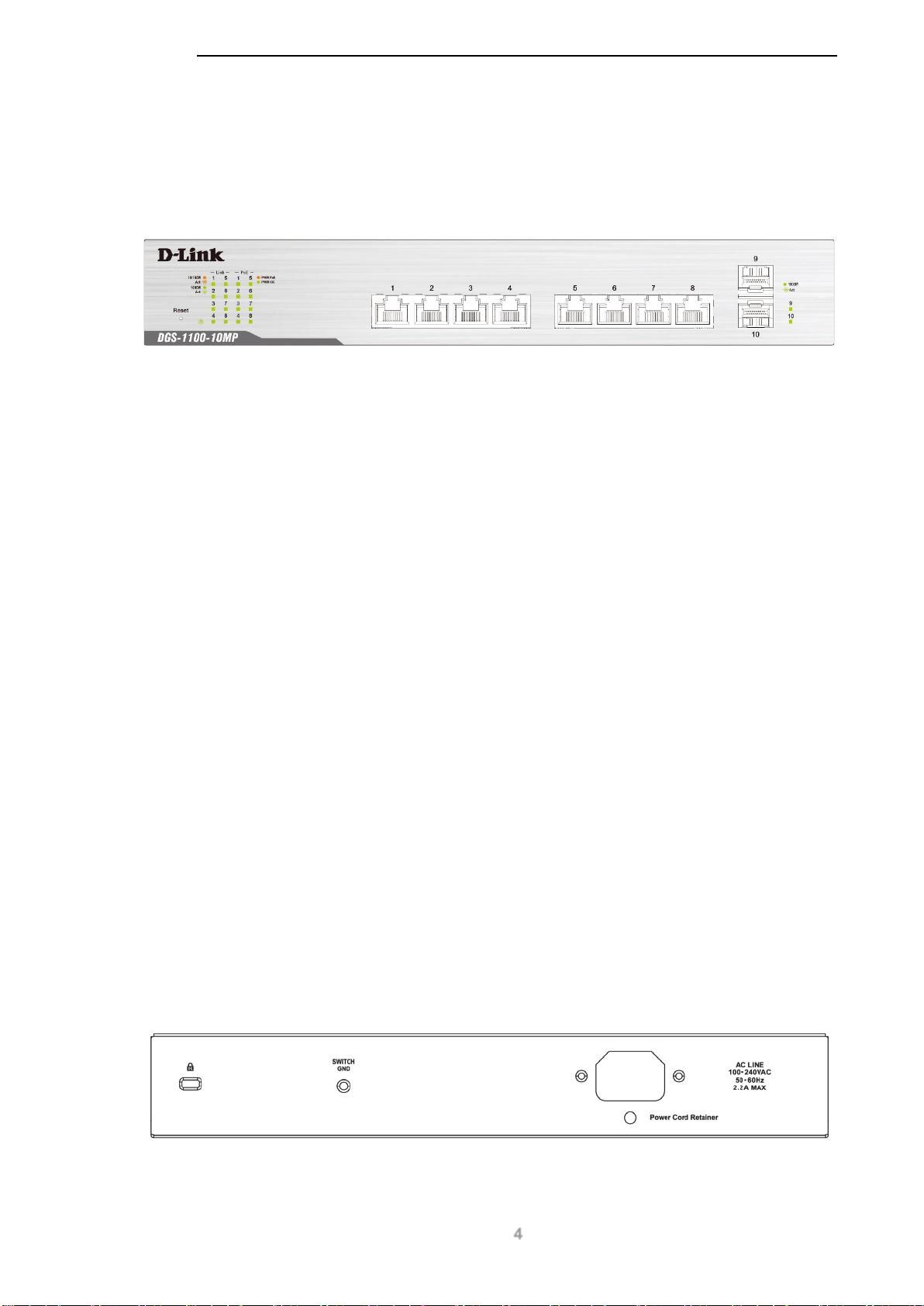
DGS-1100-10MP
8-Port 10/100/1000 Mbps + 2-Port SFP 10 00 Mbps Po E s witch
Front Panel
Figure 2-1 - DGS-1100-10MP Front Panel
Power LED: The Power LED lights up when the switch is connected to a power source.
Link/Act/Speed LED (Ports 1-8):
Solid Green: When there is a secure 1000Mbps connection at the port.
Blinking Green or Amber: Indicat es that th e switch is either sendi ng or rec eiving data to the
port.
Solid Amber: Indicates that the port is running at 10/100Mbps.
Light off: No link.
PoE Mode (Ports 1- 8):
Green: Indicates that PoE mode is active.
Amber: Indicates that there is an issue with the PoE mode activat ing pr op erly.
Light off: Indicates that PoE mode is not active.
Link/Act/Speed LED (Ports 9-10):
Solid Green: There is a secure 1000Mbps connection at the port.
Blinking Green: There is reception or transmission occurring at the port.
Light off: No link.
Reset: By pressing the Reset button until the power LED turns amber, the switch will change back to
the default configuration and all changes will be lost.
Rear Panel
Figure 2-2 – DGS-1100-10MP Rear Panel
4
Page 9

Power: The power port is where to connect the AC power cord.
CAUTION: The SFP ports should use UL listed Optical Transceiver product,
Rated Laser Class I. 3.3Vdc.
CAUTION: This equipment is to be connected only to PoE networks without
routing to the outside plant.
D-Link DGS-1100 MP/MPP Series Switch User Manual
5
Page 10
D-Link DGS-1100 MP/MPP Series Switch User Manual
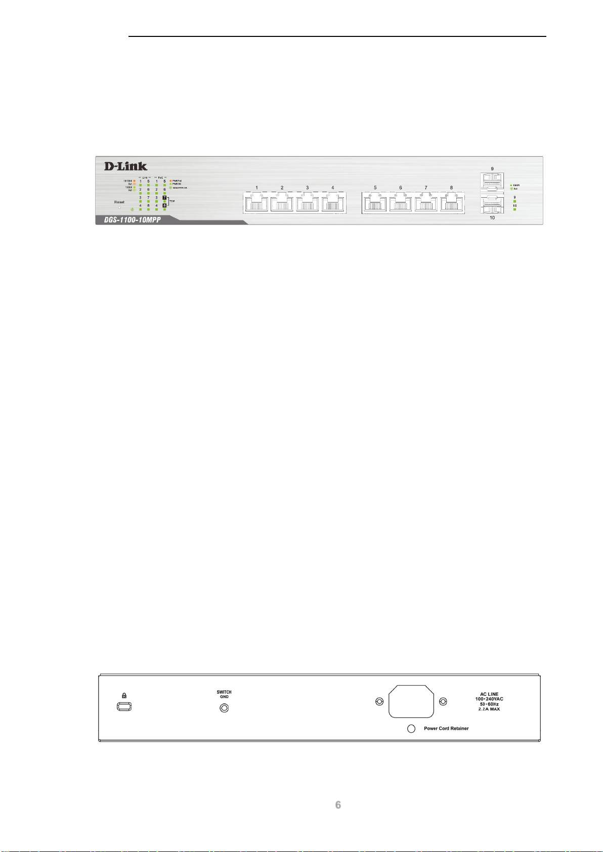
DGS-1100-10MPP
8-Port 10/100/1000 Mbps + 2-Port SFP 10 00 Mbps Po E switch
Front Panel
Figure 2-3 – DGS-1100-10MPP Front Panel
Power LED: The Power LED lights up when the switch is connected to a power source.
Link/Act/Speed LED (Ports 1-8):
Solid Green: When there is a secure 1000Mbps connection at the port.
Blinking Green or Amber: Indicat es that th e switch is either sendi ng or rec eiving data to the
port.
Solid Amber: Indicates that the port is running at 10/100Mbps.
Light off: No link.
PoE Mode (Ports 1- 8):
Green: Indicates that PoE mode is active.
Amber: Indicates that there is an issue with the PoE mode activating prop erly.
Light off: Indicates that PoE mode is not active.
Link/Act/Speed LED (Ports 9-10):
Solid Green: There is a secure 1000Mbps connection at the port.
Blinking Green: There is reception or transmission occurring at the port.
Light off: No link.
Reset: By pressing the Reset button until the power LED turns amber, the switch will change back to
the default configuration and all changes will be lost.
Rear Panel
Figure 2-4 – DGS-1100-10MPP Rear Panel
6
Page 11

Power: Connect the supplied AC power cable to this port.
CAUTION: The SFP ports should use UL listed Optical Transceiver product,
Rated Laser Class I. 3.3Vdc.
CAUTION: This equipment is to be connected only to PoE networks without
routing to the outside plant.
D-Link DGS-1100 MP/MPP Series Switch User Manual
7
Page 12

D-Link DGS-1100 MP/MPP Series Switch User Manual
DGS-1100-26MP
24-Port 10/100/1000 Mbps + 2-Port Combo 1000BASE-T/SFP PoE switch
Front Panel
Figure 2-5 – DGS-1100-26MP Front Panel
Power LED: The Power LED lights up when the switch is connected to a power source.
Link/Act/Speed LED (Ports 1-24):
Solid Green: When there is a secure 1000Mbps connection at the port.
Blinking Green or Amber: Indicat es that th e switch is either sendi ng or rec eiving data to the
port.
Solid Amber: Indicates that the port is running at 10/100Mbps.
Light off: No link.
PoE Mode (Ports 1- 24):
Green: Indicates that PoE mode is active.
Amber: Indicates that there is an issue with the PoE mode ac ti vat ing prop er ly.
Light off: Indicates that PoE mode is not active.
Link/Act/Speed LED (Ports 25-26):
Solid Green: There is a secure 1000Mbps connection at the port.
Blinking Green: There is reception or transmission occurring at the port.
Solid Amber: Indicates that the port is running at 10/100Mbps.
Light off: No link.
LED Mode Button: Pres sing this button will chan ge the LED behavior from Link mode, and Po E
Mode.
Reset: By pressing the Reset button until the power LED turns amber, the switch will change back to
the default configuration and all changes will be lost.
NOTE: The LED behavior for ports 1- 24 will switch between Link mode and PoE
mode when the PoE mode is active.
8
Page 13

D-Link DGS-1100 MP/MPP Series Switch User Manual
Rear Panel
Figure 2-6 – DGS-1100-26MP Rear Panel
Power: Connect the supplied AC power cable to this port.
CAUTION: The SFP ports should use UL listed Optical Transceiver product,
Rated Laser Class I. 3.3Vdc.
CAUTION: This equipment is to be connected only to PoE networks without
routing to the outside plant.
9
Page 14

D-Link DGS-1100 MP/MPP Series Switch User Manual
DGS-1100-26MPP
24-Port 10/100/1000 Mbps + 2-Port Combo 1000BASE-T/SFP PoE switch
Front Panel
Figure 2-7 – DGS-1100-26MPP Front Panel
Power LED: The Power LED lights up when the switch is connected to a power source.
Link/Act/Speed LED (Ports 1-24):
Solid Green: When there is a secure 1000Mbps connection at the port.
Blinking Green or Amber: Indicat es that th e switch is either sendi ng or rec eiving data to the
port.
Solid Amber: Indicates that the port is running at 10/100Mbps.
Light off: No link.
PoE Mode (Ports 1- 24):
Green: Indicates that PoE mode is active.
Amber: Indicates that there is an issue with the PoE mode activating properl y.
Light off: Indicates that PoE mode is not active.
Link/Act/Speed LED (Ports 25-26):
Solid Green: There is a secure 1000Mbps connection at the port.
Blinking Green: There is reception or transmission occurring at the port.
Solid Amber: Indicates that the port is running at 10/100Mbps.
Light off: No link.
LED Mode Button: Pres sing this button will chan ge the LED behavior from Link mode, and Po E
Mode.
Reset: By pressing the Reset button until the power LED turns amber, the switch will change back to
the default configuration and all changes will be lost.
NOTE: The LED behavior for ports 1- 24 will switch between Link mode and PoE
mode when the PoE mode is active.
10
Page 15
D-Link DGS-1100 MP/MPP Series Switch User Manual
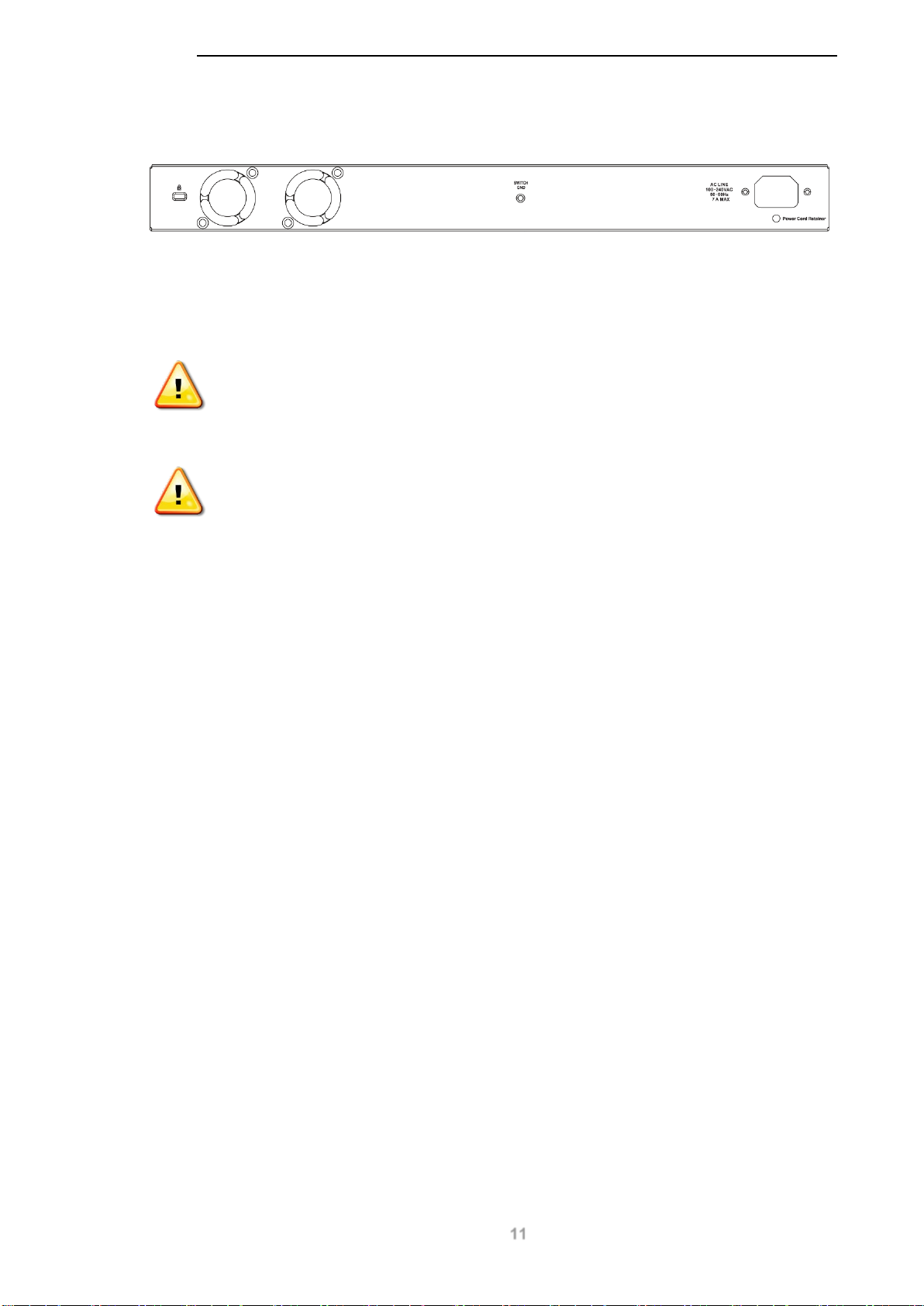
Rear Panel
Figure 2-8 – DGS-1100-26MPP Rear Panel
Power: Connect the supplied AC power cable to this port.
CAUTION: The SFP ports should use UL listed Optical Transceiver product,
Rated Laser Class I. 3.3Vdc.
CAUTION: This equipment is to be connected only to PoE networks without
routing to the outside plant.
11
Page 16
D-Link DGS-1100 MP/MPP Series Switch User Manual
3. Hardware Installation
This chapter provides unpacking and installation information for the D-Link switch.
Step 1: Unpacking
Open the shipping car ton and carefull y unpack its contents. Please co nsult the packing list located
below to mak e sur e all items are present and und amaged. If any item is missing or dam aged, p leas e
contact your local D-Link reseller for a replacement.
Packing Contents
• One D-Link DGS-1100 MP/MPP Series switch
• One AC power cord
• Four rubber feet
• Screws and two mounting brackets
• One accessory kit for a ground screw
• One Multi-lingual Getting Started Guide
• One CD with User Manual
Step 2: Switch Installation
For safe switch installation and operation, it is recommended that you:
• Visually inspect the power cord to see that it is secured fully to the AC power connector.
• Make sure that there is proper heat dissipation and adequate ventilation around the switch.
• Do not place heavy objects on the switch.
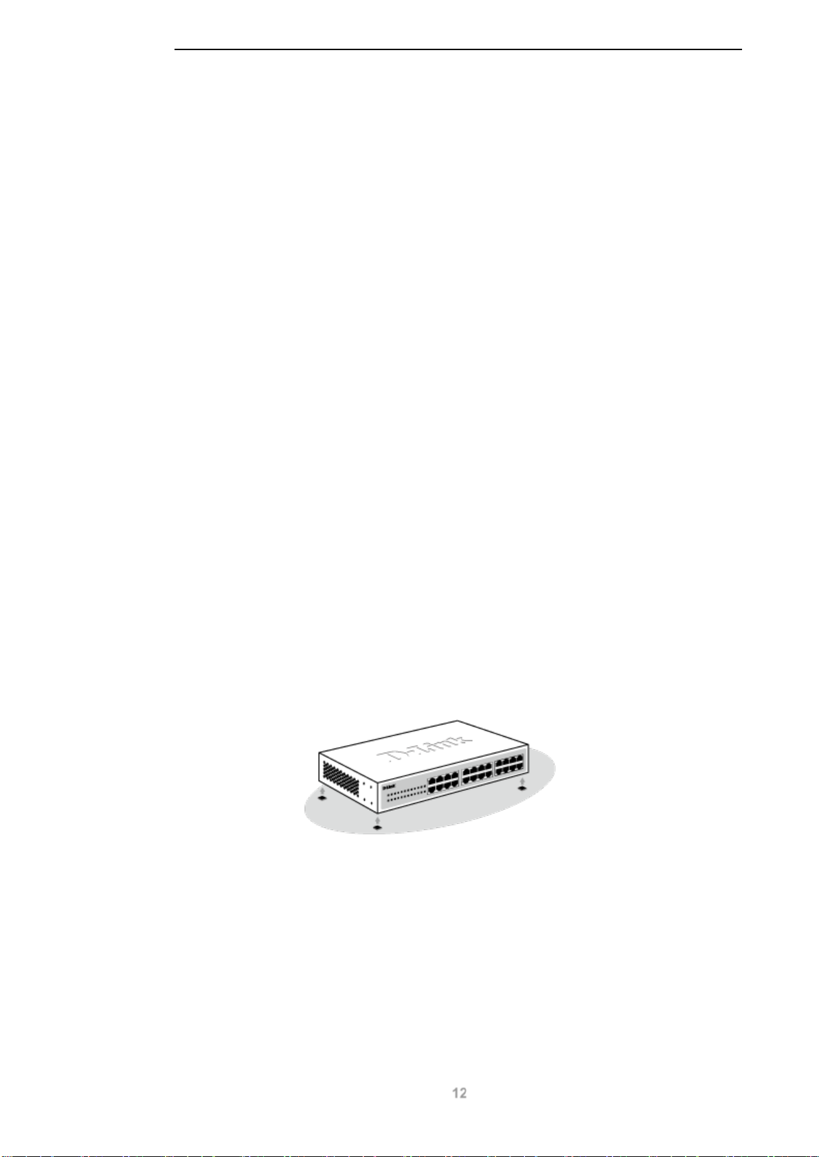
Desktop or Shelf Installation
When installing the switch on a desktop or shelf, the rubber feet include d with the device must be
attached on the bot tom at each corner of t he de vic e’s bas e. Al lo w e nou gh ve nt ila t ion s pace between
the device and the objects around it.
Figure 3-1 – Attach the adhesive rubber pads to the bottom
Rack Installation
The switch can be mounte d in an EIA standard size 19-inch r ack, which can be placed in a wiring
closet with other equ ipment.
12
Page 17
D-Link DGS-1100 MP/MPP Series Switch User Manual
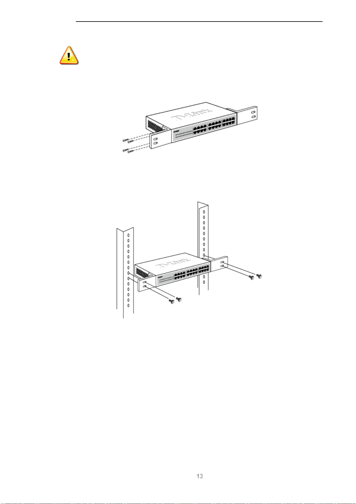
CAUTION: Ensure the power cable is disconnected before installing the switch.
To install, attach the m ounting brackets to the switch ’s side panels (one on each s ide) and secure
them with the screws provided.
Figure 3-2 – Attach the mounting brackets to the switch
Then, use the screws provided with the equipment rack to mount the switch in the rack.
Figure 3-3 – Mount the switch in the rack or chassis
Please be aware of following safety Instructions when installing:
A) Elevated Operati ng Ambient - If insta lled in a closed or multi-unit rack assembly, the operating
ambient temperature of the rack environment may be greater than room ambient. Therefore,
consideration should be given to installing the equipment in an environment compatible with the
maximum ambient temperature (Tma) specified by the manufacturer.
B) Reduced Air Flow - Installation of the equipm ent in a rack should be suc h that the am ount of air
flow required for safe operation of the equipment is not compromised.
C) Mechanical Lo ading - Mounting of the equipment in the rac k should be such that a hazardous
condition is not achieved due to uneven mechanical loading.
D) Circuit Overloadi ng - Considerati on should be given to the connect ion of the equipment to the
supply circuit and t he ef fec t that o verload ing of the c irc uits m ight ha ve on over current protec tion and
supply wiring. Appropriate consideration of equipment nameplate ratings should be used when
addressing this concern.
13
Page 18
D-Link DGS-1100 MP/MPP Series Switch User Manual
E) Reliable Earthing - Reliable ear thin g of rac k -mounte d equipm ent sho uld be m aintained . Par ticular
attention should be give n to supply connections other than d irect connections to the branch circu it
(e.g. use of power strips)."
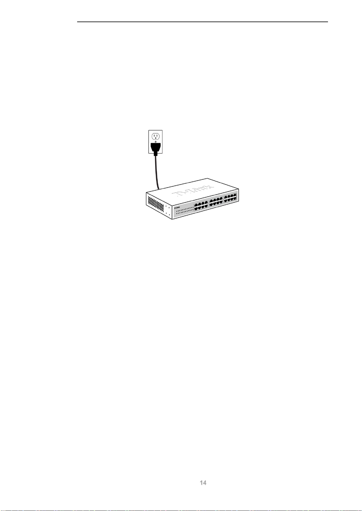
Step 3: Plugging in the AC Power Cord
Users may now connect the AC power cord into the rear of the switch and to an electrical outlet
(preferably one that is grounded and surge protected).
Figure 3-4 – Plugging the switch into an outlet
Power Failure
As a precaution, the switc h should be unplugg ed in case of power f ailure. When po wer is resumed,
the switch should be plugged back in.
Grounding the Switch
This section descr ibes how to connect the DGS-110 0 MP/MPP Series switch t o ground. You must
complete this procedure before powering your switch.
Required Tools and Equipment
• Ground screws (included in the accessory kit): One M4 x 6 mm (metric) pan-head screw
• Ground cable (not included in the accessory kit): The grounding cable should be sized
according to local and national installation requirements. Depending on the power supply
and system, a 12 to 6 AWG copper conductor is required for U.S installation. Commercially
available 6 AWG wire is recommended. The length of the cable depends on the proximity of
the switch to proper grounding facilities.
• A screwdriver (not included in the accessory kit)
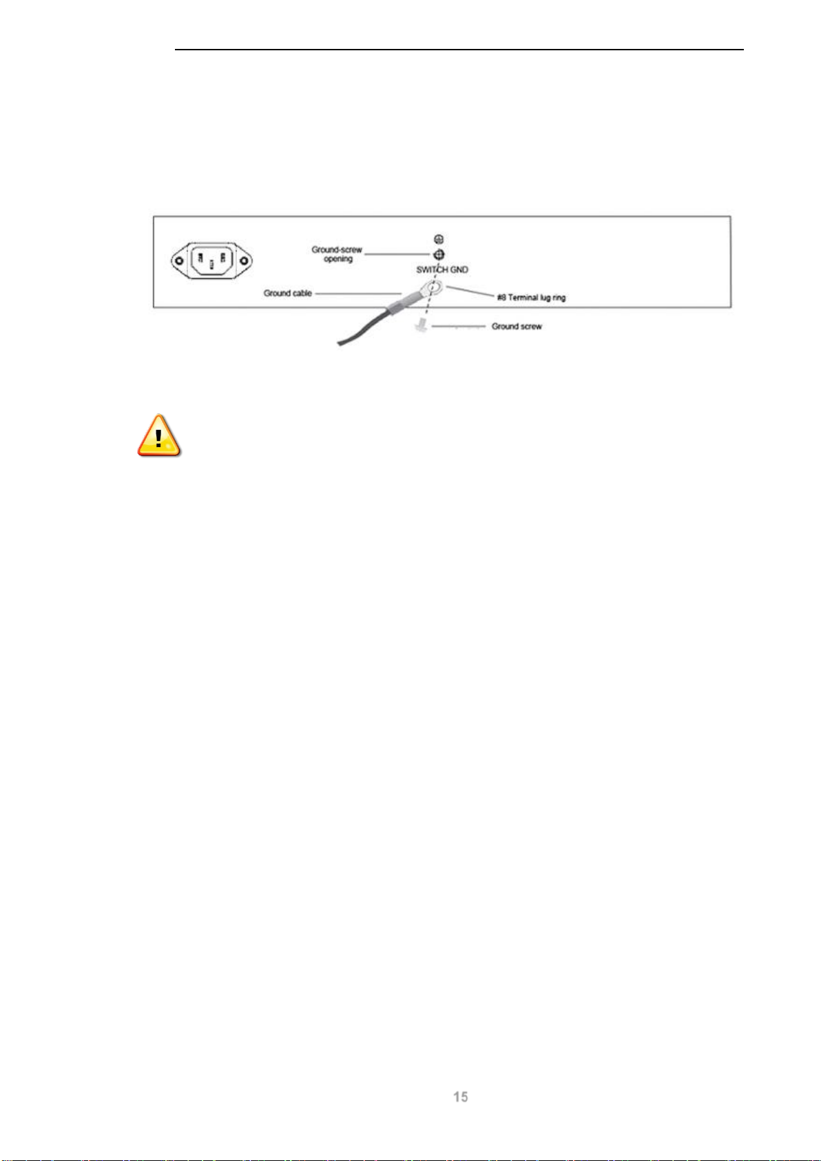
Follow these steps to ground the switch:
Step 1: Verify that the switch is not connected to a power supply.
Step 2: Use the ground c able to place the #8 t erminal lug ring on top of the ground-screw open ing,
as seen in the figure below.
Step 3: Insert the ground screw into the ground-screw opening.
Step 4: Using a screwdriver, tighten the ground screw to secure the ground cable to the switch.
14
Page 19
D-Link DGS-1100 MP/MPP Series Switch User Manual
Step 5: Attach the terminal lug ring at the other end of the grounding cable to an appropriate
grounding stud or bolt on rack where the switch is installed.
Step 6: Verify if th e connections at the ground connector on the switch and the rack are securely
attached.
Figure 3-5 – Ground cable, screw and #8 terminal lug rings
CAUTION: This equipment is to be connected only to PoE networks without
routing to the outside plant.
15
Page 20

D-Link DGS-1100 MP/MPP Series Switch User Manual
4. Web-based Switch Configuration
Management Options
Connecting using the Web User Interface
Logging onto the
Smart Wizard
Web User Interface
Management Options
The switch provides multiple access platform s that can be used to config ure, manage and monitor
networking features available on the switch. Currently there are three management platforms
available and they are described below.
Web-based Management Interface
After successfully installing the switch, the user can configure the switch, monitor the LED panel, and
display statistics graphically using a Web browser, such as Microsoft® Internet Explorer, Opera
Firefox, Safari, or Google Chrome.
SNMP-based Management
The switch can be managed with an SNMP-compatible console program. The switch supports
SNMP version 1.0, and version 2c. T he SNMP agent decodes the incom ing SNMP messages and
responds to requests with MIB objects stored in the database. T he SNMP agent updates the MIB
objects to generate statistics and counters.
D-Link Network Assistant
DNA (D-Link Network As sistant) included on the ins tallation CD is a pro gram for discovering DGS 1100 MP/MPP Series switches with the same L2 network segm ent connected to your PC. This tool
can support windows 2000, XP, Vista, and Windows 7.
Connecting using the Web User Interface
Most software functions of the DGS-1100 MP/MPP Series switches can be managed, configured
and monitored via the embedded web-based (HTML) interface. Manage the switch from remote
stations anywhere on the network through a standard web browser. The web browser acts as a
universal access tool and can communicate directly with the switch using the HTTP or HTTPS
protocol.
You need the following equipment to begin the web configuration of your device:
• A PC with a RJ-45 Ethernet connection
• A standard Ethernet cable
Figure 4-1 – Connecting to a DGS-1100 MP/MPP Series switch
16
Page 21

D-Link DGS-1100 MP/MPP Series Switch User Manual
Connect the Ethernet cab le to any of the ports on the f ront panel of the switch and to the E thernet
port on the PC.
Logging onto the Web User Interface
To access the W eb UI, simply open a web browser an d ent er the switch’s default IP address i nto t he
address bar. Make s ure that the IP ad dress of the m anagement PC is in the sam e subnet as the IP
address of the switch you are trying to connect to.
NOTE: The default IP address of the switch is 10.90.90.90, with a subnet mask
of 255.0.0.0.
NOTE: The default username is ‘admin’ and password is ‘admin’.
After successfully connecting to the Web UI, the Smart Wizard will be launched.
17
Page 22

D-Link DGS-1100 MP/MPP Series Switch User Manual
Smart Wizard
The Smart Wizard is a con figuration utilit y that is launched the first tim e the Web UI is acces sed. It
allows users to c onfigure bas ic settings s uch as the s witch m ode, managem ent IP and password. It
can also be used to switch between Standard Mode and Surveillance Mode Web UI types.
Step 1 – Web Mode
The initial pag e allows the user to choose bet ween Standard Mode and Surveilla nce Mode on the
switch. This can be changed at any time by returning to the Smart Wizard.
For more information on the Standard Mode features of the switch, please refer to the Standard
Mode Web UI Reference Guide.
Figure 4-2 Web Mode window
The fields that can be configured are described below:
Parameter Description
Web Mode Select the Surveillance Mode opti on to continue the Smart
Wizard in Surveillance Mode.
Please refer to the Stand ard Mode W eb UI Reference G uide
for more information on Standard Mode.
Tick the Ignore the wizard next time option to skip the Smart Wizard on the next login.
18
Page 23

D-Link DGS-1100 MP/MPP Series Switch User Manual
Click the Exit button to discard the changes made, exit the Smart Wizard, and continue to the
Standard Mode Web UI.
Click the Next button to accept the changes made and continue to the next step.
Step 2 – System IP Information
In this window, the user can configure the IP address assignm ent method, the static IP address,
netmask and gateway address.
NOTE: The s witch will probe IP-Cameras ever y 30 seconds. If an I P-Camera is
not in the same subne t as the switch, the IP-Camera will not be automatic ally
discovered. Place the switch management IP in the same subnet as the IPCameras for the cam eras to be automatically added to the Surveillance Mode
Web UI.
Figure 4-3 System IP Information window
19
Page 24

D-Link DGS-1100 MP/MPP Series Switch User Manual
The fields that can be configured are described below:
Parameter Description
Static
Select this option to m anually configure and use IP address
settings on this switch.
DHCP
Select this optio n to obt ain IP address settings f rom a DHCP
server.
IP Address
Netmask
Gateway
Enter the IP address of the switch here.
Select the netmask option here.
Enter the default gateway IP address here.
Tick the Ignore the wizard next time option to skip the Smart Wizard on the next login.
Click the Exit button to discard the changes made, exit the Smart Wizard, and continue to the
Standard Mode Web UI.
Click the Next button to accept the changes made and continue to the next step.
Step 3 – Admin Password
In this window, the user can set the password used with the admin account.
Figure 4-4 Admin Password window
Tick the Ignore the wizard next time option to skip the Smart Wizard on the next login.
20
Page 25

Click the Exit button to discard the changes made, exit the Smart Wizard, and continue to the
Standard Mode and Surveillance Mode Web UIs share the same
Settings are saved between interface types. It is possible to switch
Standard Mode Web UI.
Click the Apply & Save button to accept the changes made, and then continue to the Web UI.
NOTE:
configuration files. Any features en abled in one i nterface will be m ade available
in the other interface, for example: PoE scheduling, SNMP settings and the
surveillance VLAN in use.
NOTE:
interface types and re-run the Sm art W izard without lo sing settings saved in o ne
version of the interface.
D-Link DGS-1100 MP/MPP Series Switch User Manual
21
Page 26

D-Link DGS-1100 MP/MPP Series Switch User Manual
Web User Interface
When you complete the Surveillance Mode Smart Wizard you will be presente d with the following
screen:
Scroll to the bottom of the page and click the OK button to continue to the Web UI.
Figure 4-5 Congratulations window
22
Page 27

D-Link DGS-1100 MP/MPP Series Switch User Manual
Areas of the User Interface
The figure below shows the user int erfac e. T wo distinct areas d ivide the user interf ace, as described
in the table.
Figure 4-6 Main Web UI Window
Area Number Description
AREA 1
AREA 2
The navigation menu is displayed in this area. Click on the
links and navigate the f older structure to displa y information
on the main page.
This is the main page for displaying information and
configuration options f or the switch. T he page displayed here
is based on the selection in AREA 1 .
23
Page 28

D-Link DGS-1100 MP/MPP Series Switch User Manual
5. Surveillance Overview
This loads automatically when you log-in to the switch and contains two tabs; Surveillance
Topology and Device Infor mation. To retur n to the Surveillance Overview pa ge aft er viewing other
pages, click the model number of the switch at the top of the navigation menu.
Figure 5-1 Switch Model Number
Surveillance Topology
This is the default tab on the Survei llance O ver view page. It contains a diagram of the sur veill ance
topology, including an overview of the devices connected to the switch.
To view the following w indow, click on the model number of the switch at the t op of the navi gation
menu:
Figure 5-2 Surveillance Topology Window
There is a device count at the top of the page, listing the number of connected IP-Cameras,
Network Video Recor ders (NVRs) and unrecogn ized devices. It also lists the number of warnings
on the system.
24
Page 29

D-Link DGS-1100 MP/MPP Series Switch User Manual
The icon descriptions are as follows:
Icon Description
The total number of IP-Cameras detected.
The total number of NVRs detected.
The number of warnings on the system. Consult the Surveillance Log and
Health Diagnostic pages for more information.
The number of port s that have an unknown de vice connected that does n ot
support ONVIF.
The Surveillance Topology gives you more information about what is connected to each port.
Hover over each dev ice icon to get more infor mation about the recogni zed devices, such as: the
number of devices, de vice type, IP address, power c onsumption, link speed and er rors. Click on
the ‘more’ link to get mor e information about the devic es connected to a port. Each por t can also
be powered-on and off using PoE by clicking the power symbol on each port.
CAUTION: Before connecting the Powered Device (PD) and enabling 60/70 W
PoE, make sure it supports IEEE 802.3bt, as otherwise it will become damaged.
See below for more information on enabling and disabling PoE.
A breakdown of each device icon is below:
Icon Description
One ONVIF IP-Camera discovered on this port.
The link is up but no ONVI F IP-Camera or NVR has been disco vered on this
port.
Multiple ONVIF IP-Cameras discovered on this port.
One NVR discovered on this port. Any device fetching surveillance stream
from IP-Camera will be recognized as NVR.
Multiple NVRs discovered on this port.
One ONVIF IP-Camera and one NVR discovered on this port.
Multiple ONVIF IP-Cameras and one NVR discovered on this port.
25
Page 30

D-Link DGS-1100 MP/MPP Series Switch User Manual
One ONVIF IP-Camera and multiple NVRs discovered on this port.
This port is set as uplink port and it is link up.
This port is set as uplink port and it is link down.
NOTE: A breakdown of th e de v ic e icons c a n be f ound by clicking the H elp menu
at the top of the page.
NOTE: The system probes for new IP-Cameras every 30 seconds.
The icon border indicates the PoE status for the port:
Icon Border Description
The device is operational but not powered by PoE.
The device is operational and is powered by PoE.
The device has malfunctioned and there is a problem with
the port or device.
The port status indicators dictate the speed and status of the link:
Port Status Description
The link is down.
The port is connected at 1 Gbps.
The port is connected at 10/100 Mbps.
The PoE status is indicated by the power icon on each port:
Port Status Description
PoE is enabled on the port.
PoE is disabled on the port.
26
Page 31

D-Link DGS-1100 MP/MPP Series Switch User Manual
Enabling and Disabling PoE
CAUTION: Before connecting the Powered Device (PD) and enabling 60/70 W
PoE, make sure it supports IEEE 802.3bt, as otherwise it will become damaged.
The power status of each port can be changed by clicking the power ic on o n each port. The def aul t
setting for PoE is on. To chang e the PoE type, first disable PoE and then r e-enable it using the
type of PoE required.
The following dialogue box will be displayed when enabling PoE on a port:
Choose the type of PoE required. This can be either 15/30 W (60 W or 75 W is for MPP Series
only).
Click the Apply button to accept the changes made.
Figure 5-3 PoE Configuration
27
Page 32

D-Link DGS-1100 MP/MPP Series Switch User Manual
Device Information
This is the second tab on the Surveillance Overview page and is divided into 3 areas; a device
information section, PoE utilization section and bandwidth usage section.
To view the following window, click on the m odel number of the switch at the top of the navigation
menu and the click the Device Information tab:
Figure 5-4 Device Information Window
The device inform ation section is sub-divided into 3 sections; switch information, web information
and system information. It contains information such as the device type, system name, serial number,
IP address settings, MAC address settings, firmware versions and system uptime.
The PoE utilizatio n area co ntains PoE u tilization stat istics f or the switch . On the left is the total PoE
utilization, with the tot al power bud get and overall ut ilization sh own. On the righ t is a per-port us age
graph, showing the PoE utilization for each individual port.
The bandwidth usage section contains bandwidth utilization for the switch. On the left the total
bandwidth shows the t otal inbound traffic on all ports. There is also a per -port bandwidth utilizatio n
graph on the right, s ho win g the inbound traff ic for each ind iv idual por t. The scale of t he graph c an be
changed by pressing the 1000 Mbps and 50 Mbps buttons above the graph.
28
Page 33

6. Port Information
The Port Information sec tion provides an ov erview of the port status for each port . This includes the
throughput, PoE status, Loopback Detection Status, cable length, power consumption and the
devices connected to each port.
To view the following window, click on the Port Information link in the navigation menu:
D-Link DGS-1100 MP/MPP Series Switch User Manual
A breakdown of the dev ices connected, the number of ports in use and t he total throug hput is listed
at the top of the page. The icon descriptions are as follows:
Icon Description
The total amount of ports that are currently active.
The total inbound throughput for all ports on the switch.
The total number of ONVIF IP-Cameras detected.
The total number of NVRs detected.
The number of ports that have a n unknown device connected that d oes not
support ONVIF.
Figure 6-1 Port Information Window
29
Page 34

D-Link DGS-1100 MP/MPP Series Switch User Manual
consumed by the port. The positive integer is the PoE budget for PoE
Hover-over each field to get more information about each value. A breakdown of each field is below:
Icon Description
The port number of the port.
The total inbound throughput for the port on the switch (measured in Mbps).
The cable length (in meters), taken from the Health Diagnostics page.
The PoE status for the port (PoE on or off).
The PoE consum ption of the port. This is l isted as one negative i nteger and
one positive integer. A negative value for PoE means that power is being
standard in use.
The Loopback Detectio n status. If a loo p is detected, the icon will ch ange to
include a link to the H e alt h Diag nos tics page.
The G roup Details page. If an ONVIF device is det ected as being con nected
to the port, the icon c hanges to inc lude a link to the Group De tails page. If a
device is connected tha t is not ONVIF com patible, a dr op-down menu wil l be
available to define the type of device connected.
30
Page 35

D-Link DGS-1100 MP/MPP Series Switch User Manual
with NVR1 having Group Number 1. If an NVR is removed, the Group
Numbers will be updated accordingly (if NVR1 is removed then Group
Group Details
The Group Details page lists the devices connec ted to a specif ic port. Only d evices that ha ve been
recognized as supporting ONVIF or NVRs will be displayed.
To view the followin g window, click on the Port Information link in the na vigation menu and then
click on the Group Details link for a port that has recognized devices connected to it:
Figure 6-2 Group Details Window
The port number that the Group Details apply to is listed at the top of the page. The icon descriptions
are as follows:
Icon Description
The port number that the Group Details apply to.
Click to go back to the Port Information page.
Hover-over each field to get more information about each value. A breakdown of each field is below:
Icon Description
The Group Number that the de vice belongs to. All devices managed by an
NVR belong to the s ame Group Number. Thes e are assigned sequentiall y,
Number 2 will become Group Number 1).
The device type. This can be an IP-Camera or NVR.
The Model name of the IP-Camera. Nothing is displayed in this field if an
NVR is connected.
The IP address of the IP-Camera or NVR.
31
Page 36

The device description. This can be edited on the IP-Camera Information
page or NVR Information page.
D-Link DGS-1100 MP/MPP Series Switch User Manual
32
Page 37

D-Link DGS-1100 MP/MPP Series Switch User Manual
7. IP-Camera Information
The IP-C amera Inform ation section prov ides inform ation on each cam era connected t o the switch.
It features the port num ber , device t ype, thr oug hput, IP address and ot her inf orm ation suc h as por t
description, power consumption and location.
To view the following window, click on the IP-Camera Information link in the navigation menu:
Figure 7-1 Port Information Window
The total device count, thr o ughp ut an d po w er c ons um ptio n is listed at the top of the page. The icon
descriptions are as follows:
Icon Description
The total number of ONVIF IP-Cameras detected.
The total inbound throughput for all ports on the switch.
The PoE consumption of the switch. This is listed as one negative integer
and one positive int eger. The neg ative integer is the power be ing consumed
by the PoE devices conne cted to the switch. The positi ve integer is the total
PoE budget for the ports currently using PoE, based on the t ype of PoE in
use.
Hover-over each field to get more information about each value. A breakdown of each field is
below:
Icon Description
The port number of the port.
The device icon or photo. A generic photo will displayed for a non-D-Link
ONVIF c amera. A D-Link-specific photo will be displa yed for a D-Link ONVIF
camera.
33
Page 38

The total inbound throughput for the port on the switch (measured in Mbps).
consumed by the port. The positive integer is the PoE budget for PoE
The PoE consum ption of the port. This is list ed as one negative integ er and
one positive integer. A negative value for PoE means that power is being
standard in use.
The IP address of the IP-Camera.
The location of the IP-Camera.
The description of the I P-Camera. This can be edited by click ing the black
pencil icon next to the field ( ) and then the green pencil icon when the
description has been entered ( ).
D-Link DGS-1100 MP/MPP Series Switch User Manual
34
Page 39

8. NVR Information
) and then the green pencil icon when the
NVR belong to the same Group Number. These are as signed sequentially,
The NVR Information section provides information on each NVR connected to the switch. It
features the port number, throughput, IP address and information relating to the cameras
connected to the NVR, such as the group name, total number of cameras and the port and IP
address of each camera. Hover-over each field to get more information about each value.
To view the following window, click on the NVR Information link in the navigation menu:
D-Link DGS-1100 MP/MPP Series Switch User Manual
Figure 8-1 NVR Information Window
The total number of NVRs and the total throughput is listed at the top of the page. The icon
descriptions are as follows:
Icon Description
The total number of NVRs detected.
The total inbound throughput for all ports on the switch.
Hover-over each field to get more information about each value. A breakdown of each field is
below:
Icon Description
The port number of the port.
The device icon or photo. A generic photo is displayed for all NVR types.
The total inbound throughput for the port on the switch (measured in Mbps).
The IP address of the NVR.
The Descr iption of the NVR. This can be edi ted by clicking the black pencil
icon next to the field (
description has been entered ( ).
The Group Number that a device belongs to. All devices managed by an
35
Page 40

with NVR1 having Group Number 1. If an NVR is removed, the Group
Numbers will be updated accordingly (if NVR1 is removed then Group
Number 2 will become Group Number 1).
The number of ONVIF IP-Cameras managed by this NVR.
Information relating t o an IP-Camera in th e group, such as port num ber and
IP address.
D-Link DGS-1100 MP/MPP Series Switch User Manual
36
Page 41

9. PoE Information
The PoE Information section pr o vides inf or mation on the PoE us age of eac h p ort. The port num ber ,
PoE status , health status, Po E budget an d power c onsum ption is listed f or each port. It is possible
to click on the health status to be re-directed to the Healt h Diagnostic page. Hover -over each fie ld
to get more information about each value.
To view the following window, click on the PoE Information link in the navigation menu:
D-Link DGS-1100 MP/MPP Series Switch User Manual
Figure 9-1 PoE Information Window
The total power bu dget, power consum ption, power budget c onsumption and the t ypes of PoE in
use are listed at the top of the page. The icon descriptions are as follows:
Icon Description
The total PoE power budget.
The PoE consum ption of the switch. This is listed as one negative integer
and one positive integer. The negative integer is the power being consum ed
by the PoE devices c onnected to the s witch. The pos itive integer is the total
PoE budget for the ports currently using Po E, based on the type of PoE in
use.
The current utilization of PoE power budget.
The number of 15 W PoE devices discovered.
The number of 30 W PoE devices discovered.
The number of 60/70 W PoE devices discovered.
37
Page 42

D-Link DGS-1100 MP/MPP Series Switch User Manual
The maximum PoE power budget for this port. This can be 30 W, or
state. If any fault is detected the icon changes to include a
consumed by the port. The positive integer is the PoE budget for PoE
Hover-over each field to get more information about each value. A breakdown of each field is
below:
Icon Description
The port number of the port.
The PoE status for the port (PoE on or off).
30W/60W /75W if this port supports 4-pair PoE.
The PoE
description of the problem and a link to the Health Diagnostic page.
The PoE consumptio n of the port. This is listed as one negative integ er and
one positive integer. A negative value for PoE means that power is being
standard in use.
38
Page 43

10. PoE Scheduling
PoE Scheduling is a f eatur e whic h allows you to specify the am ount of tim e that po wer is del ivered
to a PoE port. This can be used to save power when devices are not in use, or as a security
feature to prevent wireless access from being available outside of business hours, for example. It is
possible to set a schedule name, a start time, an end time and which ports the PoE schedule
applies to.
To view the following window, click on the PoE Scheduling link in the navigation menu:
D-Link DGS-1100 MP/MPP Series Switch User Manual
Figure 10-1 PoE Scheduling Window
The fields that can be configured for the Time Profile are described below:
Parameter Description
Range Name
Daily
From Time (Day/Hour) The start da y and time for the PoE sc hedule. Click the calendar
To Time (Day/Hour) The end da y and time for the PoE schedule. Click the calendar
Click the Apply button to accept the changes made.
The fields that can be configured for the PoE Configuration are described below:
Parameter Description
Enter a descriptive name for the PoE schedule.
Check this tick-box to enab l e the s c hed ule da il y and gray-out the
day-of-week fields in the From Time/To Time sections.
icon to pick this using a graphic calendar tool.
icon to pick this using a graphic calendar tool.
From Port The start port in the range that the PoE sc hed ule will appl y to.
To Port The end port in the range that the PoE schedule will apply to.
39
Page 44

D-Link DGS-1100 MP/MPP Series Switch User Manual
Time Profile
Click the Apply button to accept the changes made.
The Time Profile created above.
40
Page 45

11. Time
System Time
Clock Settings
SNTP Settings
Clock Settings
This sub-menu is used to configure the time on the switch.
To view the following window, go to: Time > Clock Settings in the navigation menu:
D-Link DGS-1100 MP/MPP Series Switch User Manual
Figure 11-1 Clock Settings Window
The fields that can be configured for the Clock Settings are described below:
Parameter Description
Use this to set the system time in the format (HH:MM:SS).
(HH:MM:SS)
Date (DD / MM / YYYY)
Click the Apply button to accept the changes made.
Use this to set the date, in the format (DD / MM / YYYY).
SNTP Settings
This sub-menu is us ed to configure an externa l time source on the switc h. Simple Network Tim e
Protocol (SNT P) is a lightweig ht version of the N TP protocol and can be used to k eep the system
clock in-s ync by using a networ k-based time source.
To view the following window, go to: Time > SNTP Settings in the navigation menu:
The fields that can be configured for the SNTP Global Settings are described below:
Parameter Description
Current Time Source
Figure 11-2 SNTP Settings Window
Displays the current time source for the switch.
41
Page 46

D-Link DGS-1100 MP/MPP Series Switch User Manual
SNTP State Set the SNTP state. Options are Enabled or Disabled.
Pool Interval (30-99999)
Click the Apply button to accept the changes made.
The fields that can be configured for the SNTP Server Setting are described below:
Parameter Description
IPv4 Address
Click the Apply button to accept the changes made.
Set the synchronizatio n interval for SNTP. The default is 720
seconds and the range is 30 – 99999 seconds.
Enter the IP address of the SNTP server you would like to
synchronize with.
42
Page 47

D-Link DGS-1100 MP/MPP Series Switch User Manual
12. Surveillance Settings
The Surveil lance Setti ngs page is used t o configure the settings for the S urveillan ce VLAN. T his is
a VLAN dedicated for IP-C amera and survei llance traffic and can be use d to manage sur veillance
devices on the network.
To view the following window, click on the Surveillance Settings link in the navigation menu:
Figure 12-1 Surveillance Settings Window
The fields that can be configured for the Surveillance VLAN Settings are described below:
Parameter Description
VLAN ID (2-4094)
Click the Apply button to accept the changes made.
The fields that can be configured for the IP Settings are described below:
Parameter Description
Get IP From
IP Address
Enter a VLAN number for the surveillance VLAN in the range
(2-4094).
Choose how the managem ent IP for this VLAN is assigned to
the switch. Options are: DHCP, Static or BOOTP. If Static is
chosen, the following fields become available:
Enter the IP address f or the surveillance VLAN management
IP.
Mask
Gateway
Click the Apply button to accept the changes made.
Enter the netmask for the surveillance VLAN management IP.
Enter the gateway for the surveillance VLAN.
43
Page 48

D-Link DGS-1100 MP/MPP Series Switch User Manual
Enter the IP address of the SNMP Network Management
used for connecting the surveillance VLAN with other
used for connecting the surveillance VLAN with other
The fields that can be configured for the SNMP Host Settings are described below:
Parameter Description
Host IPv4 Address
Server (NMS) which will receive SNMP Traps from this device.
Click the Apply button to accept the changes made.
The fields that can be configured for the Log Server are described below:
Parameter Description
Host IPv4 Address
Enter the IP address of the Syslog NMS which will receive
Syslog messages from this device.
Click the Apply button to accept the changes made.
The fields that can be configured for the Password Settings are described below:
Parameter Description
Password
Configure the passwor d that will be used to restrict ac cess to
the device via the W eb UI. Password le ngth is a maximum of
20 characters.
Confirm Password
Confirm the password th at wil l be used t o res tr ict ac c e ss to the
device via the W eb UI. Password len gth is a maximum of 20
characters.
Click the Apply button to accept the changes made.
The fields that can be configured for the Uplink Port Settings are described below:
Parameter Description
From Port Enter the start port in the range for Uplink Ports. These are
switches.
To Port Enter the end port in the range for Uplink Ports. These are
switches.
Click the Apply button to accept the changes made.
Click the Delete button to delete any entries in the list of uplink ports.
44
Page 49

D-Link DGS-1100 MP/MPP Series Switch User Manual
NOTE: It is highly recommended that only uplink ports are connected to other
10MP/10MPP are port9 and
switches, as the IP-Camera d iscovery process is dis abled on these ports. Use the
Uplink Port Settings section of the interface to d efine whic h ports c onnect to ot her
switches.
NOTE: The default uplink ports of the DGS-1100port10. The default uplink ports of DGS-1100-26MP/26MPP are port25 and port26.
45
Page 50

13. Surveillance Log
The Surveillance L og consists of a list of Syslog m es sages th at h ave been generated b y the s witc h.
Depending on whether a Syslog server has been defined in the Surveillance Settings section,
these may be local to the switch or copied to an external logging server. The messages are
ordered in date order with the latest message at the top of the list. Please consult an external
source for more information on Syslog logging levels.
To view the following window, click on the Surveillance Log link in the navigation menu:
D-Link DGS-1100 MP/MPP Series Switch User Manual
Refresh: This will refresh the page.
Backup: This will allow you to save a local copy of the Syslog messages as a text file.
Enter a page num ber and click the Go button to navi gate to a specific p age when multiple pages
exist.
Figure 13-1 Surveillance Log Window
46
Page 51

14. Health Diagnostic
The Health Diagnostic page is link ed-to by the Port Information and PoE Inf ormation pages and
displays an overvie w of the port status. It contains the port number, Loopbac k Detection status,
Cable Link status, PoE St atus, Tx/Rx Err or Counter, number of Discovered Surveillance Devices
on the port (which links to the Group Details page) and the detected cable length. The page
automatically refreshes every 30 seconds.
To view the following window, click on the Health Diagnostic link in the navigation menu:
D-Link DGS-1100 MP/MPP Series Switch User Manual
Figure 14-1 Health Diagnostic Window
Detect: Detect the cable length of the listed port.
Detect All: Detect the cable length of all ports.
47
Page 52

15. Save and Tools
Firmware Information
Firmware Upgrade & Backup
Configuration Restore & Backup
Reset
Reboot System
Firmware Information
This window is used to show firmware information.
To view the following window, click Tools > Firmware Information, as shown below:
D-Link DGS-1100 MP/MPP Series Switch User Manual
Figure 15-1 Firmware Information window
Boot Up: Clicking the Boo t Up button will set that fir mware im age as the active image to use upon
the next system start up.
NOTE: Changing the f irmware only happens after the switch has been manually rebooted. In order
to boot with the newly selected firmware, make sure that the switch is rebooted.
Firmware Upgrade & Backup
NOTE: W hen upgrading the f irmware on the DGS-1100 MP/MPP Series s witch, only
the image not currently active can be upgraded. All DGS-1100 MP/MPP Series
switches come with t wo images, however only one ca n be active at any time. (e.g. If
Firmware Upgrade from HTTP
This window is used to initiate a firmware upgrade from a local PC using HTTP.
To view the following window, click Tools > Firmwar e Upgrade & Backup > Firmw are Upgrade
from HTTP, as shown below:
image 1 is currently in use, only image 2 can be upgraded, and vice versa.)
NOTE: If the switch is in HTTPS mode, the firmware or configuration cannot be
upgraded using regular HTT P.
Figure 15-2 Firmware Upgrade from HTTP window
The fields that can be configured are described below:
48
Page 53

D-Link DGS-1100 MP/MPP Series Switch User Manual
Enter the source filename and path of the firmware file
Parameter Description
Source File
located on the local PC. Alternatively click the Browse
button to navigate to the loc ation of the firmware file loc ated
on the local PC.
Click the Upgrade button to initiate the firmware upgrade.
Firmware Backup to HTTP
This window is used to initiate a firmware backup to a local PC using HTTP.
To view the following window, click Tools > Firmw are Upgrade & Backup > Fi rmware Backup to
HTTP, as shown below:
Figure 15-3 Firmware Backup to HTTP window
The fields that can be configured are described below:
Parameter Description
Source
Click the Backup button to initiate the firmware backup.
Select the source image to use for the firmware backup.
49
Page 54

D-Link DGS-1100 MP/MPP Series Switch User Manual
Configuration Restore & Backup
Configuration Restore from HTTP
This window is used to initiate a configuration restore from a local PC using HTTP.
NOTE: If the switch is in HTTPS mode, the firmware or configuration cannot be upgraded using
regular HTTP.
To view the followin g window, click Tools > Configuration Restore & Backup > Configuration
Restore from HTTP, as shown below:
Figure 15-4 Configuration Restore from HTTP window
The fields that can be configured are described below:
Parameter Description
Source File
Click the Restore button to initiate the configuration restore.
Click Effective immediately (running-config) to have the uploaded configuration loaded
immediately.
Click Take effect after the next boot (startup-config) to load the configur a tio n a f ter the switch has
been rebooted.
Enter the source filenam e and path of the configuration file
located on the local PC. Alternatively click the Browse button
to navigate to th e location of the conf iguration file located on
the local PC.
Configuration Backup to HTTP
This window is used to initiate a configuration file backup to a local PC using HTTP.
To view the followin g window, click Tools > Configuration Restore & Backup > Configuration
Backup to HTTP, as shown below:
Figure 15-5 Configuration Backup to HTTP window
Select Include username password to save the switch user accounts and passwords to the backup
file.
Select Exclude username password to save the switch user accounts and passwords to the
backup file.
Click the Backup button to initiate the configuration file backup.
50
Page 55

D-Link DGS-1100 MP/MPP Series Switch User Manual
Reset
This window is used to reset the switch’s configuration to the factory default settings.
To view the following window, click Tools > Reset, as shown below:
Figure 15-6 Reset window
Select the The Switch will be reset to its factory defaults including IP address and stacking
information, and the will save, reboot option to reset the switch’s configuration to its factory
default settings.
Select the The Switch will be reset to its factory default except IP address, and then will save,
reboot option to reset the switch’s configuration to its factory default settings. This option will
exclude the IP address from being changed.
Select the The Switch will be reset to its factory defaults including IP address option to res et
the switch’s configuration to its factory default settings.
Click the Apply button to initiate the factory default reset and reboot the switch.
NOTE: Performing a factory reset in one version of the interface (Standard Mode
or Surveillance Mode) will cause settings to be reset in the other ver sion of the
interface.
Reboot System
This window is used to reboot the switch and alter n ati vel y sa ve the c o nf igur at io n bef or e do ing so . To
view the following window, click Tools > Reboot System, as shown below:
Figure 15-7 Reboot System window
When rebooting the switch, any configuration changes that was made during this session, will be lost
unless the Yes option is selected when asked to save the settings.
Click the Reboot button to alternatively save the settings and reboot the switch.
51
Page 56

D-Link DGS-1100 MP/MPP Series Switch User Manual
Figure 15-8 Reboot System - Rebooting window
52
Page 57

D-Link DGS-1100 MP/MPP Series Switch User Manual
16. Appendix A - Ethernet Technology
This chapter will d escribe the features of the D-Link DGS-1100 MP/MPP Series switch and provide
some background information about Ethernet/Fast Ethernet/Gigabit Ethernet swit ching tec hn olo g y.
Gigabit Ethernet Technology
Gigabit Ethernet is a n extension of IEE E 802.3 Ethernet u tilizing the sam e packet structure, f ormat,
and support for CSMA/CD pr otoc ol , f ull duplex, and management objects, but with a t enf ol d inc r ease
in theoretical throughpu t of over 100-Mbps F ast Ethernet and a hundre dfold increase over 10-Mbps
Ethernet. Since it is compatible with all 10-Mbps and 100-Mbps Ethernet environments, Gigabit
Ethernet provides a straightforward upgrade without wasting existing investments in hardware,
software, or trained personnel.
The increased speed and extra bandwidth offered by Giga bit Ethernet is essential to help solv ing
network bottlenecks that frequently develop as more advanced computer users and newer
applications continue to demand greater network resources. Upgrading key com ponents, such as
backbone connections and servers to Gigabit Ethernet technology can greatly improve network
response times as well as significantly speed up the traffic between subnets.
Gigabit Ethernet enables fast optical fiber connections to support video conferencing, complex
imaging, and similar da ta-intensi ve applica tions. L ikewise, s ince data tr ansfers occur 10 tim es faster
than Fast Ethernet, s ervers outfitted with Gigabit Ethernet NI C’s are able to perform 10 times the
number of operations in the same amount of time.
In addition, the phenomenal bandwidth delivered by Gigabit Ethernet is the most cost-effective
method to take advantage of today and tomorrow’s rapidly improving switching and routing
internetworking techn ologie s. And with expecte d adva nces in the com ing years i n silicon tec hnolog y
and digital signal proc essing that will enab le Gigabit Ethernet to e ventually opera te over unshielded
twisted-pair (UTP) cabling, outfitting your network with a powerful 1000-Mbps-capable
backbone/server connection which will creat e a flexible found ati on f or th e n ex t ge ner ati on of net wor k
technology products.
Fast Ethernet Technology
The growing importance of LANs and the increasing complexit y of desktop computing applications
are fueling the need f or high performance networks. A number of high-speed LAN tec hnolog ies have
been proposed to provide greater bandwidth and improve client/server response times. Among
them, 100BASE-T (Fast Ethernet) provides a non-disruptive, smooth evolution from the current
10BASE-T technology. The non-disruptive and smooth evolution nature, and the dominating
potential market base, virtually guarantees cost-effective and high performance Fast Ethernet
solutions.
100Mbps Fast Ether net is a s tandard spec ifie d b y the IEEE 8 02.3 L AN c omm ittee. It is an ex tens ion
of the 10Mbps Ethernet standard with the ability to transmit and receive data at 100Mbps, while
maintaining the C SM A/CD Ethernet protocol. Si nc e t h e 10 0M bps Fas t Eth er net i s com pat ible wit h all
other 10Mbps Ethernet environments, it provides a straightforward upgrade and utilizes existing
investments in hardware, software, and personnel training.
Switching Technology
Another approach to push beyond the l imits of Ethernet tec hnology is the development of switching
technology. A s witch bridges Ethernet packets at the MAC address level of the Ethernet protocol
transmitting among connected Ethernet or Fast Ethernet LAN segments.
Switching is a cost-effective way of increas ing the t o ta l net wor k c apac it y availa ble to user s on a loca l
area network. A switch inc reases capacity and decreases network loading by dividing a local ar ea
53
Page 58

D-Link DGS-1100 MP/MPP Series Switch User Manual
network into different segments which won’t compete with each other for network transmission
capacity.
The switch acts as a high-speed selective bridge between the individual segments. The switch,
without interfering with any other s egments, automaticall y forwards traff ic that needs to go from one
segment to another. B y doing this the total network capacity is multiplie d, while still maintainin g the
same network cabling and adapter cards.
54
Page 59

D-Link DGS-1100 MP/MPP Series Switch User Manual
17. Appendix B - Technical Specifications
Hardware Specifications
Key Components / Performance
Switching Capacity:
- DGS-1100-10MP: 20Gbps
- DGS-1100-10MPP: 20Gbps
- DGS-1100-26MP: 52Gbps
- DGS-1100-26MPP: 52Gbps
Max. Forwarding Rate:
- DGS-1100-10MP: 14.88Mpps
- DGS-1100-10MPP: 14.88Mpps
- DGS-1100-26MP: 38.69Gbps
- DGS-1100-26MPP: 38.69Gbps
Forwarding Mode: Store and Forward
Packet Buffer memory:
- DGS-1100-10MP: 1.5Mb ytes
- DGS-1100-10MPP: 1.5Mbytes
- DGS-1100-26MP: 1.5Mb ytes
- DGS-1100-26MPP: 1.5Mbytes
Flash Memory: 16M Byte
Port Functions
Physical & Environment
Power input: 100~240 VAC, 50/60Hz,
internal universal power supply
Acoustic Value:
- DGS-1100-10MP: 45.4dB
- DGS-1100-10MPP: 53dB
- DGS-1100-26MP: 56dB
- DGS-1100-26MPP: 56dB
Operation Temperature: -5-50°C
Storage Temperature: -40-70°C
Operation Humidity: 0% ~ 95% RH
Storage Humidity: 0% ~ 95% RH
Emission (EMI) Certifications
FCC class A
CE Class A
VCCI Class A
BSMI
CCC
Safety Certifications
CUL, LVD, CB, CCC, BSMI
10/100/1000BaseTX ports compliant wit h
the following standards:
- IEEE 802.3
- IEEE 802.3u
- IEEE 802.3ab
- IEEE 802.3at
- IEEE 802.3af
- IEEE 802.3bt (DGS-1100 MPP Series
only)
- Supports Full/half-Duplex operations at
10/100Mbps
- Supports Full-Duplex operation at
1000Mbps
- Supports IEEE 802.3x Flow Control
- Support Auto-Negotiation
- Compliant to IEEE 802.3az Energy
Efficiency Ethernet.
SFP ports compliant with the following
standards:
- IEEE 802.3z compliance
Features
L2 Features
16K MAC address
Loopback Detection
Port Mirroring
Link Aggregation
Cable Diagnostics
Spanning Tree
Ethernet Ring Protection Switching
(ERPS)
L2 Multicasting
IGMP Snooping
VLAN
802.1Q VLAN standard
Port-Based VLAN
Surveillance VLAN
Voice VLAN
55
Page 60

Asymmetric VLAN
Quality of Service (QoS)
802.1p priority
4 queues
Bandwidth Control
Security
Storm Control
DoS Attack Prevention
SSL
D-Link Safeguard
DHCP Snooping
Management
D-Link DGS-1100 MP/MPP Series Switch User Manual
Web-based GUI or D-Link Network
Assistant
Configuration backup / restoration via
Web-based management
Firmware backup & upgrade via Web-
based management
Reset, Reboot system
Factory reset by pressing reset button
SNMP, LLDP, Dual Image, 2 level user
account, SNTP
Power Saving
IEEE 802.3az Com pliant (Energ y Efficient
Ethernet)
D-Link Green Technologies
- Power saving by link status
- Power Saving by LED Shut-Off
- Power Saving by Port Shut-Off
- Power Saving by System Hibernat ion
Surge Protection
All PoE ports support 6 KV surge
protection
56
Page 61

D-Link DGS-1100 MP/MPP Series Switch User Manual
18. Appendix C – Rack mount Instructions
Safety Instructions - Rack Mount I nstructions - T he following or similar r ack-mount instructions are
included with the installation instructions:
A) Elevated Operati ng Ambient - If insta lled in a closed or multi-unit rack assembly, the operating
ambient temperature of the rack environment may be greater than room ambient. Therefore,
consideration should be given to installing the equipment in an environment compatible with the
maximum ambient temperature (Tma) specified by the manufacturer.
B) Reduced Air F low - Installation of the equ ipment in a r ack should be s uch that the amount of air
flow required for safe operation of the equipment is not compromised.
C) Mechanical Lo ading - Mounting of the equipment in the rac k should be such that a hazardous
condition is not achieved due to uneven mechanical loading.
D) Circuit Overloadi ng - Considerati on should be given to the connect ion of the equipment to the
supply circuit and t he ef fec t that o verload ing of the c irc uits m ight ha ve on over current protec tion and
supply wiring. Appropriate consideration of equipment nameplate ratings should be used when
addressing this concern.
E) Reliable Earthing - Reliable earthing of rack-mounted equipment should be maintained. Particular
attention should be given to supply connections other than direct connections to the branch circuit
(e.g. use of power strips)
57
Page 62

D-Link DGS-1100 Series Switch User Manual
 Loading...