

SERVICE MANUAL
Hi-Fi Component
MODEL
DN-780R
STEREO CASSETTE TAPE DECK
Some illustrations using in this service manual are slightly different from the actual set.
16-11, YUSHIMA 3-CHOME, BUNKYOU-KU, TOKYO 113-0034 JAPAN
Telephone: 03 (3837) 5321
X0147 NC 0207

SAFETY PRECAUTIONS
The following check should be performed for the continued protection of the customer and service technician.
LEAKAGE CURRENT CHECK
Before returning the unit to the customer, make sure you make either (1) a leakage current check or (2) a line to
chassis resistance check. If the leakage current exceeds 0.5 milliamps, or if the resistance from chassis to either
side of the power cord is less than 460 kohms, the unit is defective.
SPECIFICATIONS
Type: Vertical tape loading; 4-track 2-channel stereo double cassette deck
Heads: Recording/playback head (hard permalloy) × 2
Erase head (Double-gap ferrite) × 2
Motors: Capstan (DC servo motor) × 2
Reel (DC motor) × 2
Tape Speed: 4.8 cm/sec.
Variable (PLAY): Approx. ±12%
Fast Forward, Rewind Time: Approx. 110 sec. with a C-60 cassette
Recording Bias: Approx. 105 kHz
Overall S/N Ratio
(at 3% THD level): Dolby C NR on: more than 74 dB (CCIR/ARM)
Overall Frequency Response: 20~18,000 Hz ±3 dB (at −20 dB, Metal tape)
Channel Separation: More than 40 dB (at 1 kHz)
Wow & Flutter: 0.06% WRMS, ±0.14% w.peak
Input
LINE: 50 mV (input level at maximum)
Input impedance: 240 kohm unbalanced
MIC: 0.775 mV (mic level at maximum)
Output
LINE: 775 mV (0 dB)
(with 47 kohm load, recorded level of 200 nWb/m)
PHONES: 7 mW output level at maximum
(optimum load impdance 8 ohm~1.2 kohm)
Power Supply: 33 W
Dimensions: 438 (W) × 134 (H) × 275 (D) mm
Wehght: 6.5 kg (14 lbs 5 oz)
Installation: 19-inch rack mountable (3U)
DN-780R
* For improvement purposes, specifications and functions are subject to change without advanced notice.
■ Dolby noise reduction and HX Por headroom extension manufactured under license from Dolby Laboratories
Licensing Corporation. HX pro originated by Bang & Olufsen.
■ “DOLBY”, the double-D symbol
and “HX Pro” are trademarks of Dolby Laboratories Licensing Corporation.
2
DISASSEMBLY
2
4
( Follow the procedure below in reverse order when reassembling. )
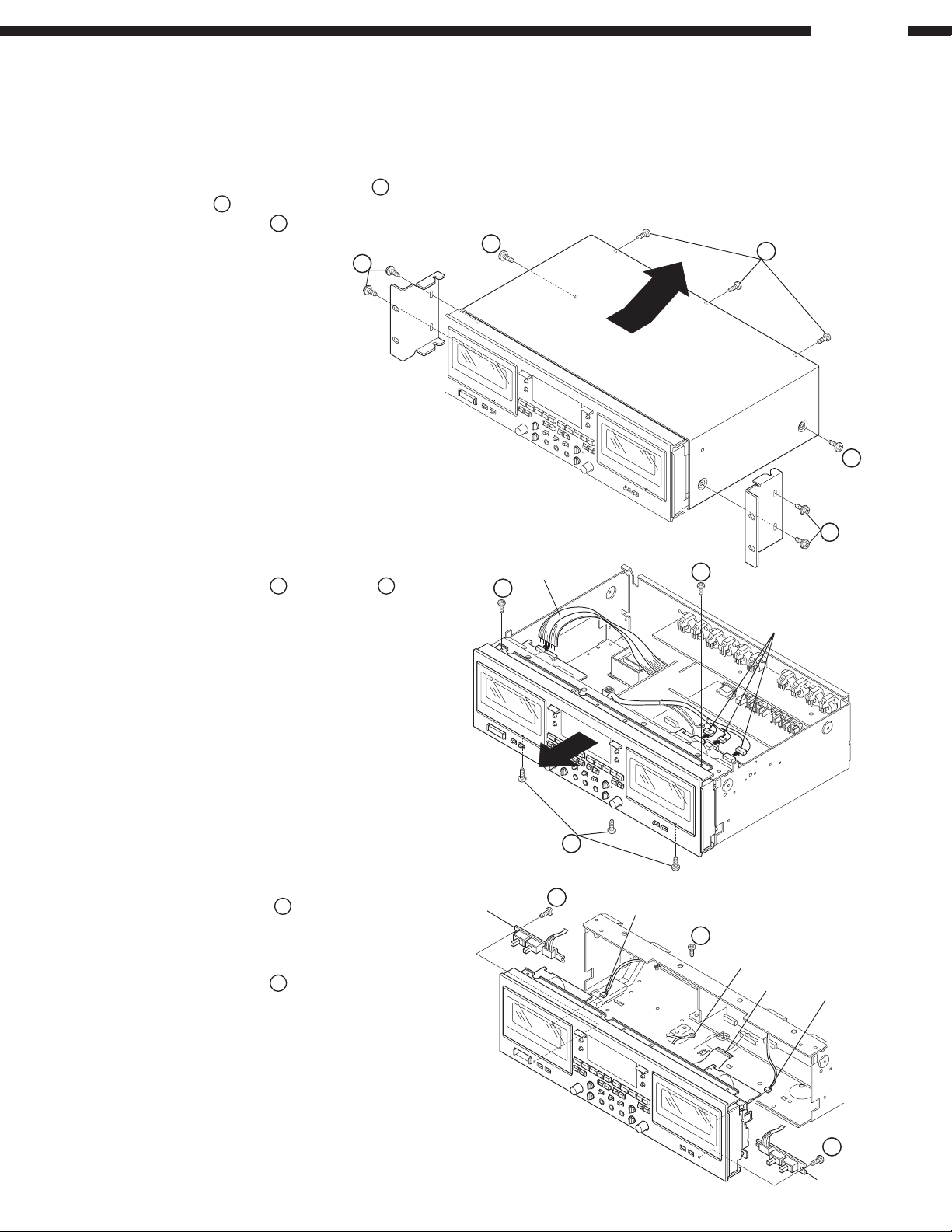
1. Top Cover
(1) From both sides, remove 4 screws 1, Bracket, and
2 screws
(2) Remove 3 screws 3 on the rear, then detach the
Top Cover to the arrow direction.
.
2
1
DN-780R
3
2
2. Front Panel
(1) Remove 2 screws 4 and 3 screws 5 from top
and bottom of the Front Panel.
(2) Disconnect the wire and 3 connectors from the
Cassette Mecha., then detach the Front Panel to
the arrow direction.
(3) Remove the screw
(4) Disconnect FFC.
(5) From the Cassette Mecha., disconnect
2 connectors.
(6) Remove 2 screws
SWB UNIT.
to free earth wire.
6
7
to detach the SWA UNIT and
SWA UNIT
Wire
1
4
Connector
5
7
Connector
6
Earth Wire
FFC
Connector
7
SWB UNIT
3
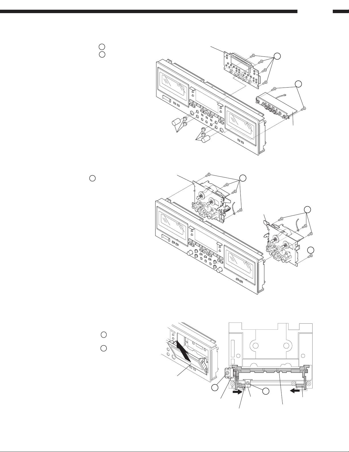
3. DISPLAY P.W.B./VOLUME P.W.B.
(1) Pull out 6 knobs on the front.
(2) Remove 9 screws 8 on the DISPLAY P.W.B.
9
(3) Remove 2 screws
on the MIC UNIT.
knob
DN-780R
DISPLAY P.W.B.
8
9
MIC UNIT
knob
4. Cassette Mecha. A & B
Remove 4 screws each on both Cassette
Mecha. A and B.
5. Cassette Door
(1) Take off the Cassette Window on the front.
(2) Remove the screw to detach
the Mini-damper.
(3) Remove the screw
Bracket.
(4) With pushing the shaft in the arrow directions,
no spring side first, detach the Cassette Door.
to detach the Door
Cassette Mecha. A
Cassette Mecha. B
Cassette Window
Mini-damper
Spring
Door Bracket
Cassette Door
Shaft
4
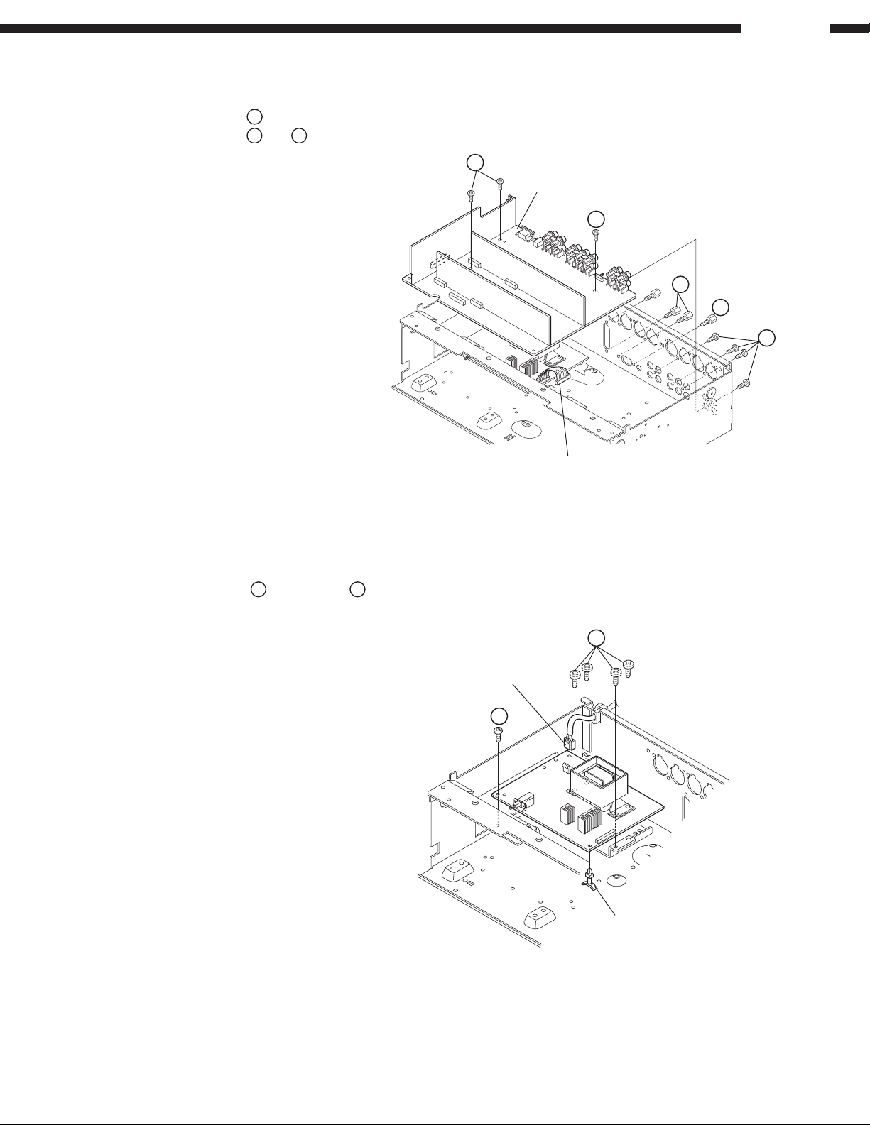
6. Audio P.W.B.
(1) From the Audio P.W.B., disconnect the connector.
(2) Remove 3 screws !.
"
(3) Remove 4 screws
and # each on the rear.
DN-780R
!
Audio P.W.B.
!
#
#
"
7. Power P.W.B.
(1) Disconnect the power connector.
$
(2) Remove the screw
(3) Release the P.W.B. holder.
and 4 screws %.
Connector
%
Power Connector
$
P.W.B. Holder
5
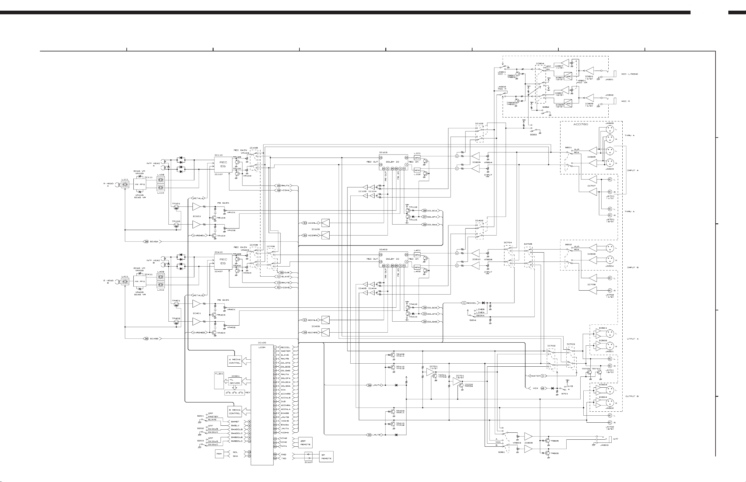
BLOCK DIAGRAM
(Option)
DN-780R
1 5678
32
4
A
B
C
D
E
6
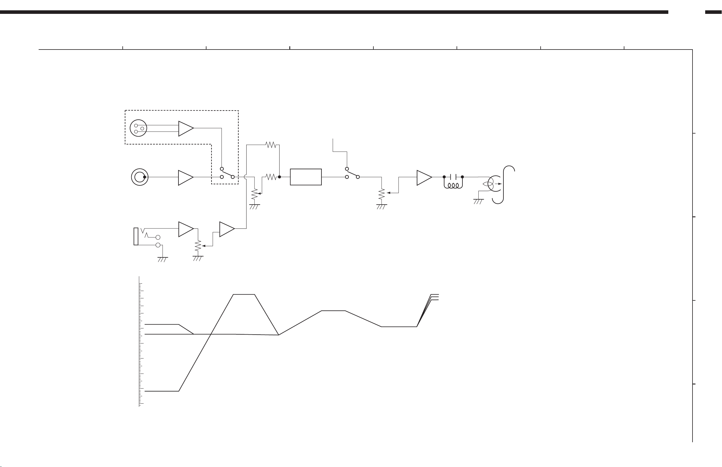
LEVEL DIAGRAMS
XLR -17.5dB
MIC -62dB
DCA -24dB
-24.5dB
-8.2dB
-19dB
+2.5dB(METAL)
+1dB (CHROME)
-1dB (NORMAL)
+2.5dB
-10dB
-50dB
-60dB
-70dB
-20dB
-40dB
-30dB
0dB
(dBV)
IC103(403)
HA12170
IC605(606)
XLR
7(1)
IC707(708) VR804(805)
VR103(403)
IC108(408) IC110(410)
RCA
1(7) 30(1) 16(15) 1(7)
IC807
7(1)
IC801(805)
7
LINE IN
MIC
ACD 780 (Option)
0dB=0.775V
* MIC MIDE = REC
MIC AGC = OFF
RECORDING SYSTEM
INPUT FREQUENCY 400Hz
DN-780R
1 5678
32
4
A
B
C
D
E
7
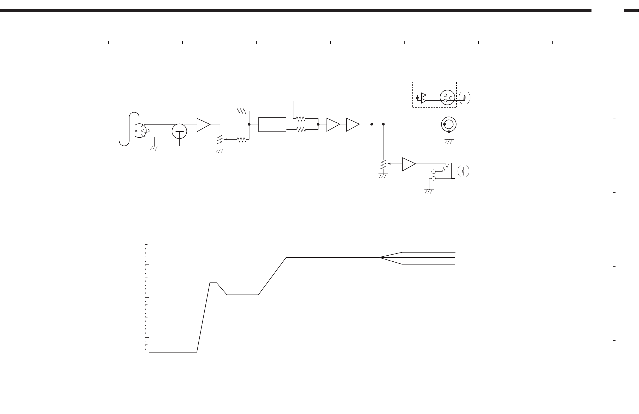
DN-780R
-71dB
-19dB
-28dB
+4dB(XLR)
0dB(RCA)
-5dB(HEAD PHONE)
-10dB
-50dB
-60dB
-70dB
-20dB
-40dB
-30dB
0dB
(dBV)
0dB=0.775V
IC103(403)
HA12170
XLR
TR101(401)
VR101(401)
IC105(405)
IC601(603)
LOAD
600 ohm
LOAD
33 ohm
IC104(404)
IC101(401)
NJM2068
3(5)
1(7)
1(7) 1(7)
28
(3)
22
(9)
LINE OUT
HEAD PHONE
RCA
ACD 780 (Option)
PLAYBACK SYSTEM
TCC-130 DOLBY B-TYPE
1 5678
32
4
A
B
C
D
E
8
ADJUSTMENT
ADJUSTING AND CHECKING THE
MECHANISM SECTION
1. Replacing Pinch Roller
Before replacing the pinch roller, clean the tape contact
surface of the pinch roller and the capstan shaft.
Most causes of poor tape transport can be traced to dirty
pinch roller and capstan shaft.
Removing the pinch roller
Remove the clips that press the pinch roller and pull the
pinch roller forward remove it.
After replacing, run a padles C-90 tape to check for tape
curls at the tape guide section of the head.
DN-780R
Capstan shaft
Pinch roller
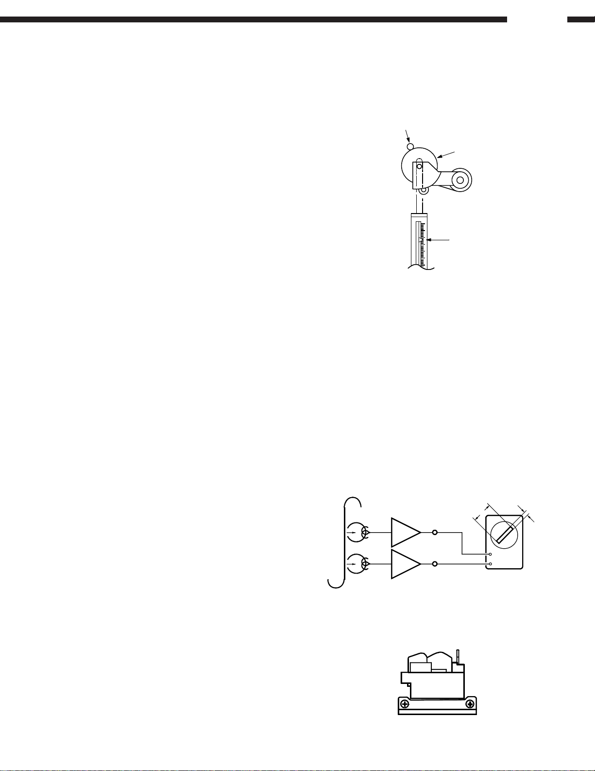
2. Checking the pressure Force of the Pinch
Roller
In the playback mode, hook a spring weight onto the
bracket at the center of the pinch roller. After separating
the pinch roller from the capstan shaft allow the pinch roller
to contact the capstan shaft again. Check to make sure
the spring weight reads between 250 ~ 350g when the
pinch roller starts to rotate.
Replace the pinch roller when it does not conform to the
standard specification values.
3. Replacing the Head Ass'y
(1) Removing the head Ass'y
1. Remove the head base mounting screws.
2. Remove the head base from the lead holder and
the wire connectors.
(2) Head Ass'y Installation
1. Assembly is the reverse of disassembly.
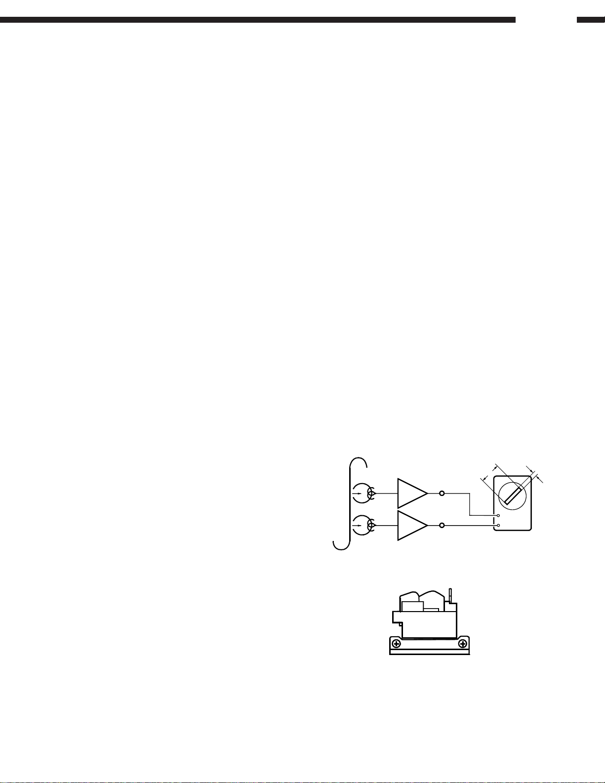
4. Adjusting the R/P HEAD
Azimuth adjustments
Set test tape A-BEX TCC-153 so that the A surface faces
forward, and adjust accordingly.
(1) Playback FWD. Turn the azimuth adjustment nut so
that the Lissajous waveform (A) is at maximum scale
and the Lissajous waveform (B) is at minimum scale.
(2) Playback REV. Turn the azimuth adjustment nut in
the same manner as (1), above.
(3) Make further adjustments to (1) and (2), above.
(4) Apply torsion locks to the adjusted nuts.
Note: Only the azimuth adjustment is necessary; no height
and tilt angle adjustments are required.
A-BEX TCC-153
PB Amp
L
R
LINE OUT
250 ~ 350g
A
B
V
H
R/P Head
FWD REV
9
DN-780R
5. Checking the Take-up Torque
Load the cassette type torque meter
FWD side .........SONY TW2111A
REV side ..........SONY TW2121A
Check to make sure that the average torque meter reading
is within 30 ~ 70g-cm during playback. If it is not within
this range, check the voltage (approx. 4V) of the reel motor.
After the verification, replace the reel motor if there is no
problem with the voltage value.
6. Checking the FF and REW Torques
Load the cassette type torque meter (SONY TW2231).
Check to make sure the torque meter indicates within
90 ~ 180g-cm at the end of FF and REW.
7. Checking the Back Tension Torque During
Record/Playback
Load the cassette type torque meter
FWD side .........SONY TW2111A
REV side ..........SONY TW2121A
Check to make sure the torque meter reads between
2 ~ 6g-cm during playback and that there is no unevenness.
8. Checking the FF and REW Times
Load a C-60 cassette tape (TDK AC-514); check to make
sure the tape is fast forwarded or rewound within 85 ~
115 seconds. If it is not within this range, check sections 5
and 7.
9. Checking the Operation of the Erase
Prevention, Metal and Chrome Switch
Confirm that the sensor arm properly detecting the tape
type detection holes on the cassette housing.
Caution on adjusting
(1) Before adjusting, clean the head surface, capstan and
the pinch roller with a gauze or cotton swab moistened
with alcohol.
(2) Demagnetize the R/P HEAD and the E HEAD with a
head eraser.
(3) Completely demagnetize the adjustment screwdriver.
(4) Unless instructed otherwise, set the various controls
as follows:
INPUT volume ....................... maximum
DOLBY NR button ................. OFF
TAPE SPEED-A (-B) .............Center click position
PHONES SELECT ................MIX
INPUT SELECT .................... LINE B
1. Tape Transport Check
Load the transport check cassette. In the operational mode,
illuminate the fixing guides of the R/P HEAD with a lamp
and check to make sure the tape edge does not come in
contact with the tape guide section.
The tape transport is the most important element in
determining the performance of a cassette deck.
Avoid moving the various adjustment screws, nuts, etc.,
as much as possible. Refer to the pages on "Adjusting
and Cheking the Mechanism Section" when replacing or
adjusting the R/P HEAD.
2. Adjusting the Azimuth
(1) After completing the tape transport check, load the
test tape (A-BEX TCC-153).
(2) Playback (both FWD side and REV side) the test tape;
adjust the azimuth screw so that section A of the
Lissajous waveform is maximum and section B is
minimum.
ADJUSTING THE ELECTRICAL SECTIONS
Measuring instruments necessary for
adjustments
(1) Audio signal generator
(2) Variable resistance attenuator
(3) Electronic voltmeter
(4) Oscilloscope
(5) Frequency counter
(6) Adjustment screwdriver.
(7) Trap coil adjustment square stick
(8) Test tapes (SONY TY-224)
(A-BEX TCC-130, TCC-153, TCC-262B/162B)
(TDK AC-514)
(9) Transport Check cassette tape (A-BEX TCC-902)
A-BEX TCC-153
FWD REV
PB Amp
L
R
LINE OUT
R/P Head
A
V
H
B
10
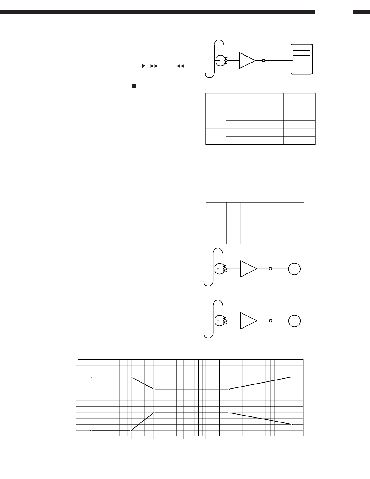
3. Checking and Adjusting the Tape Speed
(1) Connect the frequency counter to the LINE OUT
terminal and load test tape (SONY TY-224).
(2) Load cassette tapes on both cassette decks A and B.
Next, on the deck (A or B) whose speed is to be
adjusted, while holding down the
buttons of deck A together, press the POWER switch.
After the power has been on for about two seconds,
the Remote Control Indicator " " in Display will light
up and the cassette deck will begin to play in speed
adjustment mode.
(Speed adjustments can not be made, unless this
mode is first selected.)
(3) First high speed adjustments, press the DUBBING
SPEED "HIGH" Button and use VR101 for Casette
Deck A and VR102 for Cassette Deck B.
(Note that speed adjustment mode is cancelled when
the tape is ejected.)
(4) After completing high speed adjustments, press the
DUBBING SPEED "HIGH" Button again then tape
speed is slow (Normal speed). And start normal speed
adjustments, use Control Unit VR103 for Cassette
Deck A and VR104 for Cassette Deck B.
, , and
SONY TY-224
Mode
Normal
speed
High
speed
PB Amp
LINE OUT
Adjusting volume
A/B
A
B
A
B
number
VR-103
VR-104
VR-101
VR-102
DN-780R
F. Counter
F.
counter
(Hz)
3005±5
3005±5
6010±10
6010±10
4. Playback System Adjustment
(1) Playback level
Playback a test tape for Dolby standard level (A-BEX
TCC-130). Adjust (Lch) and (Rch) so that the LINE
OUT terminal level is at 0 dB (775 mV).
(2) Verifying playback frequency characteristics
Playback the test tape (A-BEX TCC-262B/162B) and
verify that the frequency characteristics conform to
the specified standard.
Note: Before checking the playback frequency response,
first adjust the azimuth using the 8 kHz signal at the
beginning of the test tape (A-BEX TCC-262B). Also,
after checking the playback frequency, make sure
to readjust the azimuth with the test tape (A-BEX
TCC-153) and then lock the adjustment screw.
Playback frequency characteristics
(db)
+6
+
5
4
+
+3
+2
1
+
0
1
−
−2
3
−
−4
−5
6
−
20
10050
200
500
Playback Level
DECK L/R
A
B
A-BEX TCC-130
A-BEX TCC-262B/162B
1 k
Adjusting volume number
L VR-101
R
L
R
PB Amp
PB Amp
2 k
Tape: A-BEX TCC-262B/162B
VR-102
VR-401
VR-402
LINE OUT
LINE OUT
5 k
10 k 12 k
V.V
V.V
20 k (Hz)
11
DN-780R
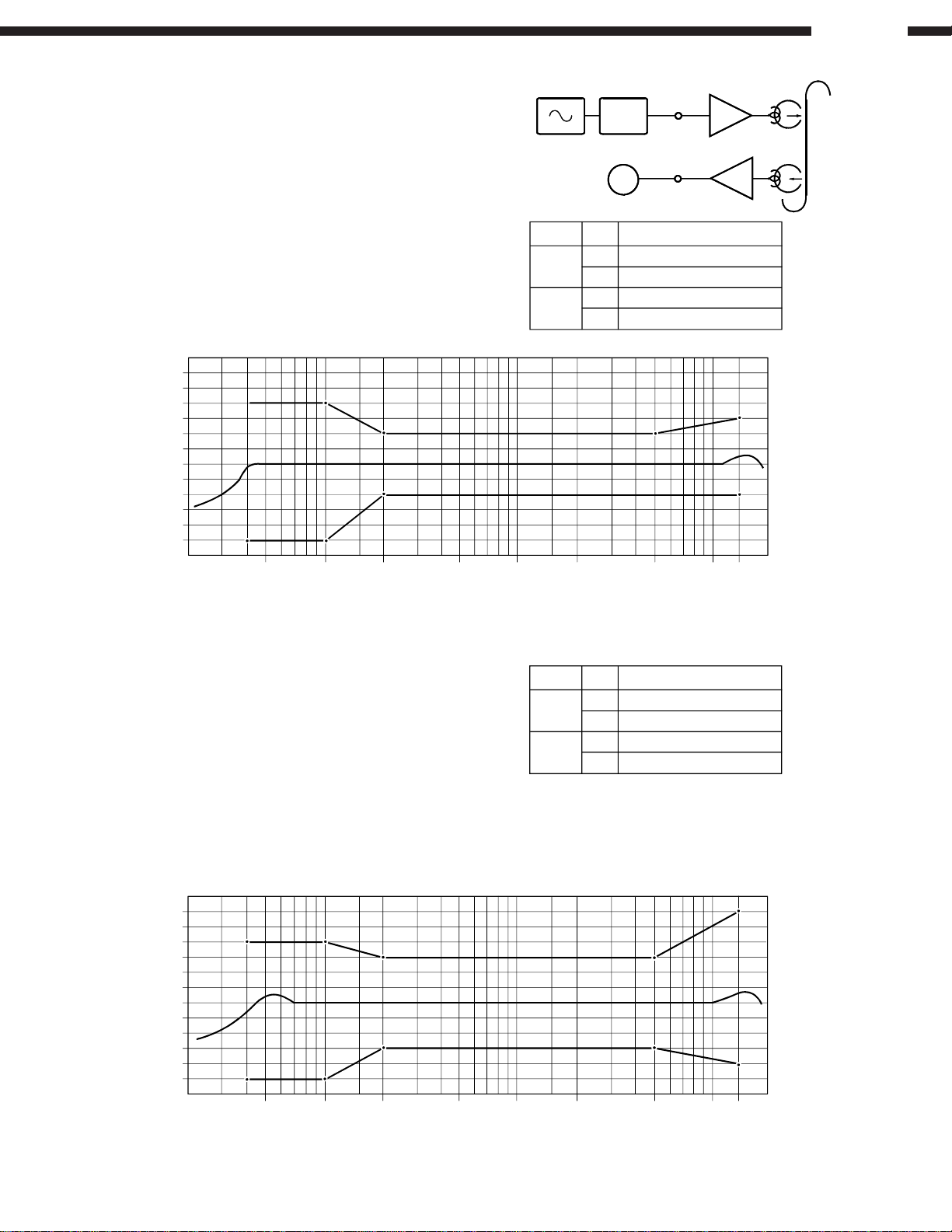
5. Recording System Adjustment
5-1. Adjusting recording/playback comprehensive
frequency characteristics.
(1) Load a test tape TDK AC-514.
Record with a -20 dB 1 kHz input level signal into
the LINE IN terminal and playback.
(2) Make a sample recording using a 12 kHz input
signal and playback this recording. Adjust (left
channel) and (right channel) so that they conform
to the following specified characteristics.
(db)
+6
+5
+
4
+
3
2
+
+1
0
−1
−2
−3
−4
5
−
−
6
20
Record/Playback Overall Frequency Response
10050
200
500
ATT
Frequency Responce
DECK L/R
L
A
B
1 k
R
L
R
2 k
Tape
Dolby NR
Level
REC Amp
LINE IN
LINE OUT
V.V
PB Amp
Adjusting volume number
5 k
: AC-514
: Off
: −20 dB From Dolby Level
VR-105
VR-106
VR-405
VR-406
10 k 12 k
20 k (Hz)
5-2. Recording/Playback Level Adjustment
(1) Load the test tape TDK AC-514. Make a sample
recording with the 1 kHz (-20 dB) signal and play
this section back.
(2) Adjust (Lch) and (Rch) so that the output from
LINE OUT terminal is the same as the output at
recording monitoring time.
5-3. Dolby C recording and playback comprehensive
frequency characteristics verification
(1) Set the Dolby NR switch at "C" position.
(2) Use a test tape TDK AC-514 and record and
playback as in item 5-1 to verity that they satisfy
the characteristics standards.
Dolby C Record/Playback Overall Frequency Response
(db)
6
+
+5
4
+
+3
2
+
+
1
0
−1
−
2
3
−
−4
5
−
−6
20
10050
200
500
R/P Level Adjustment
DECK L/R
L VR-103
A
B
1 k
R
L
R
2 k
Tape
Dolby NR
Level
Adjusting volume number
5 k
VR-104
VR-403
VR-404
10 k 12 k
20 k (Hz)
: AC-514
: On C
: −20 dB From Dolby Level
12

DN-780R
MECHANISM OPERATING TIME CHECK
The total operating time of the mechanism is registered in this unit.
Check and refer to it when replacing the mechanism, head, or motor.
1. Displaying the Operating Time
(1) Set the power to on while pressing the “STOP ( )”, “RESET”, and “MEMO” buttons of the Deck A together.
(2) The and buttons of the Deck A are used to switch the display for the Deck A mechanism or for the Deck B mechanism.
Ex.: The operating time of the Deck A mechanism
Operating time (unit: hour)
The operating time of the Deck B mechanism
Operating time (unit: hour)
* “FuLL” is displayed when exceeding “9999”.
2. Deleting the Operating Time
When replacing the associated parts, delete the registered operating time as follows.
Press the “COUNTER MEMO” and “RESET” buttons of the Deck A together at once.
The displayed mechanism operating time of the selected Deck is set to “0000”.
13
SEMICONDUCTORS
IC’s
DN-780R
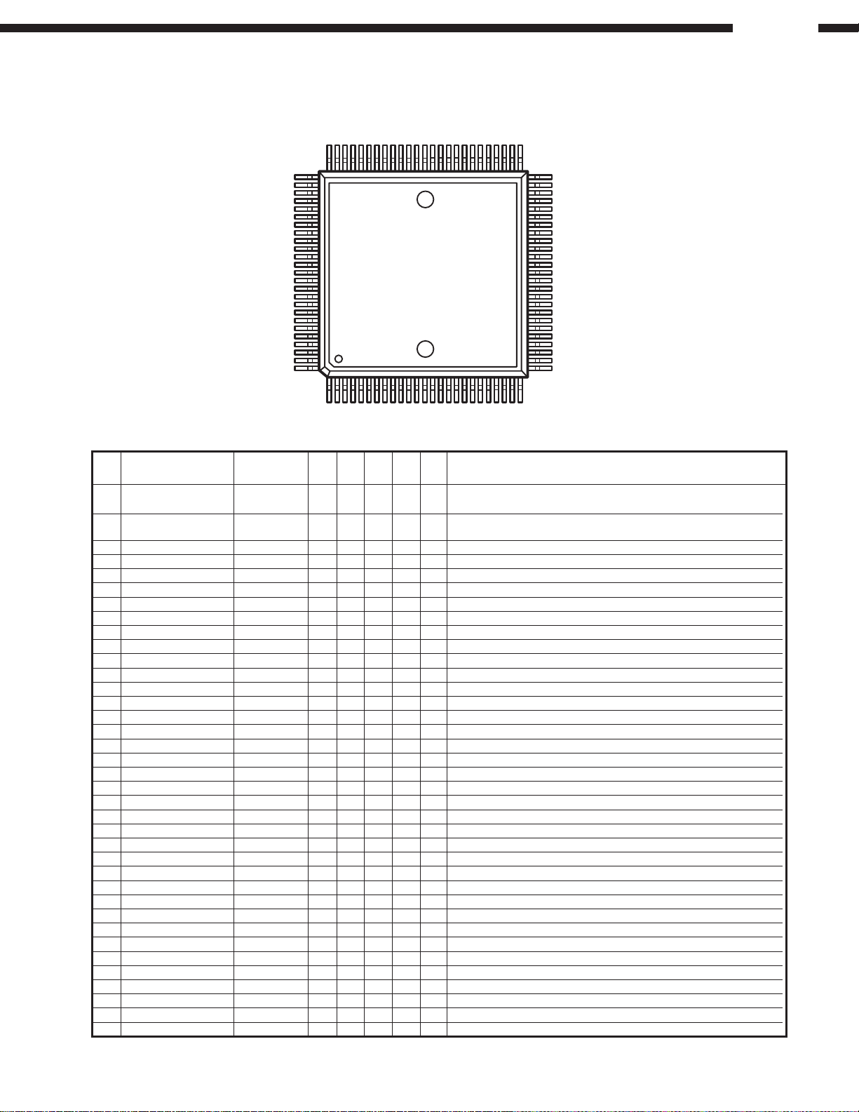
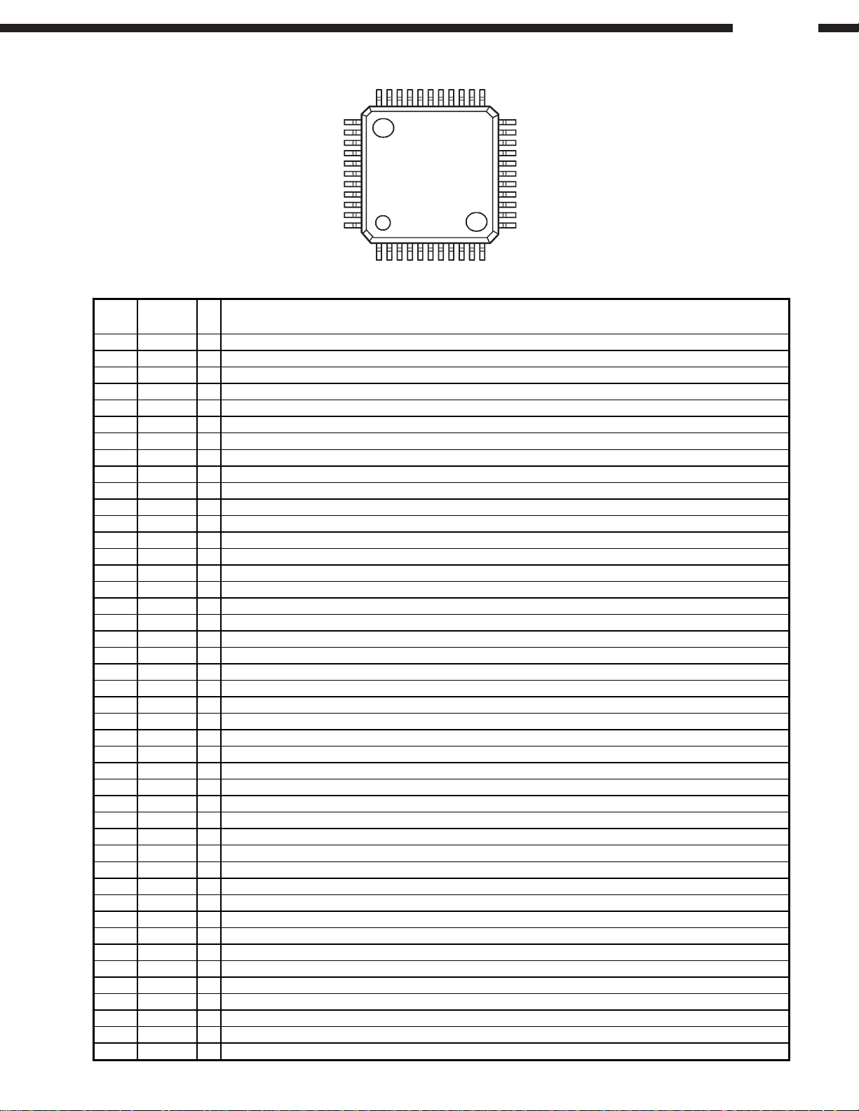
MN102L62G (IC105)
µµ
µCOM
µµ
75
76
100
1
51
50
26
25
MN102L62G Terminal Function
Pin
No.
1 P60, WAIT PRECSEL O Pd L L
2 P61, _RE PIRINH O Pd L L
3 P62, _WEL PMASTER O Pd L L
4 P63, _WEH PSLAVE O Pd L L
5 P50, _CS0 PSWMST I Pu H Selection switch. L: MASTER /H: Other
6 P51, _CS1 PSWSLV I Pu H Selection switch. L: SLAVE /H: Other
7 P52, _CS2 PSWADLB I Pu H Selection switch. L: Dolby B /H: Other
8 P53, _CS3 PSWADLC I Pu H Selection switch. L: Dolby C /H: Other
9 P54, _BREQ PSWBDLB I Pu H Selection switch. L: Dolby B /H: Other
10 P55, _BRACK PSWBDLC I Pu H Selection switch. L: Dolby C /H: Other
11
12 P57, _WORD Reserved I 0V L Not used.
13 P20, A00 PRMUTB O Pu H H B mechanism REC MUTE change signal. H: MUTE ON
14 P21, A01 PDOLOFB O Pd L L B mechanism Dolby on / off change signal. H: Dolby OFF
15 P22, A02 PDOLBCB O Pu H H B mechanism Dolby B / C change signal. H: Dolby B
16 P23, A03 PDOLSWB O Pd L L B mechanism Dolby Switch change signal. H: PLAY mode
17 Vdd Vdd Power supply (+5V)
18 SYSCLK SYSCLK O OSCI ×1/2 is outputted.
19 VSS VSS GND(0V)
20 XI XI I 0V L L Not used. It connects with GND.
21 XO XO Not used. OPEN
22 VDD VDD Power supply (+5V)
23 OSCI OSCI I There is 0.16% of an error by baud rate 9600bps setup
24 OSCO OSCO O OSCI is outputted.
25 MODE MODE I H: Single tip mode
26 P24, A04 PRMUTA O Pu H H A mechanism REC MUTE change signal. H: MUTE ON
27 P25, A05 PDOLOFA O Pd L L A mechanism Dolby on / off change signal. H: Dolby OFF
28 P26, A06 PDOLBCA O Pu H H A mechanism Dolby B / C change signal. H: Dolby B
29 P27, A07 PDOLSWA O Pd L L A mechanism Dolby Switch change signal. H: PLAY mode
30 P30, A08 PRSVI1 I Pu H Preliminary input terminal 1
31 P31, A09 PRSVI2 I Pu H Preliminary input terminal 2
32 P32, A10 PRSVI3 I Pu H Preliminary input terminal 3
33 P33, A11 PRSVI4 I Pu H Preliminary input terminal 4
34 VDD VDD Power supply (+5V)
35 P34, A12 Reserved I 0V L Not used.
36 P35, A13 Reserved I 0V L Not used.
37 P36, A14 Reserved I 0V L Not used.
Pin Name
P56, ALE, _ALE, _BSTRE
Reserved I 0V L Not used.
Symbol
I/O
DET Ext Ini Res
Recording selection to B mechanism.
L: Slide switch setup / H: Deck A line in
Infrared remote control selection. L: Infrared remote control
use is possible./ H: Infrared remote control use is impossible.
MASTER function setup, turns on at the time of DUPLICATE operation.
SLAVE function setup, turns on at the time of DUPLICATE operation.
Function
14

DN-780R
Pin
No.
38 P37, A15 Reserved I 0V L Not used.
39 P40, A16 PSCL O Pu H H EEPROM communication clock signal.
40 P41, A17 PSDA I/O Pu H In
41 P42, A18 PSELEEP I Pd L L
42 P43, A19 PMIX O Pd L L A mechanism line out. H: The mix output of A+B
43 VSS VSS GND(0V)
44 P44, AN4, A20 PKIN2 I Lv Pu H A / D conversion is used.
45 P45, AN5, A21 PREMO I Lv Pu H A / D conversion is used.
46 P46, AN6, STOP, A22 PADINRB I Lv Pd L A / D conversion is used.
47
48 P80, TM0IO PRECR I Pu H Mechanism input signal. H: REC of RVS is improper.
49 P81, TM1IO PRECF I Pu H Mechanism input signal. H: REC of FWD is improper.
50 P82, TM2IO PHALH I Pu H Mechanism switch. H: No tape.
51 P83, TM3IO PSWCOM O Pu H H Mechanism scan signal. H: A mechanism selection
52 P84, TM4IO PDUB O Pd L L Duplicate output signal. H: Duplicate
53 P85, TM5IO PRSVO4 O 0V L L Preliminary output terminal 4
54 VDD VDD Power supply (+5V)
55 P86, TM6IOA PRMTOUT O Pu H H Remote output signal.
56 P87, TM6IOB Reserved I 0V L GND(0V) and connection.
57 P90, TM6IC PQSENA I Pu H
58 P91, TM7IOA PQSENB I Pu H
59 P92, TM7IOB PRSVO1 O 0V L L Preliminary output terminal 1
60 P93, TMI7IOC PRSVO2 O 0V L L Preliminary output terminal 2
61 VSS VSS GND(0V)
62 P94, AN0 PADINRA I Lv Pd L A / D conversion is used
63 P95, AN1 PADINLA I Lv Pd L A / D conversion is used
64 P96, AN2 PKIN0 I Lv Pu H A / D conversion is used
65 P97, AN3 PKIN1 I Lv Pu H A / D conversion is used
66 VDD(VPP)VDD Power supply (+5V)
67 P70, SBT0 _PFLNCS O Pu H H Connects with NCS. L: Select
68 P71, SBI0 RxD I Pu H It is used as a serial port. (It is 9615.38bps in 20MHz.)
69 P72, SBO0 TxD O Pu H H It is used as a serial por t. (It is 9615.38bps in 20MHz.)
70 P73, SBT1 PFLCLK O Pu H H Connects with a clock.
71 P74, SBI1 PFLRD I Pu H Connects with SDO. (Key input data)
72 P75, SBO1 PFLSD O Pu H H Connects with SDI
73 TEST1 TEST1 I Pu A pull-up is carried out by 47k. (Recommendation)
74 TEST2 TEST2 I Pu A pull-up is carried out by 47k. (Recommendation)
75 _NMI _NMI I Pu H A pull-up is carried out.
76 PA0, _IRQ0 PPLSB I Ed Pu H
77 PA1, _IRQ1 PPLSA I Ed Pu H
78 PA2, _IRQ2 PPOFF I Pu H
79 PA3, _IRQ3 PEXTIN I Pu H EXT. IN input signal.
80 PA4, _IRQ4 PREMOTE I Ed Pu H RC-5/Infrared remote signal input.
81 PA5, DSEP PEXTOUT O Pu H H EXT.OUT output signal.
82 _RST _RESET I Lv L Reset signal. L: Reset
83 VDD VDD Power supply (+5V)s
84 P00, D00, AD00 PSOLHB O Pd L L B mechanism solenoid hold signal. H: Hold
85 P01, D01, AD01 PSOLKB O Pd L L B mechanism solenoid kick signal. H: kick
86 P02, D02, AD02 PRELRB O Pd L L B mechanism reel motor inversion signal. H: Inversion signal ON.
87 P03, D03, AD03 PRELFB O Pd L L B mechanism reel motor rotation signal. H: rotation signal ON.
88 P04, D04, AD04 PCAPB O Pd L L B mechanism capstan control signal. H: Capstan motor-on
89 P05, D05, AD05 PBIASB O Pd L L B mechanism bias signal. H: Bias
90 P06, D06, AD06 PLMUTB O Pd L L B mechanism line mute signal. L: Mute on
91 P07, D07, AD07 PHIGHB O Pd L H High speed signal B mechanism. L: High
92 VSS VSS GND(0V)
93 P010, D08, AD08 PSOLHA O Pd L L A mechanism solenoid hold signal. H: Hold
94 P011, D09, AD09 PSOLKA O Pd L L A mechanism solenoid kick signal. H: kick
95 P012, D10, AD10 PRELRA O Pd L L A mechanism reel motor inversion signal. H: Inversion signal ON.
96 P013, D11, AD11 PRELFA O Pd L L A mechanism reel motor rotation signal. H rotation signal ON.
97 P014, D12, AD12 PCAPA O Pd L L A mechanism capstan control signal. H: Capstan motor-on.
98 P015, D13, AD13 PBIASA O Pd L L A mechanism bias signal. H: Bias
99 P016, D14, AD14 PLMUTA O Pd L L A mechanism line mute signal. L: Mute on
100 P017, D15, AD15 PHIGHA O Pu L H High speed signal A mechanism. L: High
Pin Name
P47, AN7, WDOUT, A23
Symbol
PADINLB I Lv Pd L A / D conversion is used.
DET Ext Ini Res
I/O
Function
EEPROM communication data input¾and¾output signal.
(The input port of the time of a power supply injection is carried out.)
EEPROM selection signal. L: Old EEPROM(X24C00)
H: New EEOPRM(S24C01)
A mechanism leader tape detected signal. L: Leader tape detection.
B mechanism leader tape detected signal. L: Leader tape detection.
It counts by DOWN EDGE. It rotates one time at three counts.
(DN-770R was taken as one rotation by six pulses by both edge.)
It counts by DOWN EDGE. It rotates one time at three counts.
(DN-770R was taken as one rotation by six pulses by both edge.)
An electric-power-failure detected signal. L: Electric-power-failure detection.
15
MN12510F (IC301)
y
FL DRIVER
DN-780R
33
34
23
22
44
1
MN12510F Terminal Function
Pin
No.
1 P21 O Segment output15 (hi-voltage proof output).
2 P20 O LED drive output (hi-voltage proof output).
3 P03 O No connection.
4 P02 O No connection.
5 P01 O Digit output10 (hi-voltage proof output).
6 P00 O Digit output9 (hi-voltage proof output).
7 DGT7 O Digit output8 (hi-voltage proof output).
8 DGT6 O Digit output7 (hi-voltage proof output).
9 DGT5 O Digit output6 (hi-voltage proof output).
10 DGT4 O Digit output5 (hi-voltage proof output).
11 NC
12 DGT3 O Digit output4 (hi-voltage proof output).
13 DGT2 O Digit output3 (hi-voltage proof output).
14 DGT1 O Digit output2 (hi-voltage proof output).
15 DGT0 O Digit output1 (hi-voltage proof output).
16 Vpp I ELP driver power supply, VPP: VDD -35V.
17 NC
18 V
19 OSC1 I Clock oscillation input terminal.
20 OSC2 O Clock oscillation output terminal.
21 Vss I Power supply terminal, Vss: 0V.
22 NCS I Chip select input, “L”: Serial input enable, “H”: Disable.
23 SCK I Clock input for serial transference.
24 SDI O Serial data input terminal.
25 SDO O Serial data output terminal.
26 P30 I Key scan input terminal.
27 P31 I Key scan input terminal.
28 P32 I Key scan input terminal.
29 P33 O LED drive output terminal.
30 P34 O LED drive output terminal.
31 SEG0 O Segment output1 (hi-voltage proof output).
32 SEG1 O Segment output2 (hi-voltage proof output).
33 SEG2 O Segment output3 (hi-voltage proof output).
34 SEG3 O Segment output4 (hi-voltage proof output).
35 SEG4 O Segment output5 (hi-voltage proof output).
36 SEG5 O Segment output6 (hi-voltage proof output).
37 SEG6 O Segment output7 (hi-voltage proof output).
38 SEG7 O Segment output8 (hi-voltage proof output).
39 P10 O Segment output9 (hi-voltage proof output).
40 P11 O Segment output10 (hi-voltage proof output).
41 P12 O Segment output11 (hi-voltage proof output).
42 P13 O Segment output12 (hi-voltage proof output).
43 P23 O Segment output13 (hi-voltage proof output).
44 P22 O Segment output14 (hi-voltage proof output).
mbol I/O Function
S
No connection.
No connection.
DD
I Power supply terminal, VDD: +5V r0.5V.
12
11
16
DN-780R
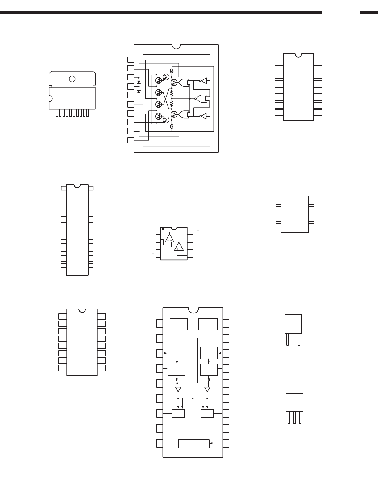
BA6109U1 (IC101, 102)
FRONT VIEW
1 10
HA12170NT (IC103, 403)
REC IN
Vcc
PB IN
REF
C/B/OFF
IA OUT
NR IN
VREF
PB OUT
SS1
SS2
CCR
HLS DET
LLS DET
REC OUT
1
2
3
4
5
6
7
8
9
10
11
12
13
14
15
30
29
28
27
26
25
24
23
22
21
20
19
18
17
16
REC IN
GND
PB IN
BIAS
M/R/P
IA OUT
NR IN
VREF
PB OUT
SS1
SS2
CCR
HLS DET
LLS DET
REC OUT
GND
V OUT 1
VZ 1
VR
F IN
R IN
VCC 1
VCC 2
VZ2
V OUT 2
1
2
3
4
5
6
7
8
9
10
BA10393F (IC103, 104)
BA15218F (IC104, 105, 107,
109, 110, 404, 405,
407, 409, 410, 701,
707~709, 807~810)
M5220FP (IC101, 401, 801, 805)
V
2
8
B OUTPUT
7
6
B –INPUT
B +INPUT
5
A OUTPUT
A –INPUT
A+INPUT
V
1
1
2
3
4
TC4053BF (IC102, 106, 108,
402, 406, 408, 702~706, 804)
IY
OY
Z-COM
OZ
INH
V
V
1
2
3
IZ
4
5
6
7
EE
8
SS
16
15
14
13
12
11
10
9
DD
V
Y-COM
X-COM
IX
OX
A
B
C
X24C00S (IC106)
EEPROM
NC
NC
NC
Vss
1
2
3
4
8
7
6
5
Vcc
NC
CLK
DATA
MAX202CSE (IC107)
C1+
1
2
V+
3
C1-
C2+
4
C2-
5
V-
6
R2IN
7
8
T2OUT
16
15
14
13
12
11
10
9
Vcc
GND
T1OUT
R1IN
R1OUT
T1IN
T2IN
R2OUT
m
PC1297CA (IC111, 411)
VST
VR1
VIN (R) 1
PH1
CIN1
COUT1
VOUT11
VOUT12
GND
STABI-
1
LIZER
2
ABSO
3
DET
PEAK
4
DET
5
6
7
VCA
8
9
PRE DRIVER
PRO-
TECTER
ABSO
DET
PEAK
DET
VCA
18
17
16
15
14
13
12
11
10
Vcc
VR2
CIN (R) 2
PH2
CIN2
COUT2
VOUT21
VOUT22
VIN (0)
NJM7805FA(S) (IC903)
NJM7808FA(S) (IC901)
FRONT
VIEW
Input
GND
Output
NJM7908FA (IC902)
FRONT
VIEW
Input
GND
Output
17
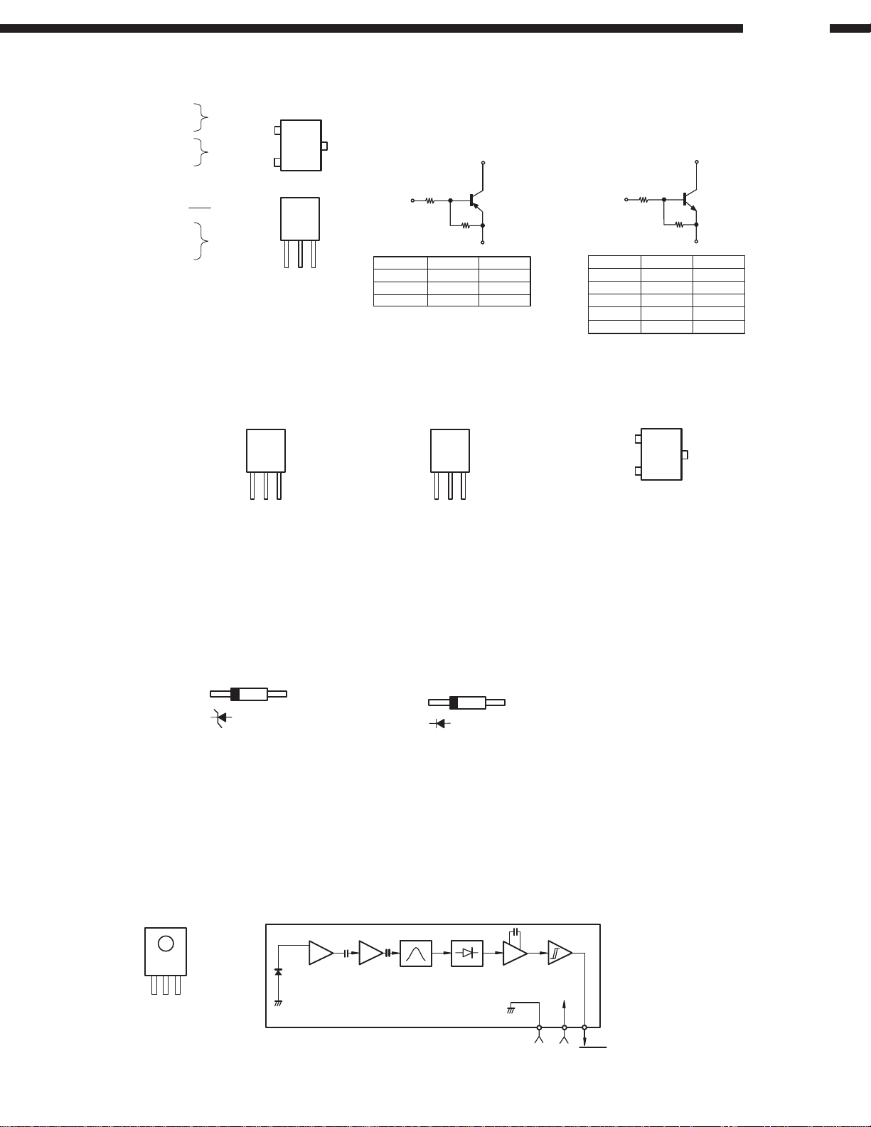
TRANSISTORS
l
DTA114EK
DTA144EK
DTC114EK
DTC144EK
PNP
NPN
DN-780R
B
TOP
C
VIEW
E
DTA Series
C
DTC Series
C
DTA144ES
DTC114ES
DTC124XS
DTC143ES
2SA933
2SB562(C)
2SC5395(E/F)
2SD2144
2SD468(C)
PNP
NPN
FRONT
VIEW
C
E
FRONT
VIEW
E
B
R1
B
R2
E
C
B
DTA114EK
DTA144EK
DTA144ES
R1
10kohm /
47kohm /
47kohm /W47kohm /
W
W
R2
10kohm /
47kohm /
W
W
W
DTC114EK
DTC114ES
DTC124XS
DTC143ES
DTC144EK
2SK373(Y)
R1
B
R2
R1
10kohm /
W
10kohm /W10kohm /
22kohm /W 47kohm /W
4.7kohm /W4.7kohm /
47kohm /W47kohm /
2SC2412K(S)
E
R2
10kohm /
W
W
W
W
KTC2875B
B
FRONT
VIEW
G
S
D
TOP
C
VIEW
E
DIODES/LED
l
HZS4C
HZS5C
HZS12B
HZS6C
HZS22C
HZS7B
MTZJ9.1A
OTHERS
l
GP1U271X (Remote Control Sensor)
(IC551)
TOP VIEW
CC
OUT
V
GND
V
Head
Amp
Limiter
Amp
1SS355
1SR35-400A
Detector &
BPF Integrator
Comparator
Hysteresis
Comparator
GND
VCCV
OUT
18
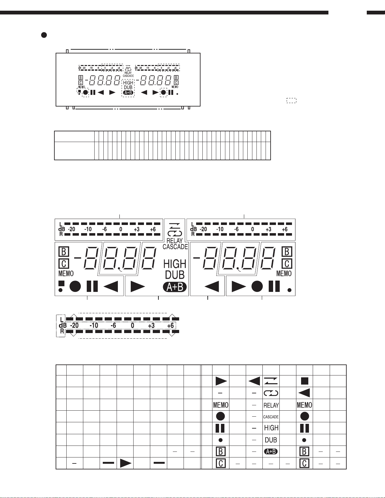
FL DISPLAY BJ881GHK (FL301)
PIN CONNECTION
3
3
3
3
3
3
3
3
3
3
2
2
2
2
PIN NO.
CONNECTION
1) F1,F2 ---------- Filament
NOTE
2) NP ------------- No pin
3) NX ------------- No extend pin
4) DL ------------ Datum line
5) 1G~8G ------- Grid
9
8
F
F
2
2
(NC pin should be electorically open on the PC board)
7
6
5
4
3
2
1
0
P
P
P
P
P
N
N
1
P
P
6
P
1
1
1
1
1
5
4
3
2
1
2
9
8
7
6
5
P
P
P
P
P
9
8
7
6
5
DN-780R
COLOR ILLUMINATION
Reddish Orange ----- Above pattern part
Green ------------------ Other
139
2
2
2
2
2
1
1
1
1
1
1
1
1
1
1
4
3
2
1
0
9
8
7
6
5
4
3
2
1
0
9
8
7
6
P
N
N
N
N
N
N
N
P
P
P
P
1
4
P
P
P
P
P
P
P
4
2
3
2
1
G
G
3
4
5
6
7
G
G
G
G
G
5
4
3
2
1
8
N
N
F
F
G
P
P
1
1
GRID ASSIGNMENT
1a 1a1a2a 1a 1a1a2a
3G
B1
B7
2G 1G
4G
Dp2 Dp1
ANODE CONNECTION
7G 6G 5G 4G 3G 2G 1G 8G
8G
P1
1a 1a 1a 1a 1a 1a B1 B1
7G
f
e
5G 6G 8G
B6
[2G,1G]
B12
7G 6G 5G 4G 3G 2G 1G
P9
2a 2a B7 B7
b
g
c
d
1b 1b 1b 1b 1b 1b B2 B2
P2
1f 1f 1f 1f 1f 1f B3 B3
P3
1g 1g 1g 1g 1g 1g B4 B4
P4
1c 1c 1c 1c 1c 1c B5 B5
P5
1e 1e 1e 1e 1e 1e
P6
1d 1d 1d 1d 1d 1d
P7
P8
Dp1 Dp2 S1 S1
B6 B6
P10
P11
P12
P13
P14
P15
P16
2b 2b B8 B8
2f 2f B9 B9
2g 2g B10 B10
2c 2c B11 B11
2e 2e
2d 2d
B12 B12
19
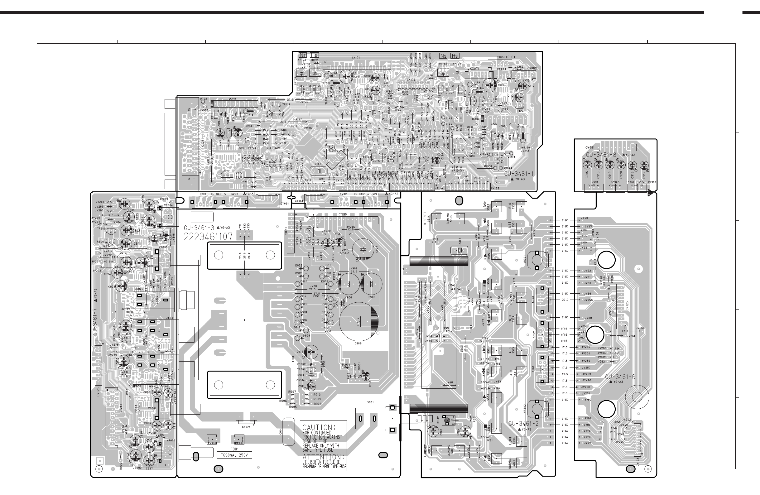
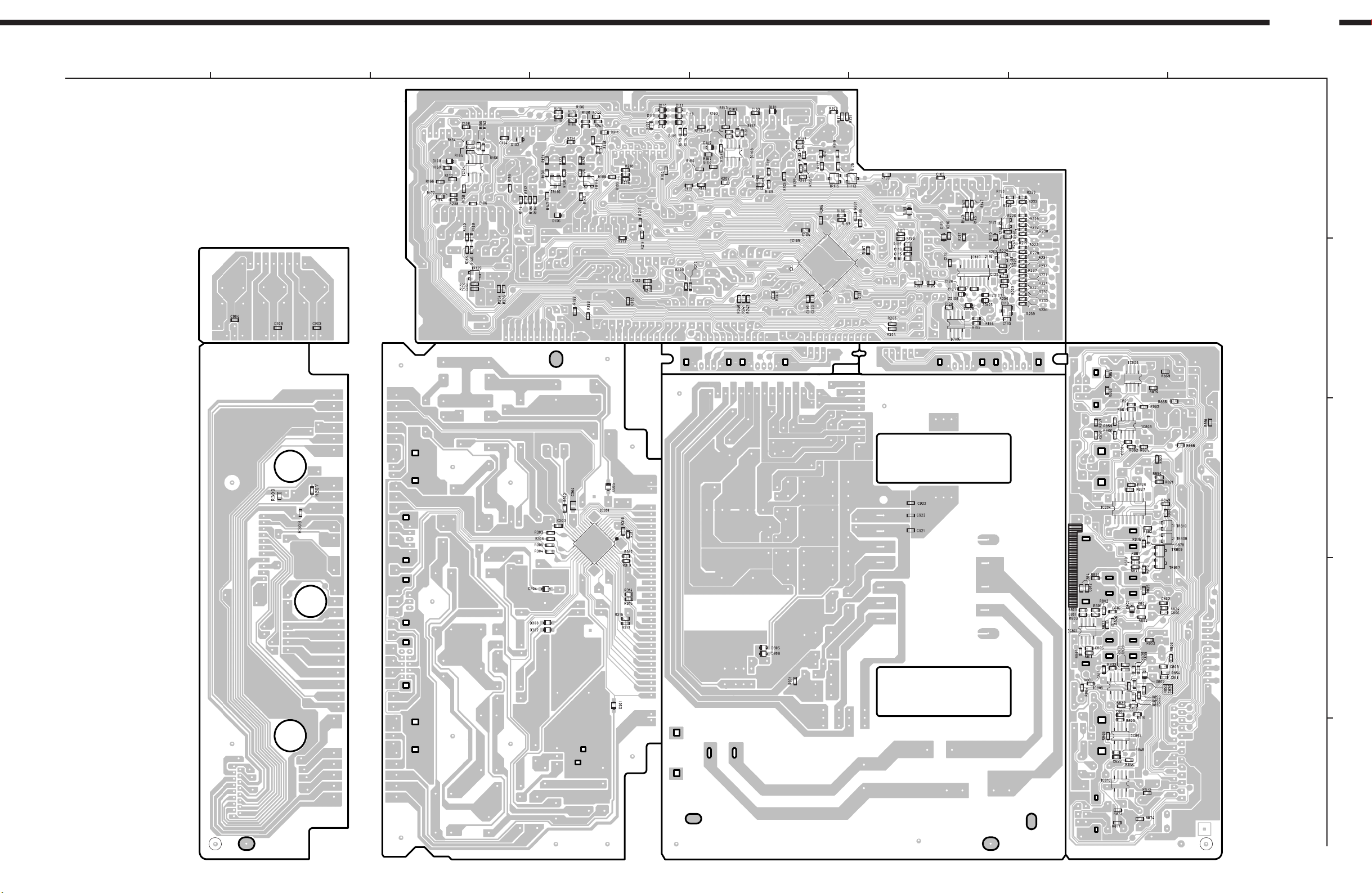
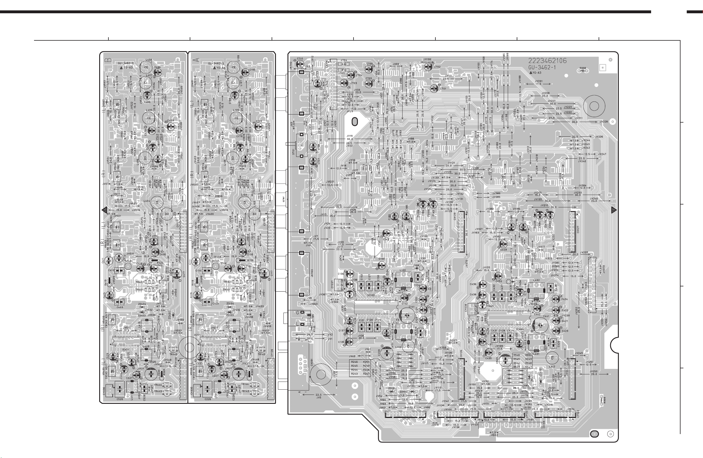
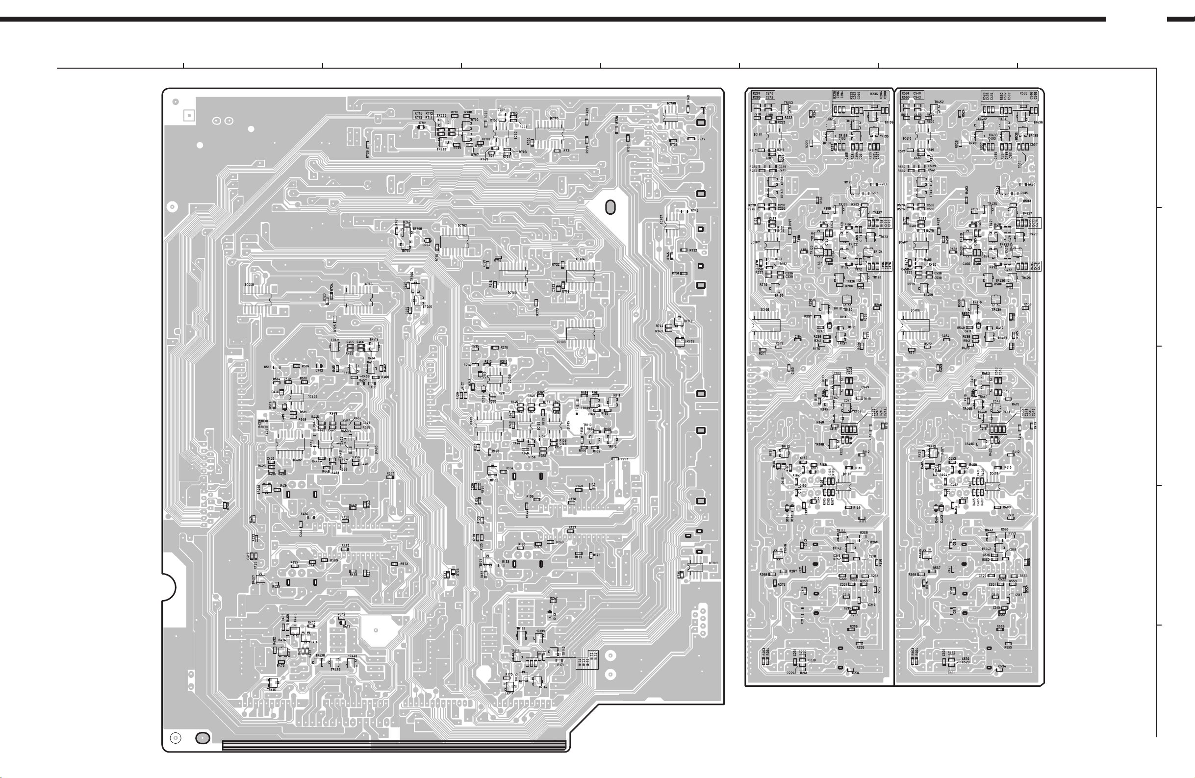
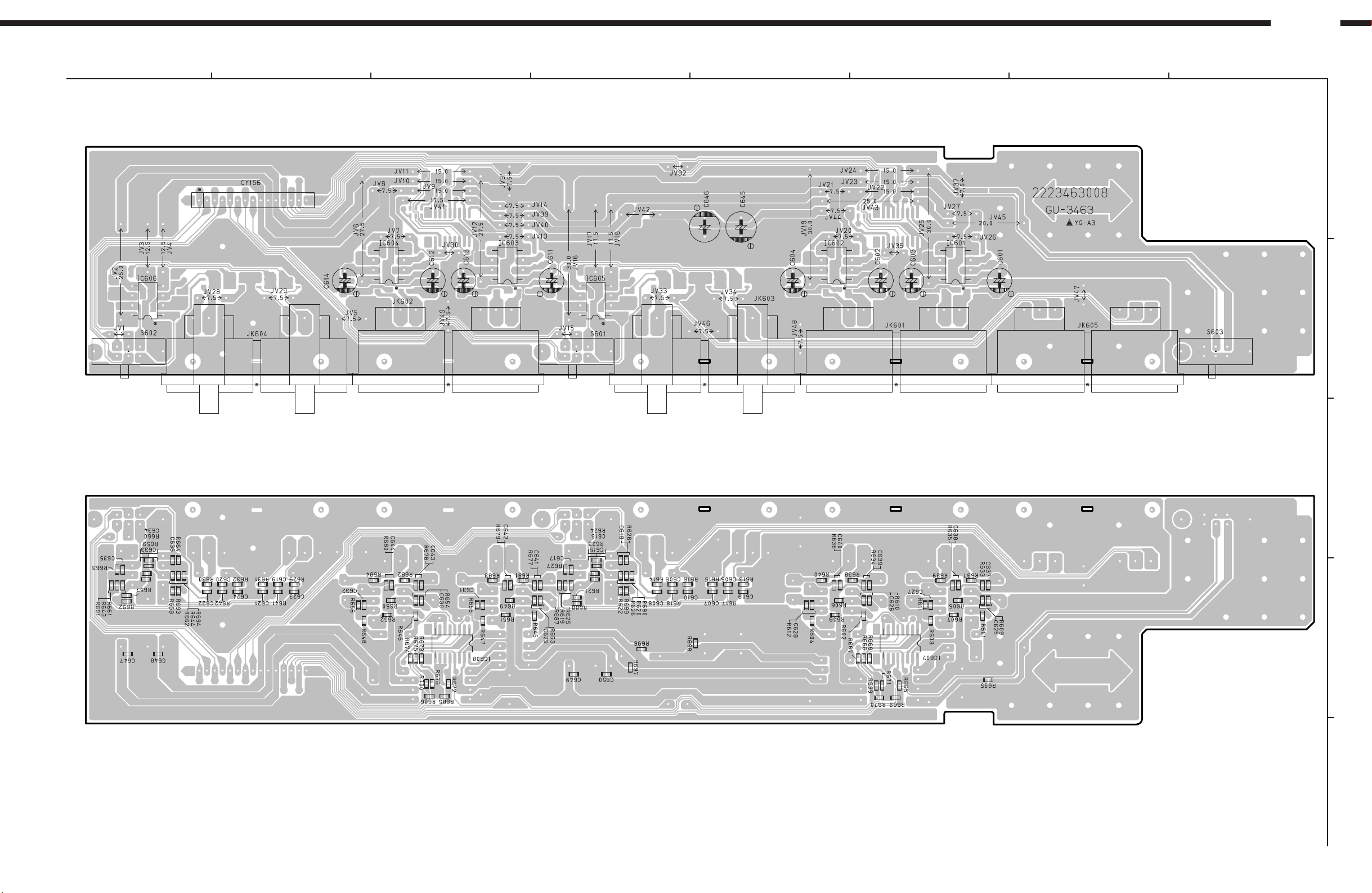
PRINTED WIRING BOARD
DN-780R
1
CONTROL POWER UNIT Ass'y
2
1
3
10
4
1
1
5
17
2
1
5
1 6
1 14
16
17
1
7
1
6
10
76
1 9
8
A
B
112
12 112 112
1
16
5
1
1
1
15
9
C
12
1
1
D
12
1
224
12
17
E
25
2 16
1
COMPONENT SIDE
20
DN-780R
1
CONTROL POWER UNIT Ass'y
2
3
14
8
5
4
5
5
14
8
75
76
100
1
25
51
50
26
16
9
8
1
8
5
4
1
76
8
A
B
1
4
5 8
1
4
5 8
C
16
9
11
12
22
23
1
44
33
34
8
5
4
1
8
1
D
8
5
4
1
8
5
4
1
1
4
8
5
E
FOIL SIDE
21
DN-780R
1
AUDIO UNIT Ass'y
2
3
4
115
5
76
8
A
B
1
12112
1 3
18
1
10
9
18
1
10
9
1 3
112
13
15
16
112
1
30
112
13
1
15
16
1
30
112
C
25
2 24
1
D
112
13
13
12
12
12
1
12
1
1 15
1
12
1
E
COMPONENT SIDE
22
DN-780R
1
AUDIO UNIT Ass'y
2
8
9
3
8
1
8
1
9
16
1
16
4
8
5
4
8
1
9
16
1
9
16
8
1
9
16
8
1
9
16
5
5
8
5
1
4
5
8
1
4
8
1
4
5
8
1
4
8
1
76
5
8
1
4
5
4
8
A
B
16
9
8
1
16
9
8
1
5
8
5
8
1
4
16
9
1
4
5
8
8
1
1
4
5
8
1
4
16
9
4
4
1
8
5
8
1
1
8
5
4
1
8
5
5
8
1
4
4
1
8
5
C
D
FOIL SIDE
E
23
DN-780R
1
GU-3463 XLR UNIT Ass'y (ACD-780:Option)
1 15
5
8
4
1
2
3
4
5
76
8
A
5
8
4
1
5
8
4
1
5
8
4
1
5
8
4
1
5
8
4
1
B
1 8
916
COMPONENT SIDE
C
1 8
D
916
FOIL SIDE
24
E

NOTE FOR PARTS LIST
l Part indicated with the mark "" are not always in stock and possibly to take a long period of time for supplying, or in
some case supplying of part may be refused.
l When ordering of part, clearly indicate "1" and "I" (i) to avoid mis-supplying.
l Ordering part without stating its part number can not be supplied.
l Part indicated with the mark " " is not illustrated in the exploded view.
l Not including Carbon Film ±5%, 1/4W Type in the P.W.Board parts list. (Refer to the Schematic Diagram for those parts.)
WARNING:
Parts marked with this symbol
Use ONLY replacement parts recommended by the manufacturer.
have critical characteristics.
DN-780R
ll
l Resistors
ll
Ex.: RN 14K 2E 182 G FR
Type Shape Power Resist- Allowable Others
and per- ance error
formance
t
RD : Carbon 2B : 1/8W F : ±1% P : Pulse-resistant type
RC : Composition 2E : 1/4W G : ±2% NL : Low noise type
RS : Metal oxide film 2H : 1/2W J : ±5% NB : Non-burning type
RW : Winding 3A : 1W K : ±10% FR : Fuse-resistor
RN : Metal film 3D : 2W M : ±20% F : Lead wire forming
RK : Metal mixture 3F : 3W
t
3H : 5W
Resistance
1 8 2 ⇒ 1800 ohm = 1.8 kohm
s
s
• Units: ohm
1 R 2 ⇒ 1.2 ohm
s
s
• Units: ohm
Indicates number of zeros after effective number.
2-digit effective number.
1-digit effective number.
2-digit effective number, decimal point indicated by R.
t
t
ll
l Capacitors
ll
Ex.: CE 04W 1H 2R2 M BP
Type Shape Dielectric Capacity Allowable Others
and per- strength error
formance
t
CE : Aluminum foil 0J : 6.3V F : ±1% HS : High stability type
electrolytic
CA : Aluminum solid 1A : 10V G : ±2% BP : Non-polar type
electrolytic
CS : Tantalum electrolytic 1C : 16V J : ±5% HR: Ripple-resistant type
CQ : Film 1E : 25V K : ±10% DL : For change and discharge
CK : Ceramic 1V : 35V M : ±20% HF : For assuring high
CC : Ceramic 1H : 50V Z : +80% U : UL part
CP : Oil 2A : 100V –20% C : CSA part
CM : Mica 2B : 125V P : +100% W : UL-CSA type
CF : Metallized 2C : 160V –0% F : Lead wire forming
CH : Metallized 2D : 200V C : ±0.25pF
t
2E : 250V D : ±0.5pF
2H : 500V = : Others
2J : 630V
t
Capacity (electrolyte only)
2 2 2 ⇒ 2200µF
s
s
• Units: µF.
2 R 2 ⇒ 2.2µF
s
s
• Units: µF.
Indicates number of zeros after effective number.
2-digit effective number.
1-digit effective number.
2-digit effective number, decimal point indicated by R.
Capacity (except electrolyte)
2 2 2 ⇒ 2200pF=0.0022µF
s
s
(More than 2) Indicates number of zeros after effective number.
• Units: pF.
2 2 1 ⇒ 220pF
s
s
(0 or 1) Indicates number of zeros after effective number.
• Units: pF.
• When the dielectric strength is indicated in AC, "AC" is included after the dieelectric
strength value.
2-digit effective number.
2-digit effective number.
t
requency
25

DN-780R
PARTS LIST OF P.W.B. UNIT ASS'Y
GU-3461 CONTROL POWER UNIT ASS'Y
Ref. No. Part No. Part Name Remarks Ref. No. Part No. Part Name Remarks
SEMICONDUCTORS GROUP
IC101,102 262 0326 007 BA6109
IC103,104 263 0673 902 BA10393F-E2
IC105 262 3145 007 MN102L62GBC
IC106 262 1711 909 X24C00S
IC107 262 2090 904 MAX202CSE
IC301 262 2459 008 MN12510F
IC302 499 0303 004 GP1UM271XK
IC801 263 0700 901 M5220FP(TP)
IC804 262 0707 901 TC4053BF (TAPE)
IC805 263 0700 901 M5220FP(TP)
IC807-810 263 0615 902 BA15218F-DXE2
IC901 263 0810 008 NJM7808FA(S)
IC902 263 0503 001 NJM7908FA
IC903 263 0809 006 NJM7805FA(S)
TR101-106 274 0036 905 2SD468(C)TF
TR107-112 271 0308 906 2SA933ASTPS
TR113-116 269 0054 901 DTC144EKT96
TR117-120 269 0015 908 DTC124XS (22K-47K) T
TR121,122 269 0099 908 DTC143TS(4.7K) T
TR123 269 0018 905 DTC143ES(4.7K-4.7K)T
TR124 274 0036 905 2SD468(C)TF
TR125 269 0093 904 DTA144ES (47K-47K) T
TR126 274 0036 905 2SD468(C)TF
TR127 269 0093 904 DTA144ES (47K-47K) T
TR128 269 0020 906 DTC114ES(10K-10K)T
TR129 269 0055 900 DTA144EKT96
TR130 275 0042 905 2SK373(Y)TPE2
TR801 275 0042 905 2SK373(Y)TPE2
TR803 275 0042 905 2SK373(Y)TPE2
TR805,806 274 0160 907 2SD2144STPU
TR807-810 273 0460 905 2SA933ASTPS
TR901 272 0025 907 2SB562(C)TF
D101,102 276 0717 903 1SS355 TE-17
D103,104 276 0704 903 1SR35-400A(T93X)
D105-116 276 0717 903 1SS355 TE-17
D117-119 276 0529 900 MA157A-TX
D301-305 276 0717 903 1SS355 TE-17
D801,802 276 0717 903 1SS355 TE-17
ZD101,102 276 0465 912 HZS7B-2TD
ZD103,104 276 0457 904 HZS4C-1TD
ZD105-108 276 0692 905 RD24SB-T1
ZD901 276 0460 904 HZS5C-1TD
ZD902 276 0463 901 HZS6C-1TD
ZD904 276 0480 900 HZS22-1TD
RESISTORS GROUP
R103,104 247 2007 943 RM73B--102JT
R105,106 247 2012 925 RM73B--104JT
R107,108 247 2010 972 RM73B--243JT
R109,110 244 2043 966 RS14B3A150JNBST(S)
R111,112 247 2007 943 RM73B--102JT
R113,114 247 2012 925 RM73B--104JT
R115,116 247 2007 943 RM73B--102JT
R117,118 247 2018 903 RM73B--0R0KT
R119-122 247 2011 971 RM73B--623JT
R123,124 247 2010 998 RM73B--303JT
R125-128 247 2012 996 RM73B--204JT
R129,130 247 2012 925 RM73B--104JT
R131,132 247 2010 972 RM73B--243JT
R133,134 247 2006 986 RM73B--561JT
R135-138 247 2008 955 RM73B--302JT
R139-142 247 2009 909 RM73B--472JT (1608)
R143-146 247 2012 925 RM73B--104JT
R147-150 247 2007 943 RM73B--102JT
R151,152 241 2313 901 RD14B2E101GFRST
R153,154 247 2011 900 RM73B--333JT
R155,156 247 2011 955 RM73B--513JT
R157,158 247 2013 908 RM73B--224JT
R159,160 247 2011 913 RM73B--363JT
R161,162 247 2014 923 RM73B--684JT
R163,164 247 2013 908 RM73B--224JT
R165,166 247 2009 983 RM73B--103JT
R167,168 247 2012 925 RM73B--104JT
R169,170 247 2017 904 RM73B--106KT
R171,172 247 2009 983 RM73B--103JT
R173-178 247 2010 956 RM73B--203JT
R179,180 247 2008 926 RM73B--222JT
R181-183 247 2012 996 RM73B--204JT
R185-187 247 2018 903 RM73B--0R0KT
R190 247 2007 943 RM73B--102JT
R192,193 247 2014 965 RM73B--105JT
R194,195 247 2009 983 RM73B--103JT
R196,197 247 2011 942 RM73B--473JT
R198-201 247 2004 920 RM73B--470JT
D901-904 276 0704 903 1SR35-400A(T93X)
D905,906 276 0717 903 1SS355 TE-17
D907-918 276 0704 903 1SR35-400A(T93X)
R202,203 247 2007 943 RM73B--102JT
R204,205 247 2014 965 RM73B--105JT
R206 247 2010 969 RM73B--223JT
R207,208 247 2009 983 RM73B--103JT
26

DN-780R
Ref. No. Part No. Part Name Remarks Ref. No. Part No. Part Name Remarks
R209 247 2011 942 RM73B--473JT
R210 247 2009 983 RM73B--103JT
R211 247 2017 904 RM73B--106KT
R212,213 247 2011 942 RM73B--473JT
R214 247 2009 983 RM73B--103JT
R215 247 2009 954 RM73B--752JT
R216 247 2009 983 RM73B--103JT
R217,218 247 2012 925 RM73B--104JT
R219-221 247 2005 945 RM73B--151JT
R222-224 247 2005 961 RM73B--181JT
R225-227 247 2006 915 RM73B--271JT
R228-230 247 2006 944 RM73B--391JT
R231-233 247 2007 901 RM73B--681JT
R234-236 247 2007 972 RM73B--132JT
R237-239 247 2008 984 RM73B--392JT
R240-245 247 2012 925 RM73B--104JT
R246 247 2009 909 RM73B--472JT (1608)
R249,250 247 2009 909 RM73B--472JT (1608)
R252,253 247 2015 948 RM73B--225KT
R255 247 2012 925 RM73B--104JT
R854 247 2015 948 RM73B--225KT
R855 247 2011 942 RM73B--473JT
R856 247 2007 943 RM73B--102JT
R857,858 247 2011 942 RM73B--473JT
R859,860 247 2009 967 RM73B--822JT
R861,862 247 2009 996 RM73B--113JT
R863,864 247 2005 903 RM73B--101JT
R865,866 247 2009 983 RM73B--103JT
R867,868 247 2011 942 RM73B--473JT
R869,870 247 2010 956 RM73B--203JT
R871,872 247 2011 942 RM73B--473JT
R873,874 247 2010 956 RM73B--203JT
R875,876 247 2005 974 RM73B--201JT
R877,878 247 2009 983 RM73B--103JT
R879,880 247 2005 974 RM73B--201JT
R881,882 247 2009 983 RM73B--103JT
R883,884 247 2018 903 RM73B--0R0KT
R891 247 2018 903 RM73B--0R0KT
R901 247 2012 925 RM73B--104JT
R302 247 2018 903 RM73B--0R0KT
R303-306 247 2006 960 RM73B--471JT
R307-317 247 2012 925 RM73B--104JT
R801 247 2011 942 RM73B--473JT
R802,803 247 2004 920 RM73B--470JT
R804 247 2010 956 RM73B--203JT
R805 247 2008 939 RM73B--242JT
R806 247 2010 956 RM73B--203JT
R807 247 2008 926 RM73B--222JT
R809 247 2009 983 RM73B--103JT
R811 247 2013 908 RM73B--224JT
R816 247 2009 909 RM73B--472JT (1608)
R820 247 2012 970 RM73B--164JT
R821,822 247 2011 942 RM73B--473JT
R823 247 2009 983 RM73B--103JT
R824 247 2015 948 RM73B--225KT
R825 247 2011 942 RM73B--473JT
R826 247 2007 943 RM73B--102JT
R827,828 247 2011 942 RM73B--473JT
R829 247 2006 960 RM73B--471JT
R830,831 247 2004 920 RM73B--470JT
R833 247 2008 939 RM73B--242JT
R835 247 2008 926 RM73B--222JT
R837 247 2009 983 RM73B--103JT
R839 247 2013 908 RM73B--224JT
R844 247 2009 909 RM73B--472JT (1608)
R846 247 2018 903 RM73B--0R0KT
R848 247 2012 970 RM73B--164JT
R849-852 247 2011 942 RM73B--473JT
R853 247 2009 983 RM73B--103JT
VR101,102 211 6146 911 RH063LC14R(103)
VR103,104 211 6146 924 RH063LCJ4R(223)
VR301,302 211 5644 003 V09P15FB103T
VR801 211 5645 002 V092Q20FA103
VR803 211 5645 002 V092Q20FA103
VR804,805 211 5646 001 V092Q20FA103 (METAL)
CAPACITORS GROUP
C101,102 254 4541 955 CE04W1E221MT SMG/RE3
C103,104 257 0516 909 CK73B1E223KT
C105,106 257 0501 901 CK73B1H103KT (1608)
C107,108 257 0509 929 CK73B1H102KT
C109,110 254 4524 943 CE04W1H010MT SMG/RE3
C111,112 254 4522 903 CE04W1V4R7MT SMG/RE3
C113-117 257 0509 929 CK73B1H102KT
C118 257 0512 903 CK73F1E104ZT
C119,120 257 0503 967 CC73CH1H150JT
C121 257 0512 903 CK73F1E104ZT
C122 257 0516 954 CK73B1E104KT
C123 254 4524 985 CE04W1H100MT SMG/RE3
C124 254 4524 956 CE04W1H2R2MT SMG/RE3
C125-128 257 0512 903 CK73F1E104ZT
C129 254 4299 906 CE04W1C100MT(SRE)
C130 257 0512 903 CK73F1E104ZT
C131-133 257 0511 904 CK73F1H103ZT
C134 257 0516 941 CK73B1E473KT
C301,302 254 4300 963 CE04W0J101MT(SRE)
C303 257 0512 903 CK73F1E104ZT
27

DN-780R
Ref. No. Part No. Part Name Remarks Ref. No. Part No. Part Name Remarks Q'ty
C801 257 0504 982 CC73CH1H470JT
C802 257 0506 951 CC73CH1H101JT
C803,804 254 3068 905 CE04D1H010MBPT(SRA)
C805 257 0504 982 CC73CH1H470JT
C806 257 0506 951 CC73CH1H101JT
C807 257 0504 982 CC73CH1H470JT
C808 257 0506 951 CC73CH1H101JT
C809,810 254 4302 958 CE04W1A470MT(SRE)
C811 257 0506 951 CC73CH1H101JT
C812 247 2018 903 RM73B—0R0KT
C813 254 4302 974 CE04W1A101MT(SRE)
C814 247 2018 903 RM73B—0R0KT
C815 257 0504 982 CC73CH1H470JT
C816 257 0512 903 CK73F1E104ZT
C817,818 254 3068 905 CE04D1H010MBPT(SRA)
C819 257 0504 982 CC73CH1H470JT
C820 257 0512 903 CK73F1E104ZT
C822 257 0504 982 CC73CH1H470JT
C823,824 254 4302 958 CE04W1A470MT(SRE)
C826 254 4302 974 CE04W1A101MT(SRE)
C827,828 254 4304 927 CE04W1V4R7MT(SRE)
C829,830 257 0506 951 CC73CH1H101JT
C833-842 254 4302 974 CE04W1A101MT(SRE)
C901,902 254 4536 928 CE04W1A101MT SMG/RE3
C903,904 257 0512 903 CK73F1E104ZT
C905 254 4403 721 CE04W1E222MC (SMG)
C905 257 0512 903 CK73F1E104ZT
C906 254 4403 721 CE04W1E222MC (SMG)
C907 254 4534 726 CE04W0J472MC SMG/RE3
C909 254 4403 747 CE04W1E103MC (SMG)
C910 254 4524 956 CE04W1H2R2MT SMG/RE3
C911 254 4522 945 CE04W1V470MT SMG/RE3
C912 254 4525 926 CE04W1H101MT SMG/RE3
C914 253 8022 707 CK45F2EAC103MC
C915-920 254 4541 900 CE04W1E100MT SMG/RE3
C921 257 0512 903 CK73F1E104ZT
OTHER PARTS GROUP
CW91 204 2946 007 9P EH-SCN CON.CORD 1
CW125 204 6264 015 12P KR-DA CON CORD 1
CX21 205 0581 001 2P VH CONNECTOR BASE 1
CX41 205 0343 045 4P CONN.BASE(KR-PH) 1
CX51 205 0343 058 5P CONN.BASE(KR-PH) 1
CX61 205 0321 067 6P CONNE.BASE (RED) 1
CX62 205 0343 061 6P CONN.BASE(KR-PH) 1
CX71 205 0343 074 7P CONN.BASE(KR-PH) 1
CX91 205 0233 090 9P EH CONNECTOR BASE 1
CX121-124 205 0885 079 12P CON.SOCKET TUC-P 4
CX125 205 0375 026 12P CONN.BASE(KR-PH) 1
CX171 205 0801 008 17P TRAP CON BASE 1
CX173 205 1100 038 17P FFC BASE(P=1) 1
CX251 205 1244 004 25P DSUB KIT 1
CY51 205 0355 059 5P KR CON BASE(L) 1
CY61 205 0355 062 6P KR CON BASE(L) 1
CY155 205 0275 058 15P EH.CONN.BASE 1
CY173 205 1100 038 17P FFC BASE(P=1) 1
CY252 205 0702 097 25P FFC CON.BASE(L) 1
FF901 202 0040 909 FUSE CLIP (TAPE) 1
FH901 202 0040 909 FUSE CLIP (TAPE) 1
FL301 393 8065 004 FL TUBE(BJ881GNK) 1
JK801,802 204 8401 012 MIC JACK 2
JK803 204 8264 068 H/P JACK 1
S201-204 212 0417 005 SLIDE SWITCH(1-3) 4
S301-322 212 5604 907 TACT SWITCH-TA(ALPS) 22
S351 212 0485 008 SLIDE SWITCH(2-3) 1
S352 212 1167 008 SLIDE SWITCH 1
S353 212 0417 005 SLIDE SWITCH(1-3) 1
S901 212 1030 009 POWER SWITCH (TV-5) 1
W101 203 0515 039 1P SIN CON.CORD 1
W102-104 203 0605 033 1P SIN CON CORD 3
X101 399 0352 904 CSA20.0MXZ040-TF01 1
X301 399 0661 909 CSTS4.00MG06 1
461 0984 075 FL SPACER 2
28

GU-3462 AUDIO UNIT ASS'Y
Ref. No. Part No. Part Name Remarks
SEMICONDUCTORS GROUP
IC101 263 0896 909 NJM2068MD-TE1
IC102 262 0707 901 TC4053BF (TAPE)
IC103 263 0720 004 HA12170NT
IC104,105 263 0615 902 BA15218F-DXE2
IC106 262 0707 901 TC4053BF (TAPE)
IC107 263 0615 902 BA15218F-DXE2
IC108 262 0707 901 TC4053BF (TAPE)
IC109,110 263 0615 902 BA15218F-DXE2
IC111 263 0354 001 UPC1297CA
IC401 263 0896 909 NJM2068MD-TE1
IC402 262 0707 901 TC4053BF (TAPE)
IC403 263 0720 004 HA12170NT
IC404,405 263 0615 902 BA15218F-DXE2
IC406 262 0707 901 TC4053BF (TAPE)
IC407 263 0615 902 BA15218F-DXE2
IC408 262 0707 901 TC4053BF (TAPE)
IC409,410 263 0615 902 BA15218F-DXE2
IC411 263 0354 001 UPC1297CA
IC701 263 0615 902 BA15218F-DXE2
IC702-706 262 0707 901 TC4053BF (TAPE)
IC707-709 263 0615 902 BA15218F-DXE2
TR101,102 275 0042 905 2SK373(Y)TPE2
TR103-106 273 0426 907 2SC2412KLNT146
TR107,108 269 0082 902 DTC114EKT96
TR109-112 273 0460 905 KTC2875B-RTK
TR113 269 0083 901 DTA114EKT96
TR114,115 269 0082 902 DTC114EKT96
TR116 269 0083 901 DTA114EKT96
TR117,118 269 0082 902 DTC114EKT96
TR119-128 269 0088 906 DTC114TKT96
TR129,130 273 0460 905 KTC2875B-RTK
TR131-136 269 0088 906 DTC114TKT96
TR137,138 269 0082 902 DTC114EKT96
TR139 269 0083 901 DTA114EKT96
TR140-142 269 0082 902 DTC114EKT96
TR143,144 273 0456 906 2SC5395-T12-E/F
TR145 272 0025 907 2SB562(C)TF
TR146 269 0054 901 DTC144EKT96
TR147,148 273 0426 907 2SC2412KLNT146
TR149-152 269 0088 906 DTC114TKT96
TR401,402 275 0042 905 2SK373(Y)TPE2
TR403-406 273 0426 907 2SC2412KLNT146
TR407,408 269 0082 902 DTC114EKT96
TR409-412 273 0460 905 KTC2875B-RTK
TR413 269 0083 901 DTA114EKT96
TR414,415 269 0082 902 DTC114EKT96
TR416 269 0083 901 DTA114EKT96
DN-780R
Ref. No. Part No. Part Name Remarks
TR417,418 269 0082 902 DTC114EKT96
TR419-428 269 0088 906 DTC114TKT96
TR429,430 273 0460 905 KTC2875B-RTK
TR431-436 269 0088 906 DTC114TKT96
TR437,438 269 0082 902 DTC114EKT96
TR439 269 0083 901 DTA114EKT96
TR440-442 269 0082 902 DTC114EKT96
TR443,444 273 0456 906 2SC5395-T12-E/F
TR445 272 0025 907 2SB562(C)TF
TR446 269 0054 901 DTC144EKT96
TR447,448 273 0426 907 2SC2412KLNT146
TR449-452 269 0088 906 DTC114TKT96
TR701-704 273 0460 905 KTC2875B-RTK
TR705-708 269 0082 902 DTC114EKT96
TR709,710 273 0460 905 KTC2875B-RTK
D101-106 276 0717 903 1SS355 TE-17
D108 276 0704 903 1SR35-400A(T93X)
D109,110 276 0717 903 1SS355 TE-17
D111,112 276 0773 905 RB501V-40
D113 276 0717 903 1SS355 TE-17
D401-406 276 0717 903 1SS355 TE-17
D408 276 0704 903 1SR35-400A(T93X)
D409,410 276 0717 903 1SS355 TE-17
D411,412 276 0773 905 RB501V-40
D413 276 0717 903 1SS355 TE-17
D701-705 276 0717 903 1SS355 TE-17
ZD101-104 276 0644 937 MTZJ9.1A T77
ZD105,106 276 0460 904 HZS5C-1TD
ZD107 276 0474 916 HZS12B-2TD
ZD401-404 276 0644 937 MTZJ9.1A T77
ZD405,406 276 0460 904 HZS5C-1TD
ZD407 276 0474 916 HZS12B-2TD
RESISTORS GROUP
R103,104 247 2015 948 RM73B--225KT
R105,106 247 2011 942 RM73B--473JT
R107,108 247 2005 945 RM73B--151JT
R109,110 247 2010 985 RM73B--273JT
R111,112 247 2013 966 RM73B--394JT
R113,114 247 2008 968 RM73B--332JT
R115,116 247 2008 984 RM73B--392JT
R117,118 247 2009 983 RM73B--103JT
R119,120 244 2052 960 RS14B3A221JNBST(S)
R121 247 2018 903 RM73B--0R0KT
R122 247 2009 909 RM73B--472JT (1608)
29

DN-780R
Ref. No. Part No. Part Name Remarks
R123,124 247 2012 925 RM73B--104JT
R127,128 247 2012 925 RM73B--104JT
R129,130 247 2009 912 RM73B--512JT
R131 247 2007 943 RM73B--102JT
R132 247 2010 969 RM73B--223JT
R133,134 247 2014 965 RM73B--105JT
R135,136 247 2008 968 RM73B--332JT
R137,138 247 2009 941 RM73B--682JT
R139,140 247 2010 969 RM73B--223JT
R141,142 247 2006 986 RM73B--561JT
R143,144 247 2010 956 RM73B--203JT
R145,146 247 2009 983 RM73B--103JT
R147,148 247 2009 912 RM73B--512JT
R149-152 247 2009 983 RM73B--103JT
R153,154 247 2009 912 RM73B--512JT
R155,156 247 2009 983 RM73B--103JT
R157,158 247 2012 925 RM73B--104JT
R159-162 247 2005 945 RM73B--151JT
R163-167 247 2009 983 RM73B--103JT
R168 247 2012 925 RM73B--104JT
R169,170 247 2010 969 RM73B--223JT
R171-173 247 2012 925 RM73B--104JT
R174 247 2006 902 RM73B--331JT (1608)
R175 247 2012 925 RM73B--104JT
R176 247 2008 926 RM73B--222JT
R177,178 247 2007 943 RM73B--102JT
R179,180 247 2010 998 RM73B--303JT
R181,182 247 2011 939 RM73B--433JT
R183,184 247 2008 955 RM73B--302JT
R187,188 247 2007 901 RM73B--681JT
R191,192 247 2006 960 RM73B--471JT
R195,196 247 2006 960 RM73B--471JT
R197,198 247 2010 969 RM73B--223JT
R199,200 247 2009 967 RM73B--822JT
R203,204 247 2010 956 RM73B--203JT
R205,206 247 2007 943 RM73B--102JT
R207,208 247 2008 955 RM73B--302JT
R209,210 247 2011 997 RM73B--753JT
R211,212 247 2011 926 RM73B--393JT
R213,214 247 2005 903 RM73B--101JT
R215,216 247 2006 960 RM73B--471JT
R217,218 247 2007 943 RM73B--102JT
R219,220 247 2012 983 RM73B--184JT
R221,222 247 2010 998 RM73B--303JT
R223,224 247 2008 955 RM73B--302JT
R227,228 247 2006 928 RM73B--301JT
R231,232 247 2005 945 RM73B--151JT
R235,236 247 2006 944 RM73B--391JT
R237-241 247 2008 913 RM73B--202JT
R242 247 2005 903 RM73B--101JT
R251,252 247 2012 967 RM73B--154JT
Ref. No. Part No. Part Name Remarks
R253,254 247 2010 927 RM73B--153JT
R255,256 247 2018 903 RM73B--0R0KT
R257 247 2008 955 RM73B--302JT
R258 247 2011 900 RM73B--333JT
R259 247 2008 942 RM73B--272JT
R260 247 2009 967 RM73B--822JT
R261,262 247 2012 941 RM73B--124JT
R263,264 247 2001 981 RM73B--4R7KT
R265 241 2315 925 RD14B2E220GFRST
R267 247 2009 912 RM73B--512JT
R268 247 2009 983 RM73B--103JT
R269 247 2010 943 RM73B--183JT
R271,272 247 2009 983 RM73B--103JT
R273,274 247 2012 925 RM73B--104JT
R275 247 2018 903 RM73B--0R0KT
R276,277 247 2008 955 RM73B--302JT
R278,279 247 2007 956 RM73B--112JT
R280,281 247 2008 997 RM73B--432JT
R282,283 247 2008 913 RM73B--202JT
R284 247 2009 983 RM73B--103JT
R285 247 2018 903 RM73B--0R0KT
R403,404 247 2015 948 RM73B--225KT
R405,406 247 2011 942 RM73B--473JT
R407,408 247 2005 945 RM73B--151JT
R409,410 247 2010 985 RM73B--273JT
R411,412 247 2013 966 RM73B--394JT
R413,414 247 2008 968 RM73B--332JT
R415,416 247 2008 984 RM73B--392JT
R417,418 247 2009 983 RM73B--103JT
R419,420 244 2052 960 RS14B3A221JNBST(S)
R421 247 2018 903 RM73B--0R0KT
R422 247 2009 909 RM73B--472JT (1608)
R423,424 247 2012 925 RM73B--104JT
R427,428 247 2012 925 RM73B--104JT
R429,430 247 2009 912 RM73B--512JT
R431 247 2007 943 RM73B--102JT
R432 247 2010 969 RM73B--223JT
R433,434 247 2014 965 RM73B--105JT
R435,436 247 2008 968 RM73B--332JT
R437,438 247 2009 941 RM73B--682JT
R439,440 247 2010 969 RM73B--223JT
R441,442 247 2006 986 RM73B--561JT
R443,444 247 2010 956 RM73B--203JT
R445,446 247 2009 983 RM73B--103JT
R447,448 247 2009 912 RM73B--512JT
R449-452 247 2009 983 RM73B--103JT
R453,454 247 2009 912 RM73B--512JT
R455,456 247 2009 983 RM73B--103JT
R457,458 247 2012 925 RM73B--104JT
R459-462 247 2005 945 RM73B--151JT
R463-467 247 2009 983 RM73B--103JT
30

DN-780R
Ref. No. Part No. Part Name Remarks
R468 247 2012 925 RM73B--104JT
R469,470 247 2010 969 RM73B--223JT
R471-473 247 2012 925 RM73B--104JT
R474 247 2006 902 RM73B--331JT (1608)
R475 247 2012 925 RM73B--104JT
R476 247 2008 926 RM73B--222JT
R477,478 247 2007 943 RM73B--102JT
R479,480 247 2010 998 RM73B--303JT
R481,482 247 2011 939 RM73B--433JT
R483,484 247 2008 955 RM73B--302JT
R487,488 247 2007 901 RM73B--681JT
R491,492 247 2006 960 RM73B--471JT
R495,496 247 2006 960 RM73B--471JT
R497,498 247 2010 969 RM73B--223JT
R499,500 247 2009 967 RM73B--822JT
R503,504 247 2010 956 RM73B--203JT
R505,506 247 2007 943 RM73B--102JT
R507,508 247 2008 955 RM73B--302JT
R509,510 247 2011 997 RM73B--753JT
R511,512 247 2011 926 RM73B--393JT
R513,514 247 2005 903 RM73B--101JT
R515,516 247 2006 960 RM73B--471JT
R517,518 247 2007 943 RM73B--102JT
R519,520 247 2012 983 RM73B--184JT
R521,522 247 2010 998 RM73B--303JT
R523,524 247 2008 955 RM73B--302JT
R527,528 247 2006 928 RM73B--301JT
R531,532 247 2005 945 RM73B--151JT
R535,536 247 2006 944 RM73B--391JT
R537-541 247 2008 913 RM73B--202JT
R542 247 2005 903 RM73B--101JT
R551,552 247 2012 967 RM73B--154JT
R553,554 247 2010 927 RM73B--153JT
R555,556 247 2018 903 RM73B--0R0KT
R557 247 2008 955 RM73B--302JT
R558 247 2011 900 RM73B--333JT
R559 247 2008 942 RM73B--272JT
R560 247 2009 967 RM73B--822JT
R561,562 247 2012 941 RM73B--124JT
R563,564 247 2001 981 RM73B--4R7KT
R565 241 2315 925 RD14B2E220GFRST
R567 247 2009 912 RM73B--512JT
R568 247 2009 983 RM73B--103JT
R569 247 2010 943 RM73B--183JT
R571,572 247 2009 983 RM73B--103JT
R573,574 247 2012 925 RM73B--104JT
R575 247 2018 903 RM73B--0R0KT
R576,577 247 2008 955 RM73B--302JT
R578,579 247 2007 956 RM73B--112JT
R580,581 247 2008 997 RM73B--432JT
R582,583 247 2008 913 RM73B--202JT
Ref. No. Part No. Part Name Remarks
R584 247 2009 983 RM73B--103JT
R585 247 2018 903 RM73B--0R0KT
R701-704 247 2013 982 RM73B--474JT
R705,706 247 2012 925 RM73B--104JT
R707-710 247 2005 945 RM73B--151JT
R711-714 247 2009 983 RM73B--103JT
R715,716 247 2010 972 RM73B--243JT
R717,718 247 2015 948 RM73B--225KT
R719 247 2010 972 RM73B--243JT
R720 247 2010 998 RM73B--303JT
R721,722 247 2015 948 RM73B--225KT
R723,724 247 2011 942 RM73B--473JT
R725 247 2010 972 RM73B--243JT
R726 247 2009 983 RM73B--103JT
R727-730 247 2011 942 RM73B--473JT
R731-734 247 2013 911 RM73B--244JT
R736 247 2012 925 RM73B--104JT
R737-744 247 2009 983 RM73B--103JT
R745-748 247 2010 985 RM73B--273JT
R749-752 247 2013 982 RM73B--474JT
VR101,102 211 6146 937 RH063LCS4R(473)
VR103,104 211 6146 924 RH063LCJ4R(223)
VR105,106 211 6146 937 RH063LCS4R(473)
VR401,402 211 6146 937 RH063LCS4R(473)
VR403,404 211 6146 924 RH063LCJ4R(223)
VR405,406 211 6146 937 RH063LCS4R(473)
CAPACITORS GROUP
C101,102 257 0509 929 CK73B1H102KT
C105,106 257 0508 933 CC73CH1H561JT
C109,110 255 1264 995 CQ93M1H562JT(B)
C111,112 254 3056 917 CE04D1H010MBPT (SME)
C115,116 254 4538 900 CE04W1C100MT SMG/RE3
C117 254 4302 974 CE04W1A101MT(SRE)
C118 257 0512 903 CK73F1E104ZT
C121-124 254 4524 943 CE04W1H010MT SMG/RE3
C125,126 255 1264 953 CQ93M1H272JT(B)
C127-132 255 1264 940 CQ93M1H222JT(B)
C133,134 254 4522 903 CE04W1V4R7MT SMG/RE3
C135-138 254 4524 901 CE04W1H0R1MT SMG/RE3
C139,140 254 4538 942 CE04W1C101MT SMG/RE3
C141 254 4539 705 CE04W1C102MC SMG/RE3
C142 254 4538 900 CE04W1C100MT SMG/RE3
C143,144 257 0511 904 CK73F1H103ZT
C145-148 257 0504 982 CC73CH1H470JT
C149,150 254 4522 903 CE04W1V4R7MT SMG/RE3
C152 257 0509 929 CK73B1H102KT
C153,154 257 0506 993 CC73CH1H151JT
C155,156 254 4538 942 CE04W1C101MT SMG/RE3
31

DN-780R
Ref. No. Part No. Part Name Remarks Ref. No. Part No. Part Name Remarks
C157,158 257 0510 905 CK73B1H272KT
C159,160 254 4536 915 CE04W1A470MT SMG/RE3
C163,164 257 0509 990 CK73B1H222KT
C165,166 257 0510 918 CK73B1H332KT
C169,170 257 0509 990 CK73B1H222KT
C171,172 257 0510 918 CK73B1H332KT
C177,178 257 0510 905 CK73B1H272KT
C179,180 254 4522 903 CE04W1V4R7MT SMG/RE3
C183,184 254 4524 930 CE04W1HR47MT SMG/RE3
C185,186 254 4538 900 CE04W1C100MT SMG/RE3
C187,188 257 0517 937 CK73B1C823KT
C189,190 254 4536 915 CE04W1A470MT SMG/RE3
C193,194 257 0510 950 CK73B1H682KT
C195,196 257 0510 963 CK73B1H822KT
C199,200 257 0510 950 CK73B1H682KT
C201,202 257 0510 963 CK73B1H822KT
C205,206 257 0509 945 CK73B1H122KT
C207,208 257 0510 963 CK73B1H822KT
C209 254 4541 955 CE04W1E221MT SMG/RE3
C210 257 0516 941 CK73B1E473KT
C211,212 257 0506 951 CC73CH1H101JT
C213,214 253 1131 909 CK45B2H391KT
C215,216 257 0509 945 CK73B1H122KT
C217,218 257 0501 901 CK73B1H103KT (1608)
C219,220 257 0516 925 CK73B1E333KT
C221,222 257 0516 909 CK73B1E223KT
C223 254 4538 942 CE04W1C101MT SMG/RE3
C224 254 4541 913 CE04W1E220MT SMG/RE3
C226 255 4120 900 CQ93P2A682JT
C228 255 1265 907 CQ93M1H682JT(B)
C229,230 257 0510 918 CK73B1H332KT
C231 257 0511 904 CK73F1H103ZT
C233 254 4541 955 CE04W1E221MT SMG/RE3
C234 257 0503 925 CC73CH1H100DT
C235,236 257 0516 909 CK73B1E223KT
C237,238 257 0516 912 CK73B1E273KT(1608)
C239,240 257 0501 927 CK73B1H153KT
C241,242 257 0516 925 CK73B1E333KT
C243,244 257 0510 934 CK73B1H472KT
C245,246 257 0510 905 CK73B1H272KT
C247,248 257 0510 934 CK73B1H472KT
C249,250 257 0510 905 CK73B1H272KT
C401,402 257 0509 929 CK73B1H102KT
C405,406 257 0508 933 CC73CH1H561JT
C409,410 255 1264 995 CQ93M1H562JT(B)
C411,412 254 3056 917 CE04D1H010MBPT (SME)
C415,416 254 4538 900 CE04W1C100MT SMG/RE3
C417 254 4302 974 CE04W1A101MT(SRE)
C418 257 0512 903 CK73F1E104ZT
C421-424 254 4524 943 CE04W1H010MT SMG/RE3
C425,426 255 1264 953 CQ93M1H272JT(B)
C427-432 255 1264 940 CQ93M1H222JT(B)
C433,434 254 4522 903 CE04W1V4R7MT SMG/RE3
C435-438 254 4524 901 CE04W1H0R1MT SMG/RE3
C439,440 254 4538 942 CE04W1C101MT SMG/RE3
C441 254 4539 705 CE04W1C102MC SMG/RE3
C442 254 4538 900 CE04W1C100MT SMG/RE3
C443,444 257 0511 904 CK73F1H103ZT
C445-448 257 0504 982 CC73CH1H470JT
C449,450 254 4522 903 CE04W1V4R7MT SMG/RE3
C452 257 0509 929 CK73B1H102KT
C453,454 257 0506 993 CC73CH1H151JT
C455,456 254 4538 942 CE04W1C101MT SMG/RE3
C457,458 257 0510 963 CK73B1H822KT
C459,460 254 4536 915 CE04W1A470MT SMG/RE3
C463,464 257 0509 990 CK73B1H222KT
C465,466 257 0510 918 CK73B1H332KT
C469,470 257 0509 990 CK73B1H222KT
C471,472 257 0510 918 CK73B1H332KT
C477,478 257 0510 905 CK73B1H272KT
C479,480 254 4522 903 CE04W1V4R7MT SMG/RE3
C483,484 254 4524 930 CE04W1HR47MT SMG/RE3
C485,486 254 4538 900 CE04W1C100MT SMG/RE3
C487,488 257 0517 937 CK73B1C823KT
C489,490 254 4536 915 CE04W1A470MT SMG/RE3
C493,494 257 0510 950 CK73B1H682KT
C495,496 257 0510 963 CK73B1H822KT
C499,500 257 0510 950 CK73B1H682KT
C501,502 257 0510 963 CK73B1H822KT
C505,506 257 0509 945 CK73B1H122KT
C507,508 257 0510 963 CK73B1H822KT
C509 254 4541 955 CE04W1E221MT SMG/RE3
C510 257 0516 941 CK73B1E473KT
C511,512 257 0506 951 CC73CH1H101JT
C513,514 253 1131 909 CK45B2H391KT
C515,516 257 0509 945 CK73B1H122KT
C517,518 257 0501 901 CK73B1H103KT (1608)
C519,520 257 0516 925 CK73B1E333KT
C521,522 257 0516 909 CK73B1E223KT
C523 254 4538 942 CE04W1C101MT SMG/RE3
C524 254 4541 913 CE04W1E220MT SMG/RE3
C526 255 4120 900 CQ93P2A682JT
C528 255 1265 907 CQ93M1H682JT(B)
C529,530 257 0510 918 CK73B1H332KT
C531 257 0511 904 CK73F1H103ZT
C533 254 4541 955 CE04W1E221MT SMG/RE3
C534 257 0503 925 CC73CH1H100DT
C535,536 257 0516 909 CK73B1E223KT
C537,538 257 0516 912 CK73B1E273KT(1608)
C539,540 257 0501 927 CK73B1H153KT
C541,542 257 0516 925 CK73B1E333KT
32

Ref. No. Part No. Part Name Remarks
C543,544 257 0510 934 CK73B1H472KT
C545,546 257 0510 905 CK73B1H272KT
C547,548 257 0510 934 CK73B1H472KT
C549,550 257 0510 905 CK73B1H272KT
DN-780R
GU-3463 XLR UNIT ASS'Y (ACD-780:Option)
Ref. No. Part No. Part Name Remarks
SEMICONDUCTORS GROUP
IC601-606 263 0565 007 BA15218
IC607,608 262 0707 901 TC4053BF (TAPE)
C701,702 254 4522 903 CE04W1V4R7MT SMG/RE3
C703-706 254 4538 900 CE04W1C100MT SMG/RE3
C707-710 254 4524 943 CE04W1H010MT SMG/RE3
OTHER PARTS GROUP Q’ty
CX91 205 1243 005 9P DSUB KIT 1
CX126-129 205 0884 070 12P CON.BASE TUC-P 4
CX155 205 0275 058 15P EH.CONN.BASE 1
CX156 205 0375 055 15P CONN.BASE(KR-PH) 1
CX252 205 0736 089 25P FFC CON.BASE 1
CY33,34 205 0321 038 3P CONNE.BASE(RED) 2
CY35,36 205 0343 032 3P CONN.BASE(KR-PH) 2
CY37,38 205 0190 036 3P NH CONNECTOR BASE 2
CY121-124 205 0884 070 12P CON.BASE TUC-P 4
CY126-129 205 0885 079 12P CON.SOCKET TUC-P 4
JK701 204 8543 006 6P PIN JACK 1
JK702 204 8540 009 4P PIN JACK 1
JK703 204 8540 025 4P PIN JACK 1
JK705 204 8416 007 MINI JACK 1
L101,102 232 0109 003 MPX FILTER 2
L103,104 235 0020 945 INDUCTOR 153JT 2
L105-108 235 0020 916 INDUCTOR 822JT 4
L109,110 239 0010 009 HX STEP UP COIL 2
L111 231 0078 005 OSC COIL 1
L112 235 0020 945 INDUCTOR 153JT 1
L401,402 232 0109 003 MPX FILTER 2
L403,404 235 0020 945 INDUCTOR 153JT 2
L405-408 235 0020 916 INDUCTOR 822JT 4
L409,410 239 0010 009 HX STEP UP COIL 2
L411 231 0078 005 OSC COIL 1
L412 235 0020 945 INDUCTOR 153JT 1
S701 212 1154 008 SLIDE SWITCH 1
253 1180 921 CK45B1H102KT(DD-3) 1
RESISTORS GROUP
R601,602 247 2018 903 RM73B--0R0KT
R603,604 247 2010 956 RM73B--203JT
R605,606 247 2012 996 RM73B--204JT
R607,608 247 2012 967 RM73B--154JT
R609,610 247 2015 948 RM73B--225KT
R611,612 247 2013 911 RM73B--244JT
R613-616 247 2005 958 RM73B--161JT
R617,618 247 2012 996 RM73B--204JT
R619-622 247 2013 924 RM73B--274JT
R623,624 247 2011 997 RM73B--753JT
R625,626 247 2011 942 RM73B--473JT
R627,628 247 2011 997 RM73B--753JT
R629-632 247 2005 958 RM73B--161JT
R633-636 247 2010 956 RM73B--203JT
R637-640 247 2004 920 RM73B--470JT
R641,642 247 2012 996 RM73B--204JT
R643,644 247 2013 924 RM73B--274JT
R645,646 247 2018 903 RM73B--0R0KT
R647,648 247 2010 956 RM73B--203JT
R649,650 247 2012 996 RM73B--204JT
R651,652 247 2012 967 RM73B--154JT
R653,654 247 2015 948 RM73B--225KT
R655,656 247 2013 911 RM73B--244JT
R657,658 247 2013 924 RM73B--274JT
R659,660 247 2011 997 RM73B--753JT
R661,662 247 2011 942 RM73B--473JT
R663,664 247 2011 997 RM73B--753JT
R665 247 2013 911 RM73B--244JT
R666 247 2012 996 RM73B--204JT
R667 247 2013 911 RM73B--244JT
R668-670 247 2012 941 RM73B--124JT
R671 247 2012 909 RM73B--823JT
R672 247 2013 911 RM73B--244JT
R673 247 2012 941 RM73B--124JT
R674 247 2013 911 RM73B--244JT
R675 247 2012 996 RM73B--204JT
R676 247 2012 909 RM73B--823JT
R677-680 247 2010 956 RM73B--203JT
R681-684 247 2004 920 RM73B--470JT
R685,686 247 2012 941 RM73B--124JT
R687-694 247 2013 924 RM73B--274JT
R695-698 247 2008 913 RM73B--202JT
R699,700 247 2011 939 RM73B--433JT
33

Ref. No. Part No. Part Name Remarks
CAPACITORS GROUP
C601-604 254 4522 958 CE04W1V101MT SMG/RE3
C605,606 257 0506 951 CC73CH1H101JT
C607-610 257 0509 929 CK73B1H102KT
C611-614 254 4522 958 CE04W1V101MT SMG/RE3
C615-618 257 0504 940 CC73CH1H330JT
C619,620 257 0506 951 CC73CH1H101JT
C621-624 257 0509 929 CK73B1H102KT
C625,626 257 0502 926 CC73CH1H010CT
C627,628 257 0503 925 CC73CH1H100DT
C629,630 257 0502 926 CC73CH1H010CT
C631,632 257 0503 925 CC73CH1H100DT
C633-636 257 0504 940 CC73CH1H330JT
C637-644 257 0509 929 CK73B1H102KT
C645,646 254 4538 968 CE04W1C331MT SMG/RE3
DN-780R
OTHER PARTS GROUP Q’ty
JK601,602 205 1046 008 3P CANNON (OUT) 2
JK603,604 205 1047 007 3P CANNON (IN) 2
JK605 205 1046 008 3P CANNON (OUT) 1
S601-603 212 1147 002 SLIDE SW 3
34

EXPLODED VIEW OF CABINET
DN-780R
1
103
68
2
111
67
66
108
42
3
105
105
108
38
37
4
105
111
52
68
103
69
5
19
17
101
9
11
44
45
76
101
8
WARNING:
Parts marked with this symbol have critical
112
characteristics.
Use ONLY replacement parts recommended by the
manufacturer.
101
10
110
101
A
B
101
101
15
102
63
57
20
104
62
26
34
61
60
27
29
33
25
106
22
43
35
26
24
108
28
106
109
41
24
27
59
23
28
106
106
33
33
31
109
36
106
106
106
41
39
54
40
106
108
48
53
50
49
47
46
108
16
13
101
12
7
8
105
5
4
C
D
34
62
105
64 30
57
3
101
51
105
105
6
E
35

PARTS LIST OF EXPLODED VIEW
Ref. No. Part No. Part Name Remarks
1 GU-3461 CONTROL POWER UNIT 1
CONTROL UNIT
DISPLAY UNIT
POWER UNIT
SWA UNIT
SWB UNIT
MIC UNIT
2 GU-3462 AUDIO UNIT
3 411 1360 305 CHASSIS 1
4 449 0050 064 CARD SPACER 2
5 415 9016 006 P.W.B. HOLDER 1
6 461 0911 006 FOOT SHEET 2
7 412 4971 008 TRANS BRACKET 1
8 412 4975 004 P.W.B. BRACKET 1
9 105 1410 101 BACK PANEL 1
10 412 4987 005 BLIND PLATE 1
11 412 4812 015 SPRING PLATE 1
12 412 2814 086 CARD SPACER (L=14.8) 1
13 233 5815 023 POWER TRANS(E3) E3 Model 1
233 6015 026 POWER TRANS (E2) E2 Model 1
14 206 1087 002 FUSE (ET0.63A) F901,E3 Model 1
206 1031 045 FUSE (0.25)A F901,E2 Model 1
15 204 6744 001 15P PH CON.CORD 1
16 412 4969 104 FRONT BRIDGE 1
17 206 2160 009 AC CORD VH N/I E3 E3 Model 1
206 2089 106 AC CORD W/CON.E2 E2 Model 1
18 342 0027 000 FERRITE CORE E2 Model 1
19 445 0056 008 CORD BUSH 1
20 144 2805 202 FRONT PANEL 1
21 103 1758 100 INNER PANEL ASS’Y 1
22 143 1154 003 METER WINDOW 1
23 113 1943 006 FUNCTION KNOB 1
24 113 1944 005 TACT KNOB 2
25 113 1556 011 EJECT KNOB 2
26 103 1372 612 CASSETTE DOOR 2
27 463 0655 009 CASSETTE SPRING 4
28 421 9007 007 MINI DAMPER 2
29 463 0727 005 BOX SPRING (L) 1
30 463 0728 004 BOX SPRING (R) 1
31 415 0335 003 P.W.B. SUPPORT 2
32 461 0984 088 SPACER 2
33 122 0239 003 BLIND SHEET(SW) 7
34 122 0240 005 BLIND SHEET(VR) 1
35 203 8469 019 5P KR-KR CON.CORD 1
36 204 0327 013 6P KR-KR CON.CORD 1
37 412 3597 302 EJECT LEVER (A) 1
38 412 3599 009 LEVER STAY (A) 1
39 412 3598 301 EJECT LEVER (B) 1
40 412 3628 006 LEVER STAY (B) 1
41 463 8238 004 SPRING 2
42 338 0161 006 C.MECHA (A) 1
43 203 8353 057 5P SHIELD WIRE ASS 1
44 002 9022 027 10C R.WIRE ASS(#26) 1
45 002 9032 020 7C R.WIRE ASS(AWG26) 1
Note: The symbols in the column “Remarks” indicate the following destinations.
E2: Europe model
E3: U.S.A. & Canada model
Q'ty
Ref. No. Part No. Part Name Remarks
46 338 0191 005 C.MECHA(B) 1
47 203 8353 060 5P SHIELD WIRE ASS 1
48 204 2426 064 7P KR-KR CON.CORD 1
49 204 0307 088 6P KR-KR CON.CORD 1
50 203 6407 015 4P KR-KR CON CORD 1
51 203 2279 014 2C TERMINAL WIRE 3T 1
52 009 0154 034 17P FFC (1.0) 1
53 009 0105 038 25P FFC CABLE 1
54 412 4970 009 JACK BRACKET 1
55 461 1133 003 EMI GASKET UC-300279 50
56 461 1141 008 EMI GASKET UC-300282 40
58 461 0912 005 SHEET 2
58 445 8028 009 CORD HOLDER 2
59 113 1946 003 P.SW.LEVER ASS’Y 1
60 112 9100 178 *KNOB (FUJI) 2
61 112 0896 009 KNOB FUJI 2
62 112 0897 008 VOL. KNOB (B) 2
63 103 1585 014 C.WINDOW (A) ASS’Y 1
64 103 1452 312 C.WINDOW (B) ASS’Y 1
65 445 8004 007 WIRE CLAMPER 4
66 461 1140 009 PAD 1
67 102 0565 155 TOP COVER 1
68 412 4087 002 MOUNTER 2
69 204 6268 011 15P EH-EH CON ASS 1
70 412 4994 011 DOOR BRACKET 2
SCREWS
101 473 7002 021 3X8 CBTS (S)-B 10
102 473 7004 003 4X8 CBTS (S)-Z 4
103 473 7007 013 4X10 CBTS (S)-B 4
104 473 7015 005 3X6 CBTS(S)-B 5
105 473 7015 018 3X8 CBTS (S)-B 15
106 473 7500 044 3X8 CBTS (P)-B 13
107 473 7505 010 2.6X6 CBTS (P)-Z 2
108 473 7508 017 3X10 CBTS (P)-B 8
109 473 8047 001 SPECIAL SCREW 2
110 477 0064 107 FIXING SCREW 5
111 477 0263 005 3P. SWELLING SCREW 2
112 479 0003 025 PUSH RIVET 2
DN-780R
Q'ty
36

EXPLODED VIEW OF CASSETTE MECHANISM UNIT (A)
DN-780R
1
2
3
4
5
76
8
A
B
C
E
D
37

PARTS LIST OF CASSETTE MECHANISM (A) UNIT
Ref. No. Part No. Part Name Remarks
2 9DF 5170 49 IDLER ASS’Y
3 9DF 5642 80 REEL MOTOR ASS’Y
4 9DF 6121 82 CHASSIS BASE ASS’Y
5 9DF 6230 37 REEL BASE ASS’Y
6 9DF 6231 27 REEL BASE ASS’Y
7 9DF G156 11A SCREW 2.6X6.0
8 9DF J111 17 POLY. WASHER 1.7X0.25
9 9DU J12V 11 POLY. WASHER 2.1X0.25
10 9DF 5136 82 PLATE HD ASS’Y
11 9DF K26N 14 HB SPRING
13 9DU G19D 11 SCREW TT 2.0X5
14 9DA Z13P 00 SPI-320BC
15
9DW G50M 03A
16 9DF 5252 56 MAIN MOTOR ASS’Y
17 9DF 5674 97 CONTROL P.W.B. ASS’Y
18 9DA W13G 00 SG-107F3
19 9DU E16E 11 PUSH SWITCH
20 9DF C39M 68
21 9DF C52H 13
22 9DF C52F 16 SLIDE PLATE
23 9DF D45H 13 READ HOLDER
24 9DF D45G 13 PLAY ARM
25 9DF D45B 16 CAM GEAR
26 9DF D44T 14 REC DETECT LEVER
27 9DF D44W 12 PACK DETECT LEVER (L)
28 9DF D44U 12
29 9DF F17G 31 MAIN BELT
30 9DF J111 30 POLY. WASHER 2.6X0.25
31 9DF J111 14 POLY. WASHER 2.6X0.5
32 9DF K28L 17
33 9DF K28R 12 SLIDE SPRING
34 9DF R22D 11 FLY WHEEL ASS’Y (D2.2)
35 9DF R22E 13 FLY WHEEL ASS’Y (D2.0)
36 9DF R20L 21A
37 9DF R20M 22 PINCH ROLLER ASS’Y (L)
38 9DF G114 14 SCREW 2.6X5 ZN
39 9DU G15S 11A SCREW WITH STAIR (7.7)
40 9DU G13U 15 E RING
41 9DU G20B 11 WAVE SCREW 3.0X8
42 9DF 7652 63 SOLENOID BLK
43 9DF L39H 12A IRON CORE
44 9DF L39K 12 PLUNGER
51 9DU T11R 11 REFLECTOR
QS READ WIRE
EJECT PREVENT ARM (R)
CASSETTE HOLD SPRING
METAL DETECT LEVER (R)
EJECT PREVENT SPRING (R)
PINCH ROLLER ASS’Y (R)
Q'ty
DN-780R
38

EXPLODED VIEW OF CASSETTE MECHANISM UNIT (B)
DN-780R
1
2
3
4
5
76
8
A
B
C
E
D
39

PARTS LIST OF CASSETTE MECHANISM (B) UNIT
Ref. No. Part No. Part Name Remarks
2 9DF 5170 49 IDLER ASS’Y
3 9DF 5642 80 REEL MOTOR ASS’Y
4 9DF 6121 82 CHASSIS BASE ASS’Y
5 9DF 6230 37 REEL BASE ASS’Y
6 9DF 6231 27 REEL BASE ASS’Y
7 9DF G156 11A SCREW 2.6X6.4
8 9DF J111 17 POLY. WASHER 1.7X0.25
9 9DU J12V 11 POLY. WASHER 2.1X0.25
10 9DF 5136 82 PLATE HD ASS’Y
11 9DF K26N 14 HB SPRING
13 9DU G19D 11 SCREW TT 2.0X5
14 9DA Z13P 00 SPI-320BC
15
9DW G50M 03A
16 9DF 5252 56 MAIN MOTOR ASS’Y
17 9DF 5673 43 CONTROL P.W.B. ASS’Y
18 9DA W13G 00 SG-107F3
19 9DU E16E 11 PUSH SWITCH
20 9DF C39L 70
21 9DF C52H 13
22 9DF C52F 16 SLIDE PLATE
23 9DF D45H 15 READ HOLDER
24 9DF D45G 13 PLAY ARM
25 9DF D45B 16 CAM GEAR
26 9DF D44T 14 REC DETECT LEVER
27 9DF D44Y 12
28 9DF D44V 12
29 9DF F17G 31 MAIN BELT
30 9DF J111 30 POLY. WASHER 2.6X0.25
31 9DF J111 14 POLY. WASHER 2.6X0.5
32 9DF K28M 16
33 9DF K28R 12 SLIDE SPRING
34 9DF R22D 11 FLY WHEEL ASS’Y (D2.2)
35 9DF R22E 13 FLY WHEEL ASS’Y (D2.0)
36 9DF R20L 21A
37 9DF R20M 22 PINCH ROLLER ASS’Y (L)
38 9DF G114 14 SCREW 2.6X5 ZN
39
9DU G15S 11A
40 9DU G13U 15 E RING
41 9DU G20B 11 WAVE SCREW 3.0X8
42 9DF 7652 63 SOLENOID BLK
43 9DF L39H 12A IRON CORE
44 9DF L39K 12 PLUNGER
51 9DU T11R 11 REFLECTOR
QS READ WIRE
EJECT PREVENT ARM (L)
CASSETTE HOLD SPRING
PACK DETECT LEVER (R)
METAL DETECT LEVER (L)
EJECT PREVENT SPRING (L)
PINCH ROLLER ASS’Y (R)
SCREW WITH STAIR (7.7)
Q'ty
DN-780R
40

204
203
205
206 213
207
211
211
208
212
209
210
PACKING VIEW
DN-780R
PARTS LIST OF PACKING & ACCESSORIES
Note: The symbols in the column “Remarks” indicate the following destinations.
E2: Europe model
E3: U.S.A. & Canada model
Ref. No. Part No. Part Name Remarks Q'ty
201 513 3809 005 RATING SHEET E3 Model 1
GEN6030E2 RATING LABEL BASE E2 Model 1
202 513 3723 107 C/UL LABEL E3 Model 1
513 2521 009 CE LABEL E2 Model 1
513 3253 004 C-TICK LABEL E2 Model 1
203 505 0038 030 POLY COVER 1
204 511 3918 000 INST. MANUAL 1
205 515 0923 003 S.S.LIST COM.(EX) 1
206 203 2360 004 2P PIN CORD 4
207 505 8092 007 LAMINATE ENVELOPE 1
208 GEN0225
209 GEN4659 BAR CODE LABEL ASS’Y 1
210 515 0692 101 DEL WARRANTY COM E3 Model 1
211 503 1240 012 CUSHION 2
212 501 2200 000 CARTON CASE 1
213 511 3936 008 INST. MANUAL (APPLI.) 1
CONT.CARD(L)SUB ASSY
1
41
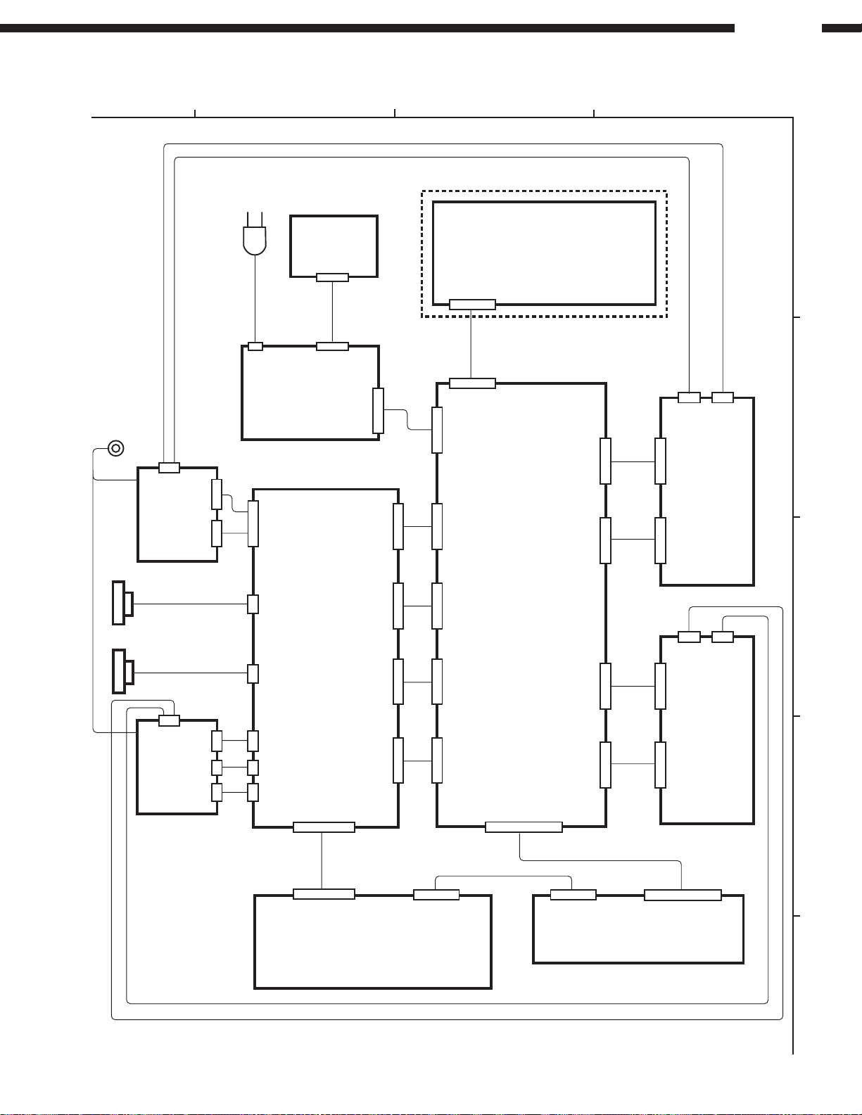
AC CORD
GU-3461-8
ACD 780
(Option)
GU-3461-3
POWER UNIT
GU-3461-1
CONTROL UNIT
C.MECHA
A
C.MECHA
B
GU-3461-5
GU-3461-4
GU-3462-1
AUDIO UNIT
GU-3462-2
AUDIO UNIT A
GU-3462-3
AUDIO UNIT B
GU-3461-7
GU-3461-6
DISPLAY UNIT
CW091
9P
CY156 15P
CX156 15P
CY121 12PCX121 12P
CY123 12PCX123 12P
CY124 12PCX124 12P
CY122 12P
CX127 12P CY127 12P
CX128 12P
CX129 12P CY129 12P
CX126 12P CY126 12P
CY128 12P
CY0363PCY034
3P
CY0353PCY033
3P
CX122 12P
CX062 6P
CX041 4P
CX071 7P
CX061 6P
CX051 5P
CY061 6P
CY051 5P
CX171 17P
CX173 17P
CY173 17P CY125 12P CX125 12P
CX252 25P
CY252 25P
CX155 15P
CY155 15P
CX091 9PCX021
2P
WIRING DIAGRAM
DN-780R
1
32
4
A
B
C
D
E
42

SCHEMATIC DIAGRAMS (1/7)
1 2 3 4 5 6 7 8 9 10 11
DN-780R
A
B
C
D
E
_
+
B LINE
SIGNAL LINE
NOTICE
ALL RESISTANCE VALUES IN OHM. k=1,000 OHM M=1,000,000 OHM
ALL CAPACITANCE VALUES IN MICRO FARAD. P=MICRO-MICRO FARAD
EACH VOLTAGE AND CURRENT ARE MEASUERD AT MO SIGNAL INPUT
CONDITION.
CIRCUIT AND PARTS ARE SUBJECT TO CHANGE WITHOUT PRIOR
NOTICE.
WARNING:
Parts marked with this symbol have critical characteristics.
Use ONLY replacement parts recommended by the manufacture.
CAUTION:
Before returning the unit to the customer, make sure you make either (1) a
leakage current check or (2) a line to chassis resistance check. If the leakage
current exceeds 0.5 milliamps, or if the resistance from chassis to either side
of the power card is less than 460kohms, the unit is defective.
WARNING:
DO NOT return the unit to the customer until the problem is located and
corrected.
SCHEMATIC DIAGRAMS (1/7)
GU-3461-1 CONTROL UNIT
F
G
H
43

SCHEMATIC DIAGRAMS (2/7)
1 2 3 4 5 6 7 8 9 10 11
DN-780R
A
B
C
D
E
_
+
B LINE
SIGNAL LINE
WARNING:
Parts marked with this symbol have critical characteristics.
Use ONLY replacement parts recommended by the manufacture.
CAUTION:
Before returning the unit to the customer, make sure you make either (1) a
leakage current check or (2) a line to chassis resistance check. If the leakage
current exceeds 0.5 milliamps, or if the resistance from chassis to either side
of the power card is less than 460kohms, the unit is defective.
WARNING:
DO NOT return the unit to the customer until the problem is located and
corrected.
NOTICE
ALL RESISTANCE VALUES IN OHM. k=1,000 OHM M=1,000,000 OHM
ALL CAPACITANCE VALUES IN MICRO FARAD. P=MICRO-MICRO FARAD
EACH VOLTAGE AND CURRENT ARE MEASUERD AT MO SIGNAL INPUT
CONDITION.
CIRCUIT AND PARTS ARE SUBJECT TO CHANGE WITHOUT PRIOR
NOTICE.
SCHEMATIC DIAGRAMS (2/7)
GU-3461-2 DISPLAY UNIT
GU-3461-3 POWER UNIT
GU-3461-4 SWA UNIT
GU-3461-5 SWB UNIT
GU-3461-8 POWER UNIT2
F
G
H
44

SCHEMATIC DIAGRAMS (3/7)
1 2 3 4 5 6 7 8 9 10 11
DN-780R
A
B
C
D
E
_
+
B LINE
SIGNAL LINE
NOTICE
ALL RESISTANCE VALUES IN OHM. k=1,000 OHM M=1,000,000 OHM
ALL CAPACITANCE VALUES IN MICRO FARAD. P=MICRO-MICRO FARAD
EACH VOLTAGE AND CURRENT ARE MEASUERD AT MO SIGNAL INPUT
CONDITION.
CIRCUIT AND PARTS ARE SUBJECT TO CHANGE WITHOUT PRIOR
NOTICE.
WARNING:
Parts marked with this symbol have critical characteristics.
Use ONLY replacement parts recommended by the manufacture.
CAUTION:
Before returning the unit to the customer, make sure you make either (1) a
leakage current check or (2) a line to chassis resistance check. If the leakage
current exceeds 0.5 milliamps, or if the resistance from chassis to either side
of the power card is less than 460kohms, the unit is defective.
WARNING:
DO NOT return the unit to the customer until the problem is located and
corrected.
SCHEMATIC DIAGRAMS (3/7)
GU-3461-7 MIC UNIT
F
G
H
45

SCHEMATIC DIAGRAMS (4/7)
1 2 3 4 5 6 7 8 9 10 11
DN-780R
A
B
C
D
E
NOTICE
ALL RESISTANCE VALUES IN OHM. k=1,000 OHM M=1,000,000 OHM
ALL CAPACITANCE VALUES IN MICRO FARAD. P=MICRO-MICRO FARAD
EACH VOLTAGE AND CURRENT ARE MEASUERD AT MO SIGNAL INPUT
CONDITION.
CIRCUIT AND PARTS ARE SUBJECT TO CHANGE WITHOUT PRIOR
NOTICE.
WARNING:
Parts marked with this symbol have critical characteristics.
Use ONLY replacement parts recommended by the manufacture.
CAUTION:
Before returning the unit to the customer, make sure you make either (1) a
leakage current check or (2) a line to chassis resistance check. If the leakage
current exceeds 0.5 milliamps, or if the resistance from chassis to either side
of the power card is less than 460kohms, the unit is defective.
WARNING:
DO NOT return the unit to the customer until the problem is located and
corrected.
SCHEMATIC DIAGRAMS (4/7)
GU-3462-1 AUDIO UNIT
GU-3462-2 AUDIO UNIT [A DECK]
_
+
B LINE
SIGNAL LINE
F
G
H
46

SCHEMATIC DIAGRAMS (5/7)
1 2 3 4 5 6 7 8 9 10 11
DN-780R
A
B
C
D
E
_
+
B LINE
SIGNAL LINE
NOTICE
ALL RESISTANCE VALUES IN OHM. k=1,000 OHM M=1,000,000 OHM
ALL CAPACITANCE VALUES IN MICRO FARAD. P=MICRO-MICRO FARAD
EACH VOLTAGE AND CURRENT ARE MEASUERD AT MO SIGNAL INPUT
CONDITION.
CIRCUIT AND PARTS ARE SUBJECT TO CHANGE WITHOUT PRIOR
NOTICE.
WARNING:
Parts marked with this symbol have critical characteristics.
Use ONLY replacement parts recommended by the manufacture.
CAUTION:
Before returning the unit to the customer, make sure you make either (1) a
leakage current check or (2) a line to chassis resistance check. If the leakage
current exceeds 0.5 milliamps, or if the resistance from chassis to either side
of the power card is less than 460kohms, the unit is defective.
WARNING:
DO NOT return the unit to the customer until the problem is located and
corrected.
SCHEMATIC DIAGRAMS (5/7)
GU-3462-1 AUDIO UNIT
GU-3462-3 AUDIO UNIT [B DECK]
F
G
H
47

SCHEMATIC DIAGRAMS (6/7)
1 2 3 4 5 6 7 8 9 10 11
DN-780R
A
B
C
D
E
NOTICE
ALL RESISTANCE VALUES IN OHM. k=1,000 OHM M=1,000,000 OHM
ALL CAPACITANCE VALUES IN MICRO FARAD. P=MICRO-MICRO FARAD
EACH VOLTAGE AND CURRENT ARE MEASUERD AT MO SIGNAL INPUT
CONDITION.
CIRCUIT AND PARTS ARE SUBJECT TO CHANGE WITHOUT PRIOR
NOTICE.
WARNING:
Parts marked with this symbol have critical characteristics.
Use ONLY replacement parts recommended by the manufacture.
CAUTION:
Before returning the unit to the customer, make sure you make either (1) a
leakage current check or (2) a line to chassis resistance check. If the leakage
current exceeds 0.5 milliamps, or if the resistance from chassis to either side
of the power card is less than 460kohms, the unit is defective.
WARNING:
DO NOT return the unit to the customer until the problem is located and
corrected.
SCHEMATIC DIAGRAMS (6/7)
GU-3462-1 AUDIO UNIT
_
+
B LINE
SIGNAL LINE
F
G
H
48

SCHEMATIC DIAGRAMS (7/7)
1 2 3 4 5 6 7 8 9 10 11
DN-780R
A
B
C
D
E
_
+
B LINE
SIGNAL LINE
NOTICE
ALL RESISTANCE VALUES IN OHM. k=1,000 OHM M=1,000,000 OHM
ALL CAPACITANCE VALUES IN MICRO FARAD. P=MICRO-MICRO FARAD
EACH VOLTAGE AND CURRENT ARE MEASUERD AT MO SIGNAL INPUT
CONDITION.
CIRCUIT AND PARTS ARE SUBJECT TO CHANGE WITHOUT PRIOR
NOTICE.
WARNING:
Parts marked with this symbol have critical characteristics.
Use ONLY replacement parts recommended by the manufacture.
CAUTION:
Before returning the unit to the customer, make sure you make either (1) a
leakage current check or (2) a line to chassis resistance check. If the leakage
current exceeds 0.5 milliamps, or if the resistance from chassis to either side
of the power card is less than 460kohms, the unit is defective.
WARNING:
DO NOT return the unit to the customer until the problem is located and
corrected.
SCHEMATIC DIAGRAMS (7/7)
GU-3463 XLR UNIT
(ACD-780:Option)
F
G
H
49

Ver 1.00
1 page of 30
Specification
for
Serial Interface DN-780R
Denon, Ltd.

Ver 1.00
2 page of 30
Contents
1 SERIAL COMMUNICATION INTERFACE..........................................................................3
PHYSICAL INTERFACE
1.1
TRANSFER FORMAT OF SERIAL DATA
1.2
COMMAND FORMAT AND ANSWER FORMAT
1.3
PROTOCOL FOR DATA TRANSMISSION AND RECEPTION
1.4
1.4.1 Basic procedure..............................................................................................................4
1.4.2 Communication errors...................................................................................................5
COMMAND
1.5
LIST OF COMMAND CODES
1.6
LIST OF ANSWER CODES
1.7
LIST OF STATUS CODES
1.8
COMMAND SPECIFICATION
1.9
NSWER SEQUENCE
/ A
1.9.1 Reset .............................................................................................................................11
1.9.2 Request Play Status ....................................................................................................12
1.9.3 Request CPU Version ..................................................................................................13
1.9.4 Request Tape Status....................................................................................................14
1.9.5 Request Establish ........................................................................................................15
1.9.6 Request Machine ID ....................................................................................................16
1.9.7 Play...............................................................................................................................17
1.9.8 Stop...............................................................................................................................18
1.9.9 Record...........................................................................................................................19
1.9.10 Pause ..........................................................................................................................20
1.9.11 Forward ......................................................................................................................21
1.9.12 Rewind........................................................................................................................22
1.9.13 Direction.....................................................................................................................23
1.9.14 Memory.......................................................................................................................24
1.9.15 Counter Reset ............................................................................................................25
1.9.16 Dolby...........................................................................................................................26
1.9.17 Twin Record ...............................................................................................................27
1.9.18 Dubbing ......................................................................................................................28
1.9.19 Speed ..........................................................................................................................29
1.9.20 Setting ........................................................................................................................30
.............................................................................................................3
.......................................................................................3
..............................................................................4
............................................................4
............................................................................................6
......................................................................................................9
........................................................................................................10
.........................................................................................................10
...................................................................................................11
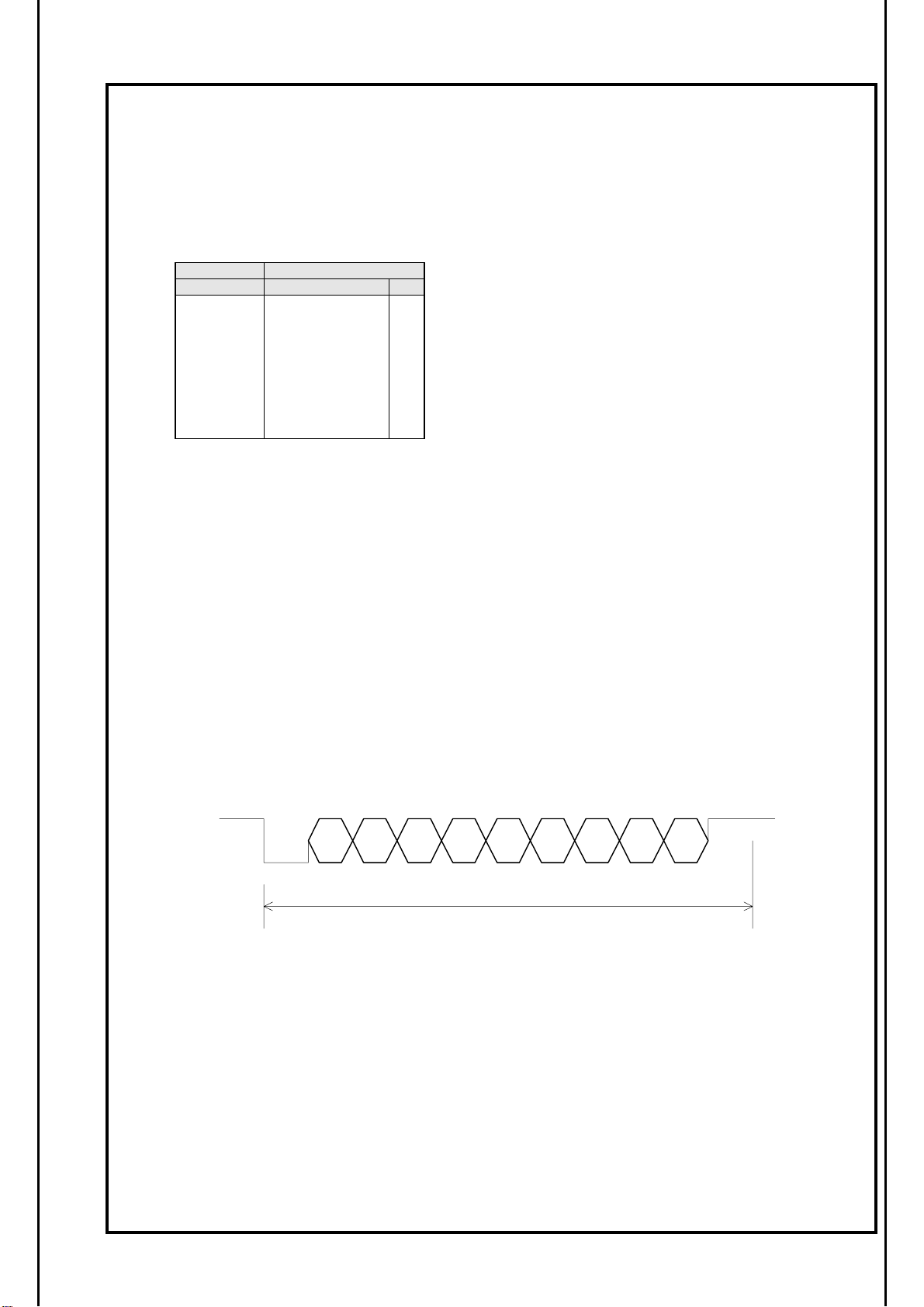
Ver 1.00
3 page of 30
1
Serial communication interface
1.1 Physical interface
Arrangement of connector signals
RS-232C
Terminal # Signal I/O
1 NC
2 TxD O
3 RxD I
4 NC
5 S.GROUND
6 NC
7 NC
8 NC
9 NC
−
−
−
−
−
−
−
1.2 Transfer format of serial data
- Interface
- Communication system
- Data transfer mode
- Transfer rate
- Start bit ( ST )
- Data bit ( b0-b7 )
- Parity ( P )
- Stop bit ( SP )
- Transfer data
- Control characters
:
RS-232C
:
Half-duplex communication
:
Start stop synchronization
:
9,600bps
:
1 bit
:
8 bits
:
Even number
:
1 bit
:
ASCII code
:
STX (02h)
ETX (03h)
NAK (15h)
ACK (06h)
ST SPb0 b1 b2 b3 b4 b5 b6 b7 P
11/9600(sec
)

Ver 1.00
4 page of 30
1.3 Command format and answer format
The commands and answers consist of command code (CC) , parameter codes (PC) and some control
codes. The commands are transmitted from the host to the device and answers are transmitted from
the device to the host. The host and device shall be designed to send and receive block check
characters ( BCC ) to check the completion of command transport.
Here are the formats.
Commands :<STX> <CC> <PC0> <PC1> <PC2> <-----> <PCn> <ETX> <BCCH><BCCL>
STX(Start of TeXt)
CC(Command Code)
PC(Parameter Code)
( contents and number of parameters )
ETX(End of TeXt)
BCC(Block Check Character)
CC + PC0 + PC1 + PC2 + ----- + PCn + ETX = Xyh
(Each of X and Y is 4 bit long ) X , Y=0,1,2,3,4,5,6,7,8,9,A,B,C,D,E,F
BCCH ( high-level byte ) = X as converted to an ASCII code
BCCL ( low-level byte ) = Y as converted to an ASCII code
Answers:<STX> <CC> <AC> <PC0> <PC1> <PC2> <-----> <PCn> <ETX><BCCH><BCCL>
STX(Start of TeXt)
RC(Reply Code)
AC(Answer Code)
PC(Parameter Code)
( contents and number of parameters )
ETX(End of TeXt)
BCC(Block Check Character)
CC + PC0 + PC1 + PC2 + ----- + PCn + ETX = Xyh
(Each of X and Y is 4 bit long) X , Y=0,1,2,3,4,5,6,7,8,9,A,B,C,D,E,F
BCCH ( high-level byte ) = X as converted to an ASCII code
BCCL ( low-level byte ) = Y as converted to an ASCII code
:
:
:
:
:
02h
:
Command code
:
Defined for each command
03h
:
:
02h
Reply code(=Command code)
Answer code
:
Defined for each command
03h
:
1.4 Protocol for data transmission and reception
This device is based on half-duplex communication. The unit shall therefore transmit commands and
receive answers according to the following procedure.
1.4.1 Basic procedure
a) The host shall select commands for this device and transmit them to this unit.0
b) After sending a command, the host shall receive an answer from this device, then send the next
command.
c) The host shall analyze the RC, AC, and PC in answers and decide whether command has been
executed.
d) To get more information after received an answer, the host can send a status request command.
e) The time from the start of command transmission to the end should be max 40 msec.
f) The time from the completion of command transmission to the start of answer-back is 5 sec max.

Ver 1.00
5 page of 30
g) This device cannot receive any commands for about 1.8seconds after the power switch is turned
on.
1.4.2 Communication errors
a) When detect communication error such as overrun, framing, or parity error during receive a
command, this device shall give NAK ( 15h ) within 80ms from the start of command transmission .
b) If the host has received NAK from this device, it shall retransmit the command that it has
transmitted immediately beforehand.
c) When detect communication error such as overrun, framing, or parity error during receive a
answer, the host shall give NAK ( 15h ) within 80ms from the start of command transmission .
d) If it has received NAK from the host, this device shall retransmit the answer it has transmitted
immediately beforehand. ( MAX 40ms)
e) When there is no answer from the unit within 80 ms, the host shall retransmit the command.

Ver 1.00
CC
A
A
RC
6 page of 30
1.5 Command / Answer sequence
Shown below are the command sequence and the answer sequence of this device.
a) When a command is normally receivedand an answer is normally received with an answer
parameter
Comand Transmitted
MAX
40ms
HOST
DEVICE
STX
CC
PC0
PC1
PC2
PCn
ETX
BCC
Error Check OK
Error Check OK
Next Command
Transmitted
STX
PC0
PC1
PCn
ETX
BCC
STX
PC0
MAX
60ms
C
nswer Transmietted

Ver 1.00
7 page of 30
b) When a command is abnormally received ( with or without an answer parameter )
Command Transmitted
MAX
40ms
Command Retransmitted
HOST UNIT
STX
CC
PC0
PC1
PC2
PCn
ETX
BCC
NAK
STX
CC
PC0
Error Check NG
NAK return
MAX
MAX
100ms
80ms

Ver 1.00
8 page of 30
c) When a command with an answer parameter is normally received ( unit ) and an answer is
abnormally received ( host )
Command Transmitted
MAX
40ms
HOST UNIT
STX
CC
PC0
PC1
PC2
PCn
ETX
BCC
STX
RC
AC
PC0
PC1
Error Check OK
MAX
MAX
40ms
60ms
Answer Transmitted
Error Check NG
PCn
ETX
BCC
NAK
STX
RC
AC
PC0
PC1
MAX
MAX
40ms
60ms
Answer
Retransmitted

Ver 1.00
9 page of 30
1.6 List of command codes
Here is a list of command code types.
2Xh :Reset command
3Xh :Command related to the acquisition of device information ( such as status and
name )
4Xh :Operation instruction command to the device
No. Command Code(ASCII) Operation
Reset 20h([SP]) Reset request
1
Request Play Status 30h(0) Acquires system status ( such as the entire device ).
2
Request CPU Version 31h(1) Acquires the CPU version.
3
Request Tape Status 32h(2) Acquires the cassette tape status.
4
Request Establish 33h(3) Acquires the setup contents(such as switch position
5
Request Machine ID 34h(4) Acquires the machine ID.
6
Play 40h Starts playback or recording.
7
Stop 41h Stops playback or recording.
8
REC 42h Requests recording pause and recording mute.
9
Pause 43h Requests recording pause.
10
Forward 44h Fast forward
11
Rewind 45h Rewind
12
Direction 46h Changes the tape transport direction.
13
Memory 47h Switch over the counter memory ON/OFF.
14
Counter Reset 48h Reset tape counter
15
Dolby 49h Dolby setting
16
Twin REC 4Ah Twin recording
17
Dubbing 4Bh Dubbing
18
Speed 4Ch Setting of tape transport speed
19
Setting 4Dh Setting of reverse mode
20
and mode select).

Ver 1.00
10 page of 30
1.7 List of answer codes
No. Status Code(ASCII) Description
Command OK 20h(SP) Accepts the command.
1
Invalid 30h(0) Invalid command.
2
Format Error 31h(1) Inappropriate command format.
3
CONDITION ERROR 32h(2) Can not process, because of inhibited condition .
4
1.8 List of status codes
Here is a list of answer code types.
3Xh:Status of the entire system
4Xh:Status of A Mecha / B Mecha
No. Status Code(ASCII) Description
Normal 31h(1) Normal mode
1
Twin REC 32h(2) Under twin recording.
2
Dubbing 33h(3) Under dubbing.
3
No Tape 41h(A) No cassette tape.
4
Stop 42h(B) Under stop.
5
Play 43h(C) Under playback.
6
REC Pause 44h(D) Under recording pause.
7
Recording 45h(E) Under recording.
8
REC Mute 46h(F) Under recording mute.
9
Forward 47h(G) Under fast forward.
10
Rewind 48h(H) Under rewind.
11
Cue 49h(I) Under cue.
12
Review 4ah(J) Under review.
13
Play Mute 4bh(K) Under play mute (review after music search)
14

Ver 1.00
11 page of 30
1.9 Command specification
1.9.1 Reset
When the device received this command, clear all of conditions and restarts same as power ON.
byte\bit
0
1
2 Reserve( 00h )
3 Reserve( 00h )
4 Reserve( 00h )
5 Reserve( 00h )
6 ETX( 03h )
7 BCCH( high-level )
8 BCCL( low-level )
a) Answers returned
-None.
b) Special condition
-This device cannot receive any commands for about 1.8seconds after the this command is
sent.
7 6 5 4 3 2 1 0
STX( 02h )
Command code( ‘ SP ‘ )

Ver 1.00
12 page of 30
1.9.2 Request Play Status
This command requests the cassette deck playing information.
byte\bit
0
1
2
3
4
5
6
7
8
a) Answers returned
byte\bit
0
1
2
3
4
5
6
7 A Mecha tape counter 1000 digit ( ‘ 0,1,2---8,9 ‘ )
8 A Mecha tape counter 100 digit ( ‘ 0,1,2---8,9 ‘ )
9 A Mecha tape counter 10 digit ( ‘ 0,1,2---8,9 ‘)
10 A Mecha tape counter 1 digit ( ‘ 0,1,2---8,9 ‘)
11 B Mecha status
12
13 B Mecha tape counter 1000 digit ( ‘ 0,1,2---8,9 ‘)
14 B Mecha tape counter 100 digit( ‘ 0,1,2---8,9 ‘)
15 B Mecha tape counter 10 digit ( ‘ 0,1,2---8,9 ‘)
16 B Mecha tape counter 1 digit ( ‘ 0,1,2---8,9 ‘)
17 ETX ( 03h )
18 BCCH( high-level )
19 BCCH( low-level )
(*1) Tape speed
CODE TAPE SPEED
30h(0) Normal speed
31h(1) High speed (x2)
b) Special condition
- Tape speed information is only valid with “Twin REC Status (32h)”, and “Dubbing Status
(33h)”. Ignore this information with another status.
7 6 5 4 3 2 1 0
STX( 02h )
Command code (‘ 0 ‘)
Reserve( 00h )
Reserve( 00h )
Reserve( 00h )
Reserve( 00h )
ETX( 03h )
BCCH( high-level )
BCCL( low-level )
7 6 5 4 3 2 1 0
STX( 02h )
Reply code (‘ 0 ‘)
Answer code
System status
Tape speed ( *1 )
A Mecha status
Mark ‘−’ or ‘ ‘
Mark’−’or’ ‘

Ver 1.00
13 page of 30
1.9.3 Request CPU Version
This command requests the CPU version .
byte\bit
0
1
2
3
4
5
6
7
8
a) Answers returned
byte\bit
0
1
2
3
4
5
6
7 ETX( 03h )
8 BCCH( high-level )
9 BCCL( low-level )
b) Special conditions
- None.
7 6 5 4 3 2 1 0
STX( 02h )
Command code ( ‘ 1 ‘ )
Reserve( 00h )
Reserve( 00h )
Reserve( 00h )
Reserve( 00h )
ETX( 03h )
BCCH( high-level )
BCCL( low-level )
7 6 5 4 3 2 1 0
STX( 02h )
Reply code ( ‘ 1 ‘ )
Answer code
CPU version No. 1000 digit (ASCII)
CPU version No. 100 digit (ASCII)
CPU version No. 10 digit (ASCII)
CPU version No. 1 digit (ASCII)

Ver 1.00
14 page of 30
1.1.1 Request Tape Status
This command requests condition of the loaded tapes .
byte\bit
0
1
2
3
4
5
6
7
8
a) Answers returned
byte\bit
0
1
2
3
4
5
6 BCCH( high-level )
7 BCCL( low-level)
(*1)Tape status
CODE TAPE STATUS
30h(0) No tape
31h(1) A and B side of the tape can record.
32h(2) A side of the tape can not record.
33h(3) A side of the tape can record.
34h(4) A and B side of the tape can not record.
b) Special conditions
- None
7 6 5 4 3 2 1 0
STX( 02h )
Command code ( ‘ 2 ‘ )
Reserve ( 00h )
Reserve ( 00h )
Reserve ( 00h )
Reserve ( 00h )
ETX( 03h )
BCCH( high-level )
BCCL( low-level )
7 6 5 4 3 2 1 0
STX( 02h )
Reply code ( ‘ 2 ‘ )
Answer code
ETX( 03h )
A Mecha tape status (*1)
B Mecha tape status (*1)
B side of the tape can record.
B side of the tape can not record.

Ver 1.00
15 page of 30
1.9.5 Request Establish
This command requests
byte\bit
a) Answers returned
byte\bit
10
11 ETX( 03h )
12 BCCH( high-level )
13 BCCL( low-level )
(*1)
DUPULICATE MODE (*3) Dolby
CODE DUPULICATE MODE CODE DOLBY
30h(0) OFF 30h(0) OFF
31h(1) MASTER 31h(1) B
32h(2) SLAVE 32h(2) C
(*2) REVERSE MODE (*4) Direction
CODE REVERSE MODE CODE DIRECTION
30h(0) Single 30h(0) Forward
31h(1) Loop 31h(1) Reverse
32h(2) Relay (*5) Memory
33h(3) Cascade CODE MEMORY
the setup contents (such as switch position and mode select).
7 6 5 4 3 2 1 0
0
1
2
3
4
5
6
7
8
7 6 5 4 3 2 1 0
0
1
2
3
4
5
6
7
8
9
DUPULICATE MODE (*1)
STX( 02h )
Command code ( ‘ 3 ‘ )
Reserve ( 00h )
Reserve ( 00h )
Reserve ( 00h )
Reserve ( 00h )
ETX( 03h )
BCCH( high-level )
BCCL( low-level )
STX( 02h )
Reply code ( ‘ 3 ‘ )
Answer code
REVERSE MODE (*2)
A Mecha Dolby (*3)
A Mecha Direction (*4)
A Mecha Memory (*5)
B Mecha Dolby (*4)
B Mecha Direction (*5)
B Mecha Memory (*6)
30h(0) OFF
31h(1) ON
b) Special conditions
After the device received Dolby setting command (49h), the Dolby information in this
-
answer and device’s panel setting may be different.

Ver 1.00
16 page of 30
1.9.6 Request Machine ID
This command requests
the machine ID.
byte\bit
0
1
2
3
4
5
6
7
8
7 6 5 4 3 2 1 0
STX( 02h )
Command code ( ‘ 4 ‘ )
Reserve ( 00h )
Reserve ( 00h )
Reserve ( 00h )
Reserve ( 00h )
ETX( 03h )
BCCH( high-level )
BCCL( low-level )
a) Answers returned
byte\bit
0
1
2
3〜15
16 ETX( 03h )
17 BCCH( high-level )
18 BCCL( low-level )
7 6 5 4 3 2 1 0
STX( 02h )
Reply code ( ‘ 4 ‘ )
Answer code
Machine ID
“ DENON DN-780R “ (ASCII)
b) Special conditions
- None.

Ver 1.00
17 page of 30
1.9.7 Play
The device starts playback when device is not recording related status, and starts recording only
from Rec Pause or Rec Mute. Rec Pause means pausing (standby) for record. Rec Mute is muted
recording of 5 sec to make time to music record.
byte\bit
0
1
2
3
4
5
6
7
8
a) Answers returned
byte\bit
0
1
2
3
4
5
b) Special conditions
- When mecha status is REC pause (44h) or REC mute (46h), the device will start recording.
- The answer code returns “Command OK” , when mecha status data is Play (43h) or
Recording (45h).
- When mecha status data is No Tape (41h), this device returns “CONDITION ERROR” .
- This command force to start playback , when mecha status is Stop (42h) , Forward (47h),
Rewind (48h), Cue (49h), Review (4ah), or Play Mute (4bh).
7 6 5 4 3 2 1 0
STX( 02h )
Command code ( ‘ @ ‘ )
Deck mecha ( A Mecha:’ 0 ‘or B Mecha:’ 1 ‘)
Reserve ( 00h )
Reserve ( 00h )
Reserve ( 00h )
ETX( 03h )
BCCH( high-level )
BCCL( low-level )
7 6 5 4 3 2 1 0
STX( 02h )
Reply code ( ‘ @ ‘ )
Answer code
ETX( 03h )
BCCH( high-level )
BCCL( low-level )

Ver 1.00
18 page of 30
1.9.8 Stop
This command stops playback, recording, fast forward and rewind.
byte\bit
0
1
2
3
4
5
6
7
8
a) Answers returned
byte\bit
0
1
2
3
4
5
b) Special conditions
- The answer code returns “Command OK” , when mecha status data is Stop (42h).
- The answer code returns “Command OK” , when mecha status data is No Tape (41h) .
7 6 5 4 3 2 1 0
STX( 02h )
Command code (‘ A ‘)
Deck mecha ( A Mecha:’ 0 ‘or B Mecha:’ 1 ‘)
Reserve ( 00h )
Reserve ( 00h )
Reserve ( 00h )
ETX( 03h )
BCCH( high-level )
BCCL( low-level )
7 6 5 4 3 2 1 0
STX( 02h )
Reply code (‘ A ‘)
Answer code
ETX( 03h )
BCCH( high-level )
BCCL( low-level )

Ver 1.00
19 page of 30
1.9.9 REC
This command operations only REC Pause and REC Mute .
byte\bit
0
1
2
3
4
5
6
7
8
a) Answers returned
byte\bit
0
1
2
3
4
5
b) Special conditions
- The device returns “Condition Error” status , when mecha status data is No Tape (41h), Play
(43h) , Forward (47h), Rewind (48h), Cue (49h), Review (4ah), or Play Mute (4bh).
- This command makes Rec Pause (Rec-Standby) , when mecha status is Stop (42h).
- This command makes another 5 sec muted recording, when mecha status data is REC Pause
(44h), REC(45h), REC Mute (46h). After Rec Mute, the device will change Rec Pause.
- The answer code returns “Condition Error” , when the tape is inhibited recording.
7 6 5 4 3 2 1 0
STX( 02h )
Command code (‘ B ‘)
Deck mecha ( A Mecha:’ 0 ‘or B Mecha:’ 1 ‘)
Reserve ( 00h )
Reserve ( 00h )
Reserve ( 00h )
ETX( 03h )
BCCH( high-level )
BCCL( low-level )
7 6 5 4 3 2 1 0
STX( 02h )
Reply code (‘ B ‘)
Answer code
ETX( 03h )
BCCH( high-level )
BCCL( low-level )

Ver 1.00
20 page of 30
1.9.10 Pause Recording
This command pauses recording.
byte\bit
0
1
2
3
4
5
6
7
8
a) Answers returned
byte\bit
0
1
2
3
4
5
b) Special condition
- This command is valid, when REC(45h) and REC Mute (46h).
- When REC Mute, the device will stop muted recording right now and change to REC Pause.
7 6 5 4 3 2 1 0
STX( 02h )
Command code (‘ C ‘)
Deck mecha ( A Mecha:’ 0 ‘or B Mecha:’ 1 ‘)
Reserve ( 00h )
Reserve ( 00h )
Reserve ( 00h )
ETX( 03h )
BCCH( high-level )
BCCL( low-level )
7 6 5 4 3 2 1 0
STX( 02h )
Reply code (‘ C ‘)
Answer code
ETX( 03h )
BCCH( high-level )
BCCL( low-level )

Ver 1.00
21 page of 30
1.9.11 Forward
The device starts fast forward (right direction of tape). Note that this command’s direction and
real sound direction is sometime different. If DIRECTION of Requests Establish is Forward, both
directions are same and if REVERSE, the directions are different and this command makes rewind
function.
byte\bit
0 STX(02h)
1
2
3
4
5
6 ETX(03h)
7
8
7 6 5 4 3 2 1 0
Command code ( ‘D’ )
Deck mecha ( A Mecha:’ 0 ‘or B Mecha:’ 1 ‘)
Music search ON/OFF ( OFF:’ 0 ‘or ON:’ 1 ‘)
Reserve (00h)
Reserve (00h)
BCCH (high-level)
BCCL (low-level)
a) Answers returned
byte\bit
0
1
2
3
4
5
7 6 5 4 3 2 1 0
STX(02h)
Reply code ( ‘D’ )
Answer code
ETX(03h)
BCCH (high-level)
BCCL (low-level)
b) Special condition
- This command is not valid, when system status is Twin REC (32h) or Dubbing (33h).
(The answer code returns “CONDITION ERROR”.)
- The answer code returns “CONDITION ERROR” , when mecha status data is No Tape (41h).
- This command is valid, when Stop (42h), Play (43h) , REC Pause (44h), REC (45h), REC
Mute (46h), Forward (47h), Rewind (48h), Cue (49h), Review (4ah), or Play Mute (4bh).
- When the Direction information for Request Establish command is Reverse, this commands
makes rewind function.
- When Music search byte of this command is ON, the device starts to detect the next songs
starting point. After music search the device changes to playback.
.

Ver 1.00
22 page of 30
1.9.12 Rewind
The device starts rewind (left direction of tape). Note that this command’s direction and real
sound direction is sometime different. If DIRECTION of Requests Establish is Forward, both
directions are same and if REVERSE, the directions are different and this command makes fast
forward function.
byte\bit
0 STX(02h)
1
2
3
4
5
6 ETX(03h)
7
8
7 6 5 4 3 2 1 0
Command code ( ‘E’ )
Deck mecha ( A Mecha:’ 0 ‘or B Mecha:’ 1 ‘)
Music search ON/OFF ( OFF:’ 0 ‘or ON:’ 1 ‘)
Reserve (00h)
Reserve (00h)
BCCH (high-level)
BCCL (low-level)
a) Answers returned
byte\bit
0
1
2
3
4
5
7 6 5 4 3 2 1 0
STX(02h)
Reply code ( ‘E’ )
Answer code
ETX(03h)
BCCH (high-level)
BCCL (low-level)
b) Special condition
- This command is not valid, when system status is Twin REC (32h) or Dubbing (33h).
(The answer code returns “CONDITION ERROR”.)
- The answer code returns “CONDITION ERROR” , when mecha status data is No Tape (41h).
- This command is valid, when Stop (42h), Play (43h) , REC Pause (44h), REC (45h), REC
Mute (46h), Forward (47h), Rewind (48h), Cue (49h), Review (4ah), or Play Mute (4bh).
- When the Direction information for Request Establish command is Reverse, this commands
makes fast forward function.
- When Music search byte of this command is ON, the device starts to detect the next songs
starting point. After music search the device changes to playback.

Ver 1.00
23 page of 30
1.9.13 Direction
This command changes transport direction of the Tape.
byte\bit
0
1
2
3
4
5
6
7
8
a) Answers returned
byte\bit
0
1
2
3
4
5
b) Special condition
- This command is not valid, when system status is Dubbing (33h).
(The answer code returns “CONDITION ERROR”.)
- This command is valid, when system status is Twin REC (32h).
(mecha status is stop or REC Pause (44h) only)
- This command is valid, when mecha status data is not REC Mute (46h) or Play Mute (4bh).
7 6 5 4 3 2 1 0
STX( 02h )
Command code (‘ F ‘)
Deck mecha ( A Mecha:’ 0 ‘or B Mecha:’ 1 ‘)
Reserve (00h)
Reserve (00h)
Reserve (00h)
ETX( 03h )
BCCH( high-level )
BCCL( low-level )
7 6 5 4 3 2 1 0
STX( 02h )
Reply code (‘ F ‘)
Answer code
ETX( 03h )
BCCH( high-level )
BCCL( low-level )

Ver 1.00
24 page of 30
1.9.14 Memory
This selects Memory ON/OFF of counter.
byte\bit
0 STX( 02h )
1 Command code (‘ G ‘)
2
3
4 Reserve (00h)
5 Reserve (00h)
6 ETX( 03h )
7 BCCH( high-level )
8 BCCL( low-level )
a) Answers returned
byte\bit
0 STX( 02h )
1 Reply code (‘ G ‘)
2 Answer code
3 ETX( 03h )
4 BCCH( high-level )
5 BCCL( low-level )
7 6 5 4 3 2 1 0
Deck mecha ( A Mecha:’ 0 ‘or B Mecha:’ 1 ‘)
ON/OFF ( OFF:’ 0 ‘or ON:’ 1 ‘)
7 6 5 4 3 2 1 0
b) Special condition
- The command is valid always.

Ver 1.00
25 page of 30
1.9.15 Counter reset
This resets tape counter.
byte\bit
0 STX( 02h )
1 Command code (‘ H ‘)
2
3 Reserve (00h)
4 Reserve (00h)
5 Reserve (00h)
6 ETX( 03h )
7 BCCH( high-level )
8 BCCL( low-level )
a) Answers returned
byte\bit
0 STX( 02h )
1 Reply code (‘ H ‘)
2 Answer code
3 ETX( 03h )
4 BCCH( high-level )
5 BCCL( low-level )
7 6 5 4 3 2 1 0
Deck mecha ( A Mecha:’ 0 ‘or B Mecha:’ 1 ‘)
7 6 5 4 3 2 1 0
b) Special condition
- The command is valid always.

Ver 1.00
26 page of 30
1.9.16Dolby
This selects Dolby NR type.
byte\bit
0
1
2
3
4
5
6
7
8
( *1) Dolby
Code Dolby
30h (0) OFF
31h (1) Type B
32h (2) Type C
a) Answers returned
byte\bit
0
1
2
3
4
5
b) Special condition
- The command is valid always
.
7 6 5 4 3 2 1 0
STX( 02h )
Command code (‘ I ‘)
Deck mecha ( A Mecha:’ 0 ‘or B Mecha:’ 1 ‘)
Dolby (*1)
Reserve (00h)
Reserve (00h)
ETX( 03h )
BCCH( high-level )
BCCH ( low-level )
7 6 5 4 3 2 1 0
STX( 02h )
Reply code (‘ I ‘)
Answer code
ETX( 03h )
BCCH( high-level )
BCCH ( low-level )

Ver 1.00
27 page of 30
1.9.17 Twin REC
This prepares Twin REC.
byte\bit
0
1
2
3
4
5
6
7
8
a) Answers returned
byte\bit
0
1
2
3
4
5
b) Special condition
- This command is not valid, when system status is Twin REC (32h) or Dubbing (33h).
(The answer code returns “CONDITION ERROR”.)
- This command is valid, when A/B both mecha status data is Stop (42h) or REC Pause (44h).
- The answer code returns “CONDITION ERROR, when A/B both mecha status data is not
Stop (42h) or REC Pause (44h). (Duplicate mode is “OFF”)
- This command is valid, when A mecha status data is Stop (42h) and B mecha status data is
No Tape (41h), Stop (42h) or REC Pause (44h). (Duplicate mode is “MASTER”)
- This command is valid, when A mecha status data is Stop (42h) or REC Pause (44h) and B
mecha status data is No Tape (41h), Stop (42h) or REC Pause (44h). (Duplicate mode is
“SLAVE”)
7 6 5 4 3 2 1 0
STX( 02h )
Command code (‘ J ‘)
Reserve (00h)
Reserve (00h)
Reserve (00h)
Reserve (00h)
ETX( 03h )
BCCH( high-level )
BCCH ( low-level )
7 6 5 4 3 2 1 0
STX( 02h )
Reply code (‘ J ‘)
Answer code
ETX( 03h )
BCCH( high-level )
BCCH ( low-level )

Ver 1.00
28 page of 30
1.9.18 Dubbing
This starts dubbing.
byte\bit
0 STX( 02h )
1 Command code (‘ K ‘)
2 Tape speed (*1)
3 Reserve (00h)
4 Reserve (00h)
5 Reserve (00h)
6 ETX( 03h )
7 BCCH( high-level )
8 BCCH ( low-level )
( *1) Tape speed
Code Tape speed
30h (0) Normal speed
31h (1) High speed(x2)
a) Answers returned
byte\bit
0 STX(02h)
1 Reply code ( ‘ K ‘ )
2 Answer code
3 ETX( 03h )
4 BCCH( high-level )
5 BCCH ( low-level )
b) Special condition
- This command is not valid, when system status is Twin REC (32h) or Dubbing (33h).
(The answer code returns “CONDITION ERROR”.)
- This command is valid, when A/B both mecha status data is Stop (42h).
7 6 5 4 3 2 1 0
7 6 5 4 3 2 1 0

Ver 1.00
29 page of 30
1.9.19 Speed
This selects tape speed of Twin REC.
byte\bit
0 STX( 02h )
1 Command code (‘ L ‘)
2 Tape speed (*1)
3 Reserve (00h)
4 Reserve (00h)
5 Reserve (00h)
6 ETX( 03h )
7 BCCH( high-level )
8 BCCH ( low-level )
( *1) Tape speed
Code Tape speed
30h (0) Normal speed
31h (1) High speed(x2)
b) Answers returned
byte\bit
0 STX(02h)
1 Reply code ( ‘ 5 ‘ )
2 Answer code
3 ETX( 03h )
4 BCCH( high-level )
5 BCCH ( low-level )
b) Special condition
- This command is not valid, when system status is Normal (31h) or Dubbing (33h).
(The answer code returns “CONDITION ERROR”.)
- This command is valid, when system status is Twin REC and mecha status data is Stop
(42h) or REC Pause (44h).
- This command is valid only when Duplicate mode is “MASTER” or “SLAVE”.
7 6 5 4 3 2 1 0
7 6 5 4 3 2 1 0

Ver 1.00
30 page of 30
1.19.20 Setting
This sets Reverse mode.
byte\bit
0 STX( 02h )
1 Command code (‘ M ‘)
2 Reverse mode (*1)
3 Reserve (00h)
4 Reserve (00h)
5 Reserve (00h)
6 ETX( 03h )
7 BCCH( high-level )
8 BCCH ( low-level )
( *1) Reverse mode
Code Reverse mode
30h (0) Single
31h (1) Loop
32h (2) Relay
33h (3) Cascade
a) Answers returned
byte\bit
0 STX(02h)
1 Reply code ( ‘ M ‘ )
2 Answer code
3 ETX( 03h )
4 BCCH( high-level )
5 BCCH ( low-level )
b) Special condition
- This command is not valid, when system status is Twin REC (32h) or Dubbing (33h).
(The answer code returns “CONDITION ERROR”.)
- This command is valid, when Reverse mode is Relay (32h) or Cascade (33h) and A/B both
mecha status data is No Tape (41h) or Stop (42h).
7 6 5 4 3 2 1 0
7 6 5 4 3 2 1 0
 Loading...