


AV SURROUND RECEIVER
AVR-2805
OPERATING INSTRUCTIONS |
INSTRUCCIONES DE OPERACION |
||||||
BEDIENUNGSANLEITUNG |
GEBRUIKSAANWIJZING |
||||||
MODE D’EMPLOI |
BRUKSANVISNING |
||||||
ISTRUZIONI PER L’USO |
|
|
|
|
|
||
|
|
|
|
|
|
|
|
|
|
|
|
|
|
|
|
|
|
|
|
|
|
|
|
|
|
|
|
|
|
|
|
|
|
|
|
|
|
|
|
|
|
|
|
|
|
|
|
|
|
|
|
|
|
|
|
|
|
|
|
|
|
|
|
|
|
|
|
|
|
|
|
|
|
|
|
|
|
|
|
|
|
|
|
|
|
|
|
|
|
|
|
|
|
|
|
|
|
|
|
|
|
|
|
|
|
|
|
|
|
|
|
|
|
|
|
|
|
|
|
|
|
|
|
|
|
|
|
|
|
|
|
|
|
|
|
|
|
|
|
|
|
|
|
|
|
|
|
|
|
|
|
|
|
|
|
|
|
|
|
|
|
|
|
|
|
|
|
|
|
|
|
|
|
|
|
|
|
|
|
|
|
|
|
|
|
|
|
|
|
|
|
|
|
|
|
|
|
|
|
MASTER VOLUME
FUNCTION
SOURCE |
TUNING |
ZONE 2 / |
VIDEO |
|
PRESET |
REC SELECT |
SELECT |
ON / STANDBY
MODE |
ANALOG |
EXT. IN |
FOR ENGLISH READERS |
PAGE |
112 |
~ PAGE |
161 |
FÜR DEUTSCHE LESER |
SEITE |
162 |
~ SEITE |
120 |
POUR LES LECTEURS FRANCAIS |
PAGE |
121 |
~ PAGE |
179 |
PER IL LETTORE ITALIANO |
PAGINA |
180 |
~ PAGINA |
238 |
PARA LECTORES DE ESPAÑOL |
PAGINA |
239 |
~ PAGINA |
297 |
VOOR NEDERLANDSTALIGE LEZERS |
PAGINA |
298 |
~ PAGINA |
356 |
FOR SVENSKA LÄSARE |
SIDA |
357 |
~ SIDA |
415 |
ENGLISH DEUTSCH FRANCAIS ITALIANO ESPAÑOL NEDERLANDS SVENSKA
CAUTION
RISK OF ELECTRIC SHOCK
DO NOT OPEN
CAUTION: TO REDUCE THE RISK OF ELECTRIC SHOCK, DO
NOT REMOVE COVER (OR BACK). NO USER
SERVICEABLE PARTS INSIDE. REFER SERVICING
TO QUALIFIED SERVICE PERSONNEL.
The lightning flash with arrowhead symbol, within an equilateral triangle, is intended to alert the user to the presence of uninsulated “dangerous voltage” within the product’s enclosure that may be of sufficient magnitude to constitute a risk of electric shock to persons.
The exclamation point within an equilateral triangle is intended to alert the user to the presence of important operating and maintenance (servicing) instructions in the literature accompanying the appliance.
WARNING: TO REDUCE THE RISK OF FIRE OR ELECTRIC SHOCK, DO NOT EXPOSE THIS APPLIANCE TO RAIN OR MOISTURE.
• DECLARATION OF CONFORMITY |
• DECLARACIÓN DE CONFORMIDAD |
We declare under our sole responsibility that this |
Declaramos bajo nuestra exclusiva responsabilidad que |
product, to which this declaration relates, is in conformity |
este producto al que hace referencia esta declaración, |
with the following standards: |
está conforme con los siguientes estándares: |
EN60065, EN55013, EN55020, EN61000-3-2 and |
EN60065, EN55013, EN55020, EN61000-3-2 y EN61000- |
EN61000-3-3. |
3-3. |
Following the provisions of 73/23/EEC, 89/336/EEC and |
Siguiendo las provisiones de las Directivas 73/23/EEC, |
93/68/EEC Directive. |
89/336/EEC y 93/68/EEC. |
• ÜBEREINSTIMMUNGSERKLÄRUNG |
• EENVORMIGHEIDSVERKLARING |
Wir erklären unter unserer Verantwortung, daß dieses |
Wij verklaren uitsluitend op onze verantwoordelijkheid |
Produkt, auf das sich diese Erklärung bezieht, den |
dat dit produkt, waarop deze verklaring betrekking heeft, |
folgenden Standards entspricht: |
in overeenstemming is met de volgende normen: |
EN60065, EN55013, EN55020, EN61000-3-2 und |
EN60065, EN55013, EN55020, EN61000-3-2 en |
EN61000-3-3. |
EN61000-3-3. |
Entspricht den Verordnungen der Direktive 73/23/EEC, |
Volgens de bepalingen van de Richtlijnen 73/23/EEC, |
89/336/EEC und 93/68/EEC. |
89/336/EEC en 93/68/EEC. |
• DECLARATION DE CONFORMITE |
• ÖVERENSSTÄMMELSESINTYG |
Nous déclarons sous notre seule responsabilité que |
Härmed intygas helt på eget ansvar att denna produkt, |
l’appareil, auquel se réfère cette déclaration, est |
vilken detta intyg avser, uppfyller följande standarder: |
conforme aux standards suivants: |
EN60065, EN55013, EN55020, EN61000-3-2 och |
EN60065, EN55013, EN55020, EN61000-3-2 et |
EN61000-3-3. |
EN61000-3-3. |
Enligt stadgarna i direktiv 73/23/EEC, 89/336/EEC och |
D’après les dispositions de la Directive 73/23/EEC, |
93/68/EEC. |
89/336/EEC et 93/68/EEC. |
|
• DICHIARAZIONE DI CONFORMITÀ |
|
Dichiariamo con piena responsabilità che questo |
|
prodotto, al quale la nostra dichiarazione si riferisce, è |
|
conforme alle seguenti normative: |
|
EN60065, EN55013, EN55020, EN61000-3-2 e EN61000- |
|
3-3. |
|
In conformità con le condizioni delle direttive 73/23/EEC, |
|
89/336/EEC e 93/68/EEC. |
|
QUESTO PRODOTTO E’ CONFORME |
|
AL D.M. 28/08/95 N. 548 |
|
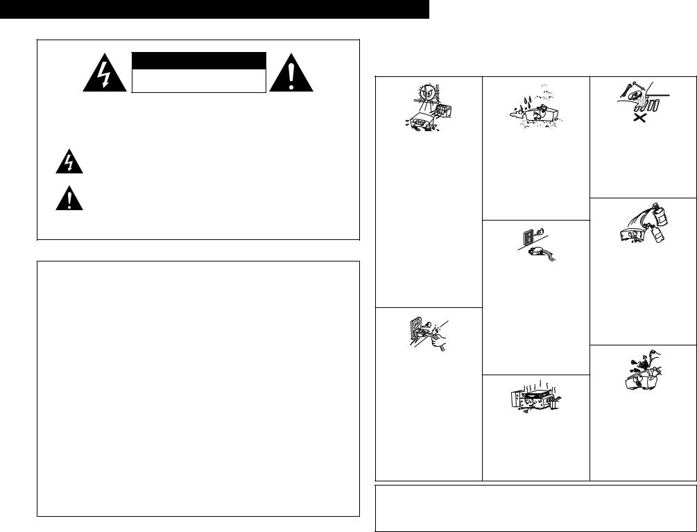
NOTE ON USE / HINWEISE ZUM GEBRAUCH /
OBSERVATIONS RELATIVES A L’UTILISATION / NOTE SULL’USO NOTAS SOBRE EL USO / ALVORENS TE GEBRUIKEN / OBSERVERA
•Avoid high temperatures.
Allow for sufficient heat dispersion when installed on a rack.
•Vermeiden Sie hohe Temperaturen. Beachten Sie, daß eine ausreichend Luftzirkulation gewährleistet wird, wenn das Gerät auf ein Regal gestellt wird.
•Eviter des températures élevées
Tenir compte d’une dispersion de chaleur suffisante lors de l’installation sur une étagère.
•Evitate di esporre l’unità a temperature alte. Assicuratevi che ci sia un’adeguata dispersione del calore quando installate l’unità in un mobile per componenti audio.
•Evite altas temperaturas
Permite la suficiente dispersión del calor cuando está instalado en la consola.
•Vermijd hoge temperaturen.
Zorg voor een degelijk hitteafvoer indien het apparaat op een rek wordt geplaatst.
•Undvik höga temperaturer.
Se till att det finns möjlighet till god värmeavledning vid montering i ett rack.
•Handle the power cord carefully.
Hold the plug when unplugging the cord.
•Gehen Sie vorsichtig mit dem Netzkabel um. Halten Sie das Kabel am Stecker, wenn Sie den Stecker herausziehen.
•Manipuler le cordon d’alimentation avec précaution.
Tenir la prise lors du débranchement du cordon.
•Manneggiate il filo di alimentazione con cura. Agite per la spina quando scollegate il cavo dalla presa.
•Maneje el cordón de energía con cuidado. Sostenga el enchufe cuando desconecte el cordón de energía.
•Hanteer het netsnoer voorzichtig.
Houd het snoer bij de stekker vast wanneer deze moet worden aanof losgekoppeld.
•Hantera nätkabeln varsamt.
Håll i kabeln när den kopplas från el-uttaget.
•Keep the set free from moisture, water, and dust.
•Halten Sie das Gerät von Feuchtigkeit, Wasser und Staub fern.
•Protéger l’appareil contre l’humidité, l’eau et lapoussière.
•Tenete l’unità lontana dall’umidità, dall’acqua e dalla polvere.
•Mantenga el equipo libre de humedad, agua y polvo.
•Laat geen vochtigheid, water of stof in het apparaat binnendringen.
•Utsätt inte apparaten för fukt, vatten och damm.
•Unplug the power cord when not using the set for long periods of time.
•Wenn das Gerät eine längere Zeit nicht verwendet werden soll, trennen Sie das Netzkabel vom Netzstecker.
•Débrancher le cordon d’alimentation lorsque l’appareil n’est pas utilisé pendant de longues périodes.
•Disinnestate il filo di alimentazione quando avete l’intenzione di non usare il filo di alimentazione per un lungo periodo di tempo.
•Desconecte el cordón de energía cuando no utilice el equipo por mucho tiempo.
•Neem altijd het netsnoer uit het stopkontakt wanneer het apparaat gedurende een lange periode niet wordt gebruikt.
•Koppla ur nätkabeln om apparaten inte kommer att användas i lång tid.
*(For sets with ventilation holes)
•Do not obstruct the ventilation holes.
•Die Belüftungsöffnungen dürfen nicht verdeckt werden.
•Ne pas obstruer les trous d’aération.
•Non coprite i fori di ventilazione.
•No obstruya los orificios de ventilación.
•De ventilatieopeningen mogen niet worden beblokkeerd.
•Täpp inte till ventilationsöppningarna.
•Do not let foreign objects in the set.
•Keine fremden Gegenstände in das Gerät kommen lassen.
•Ne pas laisser des objets étrangers dans l’appareil.
•E’ importante che nessun oggetto è inserito all’interno dell’unità.
•No deje objetos extraños dentro del equipo.
•Laat geen vreemde voorwerpen in dit apparaat vallen.
•Se till att främmande föremål inte tränger in i apparaten.
•Do not let insecticides, benzene, and thinner come in contact with the set.
•Lassen Sie das Gerät nicht mit Insektiziden, Benzin oder Verdünnungsmitteln in Berührung kommen.
•Ne pas mettre en contact des insecticides, du benzène et un diluant avec l’appareil.
•Assicuratevvi che l’unità non venga in contatto con insetticidi, benzolo o solventi.
•No permita el contacto de insecticidas, gasolina y diluyentes con el equipo.
•Laat geen insektenverdelgende middelen, benzine of verfverdunner met dit apparaat in kontakt komen.
•Se till att inte insektsmedel på spraybruk, bensen och thinner kommer i kontakt med apparatens hölje.
•Never disassemble or modify the set in any way.
•Versuchen Sie niemals das Gerät auseinander zu nehmen oder auf jegliche Art zu verändern.
•Ne jamais démonter ou modifier l’appareil d’une manière ou d’une autre.
•Non smontate mai, nè modificate l’unità in nessun modo.
•Nunca desarme o modifique el equipo de ninguna manera.
•Nooit dit apparaat demonteren of op andere wijze modifiëren.
•Ta inte isär apparaten och försök inte bygga om den.
CAUTION |
• Please be care the environmental aspects of battery |
• The ventilation should not be impeded by covering the |
disposal. |
ventilation openings with items, such as newspapers, |
• The apparatus shall not be exposed to dripping or |
table-cloths, curtains, etc. |
splashing for use. |
• No naked flame sources, such as lighted candles, should |
• No objects filled with liquids, such as vases, shall be |
be placed on the apparatus. |
placed on the apparatus. |
2
2We greatly appreciate your purchase of the AVR-2805.
2To be sure you take maximum advantage of all the features the AVR-2805 has to offer, read these instructions carefully and use the set properly. Be sure to keep this manual for future reference, should any questions or problems arise.
“SERIAL NO.
PLEASE RECORD UNIT SERIAL NUMBER ATTACHED TO THE REAR OF THE CABINET FOR FUTURE REFERENCE”
2 INTRODUCTION
Thank you for choosing the DENON AVR-2805 Digital A / V Surround Receiver. This remarkable component has been engineered to provide superb surround sound listening with home theater sources such as DVD, as well as providing outstanding high fidelity reproduction of your favorite music sources.
As this product is provided with an immense array of features, we recommend that before you begin hookup and operation that you review the contents of this manual before proceeding.
TABLE OF CONTENTS
z Before Using........................................................ |
3 |
x Cautions on Installation........................................ |
3 |
c Cautions on Handling........................................... |
3 |
v Features ............................................................... |
4 |
b Connections..................................................... |
5~9 |
n Part Names and Functions ............................ |
9, 10 |
m Setting up the System ................................ |
11~28 |
, Remote Control Unit ................................... |
29~33 |
. Operation..................................................... |
34~37 |
2 ACCESSORIES
⁄0Multi Zone.................................................... |
38, 39 |
⁄1Surround ...................................................... |
39~44 |
⁄2DSP Surround Simulation ............................ |
45~48 |
⁄3Listening to the Radio ................................. |
48~52 |
⁄4Last Function Memory....................................... |
52 |
⁄5Initialization of the Microprocessor.................... |
52 |
⁄6Troubleshooting ........................................... |
52, 53 |
⁄7Additional Information ................................. |
53~60 |
⁄8Specifications..................................................... |
61 |
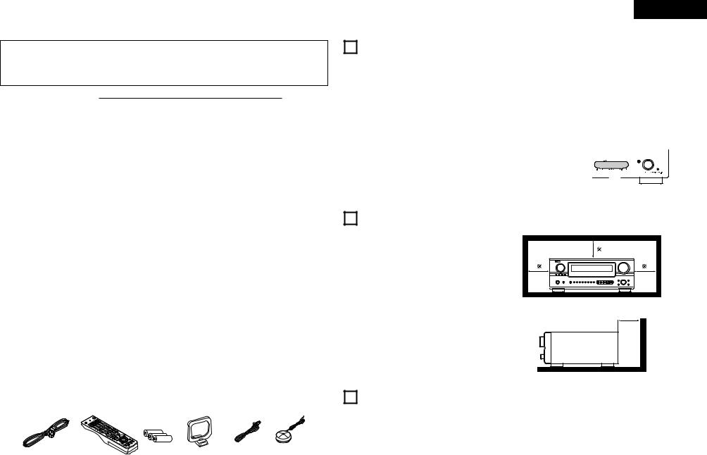
Check that the following parts are included in addition to the main unit:
........................................q Operating instructions |
|
1 |
................................................t R6P/AA batteries |
|
3 |
w Service station list.............................................. |
|
1 |
y AM loop antenna................................................ |
|
1 |
e AC cord .............................................................. |
|
1 |
u FM indoor antenna............................................. |
|
1 |
r Remote control unit (RC-975) |
............................ |
1 |
i Omnidirectional microphone |
..............................1 |
|
e |
r |
t |
y |
u |
i |
|
|
|
|
|
|
ENGLISH
1 BEFORE USING
Pay attention to the following before using this unit:
•Moving the set
To prevent short circuits or damaged wires in the connection cords, always unplug the power cord and disconnect the connection cords between all other audio components when moving the set.
•Before turning the power switch on
Check once again that all connections are proper and that there are not problems with the connection cords. Always set the power switch to the standby position before connecting and disconnecting connection cords.
•Store this instructions in a safe place.
After reading, store this instructions along with the warranty in a safe place.
•Note that the illustrations in this instructions may differ from the actual set for explanation purposes.
•V. AUX terminal
The AVR-2805’s front  panel is equipped with a


 V. AUX terminal. Remove


 the cap covering the

 terminal when you want
to use it.
2 |
CAUTIONS ON INSTALLATION |
|
|
Noise or disturbance of the picture may be generated |
|
||
if this unit or any other electronic equipment using |
10 cm or more |
||
microprocessors is used near a tuner or TV. |
|||
If this happens, take the following steps: |
|
||
• Install this unit as far as possible from the tuner or |
|
||
TV. |
|
|
|
• Set the antenna wires from the tuner or TV away |
|
||
from this unit’s power cord and input/output |
|
||
connection cords. |
|
||
• Noise or disturbance tends to occur particularly |
10 cm or more |
||
when using indoor antennas or 300 Ω/ohms feeder |
|||
|
|||
wires. We recommend using outdoor antennas |
|
||
and 75 Ω/ohms coaxial cables. |
|
||
For heat dispersal, leave at least 10 cm of space |
Wall |
||
|
|||
between the top, back and sides of this unit and |
|
||
the wall or other components. |
|
||
3CAUTIONS ON HANDLING
•Switching the input function when input jacks are not connected
A clicking noise may be produced if the input function is switched when nothing is connected to the input jacks. If this happens, either turn down the MASTER VOLUME control or connect components to the input jacks.
•Muting of PRE OUT jacks, HEADPHONE jack and SPEAKER terminals
The PRE OUT jacks, HEADPHONE jack and SPEAKER terminals include a muting circuit. Because of this, the output signals are greatly reduced for several seconds after the power switch
is turned on or input function, surround mode or any other-set-up is changed. If the volume is turned up during this time, the output will be very high after the muting circuit stops functioning. Always wait until the muting circuit turns off before adjusting the volume.
•Whenever the unit is in the STANDBY state, the apparatus is still connected on AC line voltage. Please be sure to turn the power off (£off) when you leave home for, say, a vacation.
3

ENGLISH
4FEATURES
1.Dolby Digital
Using advanced digital processing algorithms, Dolby Digital provides up to 5.1 channels of widerange, high fidelity surround sound. Dolby Digital is the default digital audio delivery system for DVD and North American DTV.
2.Dolby Pro Logic IIx compatibility
Dolby Pro Logic IIx furthers the matrix decording technology of Dolby Pro Logic II to decode audio signals recorded on two channels into up to 7.1 playback channels, including the surround back channel. Dolby Pro Logic IIx also allows 5.1- channel sources to be played in up to 7.1 channels.
The mode can be selected according to the source. The Music mode is best suited for playing music,the Cinema mode for playing movies, and the Game mode for playing games. The Game mode can only be used with 2-channel audio sources.
3.Dolby Pro Logic II Game mode compatibility
In addition to the previously offered Music and Cinema modes, the AVR-2805 also offers a Game mode optimum for games.
4.DTS (Digital Theater Systems)
DTS provides up to 5.1 channels of wide-range, high fidelity surround sound, from sources such as laser disc, DVD and specially-encoded music discs.
5.DTS-ES Extended Surround and DTS Neo:6
The AVR-2805 can be decoded with DTS-ES Extended Surround, a multi-channel format developed by Digital Theater Systems Inc.
The AVR-2805 can be also decoded with DTS Neo:6, a surround mode allowing 6.1 channels playback of regular stereo sources.
6.DTS 96/24 compatibility
The AVR-2805 can be decoded with sources recorded in DTS 96/24, a multi-channel digital signal format developed by Digital Theater Systems Inc.
DTS 96/24 sources can be played in the multichannel mode on the AVR-2805 with high sound quality of 96 kHz/24 bits or 88.2 kHz/24 bits.
7.Pure Direct Mode/AL24 Processing
The AVR-2805 is equipped with a pure direct mode allowing the effects of the video and digital circuitry to be shut down when playing CDs or records to achieve the ideal environment for analog playback, resulting in extremely high quality music playback. It is also equipped with AL24 processing which compensates the input digital data to produce the near analog waveforms which would be in a nature with 24 bits quality. AL24 processing operates when PCM data such as CD is inputted.
8.Auto Setup/Room EQ
Use of the microphone for setup applications measures the presence of speakers, the distance to the speakers, and other information, and permits automatic setup. The characteristics of each speaker can also be corrected.
9.Multi Zone Music Entertainment System
Multi Source Function:
This unit’s Multi Source function lets you select different audio sources for listening Different sources can thus be enjoyed in the main room (MAIN) and the subroom (ZONE2) simultaneously.
10.Future Sound Format Upgrade Capability via Eight Channel Inputs & Outputs
For future multi-channel audio format(s), the AVR2805 is provided with 7.1 channel (seven main channels, plus one low frequency effects channel) inputs, along with a full set of 7.1 channel pre-amp outputs, controlled by the 8 channel master volume control. This assures future upgrade possibilities for any future multi-channel sound format.
11.Front input Terminal
The unit is equipped with a Front Input connector for the convenient connection of a video camera or other equipment.
12.Video Conversion Function
The AVR-2805 is equipped with a function for upconverting video signals.
Because of this, the AVR-2805’s MONITOR OUT jack can be connected to the monitor (TV) with a set of cables offering a higher quality connection, regardless of how the player and the AVR-2805’s video input jacks are connected.
13.Component Video Switching
In addition to composite video and “S” video switching, the AVR-2805 provides 3 sets of component video (Y, PB/CB, PR/CR) inputs, and one set of component video outputs to the television, for superior picture quality.
14.TRIGGER OUT
AVR-2805 is equipped with 2 systems of 12V TRIGGER OUT connections. Each output can be activated upon the selection of assigned. Main Zone inputs or zone2 inputs.
15.RS-232C Terminal
Includes a RS-232C port to support an AMX, Crestron integrated control system.
16.AC INLET
Detachable AC CORD is used.
17.Auto Surround Mode
This function stores the surround mode last used for an input signal in the memory and automatically sets that surround mode the next time that signal is input.
18.Large-sized fluorescent display
A large-sized fluorescent display is used which also permits a check of the input/output channels.
19.Audio delay
This is a function for delaying the audio signal with respect to the video signal. (0 to 200 msec)
20.Preset Memory Tuning
56-Station AM/FM Random Preset Memory tuning.
4

5 CONNECTIONS
•Do not plug in the AC cord until all connections have been completed.
•Be sure to connect the left and right channels properly (left with left, right with right).
•Insert the plugs securely. Incomplete connections will result in the generation of noise.
•Use the AC OUTLET for audio equipment only. Do not use them for hair driers, etc.
•Note that binding pin plug cords together with AC cords or placing them near a power transformer will result in generating hum or other noise.
•Noise or humming may be generated if a connected audio equipment is used independently without turning the power of this unit on. If this happens, turn on the power of the this unit.
Connecting the audio components
• When making connections, also refer to the operating instructions of the other components.
|
|
Connecting a CD player |
|||
OUTPUT |
CD player |
|
|
||
Connect the CD player’s analog |
|||||
R |
L |
||||
|
|
output |
jacks |
(ANALOG |
|
R |
L |
OUTPUT) to this unit’s CD jacks |
|||
using pin plug cords. |
|
||||
|
|
|
|||
Turntable (MM cartridge)
Connecting a turntable
Connect the turntable’s output cord to the AVR2805’s PHONO jacks, the L (left) plug to the L jack, the R (right) plug to the right jack.
NOTE:
This unit cannot be used with MC cartridges directly. Use a separate head amplifier or step-up transformer.
If humming or other noise is generated when the ground wire is connected, disconnect the ground wire.
Ground wire
R |
RL |
R |
R |
L |
RL |
R |
R |
L |
 Connecting the AC OUTLET AC OUTLET
• SWITCHED
(total capacity – 100 W)
The power to these outlets is turned on and off in conjunction with the POWER operation switch on the main unit, and when the power is switched between on and standby from the remote control unit. No power is supplied from these outlets when this unit’s power is at standby. Never connect equipment whose total capacity is above 100 W.
NOTE:
Only use the AC OUTLET for audio equipment. Never use them for hair driers, TVs or other electrical appliances.
Connecting the pre-out jacks
Use these jacks if you wish to connect external power amplifier(s) to increase the power of the front, center and surround sound channels, or for connection to powered loudspeakers.
To use Surround back with one speaker, connect the speaker to SURR. BACK L CH.
CD player or other component |
Route the connection cords, etc., in |
|
equipped with digital output jacks |
such a way that they do not obstruct |
|
|
the ventilation holes. |
Power supply cord |
OPTICAL COAXIAL |
|
|
OUTPUT |
TRIGGER OUT |
AC 230V, 50Hz |
MD recorder, CD recorder or other component |
|
|
|
Turn the DC 12V voltage on and off for the individual functions. |
|
|
|
For details, see “Setting the Trigger Out Setup”. (See page 26) |
|
equipped with digital input/output jacks |
|
|
|
|
R |
L |
R |
L |
|
|
R |
L |
R L |
NOTE: |
|
INPUT OUTPUT |
If humming noise is generated by a |
|||
|
OPTICAL |
INPUT |
|
OUTPUT |
tape deck, etc., move the tape deck |
|
|
|
|
CD recorder or Tape deck |
|
|
|
|
|
away. |
|
Connecting the DIGITAL jacks |
|
|
|
|
|
Use these for connections to audio equipment with digital output. Refer |
|
Connecting a tape deck |
|
||
|
|
|
|||
to “Setting the Digital in Assignment”. (See page 22) |
|
|
Connections for recording: |
|
|
NOTES: |
|
|
Connect the tape deck’s recording input jacks (LINE IN or REC) to this unit’s |
||
|
|
tape recording (CDR/TAPE OUT) jacks using pin plug cords. |
|||
• |
Use 75 Ω/ohms cable pin cords for coaxial connections. |
|
|
Connections for playback: |
|
• |
Use optical cables for optical connections, removing the cap before |
Connect the tape deck’s playback output jacks (LINE OUT or PB) to this |
|||
|
connecting. |
|
|
||
|
|
|
unit’s tape playback (CDR/TAPE IN) jacks using pin plug cords. |
||
|
|
|
|
||
ENGLISH
Connecting the video components
•To connect the video signal, connect using a 75 Ω/ohms video signal cable cord. Using an improper cable can result in a drop in video quality.
•When making connections, also refer to the operating instructions of the other components.
•The AVR-2805 is equipped with a function for up-converting video signals.
•The signal connected to the video signal terminal is output to the S-Video and component video monitor out terminals.
•The REC OUT terminals have no conversion function, so when recording only connect the video terminals.
|
|
TV or DBS tuner |
|
Connecting a TV or DBS tuner |
|
|
|
|
|
AUDIO VIDEO |
|
|
TV or DBS |
|
|
|
|||
OUT |
|
|||
R L OUT
• Connect the TV’s or DBS tuner’s video output jack (VIDEO OUTPUT) to the
IN jack using a 75 Ω/ohms video coaxial pin plug cord.
R L
•Connect the TV’s or DBS tuner’s audio output jacks (AUDIO OUTPUT) to the using pin plug cords.
AUDIO |
VIDEO |
DVD player or video disc player (VDP), etc. |
OUT |
OUT |
|
R L |
R |
L |
|
Connecting a DVD player or a video disc player (VDP) |
VIDEO (yellow) TV or DBS
AUDIO TV or DBS IN jacks
DVD
• Connect the video disc player’s video output jack (VIDEO OUTPUT) to the VIDEO (yellow) DVD IN jack using a 75 Ω/ohms video coaxial pin plug cord.
•Connect the video disc player’s analog audio output jacks (ANALOG AUDIO OUTPUT) to the AUDIO DVD IN jacks using pin plug cords.
•VDP can be connected to the VDP jacks in the same way.
R |
VIDEO |
|
|
L |
IN |
R |
L |
L |
R |
R |
L |
R |
L |
R |
L |
Monitor TV
MONITOR OUT
•Connect the TV’s video input jack (VIDEO INPUT) to the VIDEO MONITOR OUT jack using a 75 Ω/ohms video
coaxial pin plug cord.
Note on connecting the digital input jacks
• Only audio signals are inputs to the digital input jacks. For details. (See page 5)
Video deck 2
R |
L |
R |
L |
R |
L R |
L OUT IN |
|
OUT |
IN |
|
AUDIO |
VIDEO |
R |
|
R |
Video deck 1 |
L |
L |
R |
L R |
L OUT IN |
|
OUT |
IN |
|
AUDIO |
VIDEO |
Connecting a video decks
• There are two sets of video deck (VCR) jacks, so two video decks can be connected for simultaneous recording or video copying.
Video input/output connections:
• Connect the video deck’s video output jack (VIDEO OUT) to the VIDEO (yellow) VCR-1 IN jack, and the video deck’s video input jack (VIDEO IN) to the
VIDEO (yellow) VCR-1 OUT jack using 75 Ω/ohms video coaxial pin plug cords.
Connecting the audio output jacks
•Connect the video deck’s audio output jacks (AUDIO OUT) to the AUDIO VCR-1 IN jacks, and the video deck’s audio input jacks (AUDIO IN) to the AUDIO VCR-1 OUT jacks using pin plug cords.
Connect the second video deck to the VCR-2 jacks in the same way.
5

ENGLISH
Connecting the video components equipped with S-Video jacks
•When making connections, also refer to the operating instructions of the other components.
•A note on the S input jacks
The input selectors for the S inputs and Video inputs work in conjunction with each other.
•The AVR-2805 is equipped with a function for converting video signals.
•The signal connected to the S-Video signal terminal is output to the composite video and component video monitor out terminals.
•The REC OUT terminals have no conversion function, so when recording only connect the S-Video terminals.
|
Connecting a monitor TV |
DVD player or video disc player (VDP) |
MONITOR OUT |
• Connect the TV’s S video input (S-VIDEO INPUT) to the S-VIDEO |
|
S-VIDEO |
MONITOR OUT jack using a S jack connection cord. |
OUT |
|
Connecting a DVD player or a video disc player (VDP)
DVD
•Connect the DVD player’s S-Video output jack to the S- VIDEO DVD IN jack using a S-Video connection cord.
•VDP can be connected to the VDP jacks in the same way.
•It is also possible to connect a video disc player, DVD player, video camcorder, game machine, etc., to the V.AUX jacks.
S-VIDEO
IN
Monitor TV
TV or satellite broadcast tuner
S-VIDEO
OUT
Connecting a TV or DBS tuner
• Connect the TV’s or DBS tuner’s S video output jack (S-VIDEO OUTPUT) to the S-VIDEO TV or DBS IN jack using an S-Video connection cord.
S-VIDEO |
Video deck 1 |
OUT IN |
|
|
Connecting the video decks
• Connect the video deck’s S output jack (S-OUT) to the S-VIDEO
VCR-1 IN jack and the video deck’s S input jack (S-IN) to the
S-VIDEO VCR-1 OUT jack using S-Video connection cords.
• Connect the video deck’s S output jack (S-OUT) to the S-VIDEO
VCR-2 IN jack and the video deck’s S input jack (S-IN) to the
S-VIDEO VCR-2 OUT jack using S-Video connection cords.
S-VIDEO |
Video deck 2 |
OUT IN |
|
|
Connect the components’ audio inputs and outputs as described. (See page 5)
Connecting the video component equipped with Color Difference (Component - Y, PR/CR, PB/CB) Video jacks
•When making connections, also refer to the operating instructions of the other components.
•The signals input to the color difference (component) video jacks are not outputs to the VIDEO output jack (yellow) or the S-Video output jack.
•Some video sources with component video outputs are labeled Y, CB, CR, or Y, Pb, Pr, or Y, R-Y, B-Y. These terms all refer to component video color difference output.
•The function assigned to the component video input can be changed at the system setup. For details, see “Setting the Video Input Mode”. (See page 23)
COMPONENT |
DVD player |
VIDEO OUT |
|
Y CB CR |
|
COMPONENT
VIDEO IN
Y CB CR
Connecting a DVD player
DVD IN jacks
•Connect the DVD player’s color difference (component) video output jacks (COMPONENT VIDEO OUTPUT) to the COMPONENT VIDEO-1 IN jack using 75 Ω/ohms coaxial video pinplug cords.
•In the same way, another video source with component video outputs such as a TV/DBS tuner, etc., can be connected to the VIDEO-2 color difference (component) video jacks.
Monitor TV
Connecting a monitor TV
MONITOR OUT jack
•Connect the TV’s color difference (component) video input jacks
(COMPONENT VIDEO INPUT) to the COMPONENT MONITOR OUT jack using 75 Ω/ohms coaxial video pin-plug cords.
•The color difference input jacks may be indicated differently on some TVs, monitors or video components (“CR, CB and Y”, “R-Y, B-Y and Y”, “Pr, Pb and Y”, etc.). For details, carefully read the operating instructions included with the TV or other component.
MONITOR OUT jacks
The AVR-2805 is equipped with a function for up-converting video signals. Because of this, the AVR-2805’s MONITOR OUT jack can be connected to the monitor (TV) with a set of cables offering a higher quality connection, regardless of how the player and the AVR-2805’s video input jacks are connected.
Generally speaking, connections using the component video jacks offer the highest quality playback, followed by connections using the S-Video jacks, then connections using the regular video jacks (yellow).
The Video Conversion Function
With the AVR-2805, the Video signal and the S-video signal which were inputted are converted mutually. And also the Video signal and the S-Video signal which were inputted are converted into a higher quality.
This unit’s input jacks The flow of the |
This unit’s output jacks |
this unit’s internal |
|
signals. |
|
(Color Diffrence Video jack) |
(Color Diffrence Video jack) |
(S-Video jack) |
(S-Video jack) |
(Video jack) |
(Video jack) |
NOTE:
Down-converting from the component video signal to the S- Video and composite video signal is not possible, so when not using the component video monitor output terminal connect the player using the S-Video or composite video input terminal.
Cautions on the video conversion function:
When the component video terminals are used to connect the AVR-2805 with a TV (or monitor, projector, etc.) and the video (yellow) or S video terminals are used to connect the AVR-2805 with a VTR, depending on the combination of the TV and VTR the picture may flicker in the horizontal direction, be distorted, be out of sync or not display at all when playing video tapes.
If this happens, connect a commercially available video stabilizer, etc., with a TBC (time base corrector) function between the AVR-2805 and the VTR, or if your VTR has a TBC function, turn it on.
6
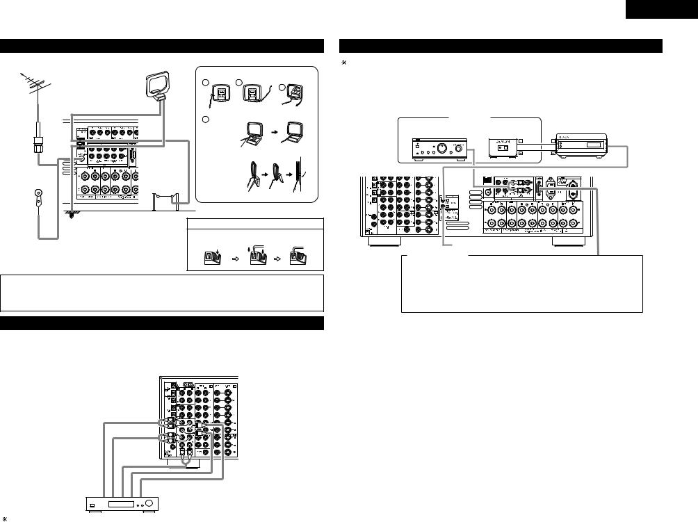
Connecting the antenna terminals
DIRECTION OF |
AM LOOP ANTENNA |
AM loop antenna assembly |
BROADCASTING |
(Supplied) |
Connect to the AM |
STATION |
|
|
|
1 |
antenna terminals. |
|
2 |
|
|
|
3 |
|
FM ANTENNA |
|
|
|
|
75 Ω/ohms |
|
|
Remove the vinyl tie |
Bend in the reverse |
|
|
|
and take out the |
|||
COAXIAL |
|
|
|||
|
4 |
connection line. |
direction. |
||
CABLE |
|
|
|
|
|
|
|
a. With the |
|
|
|
|
|
|
antenna on |
|
|
|
|
|
top any |
|
|
|
|
|
stable |
Mount |
|
|
|
|
surface. |
|
|
|
|
b. With the |
|
|
|
|
|
|
antenna |
|
|
|
AM OUTDOOR |
|
attached to |
|
|
|
|
a wall. |
|
|
|
|
ANTENNA |
|
|
|
|
|
|
|
Installation hole Mount on wall, etc. |
||
FM INDOOR |
|
|
|
|
|
ANTENNA |
GROUND |
|
Connection of AM antennas |
||
(Supplied) |
|
|
|
|
|
1. Push the |
2. Insert the |
3. Return the |
lever. |
conductor. |
lever. |
• An F-type FM antenna cable plug can be connected directly.
Notes:
•Do not connect two FM antennas simultaneously.
•Even if an external AM antenna is used, do not disconnect the AM loop antenna.
•Make sure AM loop antenna lead terminals do not touch metal parts of the panel.
Connecting the external input (EXT. IN) jacks
•These jacks are for inputting multi-channel audio signals from an outboard decoder, or a component with a different type of multi-channel decoder, such as a DVD Audio player, a multi-channel SACD player, or other future multi-channel sound format decoder.
•When making connections, also refer to the operating instructions of the other components.
ENGLISH
Connecting the MULTI ZONE jacks
For instructions on operations using the MULTI ZONE FUNCTIONS. (See pages 38, 39)
[1] ZONE2 preout CONNECTIONS
•If another power amplifier or pre-main (integrated) amplifier or is connected, the ZONE2 preout (variable/fixed level) jacks can be used to play a different program source in ZONE2 the same time. (See page 38)
•The ZONE2 video out is only for the ZONE2.
|
ZONE2 |
|
|
|
|
|
|
INFRARED |
|
Integrated pre-main amplifier |
INFRARED |
|||
RETRANSMITTER |
||||
or power amplifier |
SENSOR |
OUTPUT INPUT |
||
+ |
+ |
AUX OUT |
L |
|
|
R |
|
|
Extension jacks for future use.
CONTROL terminal
Perform the following operation before using an external controller connected to the RS-232C terminal:
1.Press the ON/STANDBY button on the main unit and set the unit to the operating mode.
2.Perform the operation to turn off the power from the external control.
3.Check that the product has been set to the standby mode.
After checking the above, check the connections of the external controller. Operation is possible.
R |
L |
R |
L |
R |
L |
Front |
Surround |
Surround back |
Subwoofer |
Center |
Decoder with 8- or 6-channel analog output
For instructions on playback using the external input (EXT. IN) jacks. (See page 35)
7

ENGLISH
[2] ZONE2 SPEAKER OUT and PREOUT CONNECTIONS
•If another power amplifier or pre-main (integrated) amplifier is connected, the ZONE2 output terminals can be used to play a different program source in ZONE2 the same time.
•ZONE2 SPEAKER OUT can be used when “ZONE2” is selected at System Setup Menu “Power Amp Assign”. In this case, Surround Back Speaker OUT cannot be used for MAIN ZONE. (See page 25)
ZONE2
Integrated pre-main amplifier or power amplifier
INFRARED |
|
|
INFRARED |
|
|
RETRANSMITTER |
|
SENSOR |
OUTPUT |
INPUT |
|
|
+ |
+ |
AUX OUT |
L |
|
|
|
R |
|
|
|
Extension jacks for future use.
NOTE:
• The settings must be changed  to use this speaker for ZONE2. (See page 25.)
(L) (R)
SURROUND BACK/ZONE2 SPEAKER SYSTEMS
Connecting the video component equipped with V. AUX jacks
To connect the video signal, connect using a 75 Ω/ohms video signal cable cord.
|
|
|
|
|
Video game |
|
|
|
|
|
|
OUTPUT |
|
Connecting a Video game component |
|
|
|
|
|
|
• Connect the Video game component’s output |
||
|
|
R |
L |
OPTICAL VIDEO OUT S-VIDEO OUT |
|||
|
|
|
|
|
|
|
jacks to this unit’s V. AUX INPUT jacks. |
|
|
R |
L |
|
|
|
|
|
|
LINE OUT |
|
DIGITAL OUT |
VIDEO OUT |
S-VIDEO OUT |
|
L |
R |
|
|
|
|
|
|
|
|
|
Video camera |
|
Connecting a video camera component |
||
|
|
|
|
|
|
|
|
|
|
|
OUTPUT |
|
• Connect the video camera component’s |
||
|
R |
L |
VIDEO OUT |
S-VIDEO OUT |
|
||
|
|
|
|
|
|
|
output jacks to this unit’s V. AUX INPUT |
|
R |
L |
|
|
|
|
jacks. |
|
LINE OUT |
|
|
|
|
|
The V. AUX terminal is covered with a cap. |
|
VIDEO OUT |
|
|
|
Remove this cap in order to use the |
||
|
|
|
|
terminal. (See page 3 for instructions on |
|||
|
|
S-VIDEO OUT |
|
||||
|
|
|
removing the cap.) |
||||
Speaker system connections
• |
Connect the speaker terminals with the speakers |
Speaker Impedance |
|||
|
making sure that like polarities are matched (≈ with |
• |
Speakers |
with an impedance of from 6 to 16 |
|
|
≈, √ with √ ). Mismatching of polarities will result |
|
Ω/ohms can be connected for use as front, center, |
||
|
in weak central sound, unclear orientation of the |
|
surround and surround back speakers. |
||
|
various instruments, and the sense of direction of |
• Be careful when using two pairs of front speakers |
|||
|
the stereo being impaired. |
|
|
(A + B) at the same time, since use of speakers |
|
• |
When making connections, take care that none of |
|
with an impedance of less than 8 Ω/ohms will lead |
||
|
the individual conductors of the speaker cord come |
|
to damage. |
||
|
in contact with adjacent terminals, with other |
• |
The protector circuit may be activated if the set is |
||
|
speaker cord conductors, or with the rear panel. |
|
played for long periods of time at high volumes |
||
|
|
|
|
when speakers with an impedance lower than the |
|
|
|
|
|
specified impedance are connected. |
|
NOTE: |
|
|
|||
|
|
|
|
||
NEVER touch the speaker terminals when the |
|
|
|
||
power is on. |
|
|
|
|
|
Doing so could result in electric shocks. |
|
|
|
|
|
|
|
|
|||
|
|
||||
|
Connecting the speaker terminals |
||||
|
|
|
|
||
|
1. Loosen by turning |
2. Insert the cord. |
3. Tighten by turning |
||
|
counterclockwise. |
|
|
|
clockwise. |
Either tightly twist or terminate the core wires.
Protector circuit
•This unit is equipped with a high-speed protection circuit. The purpose of this circuit is to protect the speakers under circumstances such as when the output of the power amplifier is inadvertently shortcircuited and a large current flows, when the temperature surrounding the unit becomes unusually high, or when the unit is used at high output over a long period which results in an extreme temperature rise.
When the protection circuit is activated, the speaker output is cut off and the power supply indicator LED flashes. Should this occur, please follow these steps: be sure to switch off the power of this unit, check whether there are any faults with the wiring of the speaker cables or input cables, and wait for the unit to cool down if it is very hot. Improve the ventilation condition around the unit and switch the power back on. If the protection circuit is activated again even though there are no problems with the wiring or the ventilation around the unit, switch off the power and contact a DENON service center.
Note on speaker impedance
•The protector circuit may be activated if the set is played for long periods of time at high volumes when
speakers with an impedance lower than the specified impedance (for example speakers with an impedance of lower than 4 Ω/ohms) are connected. If the protector circuit is activated, the speaker output is cut off. Turn off the set’s power, wait for the set to cool down, improve the ventilation around the set, then turn the power back on.
8

Connections
• When making connections, also refer to the operating instructions of the other components.
|
|
|
|
|
|
|
|
|
Connection |
jack for |
|
|
|
|
|
|
|
|
|
|
|
|
|
|
|
SURROUND SPEAKER |
subwoofer with built-in |
CENTER SPEAKER |
|
|
|
FRONT SPEAKER |
|
||||||||||||||||||
|
|
SYSTEMS |
SYSTEM |
|
|
|
SYSTEMS (A) |
|
|||||||||||||||||
|
|
amplifier (super woofer), |
|
|
|
|
|||||||||||||||||||
|
|
|
|
|
|
|
|
|
etc. |
|
|
|
|
|
|
|
|
|
|
|
|
|
|
|
|
|
|
|
|
|
|
|
|
|
|
|
|
|
|
|
|
|
|
|
|
|
|
|
|
|
|
|
|
|
|
|
|
|
|
|
|
|
|
|
|
|
|
|
|
|
|
|
|
|
|
|
|
(L) |
(R) |
(L) |
(R) |
|
|
NOTES: |
•Precautions when connecting speakers
If a speaker is placed near a TV or video monitor, the colors on the screen may be disturbed by the speaker’s magnetism. If this should happen, move the speaker away to a position where it does not have this effect.
• To use Surround back with one speaker, connect the speaker to SURR. BACK L CH.
•The settings must be changed to use this speaker for ZONE2.
See page 25.
(L) (R)
(L) (R)
SURROUND BACK/MULTI ZONE SPEAKER SYSTEMS |
|
FRONT SPEAKER SYSTEMS (B) |
|
|
|
ENGLISH
6 PART NAMES AND FUNCTIONS
Front Panel
• For details on the functions of these parts, refer to the pages given in parentheses ( ).
@4 @3 |
@2 |
@1 |
@0 |
@7 |
|
|
|
|
|
@8 |
@6@5 |
|
|
|
|
|
w |
|
|
|
|
|
|
y i !0 !2 |
|
!5 |
!9 |
q e |
r t u o !1 |
!3 |
!4 !6!7!8 |
||
q Power ON/STANDBY switch |
..........................(34) |
w POWER indicator............................................ |
(34) |
e Power switch ........................................... |
(34, 52) |
r Headphone jack (PHONES) ............................ |
(36) |
t INPUT MODE button ..................................... |
(34) |
y ANALOG button ............................................. |
(34) |
u EXT. IN button .......................................... |
(34, 35) |
i PURE DIRECT button ..................................... |
(36) |
o FRONT SPEAKER button ............................... |
(34) |
!0SURROUND BACK button ............................. |
(42) |
!1DIMMER button ............................................. |
(37) |
!2STATUS button ............................................... |
(37) |
!3V. AUX input jacks ............................................ |
(8) |
!4SETUP MIC jack ............................................. |
(13) |
!5SURROUND MODE button...................... |
(35, 46) |
!6SURROUND PARAMETER button ........... |
(40~42) |
|
!7SELECT knob................... |
(35, 36, 40~44, 46, 47) |
|
!8TONE DEFEAT button .................................... |
|
(36) |
!9TONE CONTROL button .......................... |
|
(36, 47) |
@0MASTER VOLUME control ............................ |
(35) |
|
@1MASTER VOLUME indicator |
|
|
(VOLUME LEVEL)........................................... |
|
(35) |
@2Display |
|
|
@3Remote control sensor |
|
|
(REMOTE SENSOR) ....................................... |
|
(29) |
@4FUNCTION knob .................... |
(34, 37, 38, 48, 49) |
|
@5VIDEO SELECT button ................................... |
|
(37) |
@6ZONE2/REC SELECT button .................... |
(37, 38) |
|
@7TUNING PRESET button ................................ |
|
(49) |
@8SOURCE button ............................................. |
|
(34) |
9

ENGLISH |
|
|
|
|
|
Display |
|
|
|
|
|
!5!4!3!2 |
!1 |
!0 |
oi |
u |
y |
q w |
|
e |
|
|
r t |
qINPUT SIGNAL indicator
The respective indicator will light corresponding to the input signal.
wINPUT SIGNAL CHANNEL indicator
The channels included in the input source will light.
This displays bitstream signal channel.
This does not light when signals are being input to the ANALOG or EXT.IN connectors.
eInformation display
This displays the surround mode, function name or setting value, etc.
rOUTPUT SIGNAL CHANNEL indicator
The audio channels output from this unit will light.
tSPEAKER indicator
This lights corresponding to the settings of the front speakers.
yDecoder indicator
This lights when each decoder is operating.
uMASTER VOLUME indicator This displays the volume level.
The Setup item number is displayed in System Setup.
iMULTI (ZONE) indicator
ZONE2 mode is selected in ZONE2/REC SELECT.
oREC OUT SOURCE indicator
REC OUT mode is selected in ZONE2/REC SELECT.
!0AL24 indicator
The AL24 indicator lights when the PURE DIRECT, DIRECT and STEREO mode is selected in the PCM input signal.
!1INPUT MODE indicator
This lights corresponding to the setting of the INPUT mode.
!2AUTO indicator
This lights when the broadcast station is selected in the AUTO tuning mode.
!3RDS indicator
This lights when an RDS broadcast has been received.
!4TUNED indicator
This lights when an FM/AM broadcast has been received.
!5STEREO indicator
This lights when an FM stereo broadcast has been received.
Remote control unit
• For details on the functions of these parts, refer to the pages given in parentheses ( ).
|
|
Remote control signal |
|
|
|
transmitter ................................... |
(29) |
LED (indicator) ....................... |
(30~33) |
|
|
|
|
Power buttons ....................... |
(30~34) |
ZONE 2 buttons ........................... |
(39) |
ZONE 1/MAIN buttons................. |
(39) |
Mode selector |
|
|
|
buttons ............................ |
(11, 29~34) |
|
|
|
|
Tuner system/System |
|
|
|
buttons ............................ |
(29, 48~51) |
Input source selector |
|
|
|
buttons............................. |
(30, 31, 34) |
|
|
|
|
Surround buttons |
|
|
|
......................(35, 36, 40~42, 44, 45) |
|
MODE SELECT button |
................(29) |
|
|
|
|
Master volume control |
|
System buttons ..................... |
(29~32) |
buttons................................... |
(35, 39) |
|
|
MUTING button ........................... |
(36) |
SYSTEM SETUP/SETUP |
|
|
|
|
|
|
|
|
|
|
|
button |
(11, 13, 28) |
|
|
|
|
|
|
|
|||
|
|
|
|
|
|
|
|
|
|
|
|
Cursor buttons ............................. |
(11) |
|
|
|
|
|
|
|
|
||
|
|
|
|
|
|
..ON SCREEN/DISPLAY button |
(37, 43) |
|
|
|
|
|
|
|
|
|
|
|
|
|
|
......................TEST TONE button |
(39) |
|
|
|
|
||
|
|
|
|
|
|
|
|
................SYSTEM CALL buttons |
(32) |
|
|
|
|
|
|
|
|
|
|
USE/LEARN button |
(31, 33) |
|
|
|
|
||
|
|
|
|
SURROUND PARAMETER |
|
|
button ........................ |
(40~42, 45, 46) |
|
CH SELECT/ENTER button |
|
|
......................................... |
(11, 39. 40) |
|
RDS/RETURN button............. |
|
(50~52) |
FRONT SPEAKER button............. |
(34) |
|
SURROUND BACK button........... |
(42) |
|
INPUT MODE selector |
|
|
buttons................................... |
|
(34, 35) |
10
7SETTING UP THE SYSTEM
•Once all connections with other AV components have been completed as described in “CONNECTIONS” (see pages 5 to 9), make the various settings described below on the monitor screen using the AVR-2805’s on-screen display function.
These settings are required to set up the listening room’s AV system centered around the AVR-2805.
Use the following buttons to set up the system
• Use the following buttons to set up the system.
1 Check that the remote control unit set to AMP mode. (TAPE, CDR/MD, CD)
(Remote control unit)
2 |
SYSTEM SETUP button |
|
|
|
Press this to display the system setup menu. |
|
CURSOR buttons |
|
Use these to move the cursors the left, right, up and |
|
down on the screen. |
|
ENTER button |
|
Press this to switch the display. |
|
Also use this button to complete the setting. |
• System setup items and default values (set upon shipment from the factory)
1. Auto Setup/Room EQ
|
|
Auto Setup/Room EQ |
Default settings |
||
|
|
|
|
|
|
1 |
|
Power Amp |
Set this to switch the surround |
|
|
Auto Setup |
back channel’s power amplifier |
SURROUND BACK |
|||
Assignment |
|||||
|
|
for use for zone2. |
|
||
|
|
|
|
||
|
|
|
|
|
|
2 |
Manual EQ |
This parameter is for optimizing the Room EQ with |
|
||
which the audio signals are produced from the |
All Channel and Frequency=0 dB |
||||
Setup |
|||||
speakers. |
|
|
|||
|
|
|
|
||
|
|
|
|
|
|
3 |
Room EQ |
Set the Room EQ setting with All or Assign for |
All |
||
Setup |
each surround mode. |
||||
|
|||||
|
|
|
|
|
|
4 |
Direct Mode |
Set the ON/OFF setting of Room EQ, in the case of |
OFF |
||
Setup |
the surround mode is in Direct or Pure Direct. |
||||
|
|||||
|
|
|
|
|
|
5 |
Mic Input |
Set this to switch the Mic Input jack for use for Mic |
Mic |
||
Select |
or V.Aux L-channel input jack. |
||||
|
|||||
|
|
|
|
|
|
ENGLISH
2. Speaker Setup
|
|
Speaker Setup |
|
|
|
|
|
|
|
|
|
|
Default settings |
|
|
|
|
|
|
|
|
|
|
|
|
|
|||||||
|
|
|
|
|
|
|
|
|
|
|
|
|
|
|
|
|
|
|
|
|
|
|
|
|
|
|
|
|
|
|
|||
|
|
Input the combination of speakers |
|
in your |
Front Sp. |
|
Center Sp. |
|
Subwoofer |
Surround Sp. |
|
Surround Back |
|||||||||||||||||||||
|
|
system and their corresponding sizes (SMALL for |
|
|
|
||||||||||||||||||||||||||||
|
|
|
|
|
|
|
|
|
|
Sp. |
|||||||||||||||||||||||
|
Speaker |
regular speakers, LARGE for full-size, full-range) to |
|
|
|
|
|
|
|
|
|
|
|
|
|
|
|
|
|
|
|
|
|
|
|
||||||||
1 |
|
|
|
|
|
|
|
|
|
|
|
|
|
|
|
|
|
|
|
|
|
|
|
|
|
|
|||||||
Configuration |
automatically set the composition of the signals |
|
|
|
|
|
|
|
|
|
|
|
|
|
|
|
|
|
|
|
|
|
|
|
|
|
|
||||||
|
|
|
|
|
|
|
|
|
|
|
|
|
|
|
|
|
|
|
|
|
|
|
|
|
|
|
|||||||
|
|
output from |
the |
speakers |
and the frequency |
Large |
|
Small |
|
|
|
Yes |
|
Small |
|
|
|
|
Small / 2spkrs |
||||||||||||||
|
|
response. |
|
|
|
|
|
|
|
|
|
|
|
|
|
|
|||||||||||||||||
|
|
|
|
|
|
|
|
|
|
|
|
|
|
|
|
|
|
|
|
|
|
|
|
|
|
|
|
|
|
|
|
|
|
|
|
|
|
|
|
|
|
|
|
|
|
|
|
|
|
|
|
|
|
|
|
|
|
|
|
|
|||||||
|
|
This parameter is for optimizing the timing with |
Front L & R |
|
Center |
|
|
Subwoofer |
|
Surround L & R |
|
|
SBL & SBR |
||||||||||||||||||||
2 |
Delay Time |
which the audio |
signals are produced |
from the |
|
|
|
|
|
|
|
|
|
|
|
|
|
|
|
|
|
|
|
|
|
|
|
|
|
|
|||
speakers and subwoofer according to the listening |
3.6 m (12 ft) |
3.6 m (12 ft) |
|
3.6 m (12 ft) |
|
3.0 m (10 ft) |
|
|
3.0 m (10 ft) |
||||||||||||||||||||||||
|
|
|
|
|
|
||||||||||||||||||||||||||||
|
|
position. |
|
|
|
|
|
|
|
|
|
||||||||||||||||||||||
|
|
|
|
|
|
|
|
|
|
|
|
|
|
|
|
|
|
|
|
|
|
|
|
|
|
||||||||
|
Channel |
This adjusts the volume of the signals output from |
Front L |
Front R |
Center |
Surround |
Surround |
Surround |
Surround |
|
Subwoofer |
||||||||||||||||||||||
3 |
the speakers and subwoofer for the |
|
different |
|
|
|
|
|
|
|
L |
R |
|
Back L |
|
Back R |
|
|
|
|
|
||||||||||||
Level |
|
|
|
|
|
|
|
|
|
|
|
|
|
|
|
|
|
|
|
|
|
|
|
|
|
|
|
||||||
|
channels in order to obtain optimum effects. |
0 dB |
0 dB |
|
0 dB |
|
0 dB |
0 dB |
|
0 dB |
|
0 dB |
|
|
|
|
0 dB |
||||||||||||||||
|
|
|
|
|
|
|
|
|
|
||||||||||||||||||||||||
|
|
|
|
|
|
|
|
|
|
|
|
|
|
|
|
||||||||||||||||||
|
|
|
|
|
|
|
|
|
|
|
|
|
|
|
|
|
|
|
|
|
|
|
|
|
|
|
|
|
|
||||
4 |
Crossover |
Set the frequency (Hz) below which the bass so of |
|
|
|
|
|
|
|
|
|
|
|
|
|
|
|
|
|
|
|
|
|
|
|
|
|
|
|||||
the various |
speaker is to |
be output |
from the |
|
|
|
|
|
|
|
|
|
80Hz |
|
|
|
|
|
|
|
|
|
|
|
|
|
|
|
|||||
Frequency |
|
|
|
|
|
|
|
|
|
|
|
|
|
|
|
|
|
|
|
|
|
|
|
|
|||||||||
|
subwoofer. |
|
|
|
|
|
|
|
|
|
|
|
|
|
|
|
|
|
|
|
|
|
|
|
|
|
|
|
|
|
|
|
|
|
|
|
|
|
|
|
|
|
|
|
|
|
|
|
|
|
|
|
|
|
|
|
|
|
|
|
|
|
|
|
|
|
|
|
|
|
|
|
|
|
|
|
|
|
|
|
|
|
|
|
|
|
|
|
|
|
|
|
|
|
|
|
|
|
|
|
|
5 |
Subwoofer |
This selects |
the |
subwoofer |
speaker for playing |
|
|
|
|
|
|
|
|
|
LFE |
|
|
|
|
|
|
|
|
|
|
|
|
|
|
|
|||
Mode |
deep bass signals. |
|
|
|
|
|
|
|
|
|
|
|
|
|
|
|
|
|
|
|
|
|
|
|
|
|
|
|
|||||
|
|
|
|
|
|
|
|
|
|
|
|
|
|
|
|
|
|
|
|
|
|
|
|
|
|
|
|
|
|
||||
|
|
|
|
|
|
|
|
|
|
|
|
|
|
|
|
|
|
|
|
|
|
|
|
|
|
|
|
|
|
|
|
|
|
3. Input Setup |
|
|
|
|
|
|
|
|
|
|
|
|
|
|
|
|
|
|
|
|
|
|
|
|
|
|
|
|
|
|
|
||
|
|
|
|
|
|
|
|
|
|
|
|
|
|
|
|
|
|
|
|
|
|
|
|
|
|
|
|
|
|||||
|
|
Input Setup |
|
|
|
|
|
|
|
|
|
|
Default settings |
|
|
|
|
|
|
|
|
|
|
|
|
|
|||||||
|
|
|
|
|
|
|
|
|
|
|
|
|
|
|
|
|
|
|
|
|
|
|
|
|
|
|
|
|
|
|
|
|
|
|
|
|
|
|
|
|
Input |
CD |
DVD |
|
VDP |
|
TV |
|
DBS |
|
V. AUX |
|
VCR-1 |
|
VCR-2 |
|
|
CDR/ |
|||||||||
|
Digital In |
This assigns the digital input jacks for the |
|
source |
|
|
|
|
|
|
|
|
TAPE |
||||||||||||||||||||
1 |
|
|
|
|
|
|
|
|
|
|
|
|
|
|
|
|
|
|
|
|
|
|
|
|
|
|
|||||||
|
|
|
|
|
|
|
|
|
|
|
|
|
|
|
|
|
|
|
|
|
|
|
|
|
|
|
|
||||||
Assignment |
different input sources. |
|
|
Digital |
COAX1 |
COAX2 |
OPT1 |
OFF |
|
OPT2 |
|
OPT5 |
|
OPT3 |
|
OFF |
|
|
|
OPT4 |
|||||||||||||
|
|
|
|
|
|
|
|
|
|
||||||||||||||||||||||||
|
|
|
|
|
|
|
|
|
|
|
|
|
|
||||||||||||||||||||
|
|
|
|
|
|
|
Inputs |
|
|
|
|
|
|
|
|||||||||||||||||||
|
|
|
|
|
|
|
|
|
|
|
|
|
|
|
|
|
|
|
|
|
|
|
|
|
|
|
|
|
|
|
|
|
|
|
|
|
|
|
|
|
|
|
|
|
|
|
|
|
|
|
|
|
|
|
|
|
|
|
|
|
|
|
|
|
|
|
|
2 |
Ext. In |
Set the Ext. In |
Subwoofer terminal |
playback |
|
|
|
|
|
|
|
|
|
|
|
|
|
|
|
|
|
|
|
|
|
|
|
|
|
|
|||
Subwoofer |
|
|
|
|
|
|
Subwoofer = +15 dB |
|
|
|
|
|
|
|
|
|
|
|
|
|
|||||||||||||
level. |
|
|
|
|
|
|
|
|
|
|
|
|
|
|
|
|
|
|
|
|
|
|
|
|
|||||||||
|
Level |
|
|
|
|
|
|
|
|
|
|
|
|
|
|
|
|
|
|
|
|
|
|
|
|
|
|
|
|
|
|
|
|
|
|
|
|
|
|
|
|
|
|
|
|
|
|
|
|
|
|
|
|
|
|
|
|
|
|
|
|
|
|
|
|
|
|
|
|
|
|
|
|
|
|
|
|
|
|
|
|
|
|
|
|
|
|
|
|
|
|
|
|
|
|
||||||
|
Component |
This assigns |
the |
color difference (component) |
DVD |
VDP |
|
TV |
DBS |
|
VCR-1 |
VCR-2 |
|
|
V. AUX |
|
|
— |
|
|
|
— |
|||||||||||
3 |
|
|
|
|
|
|
|
|
|
|
|
|
|
|
|
|
|
|
|
|
|
|
|
|
|
|
|||||||
|
|
|
|
|
|
|
|
|
|
|
|
|
|
|
|
|
|
|
|
|
|
|
|
|
|
||||||||
In Assign |
video input jacks for the different input sources. |
VIDEO |
NONE |
|
VIDEO |
VIDEO |
|
NONE |
NONE |
|
|
NONE |
|
|
— |
|
|
|
— |
||||||||||||||
|
|
|
|
|
|
|
|
|
|
||||||||||||||||||||||||
|
|
|
|
|
|
|
|
1 |
|
2 |
|
3 |
|
|
|
|
|
|
|
|
|||||||||||||
|
|
|
|
|
|
|
|
|
|
|
|
|
|
|
|
|
|
|
|
|
|
|
|
|
|
|
|
|
|
||||
|
|
|
|
|
|
|
|
|
|
|
|
|
|
|
|
|
|
|
|
|
|
|
|
|
|
|
|
|
|
||||
4 |
Video Input |
Set the input signal to be output from the monitor |
|
|
|
|
|
|
|
|
|
AUTO |
|
|
|
|
|
|
|
|
|
|
|
|
|
|
|
||||||
Mode |
output terminal. |
|
|
|
|
|
|
|
|
|
|
|
|
|
|
|
|
|
|
|
|
|
|
|
|
|
|
|
|
||||
|
|
|
|
|
|
|
|
|
|
|
|
|
|
|
|
|
|
|
|
|
|
|
|
|
|
|
|
|
|
|
|||
|
|
|
|
|
|
|
|
|
|
|
|
|
|
|
|
|
|
|
|
|
|
|
|||||||||||
|
|
|
|
|
|
|
|
A1 ~ A8 |
|
87.5/89.1/98.1/108.0/90.1/90.1/90.1/90.1 MHz |
|
|
|
|
|
|
|
|
|||||||||||||||
|
|
|
|
|
|
|
|
|
|
|
|
|
|
|
|||||||||||||||||||
|
|
|
|
|
|
|
|
B1 ~ B8 |
|
522/603/999/1404/1611 kHz, 90.1/90.1/90.1 MHz |
|
|
|
|
|||||||||||||||||||
|
|
|
|
|
|
|
|
|
|
|
|
|
|
|
|
|
|
|
|
|
|
|
|
|
|
|
|
|
|
|
|
||
|
|
|
|
|
|
|
|
C1 ~ C8 |
|
90.1 MHz |
|
|
|
|
|
|
|
|
|
|
|
|
|
|
|
|
|
|
|
|
|
||
5 |
Auto Tuner |
FM stations are received automatically and stored |
|
|
|
|
|
|
|
|
|
|
|
|
|
|
|
|
|
|
|
|
|
|
|
|
|
|
|||||
D1 ~ D8 |
|
90.1 MHz |
|
|
|
|
|
|
|
|
|
|
|
|
|
|
|
|
|
|
|
|
|
||||||||||
Presets |
in the memory. |
|
|
|
|
|
|
|
|
|
|
|
|
|
|
|
|
|
|
|
|
|
|
|
|
|
|
||||||
|
|
|
|
|
|
|
|
|
|
|
|
|
|
|
|
|
|
|
|
|
|
|
|
|
|
|
|
|
|
|
|||
|
|
|
|
|
|
|
|
E1 ~ E8 |
|
90.1 MHz |
|
|
|
|
|
|
|
|
|
|
|
|
|
|
|
|
|
|
|
|
|
||
|
|
|
|
|
|
|
|
|
|
|
|
|
|
|
|
|
|
|
|
|
|
|
|
|
|
|
|
|
|
|
|
||
|
|
|
|
|
|
|
|
F1 ~ F8 |
|
90.1 MHz |
|
|
|
|
|
|
|
|
|
|
|
|
|
|
|
|
|
|
|
|
|
||
|
|
|
|
|
|
|
|
|
|
|
|
|
|
|
|
|
|
|
|
|
|
|
|
|
|
|
|
|
|
|
|
||
|
|
|
|
|
|
|
|
G1 ~ G8 |
|
90.1 MHz |
|
|
|
|
|
|
|
|
|
|
|
|
|
|
|
|
|
|
|
|
|
||
|
|
|
|
|
|
|
|
|
|
|
|
|
|
|
|
|
|
|
|
|
|
|
|
|
|
|
|
|
|
|
|
|
|
11

ENGLISH
4. Advanced Playback
|
|
Advanced Playback |
|
|
|
|
|
Default settings |
|
|
|
|
||||
|
|
|
|
|
|
|
|
|
|
|
|
|
|
|
|
|
1 |
Audio Delay |
Set the audio delay to delay time the sound and |
|
|
|
|
|
|
0 ms |
|
|
|
|
|
|
|
synchronize it with the picture. |
|
|
|
|
|
|
|
|
|
|
|
|
||||
|
|
|
|
|
|
|
|
|
|
|
|
|
|
|
|
|
|
|
|
|
|
|
|
|
|
|
|
|
|
|
|
|
|
2 |
Dolby Digital |
Turn the audio compression on or off when down- |
|
|
|
|
|
|
OFF |
|
|
|
|
|
|
|
Setup |
mixing Dolby Digital signals. |
|
|
|
|
|
|
|
|
|
|
|
|
|||
|
|
|
|
|
|
|
|
|
|
|
|
|
|
|
||
|
|
|
|
|
|
|
|
|
|
|
|
|
|
|
|
|
3 |
Auto |
|
|
|
|
|
|
|
|
|
|
|
|
|
|
|
Surround |
Set the Auto surround mode function. |
|
|
|
|
Auto Surround Mode = ON |
|
|
|
|||||||
|
Mode |
|
|
|
|
|
|
|
|
|
|
|
|
|
|
|
|
|
|
|
|
|
|
|
|
|
|
|
|
|
|
|
|
5. Option Setup |
|
|
|
|
|
|
|
|
|
|
|
|
|
|
||
|
|
|
|
|
|
|
|
|
|
|
|
|
|
|
|
|
|
|
Option Setup |
|
|
|
|
|
Default settings |
|
|
|
|
||||
|
|
|
|
|
|
|
|
|
|
|
|
|
|
|
|
|
1 |
Power AMP |
Set this to switch the surround back channel’s |
|
|
|
|
|
Surround Back |
|
|
|
|
||||
Assignment |
power amplifier for use for zone2. |
|
|
|
|
|
|
|
|
|
||||||
|
|
|
|
|
|
|
|
|
|
|
|
|
|
|
||
|
|
|
|
|
|
|
|
|
|
|
|
|
|
|
|
|
2 |
Zone2 vol. |
This sets the output level the zone2 output jacks. |
|
|
|
|
|
|
|
|
|
|
|
|
|
|
This menu is not displayed, when “ZONE2” is |
|
|
|
|
|
|
Variable |
|
|
|
|
|
|
|||
Level |
|
|
|
|
|
|
|
|
|
|
|
|
||||
|
selected at Option Setup “Power Amp Assign”. |
|
|
|
|
|
|
|
|
|
|
|
|
|
|
|
|
|
|
|
|
|
|
|
|
|
|
|
|
|
|
|
|
|
|
|
|
|
|
|
|
|
|
|
|
|
|
|
|
|
|
|
|
|
|
|
|
|
ZONE=MAIN |
|
|
|
|
||||
|
|
|
|
|
|
|
|
|
|
|
|
|
|
|
|
|
3 |
Trigger Out1 |
Set the Trigger Out1 output for the each input |
PHONO |
CD |
TUNER |
|
CDR/ |
DVD |
VDP |
|
TV |
|
DBS |
VCR-1 |
VCR-2 |
V. AUX |
Setup |
sources. |
|
TAPE |
|
|
|||||||||||
|
|
|
|
|
|
|
|
|
|
|
|
|
|
|
||
|
|
|
|
|
|
|
|
|
|
|
|
|
|
|
|
|
|
|
|
OFF |
OFF |
OFF |
|
OFF |
ON |
ON |
|
ON |
|
ON |
ON |
ON |
ON |
|
|
|
|
|
|
|
|
|
|
|
|
|
|
|
|
|
|
|
|
|
|
|
|
|
|
ZONE=2 |
|
|
|
|
|||
|
|
|
|
|
|
|
|
|
|
|
|
|
|
|
|
|
4 |
Trigger Out2 |
Set the Trigger Out2 output for the each input |
PHONO |
CD |
TUNER |
|
CDR/ |
DVD |
VDP |
|
TV |
|
DBS |
VCR-1 |
VCR-2 |
V. AUX |
Setup |
sources. |
|
TAPE |
|
|
|||||||||||
|
|
|
|
|
|
|
|
|
|
|
|
|
|
|
||
|
|
|
|
|
|
|
|
|
|
|
|
|
|
|
|
|
|
|
|
ON |
ON |
ON |
|
ON |
ON |
ON |
|
ON |
|
ON |
ON |
ON |
ON |
|
|
|
|
|
|
|
|
|
|
|
|
|
|
|
|
|
5 |
Muting Level |
This sets the amount of attenuation at audio |
|
|
|
|
|
---dB (minimum) |
|
|
|
|
||||
output muting. |
|
|
|
|
|
|
|
|
|
|||||||
|
|
|
|
|
|
|
|
|
|
|
|
|
|
|
|
|
|
|
|
|
|
|
|
|
|
|
|
|
|
|
|
|
|
|
|
This sets whether or not to display the on-screen |
|
|
|
|
|
|
|
|
|
|
|
|
|
|
6 |
On Screen |
display that appears on the monitor screen when |
|
|
|
|
|
|
|
|
|
|
|
|
|
|
the controls on the remote control unit or main unit |
|
|
|
On Screen Display = ON / Mode 1 |
|
|
||||||||||
Display |
|
|
|
|
|
|||||||||||
|
are operated. |
|
|
|
|
|
|
|
|
|
|
|
|
|
|
|
|
|
|
|
|
|
|
|
|
|
|
|
|
|
|
|
|
|
|
A setting to prevent flickering. |
|
|
|
|
|
|
|
|
|
|
|
|
|
|
|
|
|
|
|
|
|
|
|
|
|
|
|
|
|
|
|
7 |
Setup Lock |
Set whether or not to lock the system setup |
|
|
|
|
|
Setup Lock = OFF |
|
|
|
|
||||
settings so that they cannot be changed. |
|
|
|
|
|
|
|
|
|
|||||||
|
|
|
|
|
|
|
|
|
|
|
|
|
|
|
|
|
|
|
|
|
|
|
|
|
|
|
|
|
|
|
|
|
|
NOTES:
• The on-screen display signals are output with priority to the S-VIDEO MONITOR OUT jack during playback of a video component. For example, if the TV monitor is connected to both the AVR-2805’s S-Video and video monitor output jacks and signals are input to the AVR-2805 from a video source (VDP, etc.) connected to both the S-Video and video input jacks, the on-screen display signals are output with priority to the S- Video monitor output. If you wish to output the signals to the video monitor output jack, do not connect a cord to the S-VIDEO MONITOR OUT jack. (For details, see page 28.)
• The AVR-2805’s on-screen display function is designed for use with high resolution monitor TVs, so it may be difficult to read small characters on TVs with small screens or low resolutions.
• The setup menu is not displayed when headphone are being used.
•Speaker system layout
Basic system layout
•The following is an example of the basic layout for a system consisting of eight speaker systems and a television monitor:
Subwoofer |
Center speaker system |
Surround back speaker systems
Front speaker systems
Set these at the sides of the TV or
screen with their front surfaces as flush  Surround speaker systems with the front of the screen as possible.
12
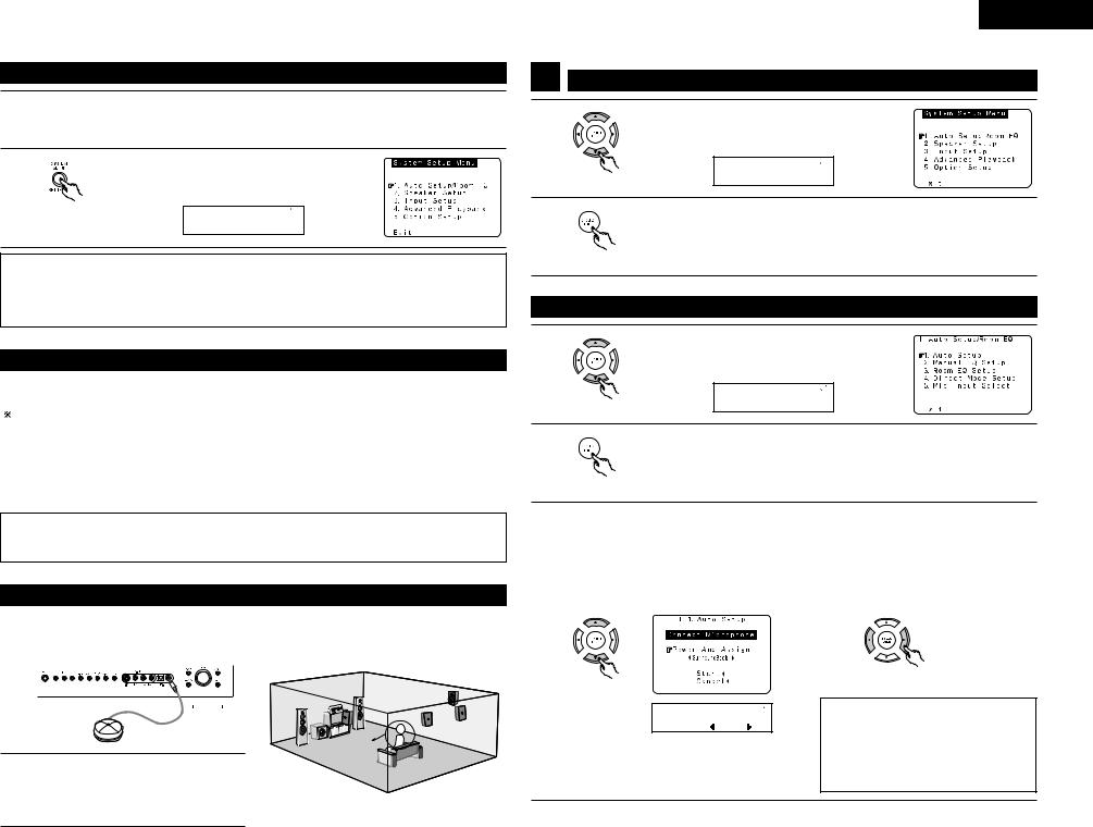
|
Before setting up the system |
1 |
Check that all the connections are correct, then turn on the main unit’s power. |
Setup will not be possible when the unit is set to Pure Direct ON or when the headphones are plugged |
|
|
in. Therefore, please cancel the mode or reverse the condition. |
2 |
Display the System Setup Menu. |
|
|
|
(Remote control unit) |
|
*System Setup |
|
Auto Set/RoomEQ |
NOTES:
•The System Setup menu composition is of a layered design that includes the related items below the large table title as contained in the tables of Pages 11 and 12.
•Wherever your position in System Setup, one more press of the System Setup button permits a move to one level higher.
Auto setup/Room EQ
The Auto Setup function of this unit performs an analysis of the speaker system and measures the acoustic characteristics of your room to permit an appropriate automatic setting.
When performing Auto Setup, a microphone is required for the setup.
2 Measurement and setting details
q Speaker Config.: |
This sets the speaker connection mode, polarity, and bass reproduction ability. |
|
w Delay Time |
: |
This sets the optimum delay time from each speaker corresponding to the listening position. |
e Channel Level |
: |
This sets the volume that is output from each speaker. |
r Room EQ |
: |
This sets the frequency response of each speaker. |
NOTE:
•A loud test tone is output during the measurement. Please consider this should you be planning nighttime measurements, and consider not allowing small children into the listening room at this time.
Connecting the microphone for Auto Setup
1 |
Connect the microphone for Auto Setup to the |
|
NOTE: |
||||||||||||
Setup Mic connector on the front panel of the |
• When using other microphone. (See page 16) |
||||||||||||||
|
unit. |
|
|||||||||||||
|
|
|
|
|
|
|
|
|
|
|
|
|
|
|
|
|
|
|
|
|
|
|
|
|
|
|
|
|
|
|
|
|
|
|
|
|
|
|
|
|
|
|
|
|
|
|
|
|
|
|
|
|
|
|
|
|
|
|
|
|
|
|
|
Listening position
2 |
Place the microphone for Auto Setup |
at |
the |
actual listening position which will be |
at |
the |
same height as your ears. Use a tripod or level surface at positioning.
ENGLISH
1 |
Setting the Auto Setup / Room EQ |
||
1 |
|
Select “Auto Setup / Room EQ” at the System Setup |
|
|
Menu. |
|
|
|
|
*System Setup |
|
|
(Remote control unit) |
Auto |
Set/RoomEQ |
2 |
|
|
|
|
Display the Auto Setup / Room EQ menu. |
||
|
|
||
|
(Remote control unit) |
|
|
1-1 Setting the Auto Setup |
|
||
1 |
|
Select “Auto Setup” at the Auto Setup / Room EQ |
|
|
Menu. |
|
|
|
|
*AutoSet/RoomEQ |
|
|
(Remote control unit) |
Auto |
Setup |
2 |
|
|
|
|
Display the Auto Setup screen. |
||
|
|
||
|
(Remote control unit) |
|
|
3 |
Check the “Power Amp Assign” setting. |
|
|
• When “Surround Back” is selected, the test tone during Auto Setup will be output from the |
|||
|
Surround Back speaker. |
|
|
|
• When “ZONE2” is selected, change the setting to ”ZONE2”. The test tone during Auto Setup is set |
||
|
so that it will not be output to ZONE2 (Another room). |
||
|
q Select the Power Amp Assign setting. |
w Select “Surround Back” or “ZONE2”. |
|
(Remote control unit)
*Auto Setup
P . Amp: SB
(Remote control unit)
NOTE:
•When “ZONE2” is selected at System Setup Menu “Power Amp Assign”, surround back speaker is not displayed as the target of setup in “2-1. Speaker Config.”. The results is reflected in “5-1. Power Amp Assign”.
13
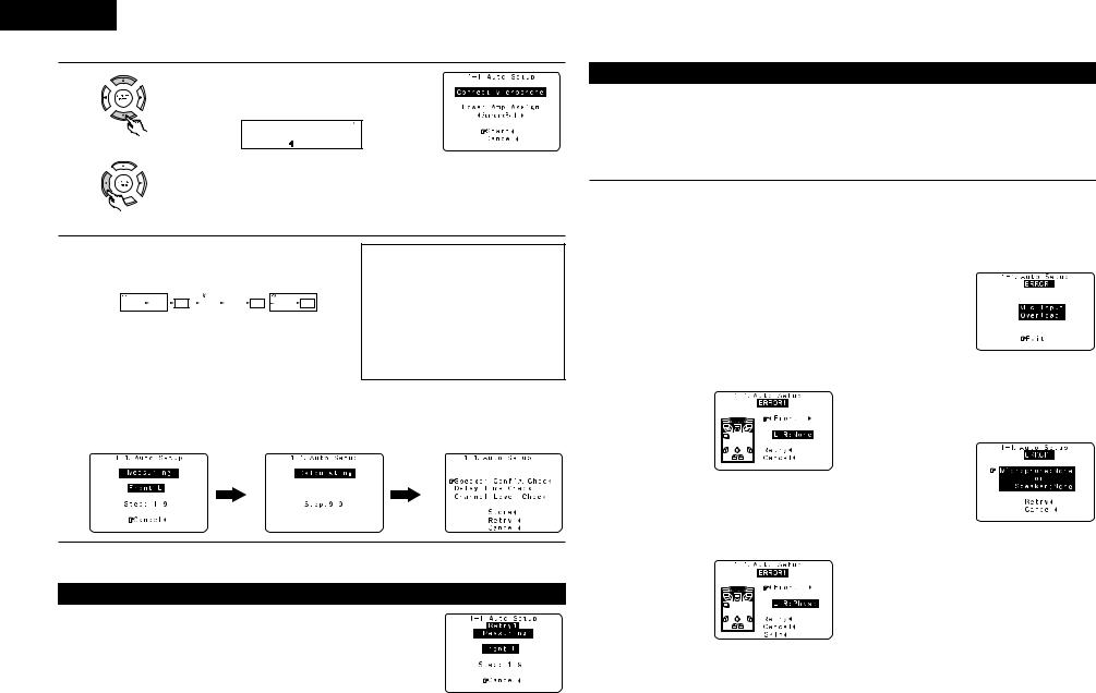
ENGLISH
4 |
|
q Select the “Start”. |
|
|
|
|
|
*Auto Setup |
|
(Remote control unit) |
Start |
|
|
w Press the CURSOR left button.
(Remote control unit)
5 |
Start the measurements. |
|
|
|
|
|
|
|
||||||||||||
Measurement of each channel is performed as follows. |
||||||||||||||||||||
|
Display |
|
|
|
|
|
|
|
|
|
|
|
|
|
|
|
||||
|
1 |
|
|
|
2 |
|
|
|
3 |
|
|
|||||||||
|
|
FL |
|
|
FR |
|
C |
|
|
SW |
|
|
SL |
|
SR |
|
|
SBL |
|
SBR |
|
|
|
|
|
|
|
|
|
|
|
|
|
||||||||

 1 Only the front speakers (A) is measured. Even if the front speakers (B) is set, the setting automatically switches to the front speakers (A) once measurements are completed.

 2 Subwoofer speaker is measured twice.

 3 When “ZONE2” is selected, this is not displayed. After each channel is measured, “Calculating” appears.
The display switches to Auto Setup check screen automatically.
NOTES:
•Measurement is canceled when MASTER VOLUME is operated while the Auto Setup is performed.
•Set the volume to halfway and set the crossover frequency to the maximum or low pass filter off if your subwoofer can adjust the output volume and the crossover frequency.
About automatic retry
Remeasurement starts automatically to receive proper result of measurement. Remeasurement is performed to 2 times, and “Retry1” or “Retry2” is displayed on screen during remeasurement.
About the error message
These error screens will be displayed when performing the measurements of Auto Setup / Room EQ and the automatic measurements can not be completed because of the speaker arrangement, measurement environment, or other factors. Please check the following matters, reset the pertinent items, and measure again. When there is too much noise in the room, the speakers may not be detected properly. Should this happen, perform the measurements when the noise level is low, or switch off the power of the equipment that is producing the noise for the duration of the measurements.
qThis screen will be displayed when the speakers required for producing suitable reproduction have not been detected.
•The front L and front R speakers were not properly detected.
•Only one channel of the surround speakers was detected.
•Sound was output from the R channel when only one surround back speaker was connected.
•The surround back was detected, but the
surround speaker was not detected.
Check that the pertinent speakers are properly connected.
(see page 9)
wThis screen will be displayed when the speaker polarity is connected in reverse.
Check the polarity of the pertinent speakers. For some speakers, the screen below may be displayed even though the speakers are properly connected. If so, select “Skip0”.
eThis screen will be displayed when accurate measurements cannot be made due to the input level to the microphone being too high.
Set up the speakers so that their position is farther away from the listening position. Lower the volume of the subwoofer.
rThis screen will be displayed when the measurement microphone is not connected, or when all of the speakers have not been detected.
Connect the measurement microphone to the microphone connector.
Check the speaker connections.
14

|
Check of the measurement results |
|
1 |
|
Select the items. |
|
The measurement results of each item can be checked |
|
|
|
here. |
|
|
*Auto Setup |
|
(Remote control unit) |
Sp Config . Check |
|
|
|
2 |
|
Press the ENTER button and display the verification |
|
screen. |
|
(Remote control unit)
NOTE:
•When measurements have been made using the measurement microphone, speakers with a built-in filter such as subwoofers might be set with a value that differs from the physical distance because of the internal electrical delay.
[Speaker Config. Check] |
[Delay Time Check] |
[Channel Level Check] |
|||||
|
|
|
|
|
|
|
|
|
|
|
|
|
|
|
|
|
|
|
|
|
|
|
|
|
|
|
|
|
|
|
|
|
|
|
|
|
|
|
|
|
|
|
|
|
|
|
|
|
|
|
|
|
|
|
|
|
|
|
|
|
|
|
|
|
|
|
|
|
|
|
|
|
|
|
|
|
|
|
|
|
|
|
|
|
|
|
|
|
|
|
|
|
|
|
|
3 |
If the check ends, press the ENTER button again. |
|
|
||
|
(Remote control unit) |
|
4 |
Select from the following three items based on the |
|
measurement results. |
||
|
• Store |
: Set with the checked measurement value. |
|
• Retry |
: Perform the measurement again. |
|
• Cancel : Cancel the checked measurement value. |
|
|
(Remote control unit) |
|
|
|
*Auto Setup |
|
|
Store |
5 |
When the “Store” is selected, all parameters are stored |
|
up. |
|
|
When the “Retry” is selected, it measures again.
(Remote control unit)
ENGLISH
1-2 Setting the Manual EQ Setup
Adjust the tone of the various speakers except subwoofer while listening to the sound (music).
1 |
Select “Manual EQ Setup” at the Auto Setup / Room |
||||
EQ Menu. |
|
|
|
|
|
|
*AutoSet/RoomEQ |
||||
(Remote control unit) |
Manual |
EQ |
Setup |
||
|
|
|
|
|
|
2 |
Display the Manual EQ Setup screen. |
||||
|
|||||
(Remote control unit) |
|
|
|
|
|
|
*ManualEQ |
Setup |
|
||
|
Channel |
: |
FL |
|
|
3 |
Select the speaker to be set. |
|
|
||
The display changes as follows. |
|
||||
|
FL |
FR |
|
C |
SL |
(Remote control unit) |
SBR |
SBL |
|
SR |
|
|
SB |
1spkr |
|
Flashing |
|
|
When the surround back speaker setting is set to |
||||
|
“1spkr” at “Speaker Configuration”, this is set to |
||||
|
“SB”. |
|
|
|
|
|
*ManualEQ |
Setup |
|||
4 |
Channel |
: |
FL |
|
|
Select the frequency. |
|
|
|
|
|
|
|
|
|
|
|
|
*ManualEQ |
Setup |
|||
(Remote control unit) |
63Hz |
: |
0 . 0dB |
|
|
|
|
|
|
|
|
5 |
Use the cursor left and right buttons to adjust the Gain |
||||
level. |
|
|
|
|
|
|
• Each frequency can be adjusted the range from –6 dB |
||||
|
to +6 dB in 0.5 dB step. |
|
|
|
|
(Remote control unit) |
|
|
|
|
|
6 |
Enter the setting. |
|
|
|
|
The Auto Setup / Room EQ Menu reappears. |
|||||
(Remote control unit)
15
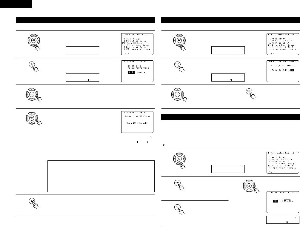
ENGLISH
1-3 Setting the Room EQ Setup
Select the setting of an Equalizer that has been set with Auto Setup or Manual EQ.
1 |
|
Select “Room EQ Setup” at the Auto Setup / Room EQ |
|
Menu. |
|
|
|
*AutoSet/RoomEQ |
|
(Remote control unit) |
Room EQ Setup |
2 |
|
|
|
Display the Room EQ Setup screen. |
|
|
|
|
|
(Remote control unit) |
|
|
|
*Room EQ Setup |
|
|
SurMode:ALL |
1-4 Setting the Direct Mode
Perform the ON/OFF setting of Room EQ when the surround mode is Direct or Pure Direct.
1 |
|
Select “Direct Mode Setup” at the Auto Setup / Room |
|
|
EQ Menu. |
|
|
|
|
*AutoSet/RoomEQ |
|
|
(Remote control unit) |
Direct |
Mode |
2 |
|
|
|
|
Display the Direct Mode Setup screen. |
||
|
|
||
|
(Remote control unit) |
|
|
|
|
*Direct |
Mode |
|
|
Room EQ |
: OFF |
3 |
Select All or Assign. |
3 |
Select ON or OFF. |
4 |
Enter the setting. |
||
• |
All |
: The Equalizer to all Surround mode is set as once. |
|
The Auto Setup / Room EQ |
|||
|
• |
Assign |
: The Equalizer to each surround mode is to set individually. |
|
|
|
Menu reappears. |
|
(Remote control unit) |
|
|
|
(Remote control unit) |
|
(Remote control unit) |
|
|
|
|
|
|
||
4 |
|
When the All is selected and press the ENTER button, |
|
|
||
|
display the Select the EQ Curve screen. |
|
|
|||
|
|
Select the Equalizer setting. |
|
|
||
|
|
• |
OFF |
: The Equalizer is not used. |
|
|
|
(Remote control unit) |
• |
Normal |
: Adjusts the frequency response of all |
|
|
|
|
|
speakers suitable for general surround |
|
|
|
|
|
|
|
|
|
|
|
|
|
|
system. |
|
|
|
|
• |
Front |
: Adjusts the characteristics of each |
*Room |
EQ Setup |
|
|
|
|
speaker to the characteristics of the front |
||
|
|
|
|
RoomEQ |
Normal |
|
|
|
|
|
speakers. |
|
|
|
|
|
|
|
|
|
|
|
• |
Flat |
: Adjusts the frequency response of all speakers flat. |
|
|
|
|
|
|
This is suitable for music reproduction like ITU-R speaker setting. |
||
|
|
• |
Manual |
: Selects the setting value that was set in the Manual EQ setup. |
||
NOTES:
•The Equalizer setting of Normal, Front and Flat can be selected after performing the Auto Setup.
•When the speaker set as “None” with the Auto Setup is change to on manually, the equalizer of “Normal”, “Front” and “Flat” cannot be used.
•The Equalizer setting can be selected by SURROUND PARAMETER button in Main unit or Remote control unit.
•When headphone is connected, the Room EQ cannot be used.
5 |
Enter the setting. |
The Auto Setup / Room EQ Menu reappears. |
(Remote control unit)
1-5 Setting the MIC Input Select
•Use this setting when using a microphone other than the included one for measurements when performing the auto setup procedure.
•The microphone included with the AVR-2805 is a measurement microphone designed specifically for use
during the auto setup procedure. Select “Mic” and connect the included microphone to the “SETUP MIC” mini-jack. When conducting the auto setup procedure using a separate high performance condenser microphone for measurements, select “V.AUX L” and connect the microphone to the “V.AUX Lch” pin jack. Please ask the DENON Authorized Service Center about the usable microphone other than the included one.
1 |
|
Select “Mic Input Select” at the Auto Setup / Room EQ |
|
||
|
Menu. |
|
|
|
|
|
|
*AutoSet/RoomEQ |
|
||
|
(Remote control unit) |
Mic |
In Select |
|
|
|
|
|
|
|
|
2 |
|
Display the Mic Input Select |
3 |
Select the Mic input jack or |
|
|
screen. |
|
V.AUX L jack. |
||
|
(Remote control unit) |
|
|
(Remote control unit) |
|
|
|
|
|
|
|
4 |
|
Enter the setting. |
|
|
|
|
The Auto Setup / Room EQ |
|
|
||
|
|
Menu reappears. |
|
|
|
|
(Remote control unit) |
|
|
|
|
|
|
|
|
|
*Mic In Select |
|
|
|
|
|
Mic |
16

ENGLISH
1-6 Check the EQ parameter
• The frequency characteristic of each speaker is rectified and the tone of the speaker is unified. The EQ parameters that were set in Auto Setup can be checked.
This item is automatically displayed, after the measurement result of the “Auto Setup / Room EQ” is decided.
1 |
|
Select “EQ Parameter Check” at the Auto Setup / Room |
||
|
EQ Menu. |
|
|
|
|
|
*AutoSet/RoomEQ |
|
|
|
(Remote control unit) |
Parameter |
Check |
|
2 |
|
|
|
|
|
Display the EQ Parameter Check screen. |
|||
|
|
|||
|
(Remote control unit) |
|
|
|
|
|
*ParameterCheck |
|
|
|
|
1:Normal |
|
|
3 |
Select the Equalizer curve. |
5 |
Select the speaker channel. |
|
|
|
|
(Remote control unit) |
|
(Remote control unit) |
|
|
4 |
Dislay the parameter screen. |
6 |
Enter the setting. |
(Remote control unit) |
(Remote control unit) |
7 |
If the check ends, select “Exit” |
and press the ENTER button. |
|
|
The Auto Setup / Room EQ |
|
Menu reappears. |
(Remote control unit) |
(Remote control unit) |
8
(Remote control unit) |
(Remote control unit) |
Select “Exit” and press the ENTER button at the Auto Setup / Room EQ Menu screen.
The System Setup Menu reappears.
17
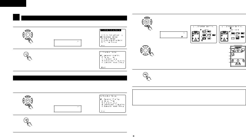
ENGLISH
2 Setting the Speaker Setup
• Crossover Frequency and Subwoofer Mode Setup is not displayed when not using a subwoofer.
1 |
|
Select “Speaker Setup” at the System Setup Menu. |
|
|
|
||
|
|
*System |
Setup |
|
(Remote control unit) |
Speaker |
Setup |
2 |
|
|
|
|
Display the Speaker Setup Menu screen. |
||
|
|
||
|
(Remote control unit) |
|
|
3 |
Set whether speakers are connected or not and, if so, their size parameters. |
q Select the speaker |
|
(Remote control unit) |
|
|
*Speaker Config |
|
FrontSp: Large |
|
w Select the parameter |
|
Center Sp. |
|
Front Sp. |
|
Subwoofer |
(Remote control unit) |
Surround Sp. |
|
Surround back Sp. |
2-1 Setting the type of speakers
•The composition of the signals output to each channels and the frequency response are adjusted automatically according to the combination of speakers actually being used.
1 |
|
Select “Speaker Config.” at the Speaker Setup Menu. |
|
|
|
||
|
|
*Speaker |
Setup |
|
(Remote control unit) |
Speaker |
Config . |
2 |
|
|
|
|
Display the speaker configuration screen as below. |
||
|
|
||
|
(Remote control unit) |
|
|
4 |
ENTER the setting. |
The Speaker Setup Menu reappears. |
(Remote control unit)
NOTE:
•Select “Large” or “Small” not according to the actual size of the speaker but according to the speaker’s capacity for playing low frequency (bass sound below the frequency set for the Crossover Frequency) signals. If you do not know, try comparing the sound at both settings (setting the volume to a level low enough so as not to damage the speakers) to determine the proper setting.
•Parameters
Large................. |
Select this when using speakers that have sufficient performance for reproducing bass |
|
sound below the frequency set for the Crossover Frequency mode. |
Small ................. |
Select this when using speakers that do not have sufficient performance for reproducing |
|
bass sound below the frequency set for the Crossover Frequency mode. When this is set, |
|
bass sound with a frequency below the frequency set for the Crossover Frequency mode is |
|
sent to the subwoofer. |
None…… .......... |
Select this when no speakers are installed. |
Yes/No… ........... |
Select “Yes” when a subwoofer is installed, “No” when a subwoofer is not installed. |
2spkrs/1spkr ..... |
Set the number of speakers to be used for the surround back channel. |
If the subwoofer has sufficient low frequency playback capacity, good sound can be achieved even when “Small” is set for the front, center and surround speakers.
18
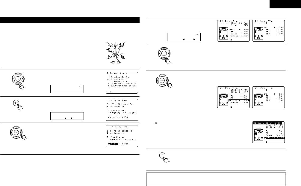
2-2 Setting the Delay Time
•Input the distance between the listening position and each speakers to set the delay time for the surround playback.
Preparations:
Measure the distances between the listening position and the speakers (L1 to L5 on the diagram at the right).
L1: Distance between center speaker and listening position L2: Distance between front speakers and listening position L3: Distance between surround speakers and listening position
L4: Distance between surround back speakers and listening position L5: Distance between subwoofer and listening position
FL |
Center |
|
FR |
Subwoofer |
L1 L2 |
|
|
|
L5 |
|
Listening position |
|
|
|
|
SL |
L3 |
L4 |
SR |
|
|||
SBL |
|
|
SBR |
1 |
|
Select “Delay Time” at the Speaker Setup Menu. |
||
|
|
|||
|
|
*Speaker |
Setup |
|
|
(Remote control unit) |
Delay |
Time |
|
2 |
|
|
|
|
|
Display the Delay Time screen. |
|||
|
|
|||
|
(Remote control unit) |
|
|
|
|
|
*Delay |
Time |
|
3 |
|
Meters |
: |
Feet |
|
Select the desired unit, meters or feet. |
|||
|
|
|||
(Remote control unit)
Example: When “Meters” is selected
ENGLISH
4 |
Once “Meters” or “Feet” is selected in step 3, |
||
the Delay Time screen appears automatically. |
|||
|
*Delay |
Time |
|
|
FL |
: |
3 . 6m |
5 |
|
Select the speaker to be set. |
|
|
The picture of the speaker selected blinks. |
||
|
(Remote control unit) |
|
|
6 |
|
Set the distance between the center speaker and listening position. |
|
|
The distance changes in units of 0.03 meters (0.1 foot) each time the button is |
||
pressed. Select the value closest to the measured distance.
(Remote control unit)
Example: When the distance is set to 3.6 m for the center speaker
If “Yes” is selected for “Default”, the settings are automatically reset to the default values.
Please note that the difference of distance for every speaker should be 6.0 m (20 ft) or less. If you set an invalid distance, a CAUTION notice, such as screen right will appear. In this case, please relocate the blinking speaker(s) so that its distance is no larger than the value shown in highlighted line.
7 |
Enter the setting. |
The Speaker Setup Menu reappears. |
The AVR-2805 automatically sets the optimum surround delay time for the listening
room.
(Remote control unit)
NOTE:
•If the distance unit is changed after the delay time is set, the settings are reset to the factory default values (see page 11).
19
 Loading...