


DRIVERACK PA

User Manual
Complete Equalization & Loudspeaker Control System
Featuring
Custom T unings
PA
®
WARNING FORYOUR PROTECTION
PLEASE READ THE FOLLOWING:
KEEP THESE INSTRUCTIONS
HEED ALL WARNINGS
FOLLOW ALL INSTRUCTIONS
DO NOT USE THIS APPARATUS NEAR WATER
CLEAN ONLY WITH A DRY CLOTH.
DO NOT BLOCK ANY OF THE VENTILATION OPENINGS. INSTALL IN ACCORDANCE WITH THE
MANUFACTURER’S INSTRUCTIONS.
DO NOT INSTALL NEAR ANY HEAT SOURCES SUCH AS RADIATORS, HEAT REGISTERS, STOVES,
OR OTHER APPARATUS (INCLUDING AMPLIFIERS) THAT PRODUCE HEAT.
ONLY USE ATTACHMENTS/ACCESSORIES SPECIFIED BY THE MANUFACTURER.
UNPLUG THIS APPARATUS DURING LIGHTNING STORMS OR WHEN UNUSED FOR LONG PERI-
ODS OF TIME.
Do not defeat the safety purpose of the polarized or grounding-type plug. A polarized plug
has two blades with one wider than the other. A grounding type plug has two blades and
a third grounding prong. The wide blade or third prong are provided for your safety. If
the provided plug does not fit your outlet, consult an electrician for replacement of the
obsolete outlet.
Protect the power cord from being walked on or pinched particularly at plugs, convenience receptacles, and the point where they exit from the apparatus.
Use only with the cart stand, tripod bracket, or table specified by the manufacture, or sold
with the apparatus. When a cart is used, use caution when moving the cart/apparatus
combination to avoid injury from tip-over.
Refer all servicing to to qualified service personnel. Servicing is required when the apparatus has been damaged in any way, such as power-supply cord or plug is damaged, liquid has been spilled or objects have fallen into the apparatus, the apparatus has been
exposed to rain or moisture, does not operate normally, or has been dropped.
POWER ON/OFF SWITCH: The Power switch used in this piece of equipment DOES NOT break
the connection from the mains.
MAINS DISCONNECT: The plug shall remain readily operable. For rack-mount or installation where plug is not accessible, an all-pole mains switch with a contact separation of at
least 3 mm in each pole shall be incorporated into the electrical installation of the rack or
building.
FOR UNITS EQUIPPED WITH EXTERNALLY ACCESSIBLE FUSE RECEPTACLE: Replace fuse with
same type and rating only.
MULTIPLE-INPUT VOLTAGE: This equipment may require the use of a different line cord,
attachment plug, or both, depending on the available power source at installation. Connect
this equipment only to the power source indicated on the equipment rear panel. To reduce
the risk of fire or electric shock, refer servicing to qualified service personnel or equivalent.
This Equipment is intended for rack mount use only.
SAFETY INSTRUCTIONS
NOTICE FOR CUSTOMERS IF YOUR UNIT IS EQUIPPED WITH A POWER CORD.
WARNING:THISAPPLIANCE MUSTBEEARTHED.
The cores in the mains lead are coloured in accordance with the following code:
GREEN and YELLOW - Earth BLUE - Neutral BROWN - Live
As colours of the cores in the mains lead of this appliance may not correspond with the coloured markings
identifying the terminals in your plug, proceed as follows:
• The core which is coloured green and yellow must be connected to the terminal in the plug
marked with the letter E, or with the earth symbol, or coloured green, or green and yellow.
• The core which is coloured blue must be connected to the terminal marked N or coloured black.
• The core which is coloured brown must be connected to the terminal marked L or coloured red.
This equipment may require the use of a different line cord, attachment plug, or both, depending on the
available power source at installation. If the attachment plug needs to be changed, refer servicing to qualified service personnel who should refer to the table below. The green/yellow wire shall be connected
directly to the units chassis.
WARNING: If the ground is defeated, certain fault conditions in the unit or in the system to which it is connected can result in full line voltage between chassis and earth ground. Severe injury or death can then
result if the chassis and earth ground are touched simultaneously.
The symbols shown above are internationally accepted symbols that warn of potential hazards with
electrical products. The lightning flash with arrowpoint in an equilateral triangle means that there
are dangerous voltages present within the unit. The exclamation point in an equilateral triangle indicates that it is necessary for the user to refer to the owner’s manual.
These symbols warn that there are no user serviceable parts inside the unit. Do not open the unit.
Do not attempt to service the unit yourself. Refer all servicing to qualified personnel. Opening the
chassis for any reason will void the manufacturer’s warranty. Do not get the unit wet. If liquid is
spilled on the unit, shut it off immediately and take it to a dealer for service. Disconnect the unit during storms to prevent damage.
IMPORTANT SAFETY INSTRUCTIONS
CAUTION
RISK OF ELECTRIC SHOCK
DO NOT OPEN
ATTENTION: RISQUE DE CHOC ELECTRIQUE - NE PAS OUVRIR
WARNING: TO REDUCE THE RISK OF FIRE OR ELECTRIC
SHOCK DO NOT EXPOSE THIS EQUIPMENT TO RAIN OR MOISTURE
CONDUCTOR
L
N
E
LIVE
NEUTRAL
EARTH GND
WIRE COLOR
Normal Alt
BROWN
BLUE
GREEN/YEL
BLACK
WHITE
GREEN

U.K. MAINS PLUG WARNING
A molded mains plug that has been cut off from the cord is unsafe.
Discard the mains plug at a suitable disposal facility. NEVER UNDER
ANY CIRCUMSTANCES SHOULD YOU INSERT A DAMAGED OR CUT
MAINS PLUG INTO A 13 AMP POWER SOCKET. Do not use the
mains plug without the fuse cover in place. Replacement fuse covers
can be obtained from your local retailer. Replacement fuses are 13
amps and MUST be ASTA approved
to BS1362.
LITHIUM BATTERY
WARNING
CAUTION!
This product may contain a lithium battery.There is danger of
explosion if the battery is incorrectly replaced.Replace only
with an Eveready CR 2032 or equivalent.Make sure the battery is installed with the correct polarity.Discard used batteries according to manufacturer’s instructions.
ADVARSEL!
Lithiumbatteri - Eksplosjonsfare.Ved utskifting benyttes kun
batteri som anbefalt av apparatfabrikanten. Brukt batteri
returneres apparatleverandøren.
ADVARSEL!
Lithiumbatteri - Eksplosionsfare ved fejlagtig håndtering.
Udskiftning må kun ske med batteri av samme fabrikat og
type. Levér det brugte batteri tilbage til leverandøren.
VAROITUS!
Paristo voi räjähtää,jos se on virheellisesti asennettu. Vaihda
paristo ainoastaan laitevalmistajan suosittelemaan tyyppin.
Hävitä käytetty paristo valmistajan ohjeiden mukaisesti.
VARNING!
Explosionsfara vid felaktigt batteribyte.Använd samma batterityp eller en ekvivalent typ som rekommenderas av apparattillverkaren.Kassera använt batteri enligt fabrikantens instruktion.
IMPORTANT SAFETY INSTRUCTIONS
ELECTROMAGNETIC
COMPATIBILITY
This unit conforms to the Product
Specifications noted on the Declaration of
Conformity. Operation is subject to the following two conditions:
• this device may not cause harmful interference, and
• this device must accept any interference
received, including interference that may
cause undesired operation.
Operation of this unit within significant electromagnetic fields should be avoided.
• use only shielded interconnecting cables.
DECLARATION OF
CONFORMITY
Manufacturer’s Name: dbx Professional Products
Manufacturer’s Address: 8760 S. Sandy Parkway
Sandy, Utah 84070, USA
declares that the product:
Product name: dbx DriveRack PA
Note: Product name may be suffixed by the EU.
Product option: None
conforms to the following Product Specifications:
Safety: IEC 60065 (1998)
EMC: EN 55013 (1990)
EN 55020 (1991)
Supplementary Information:
The product herewith complies with the requirements of the
Low Voltage Directive 72/23/EEC and the EMC Directive
89/336/EEC as amended by Directive 93/68/EEC.
Vice-President of Engineering
8760 S. Sandy Parkway
Sandy, Utah 84070, USA
Date: April 19,2002
European Contact: Your local dbx Sales and Service Office or
Harman Music Group
8760 South Sandy Parkway
Sandy, Utah 84070 USA
Ph: (801) 566-8800
Fax: (801) 568-7583

Table of Contents
DriveRack
™
PA
Introduction
0.1 Defining the DriveRack™ PA .........................ii
0.2 Service Contact Info ........................................iii
0.3 Warranty ...........................................................iv
Section 1 - Getting Started
1.1 Rear Panel ......................................................2
1.2 Front Panel .....................................................2
1.3 Quick Start .....................................................3
Section 2 - Editing Functions
2.1 Basic Navigation Modes.................................12
2.2 Button Array Overview..................................12
2.3 Navigating the EQ Section (GEQ/PEQ) ........14
2.4 Navigating the Subharmonic Synthesizer Section....14
2.5 Navigating the Crossover Section..................14
2.6 Navigating the Feedback Suppression Section ..15
2.7 Navigating the Comp/Limiter Section...........15
2.8 Navigating the Speaker Alignment Delay
Section..................................................................15
2.9 Navigating the Utility Section........................16
2.10 Navigating the Wizard Section ....................16
Section 3 - Operating the
DriveRack PA
3.1 Program Definition .........................................18
3.2 Navigating Factory Programs .........................18
3.3 Editing Factory Programs ...............................18
Section 4 - Detailed Parameters
4.1 Pre-Crossover Graphic EQ.............................22
4.2 Advanced Feedback Suppressor ...................22
4.3 Subharmonic Synthesizer...............................23
4.4 Crossover ........................................................24
4.5 Post-Crossover Parametric EQ.......................25
4.6 Compressor/Limiter........................................25
4.7 Speaker Alignment Delay .............................27
Section 5 - Application Guide
5.1 2X6 Crossover.................................................30
5.2 2X5 Crossover.................................................31
5.3 2X4 Crossover.................................................32
5.4 2X3 Crossover.................................................33
Appendix
A.1 Factory Reset .................................................36
A.2 Quick Key Options ........................................36
A.3 Specifications..................................................37
A.4 Auto EQ Optimization Tips ..........................37
A.5 Crossover Diagrams.......................................38
A.6 Block Diagram ...............................................39
A.7 Prog List/Speaker Tunings/Amp Tunings ....40
A.8 System Setup and Gain Structure .................41
DriveRack™ User Manual
Table of Contents
®
INTRO
CUSTOMER SERVICE INFO
Defining the DriveRack
WARRANTY INFO
®
INTRODUCTION
DriveRack
™
PA

Introduction
DriveRack™ PA User Manual
ii
DriveRack
™
PA
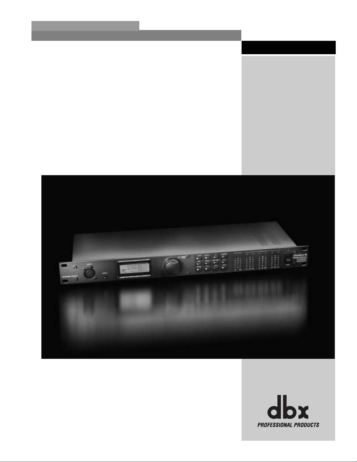
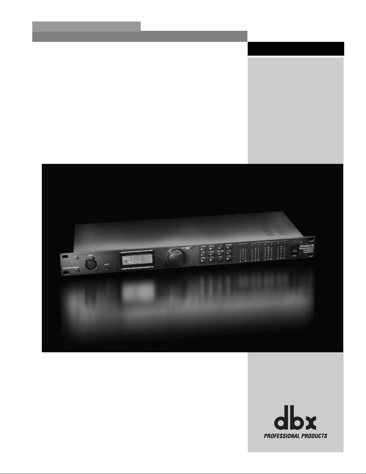
Drive your PA to a whole new level of performance with the DriveRack
TM
PA Complete
Equalization & Loudspeaker Control System. The DriveRack PA from dbx Professional Products
represents a complete integration of the key elements that help ensure optimal loudspeaker system management in P A-specific applications. Capitalizing on the legendary 480 DriveRack technology, the DriveRack PA is able to provide its user with top-tier, pro-level loudspeaker management specifications, yet still remain appealing to the budget-conscious audiophile who
requires a tried and true utilitarian workhorse. With its all-inclusive, no-compromise design, the
DriveRack PA has been systematically developed and designed to grow with your system needs
for years to come.
The dbx DriveRack™ PA is the most effective way to manage all aspects of Loudspeaker management for Public Address system applications. The DriveRack P A essentially becomes the only
device that you will need between the mixer and the power amps. The following are just some
of the features of the DriveRack™ PA.
DriveRack™ PA features:
• Stereo Feedback Elimination with 12 feedback notch filters
• Dual 28-band Graphic EQ
• Classic dbx®Compressor
• 120A Sub-harmonic Synthesizer
• 2x3, 2x4, 2x5, 2x6 Crossover Configurations
• Stereo Multi-band Parametric EQ
• Stereo Output Limiters
• Alignment Delay
• Pink Noise Generator
• Auto-EQ with 28-Band RTA
• JBL®Speaker and Crown®Power Amp Tunings with Setup Wizard
• 25 User Programs / 25 Factory Programs
• 2 Channel XLR Input and 6 Channel XLR Output
• Front panel RTA-M XLR input with phantom power
• 24-Bit ADC/24-Bit DAC, >110 dB Dynamic Range
• TypeIV®Conversion System
• Full Graphic LCD Display
0.1 Defining the DriveRack™ PA
INTRODUCTION
®

Introduction
DriveRack
™
PA
DriveRack™ PA User Manual
By including every form of processing necessary to drive the signal from the mixer to the power
amp, the DriveRack™ PA allows you to eliminate all other processing devices normally found
in large and cumbersome traditional drive rack systems of the past.
The DriveRack™ PA Loud Speaker Management System includes two balanced XLR inputs, as
well as six balanced XLR output connectors.
If you require technical support, contact dbx Customer Service. Be prepared to accurately
describe the problem. Know the serial number of your unit - this is printed on a sticker attached
to the top panel. If you have not already taken the time to fill out your warranty registration
card and send it in, please do so now.
Before you return a product to the factory for service, we recommend you refer to the manual. Make sure you have correctly followed installation steps and operation procedures. If you
are still unable to solve a problem, contact our Customer Service Department at (801) 568-7660
for consultation. If you need to return a product to the factory for service, you MUST contact
Customer Service to obtain a Return Authorization Number.
No returned products will be accepted at the factory without a Return Authorization Number.
Please refer to the Warranty information on the following page, which extends to the first enduser. After expiration of the warranty, a reasonable charge will be made for parts, labor, and
packing if you choose to use the factory service facility. In all cases, you are responsible for
transportation charges to the factory. dbx will pay return shipping if the unit is still under warranty.
Use the original packing material if it is available. Mark the package with the name of the shipper and with these words in red: DELICATE INSTRUMENT, FRAGILE! Insure the package properly. Ship prepaid, not collect. Do not ship parcel post.
0.2 Service Contact Info
iii
®

Introduction
DriveRack™ PA User Manual
iv
DriveRack
™
PA
This warranty is valid only for the original purchaser and only in the United States.
1. The warranty registration card that accompanies this product must be mailed within 30 days
after purchase date to validate this warranty. Proof-of-purchase is considered to be the burden of the consumer.
2. dbx warrants this product, when bought and used solely within the U.S., to be free from
defects in materials and workmanship under normal use and service.
3. dbx liability under this warranty is limited to repairing or, at our discretion, replacing defec-
tive materials that show evidence of defect, provided the product is returned to dbx WITH
RETURN AUTHORIZATION from the factory, where all parts and labor will be covered up to
a period of two years. A Return Authorization number must be obtained from dbx by telephone. The company shall not be liable for any consequential damage as a result of the product's use in any circuit or assembly.
4. dbx reserves the right to make changes in design or make additions to or improvements upon
this product without incurring any obligation to install the same additions or improvements
on products previously manufactured.
5. The foregoing is in lieu of all other warranties, expressed or implied, and dbx neither assumes
nor authorizes any person to assume on its behalf any obligation or liability in connection
with the sale of this product. In no event shall dbx or its dealers be liable for special or consequential damages or from any delay in the performance of this warranty due to causes
beyond their control.
0.3 W arranty
®
Getting Started
Section 1
DriveRack
™
PA
®
Getting Started
DriveRack™ PA User Manual
2
Section 1
DriveRack
™
PA
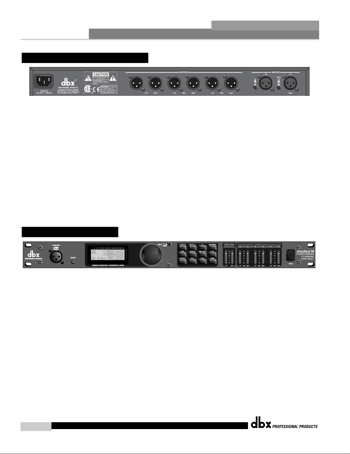
IEC Power Cord Receptacle
The DriveRack™ PA comes with a power supply that will accept voltages ranging from 100V120V at frequencies from 50Hz-60Hz. An IEC cord is included. EU version accepts 220V-240V
at frequencies from 50Hz-60Hz.
Outputs 1-6
The output section of the DriveRack™ PA offers six electronically balanced XLR connectors.
Inputs 1-2
The input section of the DriveRack™ PA offers two electronically balanced XLR connectors.
+4/-10dBv Switch
This switch changes the level from either +4 or -10dBv.
Ground Lift Switch
The ground lift switch lifts the pin 1 chassis ground of both input XLR connectors.
RT A Input Jack
This balanced XLR input is used for the connection of an RTA microphone, which allows the
user to “Pink” and optimize the EQ settings of any room through the use of the Auto EQ in the
Wizard setup assistant.
RT A MIC Input Selector
Pressing the RTA MIC input button will engage the front panel RTA input XLR connector.
Data Wheel
The Data wheel of the DriveRack™ PA is used to scroll through the program menu, load programs, select parameters and edit parameter values.
CROSSOVER/ALIGNMENT DELAY/GRAPHIC EQ/PARAMETRIC EQ/AUTO/EQ
1.2 Front Panel
1.1 Rear Panel Connections
Left/MonoLeft/Mono
®

LCD Display
The backlit LCD display of the DriveRack™ PA provides the user with all of the vital processing information of the DriveRack™ P A including: signal routing, effect block editing and Wizard
Setup functions. The display will also notify the user if any internal clipping is taking place
within the unit. The following message will appear: CLIP.
Function Buttons
The function buttons of the DriveRack™ PA allow direct access to all editing and navigating
functions of the DriveRack™ PA. The functions of the aforementioned buttons are as follows:
<PREV PG> - is used to navigate back through the various pages of any module block.
<NEXT PG> - is used to navigate forward through the various pages of any module block.
<EQ> - is used to move to the EQ modules. Successive presses will move you through the
EQ modules in the input section and through EQ modules located in the output section.
<SUBHARMONIC> - This button is used to move to the Subharmonic Synthesizer module.
<XOVER> - is used to move to the Crossover module.
<FEEDBACK> - is used to move to the feedback elimination module.
<COMP/LIMITER> - is used to move to the Compressor or Limiter modules.
<DELAY> - is used to move to the Delay module.
<PROGRAM> - is used to enter program mode when pressed.
<UTILITY> - is used to access the the Utility menu.
<STORE> - is used to store any program changes.
<WIZARD> - is used to enter the Wizard section which includes: SYSTEM SETUP, AUTO EQ
WIZARD and AFS WIZARD.
Input Meters
The DriveRack™ PA provides the user with two independent six segment Lightpipe™ input
meters that range from -30 to +20 dBu. These meters monitor the signal level right after the
input module.
Threshold Meters
The threshold meters indicate that the threshold level has been exceeded within the Limiter section, and gain reduction may be taking place within the specific output channel.
Output Meters
The DriveRack™ PA provides the user with six independent six-segment Lightpipe™ output
meters that range from -30 to +20 dBu.
Power Switch
The Power Switch turns the DriveRack™ PA on and off. Note: dbx Professional Products
strongly recommends that power amplifiers connected to the DriveRack™ PA, should be powered down prior to cycling the power on the DriveRack™ PA.
For those of you that wish to jump right in, the following information has been provided to
act as a quick start guide for optimizing performance of the DriveRack™ PA.
1.3 Quick Start
Getting Started
Section 1
DriveRack
™
PA
DriveRack™ PA User Manual
3
®
Getting Started
DriveRack™ PA User Manual
4
Section 1
DriveRack
™
PA
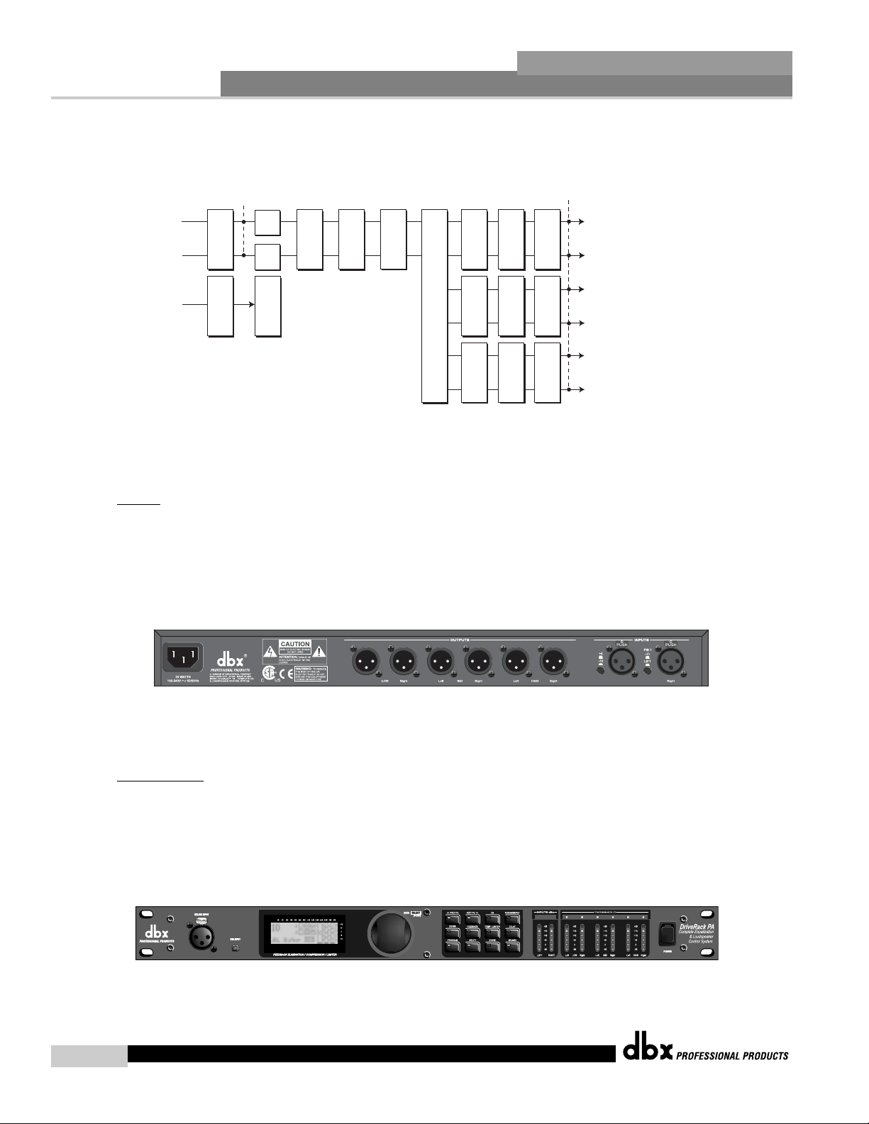
Signal Path Block Diagram
The following diagram shows the logical and intuitive signal path of the input, effect modules, and output of the DriveRack™ PA.
Connections
• When setting up the DriveRack™ PA, make connections as follows:
• Always make connections prior to applying power to the unit.
• Connect the output from the sending device (mixer) to either of the two XLR
inputs connectors shown below.
• Make output connections from any one of the six output XLR connectors shown
below to the input of the selected power amps.
• If you will be “pinking” the room through the use of the RTA, connect the selected
RTA microphone to the front-panel XLR input, and press the RTA input button.
• IMPORTANT- It is imperative that the power amps are turned off prior to cycling power to the Driverack™
PA. Always make sure that your power amps are the last item turned on and the first turned off.
Once all of the connections have been made and the unit is powered up, you can
navigate through the entire signal path of the DriveRack PA from the front panel of
the unit. The display provides you with a clear and concise overview of each aspect
of the signal path from the input to the output section.
The features of the front panel of the DriveRack™ PA are as follows from left to right.
RTA MIC Input- This XLR input is used for the connection of a RTA microphone.
Meters
Outputs
Alignment Delay Alignment Delay Alignment Delay
Left High
Left Input
Stereo/Mono
Pink Noise
Meters
SubHarmonic Synth
GEQ
AFS Notch Filters
Stereo Compressor
3-Band PEQ 2-Band PEQ 2-Band PEQ
Peak Stop Limiter Peak Stop Limiter Peak Stop Limiter
Right Input
Mic Input
Micr Pre amp
GEQ
RTA
Crossover Section - (2X3, 4,5,6)
Right High
Left Mid
Right Mid
Left Low
Right Low
Left/MonoLeft/Mono
CROSSOVER/ALIGNMENT DELAY/GRAPHIC EQ/PARAMETRIC EQ/AUTO/EQ
®
The RTA MIC input button is used to engage the RTA input connector. LCD Display-
All operational information of the DriveRack™ PA is displayed here. The display will
also notify the user if any internal clipping is taking place within the unit. The following message will appear: CLIP. Data Wheel - The data wheel is used to scroll through
the program menu of the DriveRack™ PA. The Data Wheel is also used to perform editing functions to effects and utility menu features. Button Array - Operational editing is
done using this 12 button array. A complete description of each button’s functionality is
listed below. Input meters- These two 6-segment LED meters monitor the input level
of the DriveRack™ PA directly after the input mixer. Output meters - These six 6-segment meters monitor the output levels of the DriveRack™ PA directly after the output
gain stage. Threshold meters - These six 1-segment meters (when lit) show that
threshold level of the limiters has been exceeded.
DriveRack PA Wizard
Now that you have made all of your audio connections and have made yourself familiar with
the front-panel navigation of the unit, you can easily optimize your system through the use of
the DriveRack™ PA Wizard setup system. This feature of the DriveRack™ PA allows for quick
and hyper-accurate venue setups. The menu section of the Wizard offers System setup, Auto
EQ and AFS (Advanced Feedback Suppression). The following will walk you through your
venue setup.
• From program mode, press the <WIZARD> button and the display will appear as
follows:
System Setup
• The arrow will indicate the selected Wizard setup. To select any one of the three
options, rotate the <DATA> wheel. If you are performing the System setup, press
either the <NEXT PG> button or the <DATA> wheel and the display will appear as
follows:
• Simply rotate the <DATA> wheel to select either a Mono or Stereo input configura-
tion. Once you have selected your input option, press the <NEXT PG> button and
the display will appear as follows:
Getting Started
Section 1
DriveRack
™
PA
5
DriveRack™ PA User Manual
DriveRack PA WIZARD
System Setup
Auto EQ WIZARD
AFS WIZARD
Input Setup
Select Input as MONO
or STEREO.
>STEREO
®

Getting Started
6
Section 1
DriveRack
™
PA
• Simply rotate the <DATA> wheel to select either a Dual Mono or Stereo linked 28-band
Graphic EQ. Once you have selected your EQ option, press the <NEXT PG> button and
the display will appear as follows:
• Rotate the <Data> wheel to select any one of the numerous custom-tuned MAIN speaker
options available. If the speaker being used is not specified in the menu, select CUSTOM.
Once you have selected your Main speaker option, press the <NEXT PG> button and the
display will appear as follows:
• Rotate the <Data> wheel to select any one of the numerous custom-tuned SUB speaker
options available. Once you have selected your SUB speaker option, press the <NEXT PG>
button and the display will appear as follows:
• You are now prompted to select a power amp by rotating the <DATA> wheel to select any
one of the numerous custom-tuned Amplifier options available. Note that the top line of the
display will either read High, Mid or Low depending on your selected speaker setup selections. Once you have selected your Amp tuning option (depending on the amp type), you
will select the specified amplifier sensitivity setting if applicable.
• Rotate the <DATA> wheel to select the amplifier manufacturer’s specified amplifier sensitivity
setting. Once set, press the <NEXT PG> button, and you will now be given the option of
optimizing your amp levels with the DriveRack PA. The page will appear something like this:
DriveRack™ PA User Manual
Graphic EQ Setup
Select GEQ as Dual
Mono or Stereo
>Dual Mono
Main Speaker
Select Main PA
JBL SRX
>SR4702X Passive
Sub Speaker
Select Sub PA
>None
High Amplifier
Select an amplifier
>Crwn MacroTech 1202
High Amplifier
Select Sensitivity
Crwn MacroTech 1202
>0.775 Volts
High Amp Level
Adjust level
same as your amp
>25
®
• You will now rotate the <DATA> wheel to match the same setting as your amplifier
of choice. Note that based on your amp selection, the DriveRack™ PA will initially
display the recommended setting of that particular amp for obtaining maximum
headroom. This is done to match unity gain from the DriveRack™ PA and your
amplifier. Note that if Sub Speakers are included in the speaker selection, you will
be asked if the sub woofer is bridged or mono. For more information regarding
Amplifier gain settings, please refer to the System Setup and Gain Structure information
located in the appendix section.
• Once you have completed your amp level settings, you will press the <NEXT PG>
button, where you will be asked to select a bridged or normal setting fro your low
amp (if used). The display will appear as follows:
• Once have made a bridged or mono selection, press the <NEXT PG> where the
unit will prompt <DATA> wheel to load your new settings. If you do not wish to
load the settings either press the <PROGRAM> button or use the <PREV PG> but-
ton to re-edit your settings, By using your selections, the DriveRack™ will automatically generate a new program and speaker selection which are used to choose the
correct crossover type, parameters, speaker compensation EQ and delay are also
adjusted by the speaker selection. Amplifier parameters are used to set the limiters
to stop amplifier clipping and balance out the crossover levels. You may find that
you want to re-adjust the crossover levels based on your taste and type of music.
Auto EQ WIZARD
• Once you have custom-tailored your system setup, you can now proceed to EQ your
system.The Auto EQ Wizard automatically adjusts the response of the system by producing pink noise and adjusting the Graphic EQ until the RTA matches a selected
response. From the DriveRack™ PA Wizard menu, rotate the <DATA> wheel until
the display appears as follows:
• Either press the <NEXT PG> button or rotate the <DATA> wheel and the display
will read:
• The display is prompting you to connect an RTA-specific microphone to the front-
Getting Started
Section 1
DriveRack
™
PA
7
DriveRack™ PA User Manual
Low Amp Bridging
Select
same as your amp
>Normal
DriveRack PA WIZARD
System Setup
Auto EQ WIZARD
AFS WIZARD
Auto EQ
Connect mic to RTA
input. Press RTA
input button.
®
Getting Started
8
Section 1
DriveRack
™
PA
panel RTA XLR input, and press the <RTA Input> button. It is recommended that you use the
optional dbx RTA-M microphone. If you wish to bypass the previous
steps all together, from program mode, press the <RTA Input> button, or press the <NEXT
PG> button and the display will appear something like this:
• You can now select any one of the several different Frequency responses for the Auto EQ.
The options are: Flat (0), and Response A-D, and Low, Medium and High Precision. Once
you have selected your desired EQ Frequency response, press the <NEXT PG> button and
the display will appear as follows:
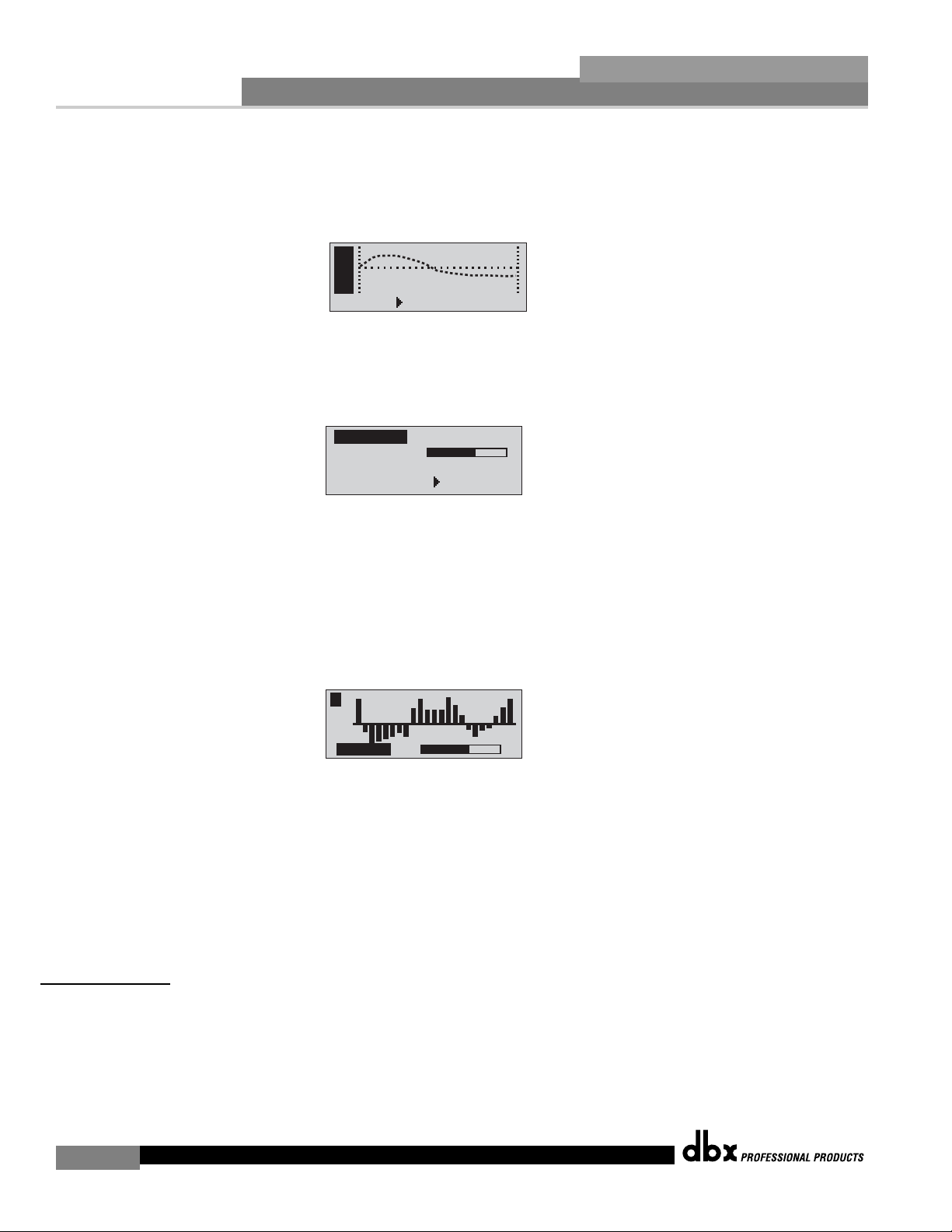
• You will now proceed to “Pink” the room by adjusting the Pink level. The range of bar graph
is -30dBu to +20dBu. Be certain to raise the pink noise level to the level to be used during
the performance. Once the Pink level has been adjusted to the desired volume, press the
<NEXT PG> button and the Auto EQ sequence will begin. The display will either show the
graphic EQ or the RTA. Rotating the <DATA> wheel clockwise and counter clockwise will
toggle between the two modes. You can also select either mode to default to in the Utility
menu. Regardless, the display will appear something like this:
• At this point, the DriveRack™ PA will automatically EQ the room. If you are using independent left and right graphic EQs, you will auto EQ each side independently. If you are using
a stereo-linked EQ, both sides will be EQ’d simultaneously. Auto EQ can be aborted at any
point in the process by pressing the <NEXT PG> button. Upon completion of the Auto EQ
Wizard, you can return to program mode by releasing the <RTA Input> button and pressing
the <PROGRAM> button.
For more information regarding the Auto EQ section, please refer to the Auto EQ Optimization
Tips information located in the Appendix section.
AFS WIZARD
• The DriveRack™ PA also offers its exclusive AFS (Advanced Feedback Suppression) module.
This unique feature now makes unwanted feedback in a PA system a thing of the past. The
AFS Wizard will lead you through the setup of of the fixed filters of the AFS module. From
DriveRack™ PA Wizard menu, rotate the <DATA> wheel until the display appears as follows:
DriveRack™ PA User Manual
A
E
u
Q
t
o
RESPONSE C PRECISION LOW
Auto EQ : Pink Noise
Mic Level
Turn Up Level
Pink Level > 18dB
L R
Auto EQ
®
 Loading...