


1260/1261
 User Manual
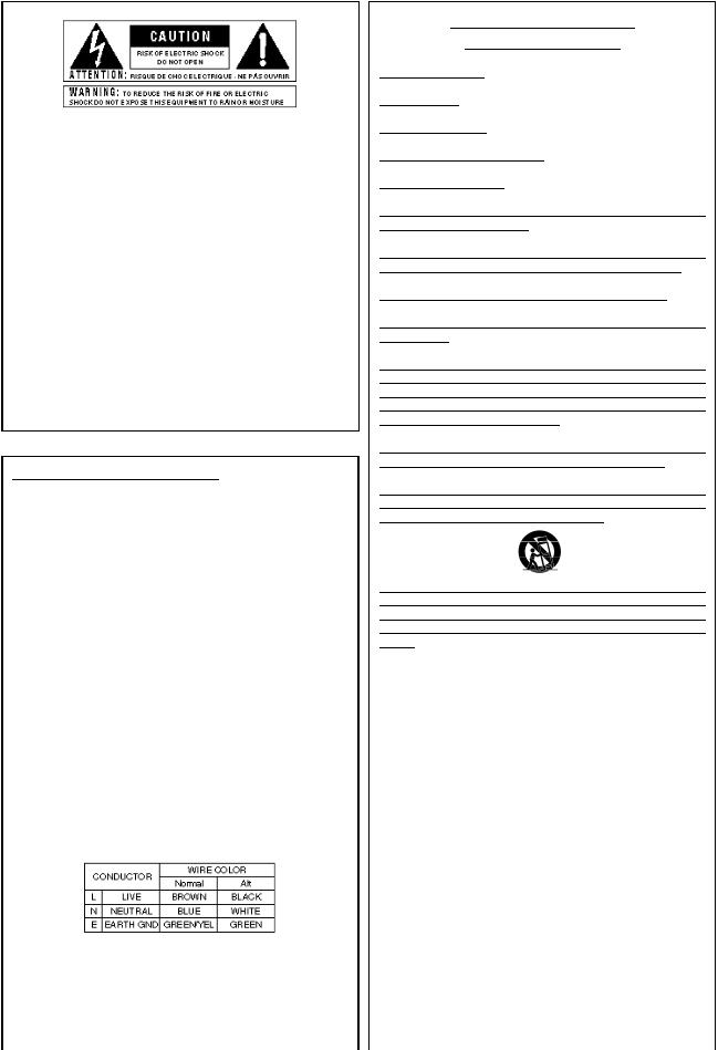
IMPORTANT SAFETY INSTRUCTIONS

IMPORTANT SAFETY INSTRUCTIONS

Introduction
ZonePRO™
Introduction |
|
|
0.1 |
ZonePro Features ............................................. |
ii |
0.2 |
Service Contact Info ........................................ |
iii |
0.3 |
Warranty ........................................................... |
iv |
Section 1 - Getting Started |
|
|
1.1 |
Rear Panel Connections ................................... |
2 |
1.2 |
(1260)Front Panel ............................................. |
3 |
1.3 |
(1261)Front Panel ............................................. |
3 |
1.4 |
ZonePRO Designer GUI .................................. |
4 |
1.5 |
Software Installation......................................... |
4 |
Section 2 - Software Overview |
|
|
2.1 |
ZonePRO Philosophy....................................... |
6 |
2.2 |
Views................................................................. |
6 |
2.3 |
Venue View Functions ..................................... |
6 |
2.4 |
Unit View Functions......................................... |
8 |
2.5 |
Module View Functions ................................. |
10 |
Section 3 - Software Operation |
|
|
3.1 |
Overview......................................................... |
12 |
3.2 |
Connecting to the Device .............................. |
12 |
3.3 |
Configuration Wizard ..................................... |
12 |
3.4 |
Parameter Editing ........................................... |
16 |
3.5 |
Storing Scenes................................................. |
17 |
3.6 |
Scene Wizard .................................................. |
17 |
3.7 |
Schedule Wizard............................................. |
18 |
3.8 |
File Save.......................................................... |
18 |
3.9 |
Hardware Navigation ..................................... |
18 |
Section 4 - Detailed Parameters |
||
4.1 |
Input................................................................ |
20 |
4.2 |
Parametric EQ................................................. |
20 |
4.3 |
Advanced Feedback Suppression (AFS) ....... |
21 |
4.4 |
Automatic Gain Control (AGC) ..................... |
23 |
4.5 |
Noise Gate ...................................................... |
24 |
4.6 |
Compressor ..................................................... |
25 |
4.7 |
De-Esser .......................................................... |
27 |
4.8 |
Notch Filters.................................................... |
28 |
4.9 |
Router/Mixer ................................................... |
28 |
4.10 Auto Warmth................................................. |
30 |
|
4.11 Band Pass Filter/Crossover ......................... |
31 |
|
4.12 Output Dynamics ......................................... |
32 |
|
4.13 Delay ............................................................. |
33 |
|
4.14 Output Polarity ............................................. |
33 |
|
Section 5- Application Guide |
|
|
5.1 |
Restaurant Install ............................................ |
36 |
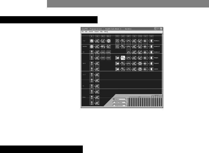
5.2 |
Health Club..................................................... |
38 |
5.3 |
Night Club....................................................... |
40 |
Section 6- Application Notes |
|
|
6.1 |
Using the Input Link Bus............................... |
44 |
6.2 |
Using the ZC as a Scene Selector ................. |
44 |
6.3 |
Using the ZC-Fire ........................................... |
44 |
6.4 |
Using the Locate Function ............................. |
45 |
6.5 |
Using the Address Network Wizard.............. |
45 |
Appendix |
|
|
A.1 Factory Reset/Flash Update........................... |
50 |
|
A.2 Specifications.................................................. |
51 |
|
A.3 Block Diagram ............................................... |
52 |
|
A.4 Link I/O.......................................................... |
53 |
|
A.5 Zone Controller Wiring and Install............... |
54 |
|
A.6 Network Overview ........................................ |
57 |
|
A.7 Copyright........................................................ |
64 |
|
Table of Contents ZonePRO™ User Manual

ZonePRO™
INTRODUCTION
INTRO
CUSTOMER SERVICE INFO
Defining the
ZonePRO
WARRANTY INFO

Introduction
ZonePRO™
Congratulations on your purchase of the dbx® ZonePRO 1260 and/or 1261! The ZonePRO prod- INTRODUCTION ucts are based on the same unparalleled design philosophy that made the DriveRack family
famous. This philosophy, “To provide everything you need between the sources and the amplifiers,” creates a full featured processor capable of almost any BGM or commercial audio application.
This manual will be your guide to understanding the full functionality of the powerful ZonePRO units By combining the different components, the configuration possibilities are limitless. After you have become familiar with the unit, we encourage you to experiment and find the most effective and efficient way to run your system by utilizing the powerful processing of the ZonePRO 1260 and 1261.
0.1 - ZonePro Features
ZonePRO 1260/1261 features:
•Individual Zone Routing or Mixing
•Advanced Feedback Suppression (AFS™)
•AutoWarmth®
•Auto Gain Control
•Compression
•Limiting
•Noise Gating
•Notch Filtering
•Bandpass and Crossover Filters
•Parametric EQ
•Security Lockout
•Wall Panel Control
•RS-232 and Ethernet Control
•IEC, UL, and CSA Certified
ii
ZonePRO™ User Manual

ZonePRO™
Introduction
In addition to the processing available, the ZonePRO units provide intuitive wall-panel control from the dbx Zone Controller (ZC) series. The ZC-1 and ZC-6 offer remote programmable Volume control to any installation using the ZonePRO units. The ZC-2 provides programmable Volume and Mute control. The ZC-3 and ZC-4 allow Source selection, Scene selection or Page steering. ZC-FIRE provides an interface for fire safety systems. The ZC-7 remote offers page steering from a programmable push button interface. The ZC-8 provides a single panel with both push button volume control and source selection. The ZC-9 provides source selection. Up to 12 Zone Controllers can be used with a single ZonePRO, and can either be wired in series or parallel. The ZC-BOB was created to accommodate “home-run” or parallel wiring to the unit. With a maximum length of 1,000 ft., the Zone Controllers offer a simple way to create a simple yet elegant solution to many installation applications.
ZC-BOB |
ZC-1 |
ZC-2 |
ZC-3 |
ZC-4 |
|
|
|
|
ZC-Fire |
ZC-6 |
ZC-7 |
ZC-8 |
ZC-9 |
0.2 - Service Contact Info
If you require technical support, contact dbx Customer Service. Be prepared to accurately describe the problem. Know the serial number of your unit - this is printed on a sticker attached to the top panel. If you have not already taken the time to fill out your warranty registration card and send it in, please do so now.
Before you return a product to the factory for service, we recommend you refer to the manual. Make sure you have correctly followed installation steps and operation procedures. If you are still unable to solve a problem, contact our Customer Service Department at (801) 568-7660 for consultation. If you need to return a product to the factory for service, you MUST contact Customer Service to obtain a Return Authorization Number.
No returned products will be accepted at the factory without a Return Authorization Number.
ZonePRO™ User Manual
iii

Introduction
ZonePRO™
Please refer to the Warranty information on the following page, which extends to the first enduser. After expiration of the warranty, a reasonable charge will be made for parts, labor, and packing if you choose to use the factory service facility. In all cases, you are responsible for transportation charges to the factory. dbx will pay return shipping if the unit is still under warranty.
Use the original packing material if it is available. Mark the package with the name of the shipper and with these words in red: DELICATE INSTRUMENT, FRAGILE! Insure the package properly. Ship prepaid, not collect. Do not ship parcel post.
0.3 - Warranty
This warranty is valid only for the original purchaser and only in the United States.
1.The warranty registration card that accompanies this product must be mailed within 30 days after purchase date to validate this warranty. Proof-of-purchase is considered to be the burden of the consumer.
2.dbx warrants this product, when bought and used solely within the U.S., to be free from defects in materials and workmanship under normal use and service.
3.dbx liability under this warranty is limited to repairing or, at our discretion, replacing defective materials that show evidence of defect, provided the product is returned to dbx WITH RETURN AUTHORIZATION from the factory, where all parts and labor will be covered up to a period of two years. A Return Authorization number must be obtained from dbx by telephone. The company shall not be liable for any consequential damage as a result of the product's use in any circuit or assembly.
4.dbx reserves the right to make changes in design or make additions to or improvements upon this product without incurring any obligation to install the same additions or improvements on products previously manufactured.
5.The foregoing is in lieu of all other warranties, expressed or implied, and dbx neither assumes nor authorizes any person to assume on its behalf any obligation or liability in connection with the sale of this product. In no event shall dbx or its dealers be liable for special or consequential damages or from any delay in the performance of this warranty due to causes beyond their control.
iv
ZonePRO™ User Manual

ZonePRO™ |
Section 1 |
Getting Started

|
|
|
™ |
|
Section 1 |
Getting Started |
ZonePRO |
|
|
|
|
|
|
|
1.1 - Rear Panel (1260 and 1261)
1. IEC Power Cord Receptacle
The ZonePRO 1260/1261 comes with a power supply that will accept voltages ranging from 100V-240V at frequencies from 50Hz-60Hz. An IEC cord is included.
2. S/PDIF Connection
This RCA connection is used to connect up to two digital input channels in the 1260/1261.
3. PC Connection (DB-9)
This DB-9 connection is used to communicate to the PC GUI and uses RS-232 protocol. This connection requires a Null modem cable and one is included with the ZonePRO unit.
4. Ethernet Connection (RJ-45)
This RJ-45 connection is used to control the unit via Ethernet.
5. Zone Control Inputs 1-12 (RJ-45)
This input connection is used to send information and power to the ZC wall controllers.
6. Outputs Channels 1-6 (Euroblock)
The output section of the ZonePRO offers six electronically balanced Euroblock connectors.
7. Input Link Buss (RJ-45)
The ZonePRO offers an input buss that duplicates the first six inputs from one unit to the next for applications requiring more than six output zones.
8. Input Source Channels 1-8 (RCA)
The input section of the ZonePRO offers eight mono-summing unbalanced RCA connectors.
9. Line/Mic Selector
This switch is used to select either the line or microphone input.
10. Signal/Clip LED
This LED is used to indicate microphone signal input or clip.
11. Mic/Line Inputs 1-2 (Euroblock)
The input section of the ZonePRO provides two Euroblock connectors for mic/line inputs.
12. Mic Gain Control
This knob is used to set the input gain for the microphone input.
2 |
ZonePRO™ User Manual |
|
|
ZonePRO™ |
Getting Started |
Section 1 |
||
|
|
|
|
|
|
|
1.2 - Front Panel (1260) |
|
|
1. LCD Display
The backlit LCD display of the ZonePRO 1260 provides the end-user with all the necessary controls including source selection, page steering, zone volume and mute.
2. Parameter Select 1-3
These three buttons are used to select and edit parameters.
3. Data Wheel
The Data Wheel is used to edit parameter values.
4. Page Buttons 1-2
The Page buttons are used to select the page mic path and steer it to selected zones.
5. Zone Select
These buttons are used to select output zones for front panel control.
6. Output Meters
The ZonePRO 1260 provides the user with six independent six-segment Lightpipe output meters that range from -30 to +20 dBu.
7.Threshold Meters
The threshold meters indicate that the threshold level has been exceeded within the output Compressor, Auto Gain Control, or Limiter sections, and gain reduction may be taking place.
1.3 - Front Panel (1261)
1. PC Connection
This DB-9 connection is used to communicate to the PC via RS-232 protocol.
2. Network Traffic LED
This LED is used to indicate Network Traffic; it is also used to indicate and identify the unit when the Locate function is enabled.
3. Power LED
This LED (when lighted), indicates that the ZonePRO 1261 is currently powered.
ZonePRO™ User Manual |
3 |
|
|
|
|
™ |
Section 1 |
Getting Started |
ZonePRO |
|
|
1. 4 - ZonePRO Designer GUI
The ZonePro Designer Graphic User Interface (GUI) provides all the control functions necessary to configure and program the ZonePro products. The GUI provides network tools for configuring your control network as well as multiple “Wizard” functions for configuring the system routing, implementing end-user control surfaces, programming parameters, and even creating automatic system changes. Understanding the ZonePro Designer software is the key to getting full functionality from ZonePro products.
1.5 - Software Installation
Minimum System Requirements for ZonePRO Designer are:
1 GHz or faster processor Windows 2000 or XP
256 MB RAM or (512 MB Recommended)
Recommended screen resolution: 1024 x 768 pixels or higher
Installation
•Install the ZonePRO GUI software from either the dbx website at www.dbxpro.com or from the included CD ROM onto your computer.
•Once the software setup is downloaded, double click on the file named: ZonePRO setup.
•The application will proceed to prompt you for the installation location.
•Once the software installation has been completed, it is recommended that you restart your computer.
Note
You must disable virus protection software during the installation of
ZonePRO Designer.
4 |
ZonePRO™ User Manual |
|
|

ZonePRO™ |
Section 2 |
|
|
SOFTWARE
OVERVIEW

|
|
|
|
™ |
Section 2 |
|
Software Overview |
ZonePRO |
|
|
|
|
||
|
For your convenience, |
all the configuration and editing features of the ZonePRO™ 1260 and |
||
|
1261 are performed via the included ZonePRO Designer GUI. This section has been created to |
|||
|
act as a tutorial for performing various editing aspects of the unit. |
|||
2. 1 - ZonePRO Philosophy
The philosophy of the ZonePRO Designer and the files that it creates, are built around the concept of a configuration, a scene and a device file; all of which are found in the Unit View (Please see below).
Configuration
The configuration includes all of the processing blocks, the I/O configuration, and the zone controllers. The configuration is set up by going through the Configuration Wizard. The ZonePRO device can only have one configuration, so all configuration editing must be completed before you can store any scenes. For more information on the configuration see Configuration Wizard in section 3.3.
Scenes
A scene consists of the parameters for all the modules and the assignment of zone controllers to a zone. The ZonePRO products allow switching of scenes from the Real Time Clock, or from a ZC zone controller. Up to 50 scenes can be stored in the ZonePRO unit. Scenes can be stored by clicking on the Store Scene button in the Unit view. For more information on scenes, see section 3.5.
Device
The configuration, scenes, and schedule information can all be stored off to a device file or .zpd (ZonePRO device). Storing a device file to the computer and then recalling it into another ZonePRO unit allows for exact duplication of a system in a single file download. The device file can be stored by selecting File Save in the Unit view.
2. 2 - Views
There are three different views within the ZonePRO Designer GUI; Venue view, Program screen, and Module view. Venue view Venue View gives you a global view of the network including all your units if you are using Ethernet control. Double clicking on a unit icon in the Venue view take you to the Unit view. Unit View (sometimes called program screen) provides you with a graphic representation of the configuration of the individual ZonePRO unit, including all the processing modules and their positions in the signal path. The program screen also offers access to meters, scene storing and loading, the Wizard functions, and file storing. Double clicking on the processing modules take you to the Module view. Module view (also called edit screen) provides access to the processing parameters. Editing of parameters is done in Module view.
2.3 - Venue View Functions
2.3.1Device Menu
The ZonePRO Designer GUI provides a mechanism for creating scenes and device files while not physically connected to a ZonePRO unit. To work off-line, open the GUI, select the Device Menu from the menu bar then select Add. At this point you will be prompted to choose a 640, 641, 1260 or 1261. Once the unit has been inserted into GUI you can proceed to configure, edit, create scenes, and save ZonePRO device files. If you highlight the ZonePRO unit and select Edit, you will be taken to the Unit view so that you can edit the
6 |
ZonePRO™ User Manual |
|
|
ZonePRO™ |
Software Overview |
Section 2 |
unit; double clicking on the unit also takes you to the Unit view. When off-line,You can delete the unit by selecting D e l e t e f rom the Device Menu. Selecting P roperties f rom the Device menu allows you to view and edit some of the device properties like the device's name, its MAC address, Its Node address, and its peak output level. From the P ro p e rt i e s selection, you can also see the firmware or OS (Operating System) version that the device has loaded
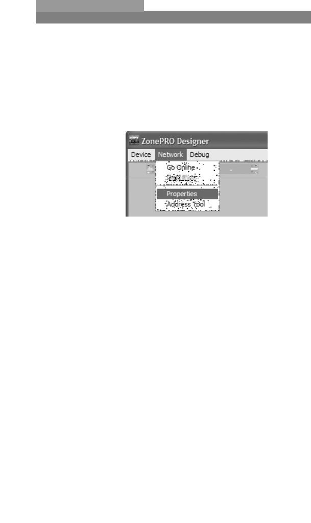
2.3.2 Network Menu
The Network Menu provides access to network parameters. If the computer cannot connect to the ZonePro device you can select Properties from the Network Menu and check the COM port assignment to make sure that you are connecting to the correct COM port. The Network Menu also provides an Address Tool that can be used to discover other devices on the network and resolve any address conflicts that may arise between units.
Note: Nodes
Any device that is on the network is considered a node and must be given a node address; this is just usually a simple one or two digit number. Once you place the first device on the network the GUI will assist you as you add further devices by adding 1 to the previous node address as you add devices. For example, if the first device on the network is node address 1, the second will be 2, and the third 3, unless you specifically change the node address with the Network Address Tool. If the computer cannot connect to the ZonePRO device, check the COM port assignment under Network Properties in the Venue View, and make sure that you are connecting to the correct COM port.
Note: Setting up a basic Network
The enclosed crossover Ethernet cable is used to connect a computer directly to a ZonePRO 1260/1261 without a hub or a switch. If you are using a hub or a switch, you must provide your own cabling. Since this cable is a crossover cable, it can not be used to wire Zone Controllers or link to multiple ZonePRO units together using the Input Link Bus.
The factory default IP settings for the ZonePRO are as follows:
IP Address: |
169.254.2.2 |
Subnet Mask: |
255.255.0.0 |
Default Gateway: |
0.0.0.0 |
These default settings are used for a simplified configuration when using Microsoft Window's Automatic IP assignment. When Windows is configured to automatically obtain its IP settings it will fall back to a network configuration that is compatible with the ZonePRO 1260 / 1261 if the computer is on a network without a DHCP/BOOTP server. Using the enclosed crossover cable is an example of such a network and is the recommended method of configuring a new unit. Please keep in mind that it takes MS Windows 1-2 minutes after the cable is attached and the ZonePRO is powered on for it to have its network settings compatible with the ZonePRO. Because of this, do not start the ZonePRO Designer software for about 2 minutes after the cables have been attached. For more information on how to properly configure the network setting please refer to the appendix.
ZonePRO™ User Manual |
7 |
|
|

|
|
™ |
Section 2 |
Software Overview |
ZonePRO |
|
|
2. 4 - Unit View Functions
The Unit View provides access to the signal routing configuration, Zone Controller assignment, and processing parameters.
2.4.1 File Menu
The File Menu selection allows saving of the existing ZonePRO device file (.zpd) as well as recalling of other files. The device file provides a way to store off the entire ZonePRO unit to a computer, which includes the configuration, scenes, and schedule information. To save a ZonePRO device file, select File then Save from the Menu bar. Recalling a saved file can be done by selecting Open from the File Menu. Once all of your changes have been made, simply close the file with the Close selection.
2.4.2 Edit Menu
To edit a processing module, double click on that module. Adjust the module to taste; make sure that the module is engaged. This is usually indicated by the module ON button in the upper left corner of the parameter section. Although process editing is done in real-time, the changes can either be discarded or accepted by selecting the OK or CANCEL button. Parameters can be copied and pasted between like modules in the ZonePRO GUI. From the program screen either right click on the module and select Copy, or select Edit and Copy from the Menu Bar to Copy parameters. To paste, either right click and select Paste, or click on Edit Paste from the Menu bar. Selecting Time in the Edit Menu allows editing of the date and time in the ZonePRO device's real time clock
2.4.3 Scenes Menu
Scenes include parameter data and zone controller assignment. Multiple scenes can be saved and recalled by either clicking on the Scene tab of the Menu bar and selecting Store or Recall Scene, or by using the Store Scene and Recall Scene buttons at the bottom of the Unit view window.
8 |
ZonePRO™ User Manual |
|
|
 Loading...