


20 SERIES
E Q U A L I Z E R / L I M I T E R w i t h T Y P E I I I N R
Operation Manual
Mode d’emploi
Bedienungsanleitung
Modo de empleo

IMPORTANT SAFETY INFORMATION
C A U T I O N |
RISK OF ELECTRIC SHOCK |
DO NOT OPEN |
ATTENTION: RISQUE DE CHOC ELECTRIQUE - NE PAS OUVRIR |
WARNING: TO REDUCE THE RISK OF FIRE OR ELECTRIC
SHOCK DO NOT EXPOSE THIS EQUIPMENT TO RAIN OR MOISTURE
The symbols shown above are internationally accepted symbols that warn of potential hazards with electrical products. The lightning flash with arrowpoint in an equilateral triangle means that there are dangerous voltages present within the unit. The exclamation point in an equilateral triangle indicates that it is necessary for the user to refer to the owner’s manual.
These symbols warn that there are no user serviceable parts inside the unit. Do not open the unit. Do not attempt to service the unit yourself. Refer all servicing to qualified personnel. Opening the chassis for any reason will void the manufacturer’s warranty. Do not get the unit wet. If liquid is spilled on the unit, shut it off immediately and take it to a dealer for service. Disconnect the unit during storms to prevent damage.
Safety Instructions
Notice For Customers If Your Unit Is Equipped With A Power Cord.
WARNING: THIS APPLIANCE SHALL BE CONNECTED TO A MAINS SOCKET OUTLET WITH A PROTECTIVE EARTHING CONNECTION.
The cores in the mains lead are coloured in accordance with the following code:
GREEN and YELLOW - Earth BLUE - Neutral BROWN - Live
As colours of the cores in the mains lead of this appliance may not correspond with the coloured markings identifying the terminals in your plug, proceed as follows:
•The core which is coloured green and yellow must be connected to the terminal in the plug marked with the letter E, or with the earth symbol, or coloured green, or green and yellow.
•The core which is coloured blue must be connected to the terminal marked N or coloured black.
•The core which is coloured brown must be connected to the terminal marked L or coloured red.
This equipment may require the use of a different line cord, attachment plug, or both, depending on the available power source at installation. If the attachment plug needs to be changed, refer servicing to qualified service personnel who should refer to the table below. The green/yellow wire shall be connected directly to the units chassis.
CONDUCTOR |
WIRE COLOR |
|||
Normal |
Alt |
|||
|
|
|||
L |
LIVE |
BROWN |
BLACK |
|
N |
NEUTRAL |
BLUE |
WHITE |
|
E |
EARTH GND |
GREEN/ |
GREEN |
|
YEL |
||||
|
|
|
||
WARNING: If the ground is defeated, certain fault conditions in the unit or in the system to which it is connected can result in full line voltage between chassis and earth ground. Severe injury or death can then result if the chassis and earth ground are touched simultaneously.
WARNING FOR YOUR PROTECTION
READ THE FOLLOWING:
KEEP THESE INSTRUCTIONS HEED ALL WARNINGS
FOLLOW ALL INSTRUCTIONS
the apparatus shall not be exposed to dripping or splashing liquid and no object filled with liquid, such as vases, shall be placed on the apparatus.
CLEAN ONLY WITH A DRY CLOTH.
DO NOT BLOCK ANY OF THE VENTILATION OPENINGS. INSTALL IN ACCORDANCE WITH THE MANUFACTURER’S INSTRUCTIONS.
DO NOT INSTALL NEAR ANY HEAT SOURCES SUCH AS RADIATORS,
HEAT REGISTERS, STOVES, OR OTHER APPARATUS (INCLUDING AMPLI-
FIERS) THAT PRODUCE HEAT.
ONLY USE ATTACHMENTS/ACCESSORIES SPECIFIED BY THE MANUFACTURER.
UNPLUG THIS APPARATUS DURING LIGHTNING STORMS OR WHEN UNUSED FOR LONG PERIODS OF TIME.
Do not defeat the safety purpose of the polarized or grounding-type plug. A polarized plug has two blades with one wider than the other. A grounding type plug has two blades and a third grounding prong. The wide blade or third
prong are provided for your safety. If the provided plug does not fit your outlet, consult an electrician for replacement of the obsolete outlet.
Protect the power cord from being walked on or pinched particularly at plugs, convenience receptacles, and the point where they exit from the apparatus.
Use only with the cart stand, tripod bracket, or table specified by the manufacture, or sold with the apparatus. When a cart is used, use caution when moving the cart/apparatus combination to avoid injury from tip-over.
Refer all servicing to qualified service personnel. Servicing is required when the apparatus has been damaged in any way, such as power-supply cord or plug is damaged, liquid has been spilled or objects have fallen into the apparatus, the apparatus has been exposed to rain or moisture, does not operate normally, or has been dropped.
POWER ON/OFF SWITCH: If the equipment has a Power switch, the Power switch used in this piece of equipment DOES NOT break the connection from the mains.
MAINS DISCONNECT: The plug shall remain readily operable. For rack-mount or installation where plug is not accessible, an all-pole mains switch with a contact separation of at least 3 mm in each pole shall be incorporated into the electrical installation of the rack or building.
FOR UNITS EQUIPPED WITH EXTERNALLY ACCESSIBLE FUSE RECEPTACLE: Replace fuse with same type and rating only.
MULTIPLE-INPUT VOLTAGE:This equipment may require the use of a different line cord, attachment plug, or both, depending on the available power source at installation. Connect this equipment only to the power source indicated on the equipment rear panel.To reduce the risk of fire or electric shock, refer servicing to qualified service personnel or equivalent.
If connected to 240V supply, a suitable CSA/UL certified power cord shall be used for this supply.
This Equipment Is Intended For Rack Mount Use Only.

IMPORTANT SAFETY INFORMATION
U.K. MAINS PLUG WARNING
A molded mains plug that has been cut off from the cord is unsafe. Discard the mains plug at a suitable disposal facility. NEVER
UNDER ANY CIRCUMSTANCES SHOULDYOU INSERT A DAMAGED OR CUT MAINS PLUG INTO A 13 AMP POWER SOCKET. Do not use the mains plug without the fuse cover in place. Replacement fuse covers can be obtained from your local retailer. Replacement fuses are 13 amps and MUST be ASTA approved to BS1362.
ELECTROMAGNETIC COMPATIBILITY
This unit conforms to the Product Specifications noted on the Declaration of Conformity. Operation is subject to the following two conditions:
•this device may not cause harmful interference, and
•this device must accept any interference received, including interference that may cause undesired operation.
Operation of this unit within significant electromagnetic fields should be avoided.
• use only shielded interconnecting cables.
Warranty
This warranty is valid only for the original purchaser and only in the United States.
1.The warranty registration card that accompanies this product must be mailed within 30 days after purchase date to validate this warranty. You can also register online at www.dbxpro.com. Proof-of-purchase is considered to be the responsibility of the consumer. A copy of the original purchase receipt must be provided for any warranty service.
2.dbx warrants this product, when bought and used solely within the U.S., to be free from defects in materials and workmanship under normal use and service.
3.dbx liability under this warranty is limited to repairing or, at our discretion, replacing defective materials that show evidence of defect, provided the product is returned to dbx WITH RETURN AUTHORIZATION from the factory, where all parts and labor will be covered up to a period of two years. A Return Authorization number must first be obtained from dbx. The company shall not be liable for any consequential damage as a result of the product’s use in any circuit or assembly.
4.dbx reserves the right to make changes in design or make additions to or improvements upon this product without incurring any obligation to install the same additions or improvements on products previously manufactured.
5.The foregoing is in lieu of all other warranties, expressed or implied, and dbx neither assumes nor authorizes any person to assume on its behalf any obligation or liability in connection with the sale of this product. In no event shall dbx or its dealers be liable for special or consequential damages or from any delay in the performance of this warranty due to causes beyond their control.
If you want to dispose this product, do not mix it with general household waste. There is a separate collection system for used electronic products in accordance with legislation that requires proper treatment, recovery and recycling.
Private household in the 25 member states of the EU, in Switzerland and Norway may return their used electronic products free of charge to designated collection facilities or to a retailer (if you purchase a similar new one).
For Countries not mentioned above, please contact your local authorities for a correct method of disposal.
By doing so you will ensure that your disposed product undergoes the necessary treatment, recovery and recycling and thus prevent potential negative effects on the environment and human health.
LITHIUM BATTERY
WARNING
CAUTION!
This product may contain a lithium battery.There is danger of explosion if the battery is incorrectly replaced. Replace only with an Eveready CR 2032 or equivalent. Make sure the battery is installed with the correct polarity. Discard used batteries according to manufacturer’s instructions.
ADVARSEL!
Lithiumbatteri - Eksplosjonsfare.Ved utskifting benyttes kun batteri som anbefalt av apparatfabrikanten. Brukt batteri returneres apparatleverandøren.
ADVARSEL!
Lithiumbatteri - Eksplosionsfare ved fejlagtig håndtering. Udskiftning må kun ske med batteri av samme fabrikat og type. Levér det brugte batteri tilbage til leverandøren.
VAROITUS!
Paristo voi räjähtää, jos se on virheellisesti asennettu.Vaihda paristo ainoastaan laitevalmistajan suosittelemaan tyyppin. Hävitä käytetty paristo valmistajan ohjeiden mukaisesti.
VARNING!
Explosionsfara vid felaktigt batteribyte.Använd samma batterityp eller en ekvivalent typ som rekommenderas av apparattillverkaren. Kassera använt batteri enligt fabrikantens instruktion.
DECLARATION OF CONFORMITY
Manufacturer’s Name: |
dbx Professional Products |
Manufacturer’s Address: |
8760 S. Sandy Parkway |
|
Sandy, Utah 84070, USA |
declares that the product: |
|
Product name: |
dbx 2031, dbx2215 and dbx2231 |
Note: Product name may be suffixed by the letters-EU. |
|
Product option: |
None |
conforms to the following Product Specifications: |
|
Safety: |
IEC 60065 -01+Amd 1 |
EMC: |
EN 55022:2006 (N/A; Analog Product) |
|
IEC61000-4-2 |
|
IEC61000-4-3 |
|
IEC61000-4-4 |
|
IEC61000-4-5 |
|
IEC61000-4-6 |
|
IEC61000-4-8 |
|
IEC61000-4-11 |
Supplementary Information:
The product herewith complies with the requirements of the:
Low Voltage Directive 2006/95/EC
EMC Directive 2004/108/EC.
RoHS Directive 2002/95/EC
WEEE Directive 2002/96/EC
With regard to Directive 2005/32/EC and EC Regulation 1275/2008 of 17 December 2008, this product is designed, produced, and classified as Professional Audio Equipment and thus is exempt from this Directive.
Roger Johnsen
Director, Engineering
Signal Processing
8760 S. Sandy Parkway
Sandy, Utah 84070, USA
Date: November 19, 2010
European Contact: Your local dbx Sales and Service Office or
Harman Music Group
8760 South Sandy Parkway
Sandy, Utah 84070 USA
Ph: (801) 566-8800
Fax: (801) 568-7583

20 SERIES GRAPHIC EQUALIZERS
OPERATION MANUAL
Manual Contents
English |
. . . . . . . . . . . . . . . . . . . . . . . . . . . . . . . . . . . . . . . . . . . . . . . . . . . . . |
2 |
Français |
. . . . . . . . . . . . . . . . . . . . . . . . . . . . . . . . . . . . . . . . . . . . . . . . . . . . . |
7 |
Deutsch |
. . . . . . . . . . . . . . . . . . . . . . . . . . . . . . . . . . . . . . . . . . . . . . . . . . . . . |
15 |
Español |
. . . . . . . . . . . . . . . . . . . . . . . . . . . . . . . . . . . . . . . . . . . . . . . . . . . . . |
23 |
English Contents
Introduction . . . . . . . . . . . . . . . . . . . . . . . . . . . . . . . . . . . . . . . . . . . . . . . . . . 2 Inspection . . . . . . . . . . . . . . . . . . . . . . . . . . . . . . . . . . . . . . . . . . . . . . . . . . . . 2 Operating Controls . . . . . . . . . . . . . . . . . . . . . . . . . . . . . . . . . . . . . . . . . . . 2 Connecting the EQ to your System . . . . . . . . . . . . . . . . . . . . . . . . . . . . . . 4 Rear Panel Descriptions . . . . . . . . . . . . . . . . . . . . . . . . . . . . . . . . . . . . . . . . 4 Installation Considerations . . . . . . . . . . . . . . . . . . . . . . . . . . . . . . . . . . . . 5 Operation and Applications Notes . . . . . . . . . . . . . . . . . . . . . . . . . . . . . . . 6 Technical Support / Factory Service . . . . . . . . . . . . . . . . . . . . . . . . . . . . . 6 Specifications . . . . . . . . . . . . . . . . . . . . . . . . . . . . . . . . . . . . . . . . . . . . . . . . . 32 Block Diagram . . . . . . . . . . . . . . . . . . . . . . . . . . . . . . . . . . . . . . . . . . . . . . . . 33
1
OPERATION MANUAL
Introduction
Congratulations on your purchase of a dbx graphic equalizer. All dbx graphic equalizers are high performance multifunctional units designed to deliver all the flexibility and power that professional users demand. We recommend that you take a moment to read through this operation manual. It provides information that will assist you from system setup to EQ applications. The 20 Series Equalizers include the following features:
•Revolutionary dbx TYPE III™ Noise Reduction capable of restoring up to 20dB S/N ratio
•Proprietary patent-pending PeakPlus™ Limiter for system protection
•Switchable range between ±6dB and ±15dB
•Balanced inputs and outputs
•XLR, Barrier Strip, and 1/4” TRS connectors
•-12dB/+12dB input gain range
•18dB/octave 40Hz Bessel Low-Cut filter
•Chassis/signal ground lift capability
•Internal power supply transformer
•Power-off hard-wire relay bypass with 2-second power-up delay
Inspection
Verify that the equalizer’s package contains the following:
•Equalizer unit matching serial number marked on package
•AC power cord
•Operation Manual
•Registration Card
•Four rack mount screws and washers
If any of these items are missing please contact dbx customer service at the number provided on the back cover of this manual.
Operating Controls
Front Panels
2031 - single channel 31 band graphic equalizer
|
|
|
|
|
|
|
|
|
20 |
25 |
31.5 |
40 |
50 |
63 |
80 |
100 |
125 |
160 |
200 |
250 |
315 |
400 |
500 |
630 |
800 |
1k |
1.25k |
1.6k |
2k |
2.5k |
3.15k |
4k |
5k |
6.3k |
8k |
10k |
12.5k |
16k |
20k |
|
-10 |
0 |
+10 |
+18 |
10 |
6 |
3 |
1 |
+6 |
|
|
|
|
|
|
|
|
|
|
|
|
|
|
|
|
|
|
|
|
|
|
|
|
|
|
|
|
|
+15 |
|
|
OUTPUT |
|
|
GAIN |
|
|
|
|
|
|
|
|
|
|
|
|
|
|
|
|
|
|
|
|
|
|
|
|
|
|
|
|
|
|
|
|
||
|
LEVEL (dBu) |
|
REDUCTION (dB) |
|
|
|
|
|
|
|
|
|
|
|
|
|
|
|
|
|
|
|
|
|
|
|
|
|
|
|
|
|
|
|
|||||
|
CLIP |
|
|
|
|
|
|
|
+/-15 |
|
|
|
|
|
|
|
|
|
|
|
|
|
|
|
|
|
|
|
|
|
|
|
|
|
|
|
|
|
|
|
|
|
0 |
|
+10 |
|
|
+15 |
|
|
|
|
|
|
|
|
|
|
|
|
|
|
|
|
|
|
|
|
|
|
|
|
|
|
|
|
|
|
|
|
|
|
|
|
|
|
+/-6 0 |
|
|
|
|
|
|
|
|
|
|
|
|
|
|
|
|
|
|
|
|
|
|
|
|
|
|
|
|
|
0 |
||
|
|
|
|
|
|
|
|
|
|
|
|
|
|
|
|
|
|
|
|
|
|
|
|
|
|
|
|
|
|
|
|
|
|
|
|
|
|
||
|
|
|
|
+5 |
|
|
|
|
+20 |
|
|
|
|
|
|
|
|
|
|
|
|
|
|
|
|
|
|
|
|
|
|
|
|
|
|
|
|
|
|
TYPE III |
-12 |
|
dB +12 |
0 |
|
dBu |
OFF |
|
|
|
|
|
|
|
|
|
|
|
|
|
|
|
|
|
|
|
|
|
|
|
|
|
|
|
|
|
|
|
|
EQ |
INPUT |
LOW |
PeakPlus |
RANGE |
|
|
|
|
|
|
|
|
|
|
|
|
|
|
|
|
|
|
|
|
|
|
|
|
|
|
|
|
|
|
|||||
NR |
BYPASS |
GAIN |
CUT |
THRESHOLD |
-6 |
|
|
|
|
|
|
|
|
|
|
|
|
|
|
|
|
|
|
|
|
|
|
|
|
|
|
|
|
|
-15 |
||||
2031
Equalizer/Limiter with TYPE III NR
2231 - dual channel 31 band graphic equalizer
|
-10 |
0 |
+10 |
+18 |
10 |
6 |
3 |
1 |
|
+6 |
|
|
|
|
|
|
|
|
|
|
|
|
|
|
|
|
|
|
|
|
|
|
|
|
|
|
|
|
|
|
+15 |
|
|
|
OUTPUT |
|
|
GAIN |
|
|
|
|
|
|
|
|
|
|
|
|
|
|
|
|
|
|
|
|
|
|
|
|
|
|
|
|
|
|
|
|
|
|
|
||
|
LEVEL (dBu) |
REDUCTION (dB) |
|
|
|
|
|
|
|
|
|
|
|
|
|
|
|
|
|
|
|
|
|
|
|
|
|
|
|
|
|
|
|
|
|
|
||||||
|
CLIP |
|
|
|
|
|
|
|
+/-15 |
|
|
|
|
|
|
|
|
|
|
|
|
|
|
|
|
|
|
|
|
|
|
|
|
|
|
|
|
|
|
|
|
|
|
|
|
0 |
|
+10 |
|
|
+15 |
|
|
|
|
|
|
|
|
|
|
|
|
|
|
|
|
|
|
|
|
|
|
|
|
|
|
|
|
|
|
|
|
|
|
|
|
|
|
|
|
|
|
|
+/-6 |
0 |
|
|
|
|
|
|
|
|
|
|
|
|
|
|
|
|
|
|
|
|
|
|
|
|
|
|
|
|
|
|
0 |
|
|
|
|
|
+5 |
|
|
|
|
+20 |
|
|
|
|
|
|
|
|
|
|
|
|
|
|
|
|
|
|
|
|
|
|
|
|
|
|
|
|
|
|
|
|
|
TYPE III |
-12 |
|
dB |
+12 |
0 |
|
dBu |
OFF |
|
|
|
|
|
|
|
|
|
|
|
|
|
|
|
|
|
|
|
|
|
|
|
|
|
|
|
|
|
|
|
|
|
|
EQ |
INPUT |
LOW |
PeakPlus |
RANGE |
|
|
|
|
|
|
|
|
|
|
|
|
|
|
|
|
|
|
|
|
|
|
|
|
|
|
|
|
|
|
|
|
||||||
NR |
BYPASS |
GAIN |
CUT |
THRESHOLD |
|
-6 |
|
|
|
|
|
|
|
|
|
|
|
|
|
|
|
|
|
|
|
|
|
|
|
|
|
|
|
|
|
|
-15 |
2231 |
||||
|
|
|
|
|
|
|
|
|
|
20 |
25 |
31.5 |
40 |
50 |
63 |
80 |
100 |
125 |
160 |
200 |
250 |
315 |
400 |
500 |
630 |
800 |
1k |
1.25k |
1.6k |
2k |
2.5k |
3.15k |
4k |
5k |
6.3k |
8k |
10k |
12.5k |
16k |
20k |
|
|
|
|
|
|
|
|
|
|
|
|
|
|
|
|
|
|
|
|
|
|
|
|
|
|
|
|
|
|
|
|
|
|
|
|
|
|
|
|
|
|
|
|
Equalizer/Limiter |
|
-10 |
0 |
+10 |
+18 |
10 |
6 |
3 |
1 |
|
+6 |
|
|
|
|
|
|
|
|
|
|
|
|
|
|
|
|
|
|
|
|
|
|
|
|
|
|
|
|
|
|
+15 |
with TYPE III NR |
|
|
|
|
|
|
|
|
|
|
|
|
|
|
|
|
|
|
|
|
|
|
|
|
|
|
|
|
|
|
|
|
|
|
|
|
|
|
|
|
|
|
|
|
|
OUTPUT |
|
|
GAIN |
|
|
|
|
|
|
|
|
|
|
|
|
|
|
|
|
|
|
|
|
|
|
|
|
|
|
|
|
|
|
|
|
|
|
|
||
|
LEVEL (dBu) |
REDUCTION (dB) |
|
|
|
|
|
|
|
|
|
|
|
|
|
|
|
|
|
|
|
|
|
|
|
|
|
|
|
|
|
|
|
|
|
|
||||||
|
CLIP |
|
|
|
|
|
|
|
+/-15 |
|
|
|
|
|
|
|
|
|
|
|
|
|
|
|
|
|
|
|
|
|
|
|
|
|
|
|
|
|
|
|
|
|
|
|
|
0 |
|
+10 |
|
|
+15 |
|
|
|
|
|
|
|
|
|
|
|
|
|
|
|
|
|
|
|
|
|
|
|
|
|
|
|
|
|
|
|
|
|
|
|
|
|
|
|
|
|
+/-6 |
0 |
|
|
|
|
|
|
|
|
|
|
|
|
|
|
|
|
|
|
|
|
|
|
|
|
|
|
|
|
|
|
0 |
|
||
|
|
|
|
|
|
|
|
|
|
|
|
|
|
|
|
|
|
|
|
|
|
|
|
|
|
|
|
|
|
|
|
|
|
|
|
|
|
|
|
|||
|
|
|
|
+5 |
|
|
|
|
+20 |
|
|
|
|
|
|
|
|
|
|
|
|
|
|
|
|
|
|
|
|
|
|
|
|
|
|
|
|
|
|
|
|
|
TYPE III |
-12 |
|
dB |
+12 |
0 |
|
dBu |
OFF |
|
|
|
|
|
|
|
|
|
|
|
|
|
|
|
|
|
|
|
|
|
|
|
|
|
|
|
|
|
|
|
|
|
|
EQ |
INPUT |
LOW |
PeakPlus |
RANGE |
|
|
|
|
|
|
|
|
|
|
|
|
|
|
|
|
|
|
|
|
|
|
|
|
|
|
|
|
|
|
|
|
||||||
NR |
BYPASS |
GAIN |
CUT |
THRESHOLD |
|
-6 |
|
|
|
|
|
|
|
|
|
|
|
|
|
|
|
|
|
|
|
|
|
|
|
|
|
|
|
|
|
|
-15 |
|
||||
2
20 SERIES GRAPHIC EQUALIZERS
OPERATION MANUAL
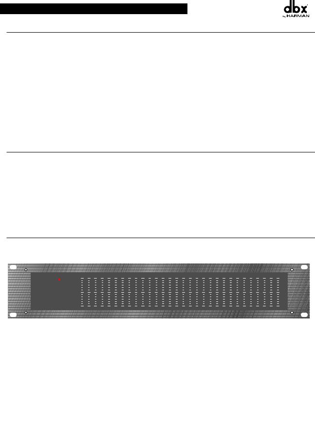
2215 - dual channel 15 band graphic equalizer
|
|
25 |
40 |
63 |
100 |
160 |
250 |
400 |
630 |
1k |
1.6k |
2.5k |
4k |
6.3k |
10k |
16k |
25 |
40 |
63 |
100 |
160 |
250 |
400 |
630 |
1k |
1.6k |
2.5k |
4k |
6.3k |
10k |
16k |
|
|
|
-10 |
0 |
+10 |
+18 |
10 |
6 |
3 |
1 |
+6 |
|
|
OUTPUT |
|
|
GAIN |
|
|
||
|
LEVEL (dBu) |
REDUCTION (dB) |
|
||||||
|
CLIP |
|
|
|
|
|
|
|
+/-15 |
|
|
|
0 |
|
+10 |
|
|
+15 |
|
|
|
|
|
|
|
|
|
|
+/-6 0 |
|
|
|
|
+5 |
|
|
|
|
+20 |
TYPE III |
-12 |
|
dB |
+12 |
0 |
|
dBu |
OFF |
|
EQ |
INPUT |
LOW |
PeakPlus |
RANGE |
|||||
NR |
BYPASS |
GAIN |
CUT |
THRESHOLD |
-6 |
||||
+15 |
|
-10 |
0 +10 |
+18 |
10 |
6 3 |
1 |
+6 |
|
|
|
OUTPUT |
|
|
GAIN |
|
|
|
|
LEVEL (dBu) |
|
REDUCTION (dB) |
|
|||
|
|
CLIP |
|
|
|
|
|
+/-15 |
|
|
|
0 |
|
+10 |
|
+15 |
|
0 |
|
|
|
|
|
|
|
+/-6 0 |
|
|
|
|
+5 |
|
|
|
+20 |
|
TYPE III |
-12 |
dB +12 |
0 |
dBu |
OFF |
|
|
|
EQ |
INPUT |
LOW |
PeakPlus |
RANGE |
|||
-15 |
NR |
BYPASS |
GAIN |
CUT |
THRESHOLD |
-6 |
||
+15


 0 2215
Equalizer/Limiter with TYPE III NR
-15
Input Gain Control: This control sets the signal level to the equalizer. It is capable of -12dB to +12dB of gain. Its effect is apparent by viewing the OUTPUT LEVEL BAR GRAPH.
EQ Bypass: This switch removes the graphic equalizer section from the signal path. (See Block diagram on Page 32.) The BYPASS switch does not, however, affect the INPUT GAIN, or LOW CUT filters.
EQ Bypass LED: This red LED lights when the EQ is in bypass mode. Note that bypass mode only effects the graphic equalizer section of the 20 Series EQs. The input gain and and low cut controls remain unaffected when the EQ is bypassed.
Boost/Cut Range Selection Switch and LEDs: This switch selects which of the two boost/cut ranges the equalizer will use, either ±6dB or ±15dB. The red LED lights when the ±15dB range is selected, and the yellow LED lights when the ±6dB range is selected. Note that the BOOST/CUT switch is slightly recessed. This is to prevent acciden- tal activation of the switch, possibly causing damage to other sound system components.
Output Level Bar Graph: These four LEDs indicate output level of the equalizer. The red LED is 3dB below clip- ping and is marked as +18dBu. It monitors the level at the output of the equalizer after all other processing, includ- ing the limiter.
Clip LED: This LED lights whenever any internal signal level reaches 3dB below clipping which may occur when any of the following happen: 1) the input signal is “hotter” than +22dBu, 2) excessive gain is applied by the input gain control, or 3) excessive boost is applied using the frequency sliders.
Gain Reduction Meter: These four LEDs indicate the amount of gain reduction being induced by the setting of the PeakPlus™ limiter threshold control as the signal level from the graphic EQ section exceeds this limiter threshold setting.
PeakPlus™ Limiter Threshold Control: This control engages the PeakPlus™ limiter. It sets the threshold level at which ∞:1 gain reduction will begin to occur. Its design is borrowed from the patent-pending PeakStopPlus™ Limiter found on the popular dbx 1066 and 1046 compressor/limiters. It is capable of a range of 0dBu through “off” (+24dBu). When the threshold control is set to “off”, the limiter is effectively disabled, and no gain reduc- tion will occur.
dbx Type III™ Noise Reduction Switch: The switch engages the dbx Type III™ Noise Reduction circuit within the EQ.
dbx Type III™ Noise Reduction LED: The yellow LED lights when the dbx Type III™ Noise Reduction circuit is activated via the Noise Reduction Switch.
Frequency Band Slider Controls: Each one of these slider potentiometers will boost or cut at its noted frequency by ±6dB or ±15dB, depending upon the position of the BOOST/CUT RANGE switch. When all the sliders are in the center detented position the output of the equalizer is flat. The frequency band centers of the 2031 and the 2231 are marked at 1/3rd of an octave intervals on ISO standard spacings, while the frequency band centers of the 2215 are marked at 2/3rds of an octave intervals on ISO standard spacings.
Low Cut Enable Switch: The LOW-CUT switch inserts or removes the 18dB/octave 40Hz Bessel low-cut filter from the signal path. When the LOW-CUT switch is pushed in, the LOW-CUT filter is IN the audio path.
3

OPERATION MANUAL
Connecting The EQToYour System
The 20 Series Equalizers have balanced inputs and outputs that can be used with any balanced or unbalanced line-
level device. For more specific information about cabling possibilities, please refer to the section entitled
Installation Considerations, Page 5.
To connect the equalizer to your sound system refer to the following steps:
•Turn off all equipment before making connections.
•Mount equalizer in a standard-width rack.
Install the EQs in a rack with the rack screws provided. It can be mounted above or below anything that does not generate excessive heat. Ambient temperatures should not exceed 113° F (45°C) when equipment is in use. Although the unit’s chassis is shielded against radio frequency and electromagnetic interference, extremely high fields of RF and EMI should be avoided.
•Make audio connections via XLR, barrier strip, or 1/4” TRS jacks (according to application needs)
All three types of connectors for the inputs and outputs can be used for balanced or unbalanced connections.
The use of more than one connector at a time for the inputs could unbalance balanced lines, cause phase cancel- lation, short a conductor to ground, or cause damage to other equipment connected to the equalizer. More than one output may be used simultaneously as long as the combined parallel load is greater than 600ΩΩ.
•Select the operating range with the boost/Cut range selection switch
Note: Be sure to reduce audio levels at the power amplifiers when changing the setting of this switch as it may generate an audible transient.
• apply power to the equalizer
Connect the AC power cord to the AC power receptacle on the back of the equalizer. Route the AC power cord to a convenient power outlet away from audio lines. The unit may be turned on and off from the rear panel power switch or a master equipment power switch. Since the 20 Series Equalizers consume a relatively small amount of power, the units may be left on continuously.
Rear Panel Descriptions
Rear Panels
2031 - single channel 31 band graphic equalizer
POWER
15 WATTS
100V 50/60Hz
120V 60Hz
CAUTION: TO REDUCE THE RISK OF FIRE REPLACE ONLY WITH SAME TYPE FUSE.
ATTENTION: UTILISER UN FUSIBLE DE RECHANGE DE MEME TYPE.
PROFESSIONAL PRODUCTS A HARMAN INTERNATIONAL COMPANY
SALT LAKE CITY, UTAH MADE IN USA
MODEL 2031 EQUALIZER/LIMITER WITH TYPE III NOISE REDUCTION
|
|
CONNECTOR POLARITY |
|
|
|
|
|
PHONE: |
XLR: |
|
|
|
|
TIP |
PIN 1 |
|
|
|
|
RING |
PIN 2 |
|
|
|
|
SLEEVE |
PIN 3 |
|
|
OUTPUT |
|
|
|
|
INPUT |
OUTPUT |
OUTPUT |
INPUT |
INPUT |
||
|
+ |
- |
- |
+ |
|
2231 - dual channel 31 band graphic equalizer
POWER
|
|
|
|
CAUTION: TO REDUCE |
|
|
|
|
|
THE RISK OF FIRE REPLACE |
RISK OF ELECTRIC SHOCK |
|
|
|
|
ONLY WITH SAME TYPE FUSE. |
DO NOT OPEN |
|
|
|
|
ATTENTION: UTILISER |
ATTENTION: RISQUE DE CHOC ELECTRIQUE - NE PAS OUVRIR |
|
|
|
|
UN FUSIBLE DE RECHANGE DE |
WARNING: TO REDUCE THE RISK OF FIRE OR ELECTRIC |
|
|
|
|
MEME TYPE. |
|
|
|
|
|
|
SHOCK DO NOT EXPOSE THIS EQUIPMENT TO RAIN OR MOISTURE |
|
28 WATTS |
|
|
||
|
|
|
|
PROFESSIONAL PRODUCTS |
|
|
|
|
|
A HARMAN INTERNATIONAL |
|
|
|
|
|
COMPANY |
|
|
|
|
|
SALT LAKE CITY, UTAH |
MANUFACTURED UNDER ONE OR MORE OF THE FOLLOWING |
|
|
|
|
MADE IN USA |
U.S. PATENTS: 4,234,804 4,316,107 4,329,598 4,331,931 4,377,792 |
|
|
|
|
MODEL 2231 |
|
|
|
|
|
EQUALIZER/LIMITER WITH |
4,403,199 4,409,500 4,425,551 4,434,380 4,454,433 4,471,324 |
100V |
50/60Hz |
TYPE III NOISE REDUCTION |
4,473,793 OTHER PATENTS PENDING |
||
120V |
60Hz |
|
|
||
OUTPUT |
|
|
|
|
INPUT |
OUTPUT |
OUTPUT |
INPUT |
INPUT |
||
|
+ |
- |
- |
+ |
|
|
|
CONNECTOR POLARITY |
|
|
|
|
|
PHONE: |
XLR: |
|
|
|
|
TIP |
PIN 1 |
|
|
|
|
RING |
PIN 2 |
|
|
|
|
SLEEVE |
PIN 3 |
|
|
OUTPUT |
|
|
|
|
INPUT |
OUTPUT |
OUTPUT |
INPUT |
INPUT |
||
|
+ |
- |
- |
+ |
|
4

20 SERIES GRAPHIC EQUALIZERS
OPERATION MANUAL
2215 - dual channel 15 band graphic equalizer
|
|
|
|
CAUTION: TO REDUCE |
|
|
POWER |
THE RISK OF FIRE REPLACE |
RISK OF ELECTRIC SHOCK |
||
|
ONLY WITH SAME TYPE FUSE. |
||||
|
|
|
|
DO NOT OPEN |
|
|
|
|
|
ATTENTION: UTILISER |
ATTENTION: RISQUE DE CHOC ELECTRIQUE - NE PAS OUVRIR |
|
|
|
|
UN FUSIBLE DE RECHANGE DE |
WARNING: TO REDUCE THE RISK OF FIRE OR ELECTRIC |
|
|
|
|
MEME TYPE. |
|
|
|
|
|
|
SHOCK DO NOT EXPOSE THIS EQUIPMENT TO RAIN OR MOISTURE |
|
28 WATTS |
|
|
||
|
|
|
|
PROFESSIONAL PRODUCTS |
|
|
|
|
|
|
|
|
|
|
|
A HARMAN INTERNATIONAL |
|
|
|
|
|
COMPANY |
|
|
|
|
|
SALT LAKE CITY, UTAH |
MANUFACTURED UNDER ONE OR MORE OF THE FOLLOWING |
|
|
|
|
MADE IN USA |
|
|
|
|
|
U.S. PATENTS: 4,234,804 4,316,107 4,329,598 4,331,931 4,403,199 |
|
|
|
|
|
MODEL 2215 |
|
|
|
|
|
EQUALIZER/LIMITER WITH |
4,409,500 4,425,551 4,434,380 4,454,433 4,471,324 4,473,793 |
100V |
50/60Hz |
TYPE III NOISE REDUCTION |
OTHER PATENTS PENDING |
||
120V |
60Hz |
|
|
||
CONNECTOR POLARITY
PHONE: |
XLR: |
TIP |
PIN 1 |
RING |
PIN 2 |
SLEEVE |
PIN 3 |
OUTPUT |
|
|
INPUT |
OUTPUT |
OUTPUT |
INPUT |
INPUT |
+ |
- |
- |
+ |
OUTPUT |
|
|
INPUT |
OUTPUT |
OUTPUT |
INPUT |
INPUT |
+ |
- |
- |
+ |
Power Cord Receptacle: Connects AC power to the equalizer.
Power Switch: Switches the power on and off. Always make audio connections with the power switch in the off position.
Input Connectors: Three types of input connectors are provided for input connections: female locking XLR type connectors, 1/4” tip-ring-sleeve phone jack connectors, and a barrier strip. The maximum input level that the equal- izer can accept is +22dBu (ref: 0.775Vrms).
Output Connectors: Three types of output connectors are provided for output connections: male XLR type con- nectors, 1/4” tip-ring-sleeve phone jack connectors and a barrier strip.
Chassis Ground Lift Strap: By removing the jumper connecting the two screws on the barrier strip, the chassis ground is separated from the circuit ground of the equalizer. This is sometimes necessary to prevent “ground loops” in a sound system. When lifting the ground strap, you must make a connection from the circuit ground ( ) terminal to some other ground point in your audio system in order for the equalizer to function properly.
WiringWIRINGConnectionsCONNECTIONS WithITH GROUNDGround
|
|
Without Jumper in Place |
|
With Jumper in Place |
|
||||
|
|
circuit |
chassis |
|
|
circuit |
chassis |
|
|
|
|
ground |
ground |
|
|
ground |
ground |
|
|
|
+ |
|
|
+ |
+ |
|
|
+ |
|
|
|
|
|
|
|
|
|
jumper |
|
to system |
|
|
|
|
|
|
|
|
|
ground |
+ |
|
|
|
+ |
|
|
|
|
|
|
|
+ |
|
|
+ |
|||
|
|
|
|
|
|
|
|||
Output |
optional |
Input |
Output |
optional |
Input |
||||
Cable |
Cable |
Cable |
Cable |
||||||
|
|
|
|
||||||
Installation Considerations
Hookups and Cabling: The 20 Series Equalizers are designed for nominal +4dBu levels. The equalizers can be used with either balanced or unbalanced sources, and the outputs can be used with either balanced or unbalanced loads, provided the proper cabling is used.
A balanced line is defined as two-conductor shielded cable with the two center conductors carrying the same signal but of opposite polarity when referenced to ground. An unbalanced line is generally a single-conductor shielded cable with the center conductor carrying the signal and the shield at ground potential.
Input Cable Configurations: The equalizer has an input impedance of 40kΩ balanced and 20kΩ unbalanced. This makes the 20 Series Equalizers’ audio inputs suitable for use with virtually any low source impedance (under 2kΩ).
Output Cable Configurations: The equalizer’s output is capable of driving a 600Ω load to +18dBu. For maximum hum rejection with a balanced source, avoid common grounding at the equalizer’s inputs and outputs. Most bal- anced (3-conductor) cables have the shield connected at both ends. This can result in ground loops which cause hum. If hum persists try disconnecting the shield on one or more of the cables in the system, preferably at the input of a device, not at the output.
5

OPERATION MANUAL
Operation and Application Notes
The dbx 20 Series Graphic Equalizers are useful audio signal processing tools in situations where precise frequency control is required across the audible frequency spectrum.
When used with an audio spectrum analyzer the EQs can tune any acoustical environment -- from the studio to the concert hall -- to stop ringing, increase clarity, and flatten the overall frequency response of the environment. A real-time spectrum analyzer or other types of audio environment analyzers are very useful in determining the amount of equalization needed.
Insert the graphic equalizer between the signal source (usually a mixer) and the power amplifiers (or the crossover if there is one). Adjust the level and equalization as required to yield the desired system response. The long throw fad- ers of the EQs allow very precise settings of the equalization for accurate equalization curves.
For optimum signal-to-noise response, the gain structure of the sound system must be properly set up. Each compo- nent of the sound system should be set at its nominal operating level, starting with the first element in the system, usually a mixing console. Each element should be run at its nominal operating level in order to take advantage of the maximum signal-to-noise properties of that element. Loudspeaker amplifiers, as the last element in the chain, should be set only as loud as necessary, in order to avoid inducing unnecessary noise into the system.
All active equalizers, by nature of design, add noise when boosting or cutting that can easily degrade the otherwise acceptable signal-to-noise ratio of a sound system. Drastic equalization can result in a loss of 20dB or more signal- to-noise. dbx Type III™ Noise Reduction was engineered specifically for applications such as this. It provides up to 20dB of noise reduction, thus restoring the dynamic range necessary for even the most demanding professional sound systems. The combination of proper wiring, proper gain structure and TYPE III™ Noise Reduction should render your sound system virtually noise free.
Technical Support / Factory Service
The dbx 20 Series EQs are all solid-state products with components chosen for high performance and excellent reli- ability. Each unit has been tested and burned-in at the factory. No adjustment of any type should be required throughout the life of the unit.
If circumstances arise which necessitate repair, we recommend that your EQ be returned to the factory. This can only be done by receiving a RETURN AUTHORIZATION number from dbx customer service.
If you require technical support contact Customer Service. Be prepared to accurately describe the problem. Know the serial number of your unit (printed on a sticker attached to the chassis of the unit).
Contact information is printed on the back cover of this manual.
6
20 SERIES GRAPHIC EQUALIZERS
OPERATION MANUAL
FRANÇAIS
7

C A U T I O N |
RISK OF ELECTRIC SHOCK |
DO NOT OPEN |
ATTENTION: RISQUE DE CHOC ELECTRIQUE - NE PAS OUVRIR |
WARNING: TO REDUCE THE RISK OF FIRE OR ELECTRIC SHOCK DO NOT EXPOSE THIS EQUIPMENT TO RAIN OR MOISTURE
Les symboles montrés ci-dessus sont internationaux et concernent les appareils électriques. Le symbole de gauche vous avertit de la présence d’une tension dangereuse, suffisante pour provoquer un choc électrique. Le symbole de droite vous avertit que les instructions de fonctionnement sont importantes. Prenez soin de lire le manuel.
Ces symboles indiquent qu’aucune pièce n’est accessible à l’intérieur de l’appareil. Ne pas ouvrir l’appareil. Ne pas essayer de dépanner. S’adresser à un technicien qualifié. L’ouverture de l’appareil sans raison annulera la garantie constructeur. Ne pas mouiller l’appareil. Si un liquide est renversé dessus, éteindre immédiatement l’appareil et le porter chez le distributeur pour dépannage. Débrancher l’appareil en cas d’orage pour éviter des dommages.
ATTENTION
POURVOTRE PROTECTION, LISEZ CE QUI SUIT :
EAU ET MOISISSURE : L’appareil ne doit pas être utilisé près d’une source d’eau (par exemple près d’une baignoire, cuvette, évier, dans un sous-sol humide, ou près d’une piscine, etc.). Faire attention à ce qu’aucun objet ou liquide ne pénètre dans l’appareil par certaines ouvertures.
ALIMENTATION : Veiller à respecter la tension secteur correspondante.
MASSE ET POLARITE : Prendre soin de respecter la polarité et la mise à la masse. CORDON SECTEUR : Le cordon secteur doit être placé de manière à éviter d’être coincé par d’autres appareils et qu’on ne puisse pas marcher dessus, vérifier bien le cordon à son embase et à sa prise.
DEPANNAGE : Pour éviter le risque d’incendie et de choc électrique, l’utilisateur ne doit pas tenter de dépanner l’appareil en dehors des instructions indiquées dans le manuel d’utilisation. En cas de panne, s’adresser à un technicien qualifié.
POUR LES APPAREILS EQUIPES D’UN FUSIBLE ACCESSIBLE DE L’EXTERIEUR : Remplacer le fusible par un fusible de même type et de même valeur.
Instructions DE SECURITE
NOTE CONCERNANT LES APPAREILS MUNIS D’UN CORDON SECTEUR
ATTENTION : L’APPAREIL DOIT ETRE RELIE A LA TERRE
Les conducteurs du câble secteur sont identifiés comme suit :
Vert/Jaune |
Terre |
Bleu |
Neutre |
Brun |
Phase |
Si la couleur des conducteurs du câble secteur de cet appareil ne correspond pas à la couleur des conducteurs de la prise, procéder comme suit :
•Le conducteur vert/jaune doit être relié au fil vert ou vert/jaune ou marqué avec la lettre E, ou avec le symbole Terre.
•Le conducteur bleu doit être relié au fil noir ou marqué avec la lettre N.
•Le conducteur brun doit être relié au fil rouge ou marqué avec la lettre L.
CONDUCTEUR |
COULEUR |
|||
|
|
|||
Normal |
AUTRE |
|||
|
|
|||
L |
PHASE |
BRUN |
NOIR |
|
N |
NEUTRE |
BLEU |
BLANC |
|
|
|
|
|
|
E |
TERRE |
JAUNE/VERT |
VERT |
|
|
|
|
|
|
ATTENTION : si la mise à la terre est absente, certains problèmes peuvent apparaître dans l’appareil ou le système auquel il est connecté en cas de tension importante entre le châssis et la terre. De sérieux risques de blessures graves et même de mort existent en cas de contact simultané de la masse châssis et de la terre.
COMPATIBILITE ELECTROMAGNETIQUE
L’appareil est conforme aux normes indiquées sur la Déclaration de conformité.
•cet appareil ne provoquera pas de parasites nuisibles
•cet appareil supporte tout parasite, même un parasite qui pourrait causer un
dysfonctionnement.
L’utilisation de cet appareil dans un champ électromagnétique important doit être évitée.
DÉCLARATION DE CONFORMITÉ
Nom du fabricant: |
dbx Professional Products |
Adresse du fabricant: |
8760 S. Sandy Parkway |
|
Sandy, Utah 84070, USA |
Déclare que le produit: |
|
Nom du produit: |
dbx 2031, dbx2215 and dbx2231 |
Option du produit: |
Non communiquée |
est conforme aux caractéristiques suivantes : |
|
Sécurité: |
IEC 60065 -01+Amd 1 |
EMC: |
EN 55022:2006 (N/A; Analog Product) |
|
IEC61000-4-2 |
|
IEC61000-4-3 |
|
IEC61000-4-4 |
IEC61000-4-5
IEC61000-4-6
IEC61000-4-8
IEC61000-4-11
Informations supplémentaires:
Ce produit est conforme aux exigences de:
Low Voltage Directive 2006/95/EC
EMC Directive 2004/108/EC.
RoHS Directive 2002/95/EC
WEEE Directive 2002/96/EC
En ce qui concerne la Directive 2005/32/EC et Règlement de CE 1275/2008 du 17 décembre 2008, ce produit est conçu, est produit, et est classifié comme Equipement Audio Professionnel et est ainsi exempt de cette Directive.
Roger Johnsen
Director, Engineering
Signal Processing
8760 S. Sandy Parkway
Sandy, Utah 84070, USA
Date: November 19, 2010
Contact européen: Votre revendeur local dbx ou
Harman Music Group 8760 South Sandy Parkway Sandy, Utah
84070 USA
(801) 566-8800
(801) 568-7583
 Loading...