


® |
Complete Equalization & Loudspeaker Management System |
442 |
480 |
481 |
482 |
480R |
® |
User Manual |
IMPORTANT SAFETY INSTRUCTIONS
C A U T I O N |
RISK OF ELECTRIC SHOCK |
DO NOT OPEN |
ATTENTION: RISQUE DE CHOC ELECTRIQUE - NE PAS OUVRIR |
WARNING: TO REDUCE THE RISK OF FIRE OR ELECTRIC SHOCK DO NOT EXPOSE THIS EQUIPMENT TO RAIN OR MOISTURE
The symbols shown above are internationally accepted symbols that warn of potential hazards with electrical products. The lightning flash with arrowpoint in an equilateral triangle means that there are dangerous voltages present within the unit. The exclamation point in an equilateral triangle indicates that it is necessary for the user to refer to the owner’s manual.
These symbols warn that there are no user serviceable parts inside the unit. Do not open the unit. Do not attempt to service the unit yourself. Refer all servicing to qualified personnel. Opening the chassis for any reason will void the manufacturer’s warranty. Do not get the unit wet. If liquid is spilled on the unit, shut it off immediately and take it to a dealer for service. Disconnect the unit during storms to prevent damage.
SAFETY INSTRUCTIONS
NOTICE FOR CUSTOMERS IF YOUR UNIT IS EQUIPPED WITH A POWER CORD.
WARNING: THIS APPLIANCE MUST BE EARTHED.
CAUTION: EQUIPMENT IS NOT DISCONNECTED FROM MAINS WHEN SWITCH IS IN THE OFF POSITION
The cores in the mains lead are coloured in accordance with the following code:
GREEN and YELLOW - Earth |
BLUE - Neutral |
BROWN - Live |
As colours of the cores in the mains lead of this appliance may not correspond with the coloured markings identifying the terminals in your plug, proceed as follows:
•The core which is coloured green and yellow must be connected to the terminal in the plug marked with the letter E, or with the earth symbol, or coloured green, or green and yellow.
•The core which is coloured blue must be connected to the terminal marked N or coloured black.
•The core which is coloured brown must be connected to the terminal marked L or coloured red.
This equipment may require the use of a different line cord, attachment plug, or both, depending on the available power source at installation. If the attachment plug needs to be changed, refer servicing to qualified service personnel who should refer to the table below. The green/yellow wire shall be connected directly to the units chassis.
CONDUCTOR |
WIRE COLOR |
|||
|
|
|||
Normal |
Alt |
|||
|
|
|||
|
|
|
|
|
L |
LIVE |
BROWN |
BLACK |
|
|
|
|
|
|
N |
NEUTRAL |
BLUE |
WHITE |
|
|
|
|
|
|
E |
EARTH GND |
GREEN/YEL |
GREEN |
|
WARNING: If the ground is defeated, certain fault conditions in the unit or in the system to which it is connected can result in full line voltage between chassis and earth ground. Severe injury or death can then result if the chassis and earth ground are touched simultaneously.
WARNING FOR YOUR PROTECTION
PLEASE READ THE FOLLOWING:
KEEP THESE INSTRUCTIONS
HEED ALL WARNINGS
FOLLOW ALL INSTRUCTIONS
CLEAN ONLY WITH A DRY CLOTH.
DO NOT BLOCK ANY OF THE VENTILATION OPENINGS. INSTALL IN ACCORDANCE WITH THE MANUFACTURER’S INSTRUCTIONS.
DO NOT INSTALL NEAR ANY HEAT SOURCES SUCH AS RADIATORS, HEAT REGISTERS, STOVES, OR OTHER APPARATUS (INCLUDING AMPLIFIERS) THAT PRODUCE HEAT.
ONLY USE ATTACHMENTS/ACCESSORIES SPECIFIED BY THE MANUFACTURER.
UNPLUG THIS APPARATUS DURING LIGHTNING STORMS OR WHEN UNUSED FOR LONG PERIODS OF TIME.
GROUNDING PRONG: The wide blade or the third prong are provided for your safety. If the provided plug does not fit into your outlet, consult an electrician for replacement of the obsolete outlet.
Protect the power cord from being walked on or pinched particularly at plugs, convenience receptacles, and the point where they exit from the apparatus.
Use only with the cart stand, tripod bracket, or table specified by the manufacture, or sold with the apparatus. When a cart is used, use caution when moving the cart/apparatus combination to avoid injury from tip-over.
Refer all servicing to to qualified service personnel. Servicing is required when the apparatus has been damaged in any way, such as power-supply cord or plug is damaged, liquid has been spilled or objects have fallen into the apparatus, the apparatus has been exposed to rain or moisture, does not operate normally, or has been dropped.
POWER ON/OFF SWITCH: The Power switch used in this piece of equipment DOES NOT break the connection from the mains.
ALL-POLE MAINS SWITCH: An all-pole mains switch with a contact separation of at least 3mm in each pole shall be incorporated in the electrical installation of the rack or building.
FOR UNITS EQUIPPED WITH EXTERNALLY ACCESSIBLE FUSE RECEPTACLE: Replace fuse with same type and rating only.
MULTIPLE-INPUT VOLTAGE: This equipment may require the use of a different line cord, attachment plug, or both, depending on the available power source at installation. Connect this equipment only to the power source indicated on the equipment rear panel. To reduce the risk of fire or electric shock, refer servicing to qualified service personnel or
IMPORTANT SAFETY INSTRUCTIONS
LITHIUM BATTERY
WARNING
CAUTION!
This product may contain a lithium battery.There is danger of explosion if the battery is incorrectly replaced. Replace only with an Eveready CR 2032 or equivalent. Make sure the battery is installed with the correct polarity. Discard used batteries according to manufacturer’s instructions.
ADVARSEL!
Lithiumbatteri - Eksplosjonsfare.Ved utskifting benyttes kun batteri som anbefalt av apparatfabrikanten. Brukt batteri returneres apparatleverandøren.
ADVARSEL!
Lithiumbatteri - Eksplosionsfare ved fejlagtig håndtering. Udskiftning må kun ske med batteri av samme fabrikat og type. Levér det brugte batteri tilbage til leverandøren.
VAROITUS!
Paristo voi räjähtää, jos se on virheellisesti asennettu.Vaihda paristo ainoastaan laitevalmistajan suosittelemaan tyyppin. Hävitä käytetty paristo valmistajan ohjeiden mukaisesti.
VARNING!
Explosionsfara vid felaktigt batteribyte. Använd samma batterityp eller en ekvivalent typ som rekommenderas av apparattillverkaren. Kassera använt batteri enligt fabrikantens instruktion.
ELECTROMAGNETIC
COMPATIBILITY
This unit conforms to the Product Specifications noted on the Declaration of Conformity. Operation is subject to the following two conditions:
•this device may not cause harmful interference, and
•this device must accept any interference received, including interference that may cause undesired operation.
Operation of this unit within significant electromagnetic fields should be avoided.
• use only shielded interconnecting cables.
U.K. MAINS PLUG WARNING
A molded mains plug that has been cut off from the cord is unsafe. Discard the mains plug at a suitable disposal facility.
NEVER UNDER ANY CIRCUMSTANCES SHOULD YOU INSERT A DAMAGED OR CUT MAINS PLUG INTO A 13 AMP POWER SOCKET. Do not use the mains plug without the fuse cover in place. Replacement fuse covers can be obtained from your local retailer. Replacement fuses are 13 amps and MUST be ASTA approved to BS1362.
DECLARATION OF
CONFORMITY
Manufacturer’s Name: |
dbx Professional Products |
Manufacturer’s Address: |
8760 S. Sandy Parkway |
|
Sandy, Utah 84070, USA |
declares that the product:
Product name: |
dbx Drive Rack 442,480,481,482 |
Note: Product name may be suffixed by the r, s, t, p and EU |
|
Product option: |
None |
conforms to the following Product Specifications: |
|
Safety: |
IEC60065 (1998) |
|
EN 60065 (1993) |
|
CAN/CSA E60065-99 |
EMC: |
EN 55013 (1990) |
|
EN 55020 (1991) |
Supplementary Information:
The product herewith complies with the requirements of the Low Voltage Directive 72/23/EEC and the EMC Directive 89/336/EEC as amended by Directive 93/68/EEC.
|
dbx Professional Products |
|
8760 S. Sandy Parkway |
|
Sandy, Utah 84070, USA |
|
March 15,2000 |
|
Revised: August 15,2001 |
European Contact: |
Your local dbx Sales and Service Office or |
|
Harman Music Group |
|
8760 South Sandy Parkway |
|
Sandy, Utah |
|
84070 USA |
|
Ph: (801) 566-8800 |
|
Fax: (801) 568-7573 |

DriveRack™ |
Table of Contents |
Introduction
1.1 |
Defining the DriveRack™ System |
...................ii |
1.2 |
Service Contact Info ........................................ |
iv |
1.3 |
Warranty........................................................... |
iv |
Section 1 - Getting Started
1.1 |
Rear Panel Connections (480) |
.........................2 |
|
1.2 |
Front Panel |
(480) ............................................ |
3 |
1.3 |
Rear Panel Connections (481) ......................... |
4 |
|
1.4 |
Front Panel |
(481) ............................................ |
5 |
1.5 |
Rear Panel Connections (482) ......................... |
6 |
|
1.6 |
Front Panel |
(482) ............................................ |
7 |
1.7 |
Rear Panel Connections (442) ......................... |
9 |
|
1.8 |
Front Panel |
(442) .......................................... |
10 |
Section 2 - Editing Functions
Section 4 - Detailed Parameters
4.1 |
Input Routing.................................................. |
36 |
4.2.1 Pre-Crossover EQ (31 Band Graphic)........ |
36 |
|
4.2.2 Pre-Crossover EQ (31 Band Graphic) |
|
|
Show and House .................................................. |
37 |
|
4.2.3 Pre-Crossover EQ (9-Band Parametric)...... |
37 |
|
4.2.4 RTA ............................................................... |
38 |
|
4.3 |
Notch Filter ..................................................... |
39 |
4.4 |
Delay (Pre-Crossover) .................................... |
39 |
4.5 |
Crossovers....................................................... |
39 |
4.6 |
Post-Crossover Parametric EQ ....................... |
39 |
4.7 |
Compressor/Limiter (Dynamics).................... |
44 |
4.8 |
Speaker Alignment Delay .............................. |
45 |
4.9 |
Output Routing............................................... |
46 |
Section 5 - Storing Changes |
|
|
5.1 |
Saving Factory Program Changes.................. |
48 |
5.2 |
Saving Configuration Changes....................... |
50 |
2.1 |
Basic Navigation Modes................................. |
14 |
Section 6 - Utilities |
|
||
2.2 |
Button Array Overview .................................. |
15 |
6.1 |
Network ID |
52 |
|
2.3 |
Parameter Knob Encoders Coarse/Fine |
16 |
||||
6.2 |
Security Levels |
52 |
||||
2.4 |
(Horizontal-Vertical nav) |
16 |
||||
6.3 |
Security Passwords |
53 |
||||
2.5 |
Cut and Paste |
16 |
||||
6.4 |
Entering Security Password |
54 |
||||
2.6 |
Navigating the EQ Sections |
17 |
||||
6.5 |
Program List |
55 |
||||
2.7 |
Navigating the Crossover Section |
18 |
||||
6.6 |
Program Change Mode .................................. |
54 |
||||
2.8 |
Navigating the RTA Section ........................... |
19 |
6.7 |
Contrast Adjustment ....................................... |
57 |
|
2.9 |
Navigating the Delay Section ........................ |
20 |
6.8 |
PC COMM Mode ............................................ |
57 |
|
2.10 Navigating the Dynamics Section................ |
21 |
6.9 |
Power-up (Mutes/Saved) ............................... |
58 |
||
2.11 Navigating the Other Section....................... |
22 |
6.10 MIDI Channels.............................................. |
58 |
|||
2.12 Navigating the Utility Section ...................... |
23 |
6.11 MIDI Program Dumps.................................. |
58 |
|||
|
|
|
6.12 SYSEX Dump ................................................ |
59 |
||
|
|
|
6.13 Setup SYSEX ID............................................ |
59 |
||
Section 3 - Configuring the |
|
6.14 Mic Pre Set up .............................................. |
59 |
|||
|
6.15 Redundancy Enable...................................... |
60 |
||||
DriveRack |
|
|
|
|
||
3.1 |
Program Definition......................................... |
26 |
Section 7 - Network Functions |
|
||
3.2 |
Navigating Factory Programs......................... |
26 |
|
|||
3.3 |
Editing Factory Programs............................... |
28 |
7.1 |
Network Connections (Specs) ....................... |
63 |
|
3.4 |
Saving Factory Program Changes.................. |
28 |
7.2 |
Network Connections (Applications) ............ |
64 |
|
3.5 |
Creating a User Configuration ....................... |
30 |
7.3 |
Master/Slave Assignments.............................. |
68 |
|
3.6 |
Linking Modules ............................................. |
32 |
7.4 |
Redundancy .................................................... |
71 |
|
3.7 |
Selecting and Moving Crossovers.................. |
33 |
7.5 |
Network Trouble Shooting ............................ |
72 |
|
3.8 |
Saving Configuration Changes....................... |
34 |
7.6 |
PC GUI Install and basic operation .............. |
73 |
|
|
|
|
7.7 |
System Control................................................ |
79 |
|
®
Table of Contents DriveRack™ User Manual

|
DriveRack™ |
Table of Contents |
Section 8 - 480 Remote Controller |
||
8.1 |
Rear Panel Connections ................................. |
86 |
8.2 |
Front Panel Connections................................ |
87 |
8.3 |
Rear Panel Connections (480P) ..................... |
88 |
8.4 |
Front Panel (480P) ......................................... |
89 |
8.5 |
Using the RTA................................................. |
90 |
8.6 |
Hot Key Assignments..................................... |
91 |
8.7 |
Controlling Slave devices............................... |
91 |
8.8 |
480R Utility Menu........................................... |
92 |
8.9 |
480R System Control ...................................... |
96 |
Section 9 - Application Guide |
|
|
9.1 |
Four Way FOH ............................................. |
100 |
9.2 |
Front of House w/Delay 3-Way Towers ..... |
101 |
9.3 |
L-C-R + Sub + Rear....................................... |
102 |
9.4 |
Bi-Amp & In-Ear........................................... |
103 |
9.5 |
Dedicated FOH Crossover ........................... |
104 |
9.6 |
Stand-Alone Monitor EQ.............................. |
105 |
Section 10 - Appendix |
|
|
A.1 MIDI SYSEX.................................................. |
108 |
|
A.2 Factory Reset ................................................ |
111 |
|
A.3 Power up Quick Key Options .................... |
111 |
|
A.4 Flash Downloads ......................................... |
112 |
|
A.5 Program List ................................................. |
112 |
|
A.6 Specifications................................................ |
113 |
|
A.7 Crossover Diagrams ..................................... |
118 |
|
A.8 Gain Jumper Warning.................................. |
123 |
|
A.9 Input and Output Section Diagrams........... |
124 |
|
A.10 “Pinking” a Room ...................................... |
125 |
|
A.11 Wire Diagrams............................................ |
126 |
|
®
DriveRack™ User Manual Table of Contents
DriveRack™
INTRODUCTION
INTRO
CUSTOMER SERVICE INFO
Defining the
DriveRack
WARRANTY INFO
®

|
Introduction |
DriveRack |
™ |
|
|
||
|
|
|
|
|
|
|
|
INTRODUCTION |
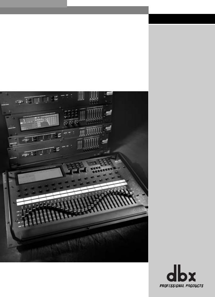
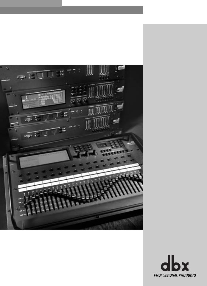
Congratulations on your purchase of the dbx DriveRack™ Complete Equalization and |
|
Loudspeaker Management System! For over 30 years, dbx has been the industry leader in |
||
|
||
|
dynamics processing. With the introduction of the DriveRack™ , dbx Professional Products has |
|
|
redefined the standard by which all other loud speaker management systems will be based |
|
|
This manual will be your guide to understanding the full functionality of the powerful 480, 481, |
|
|
482, 442 and 480R DriveRack™ units. By combining the different components, the configura- |
|
|
tion possibilities are limitless. After you have become familiar with the unit, we encourage you |
|
|
to experiment and find the most effective and efficient way to run your system by utilizing the |
|
|
powerful processing of the DriveRack™. |
1.1 Defining the DriveRack™ System
The dbx DriveRack™ is the most effective way to manage all aspects of post mix processing and signal routing. The following are just some of the features of the 480, 481, 482 and 480R.
480 DriveRack™ features:
•4 Input and 8 Outputs with routing
•31 band graphic or 9 band parametric equalizer on every input (pre-crossover)
•Dual Real Time Audio Analyzers
•Butterworth, Bessel or Linkwitz-Riley crossover filters
•27 Different Crossover Configurations
•Time Alignment and Transducer Alignment Delays
•Compressor/Limiter on every output
•Speaker Compensation EQ (post crossover)
•Multi-level Security System
•Separate House and Show EQ with individual lockouts
•Triple redundant back up of all parameters when running network, 480R and PC GUI
•TYPE IV™ Conversion System
•Electronically balanced/RF filtered XLR Inputs and Outputs
•Proprietary RS-485 Control Network
•RS-232 PC Interface for computer display and configuration
481 DriveRack™ features:
•4 Input and 8 Outputs with routing
•31 band graphic or 9 band parametric equalizer on every input (pre-crossover)
•Dual Real Time Audio Analyzers
•Butterworth, Bessel or Linkwitz-Riley crossover filters
•27 Different Crossover Configurations
®
ii |
DriveRack™ User Manual |
|
|

DriveRack™ |
Introduction |
•Time Alignment and Transducer Alignment Delays
•Compressor/Limiter on every output
•Speaker Compensation EQ (post crossover)
•Multi-level Security System
•Separate House and Show EQ with individual lockouts
•Triple redundant backup of all parameters when running network, 480R and PC GUI
•TYPE IV™ Conversion System
•Electronically balanced/RF filtered Euroblock Inputs and Outputs
•Proprietary RS-485 Control Network
•RS-232 PC Interface for computer display and configuration
482 DriveRack™ features:
•4 Input and 8 Outputs with routing
•31 band graphic or 9 band parametric equalizer on every input (pre-crossover)
•Dual Real Time Audio Analyzers
•Butterworth, Bessel or Linkwitz-Riley crossover filters
•27 Different Crossover Configurations
•Time Alignment and Transducer Alignment Delays
•Compressor/Limiter on every output
•Speaker Compensation EQ (post crossover)
•Multi-level Security System
•Separate House and Show EQ with individual lockouts
•Triple redundant back up of all parameters when running network, 480R and GUI
•TYPE IV™ Conversion System
•Electronically balanced/RF filtered XLR Inputs and Outputs
•Proprietary RS-485 Control Network
•RS-232 PC Interface for computer display and configuration
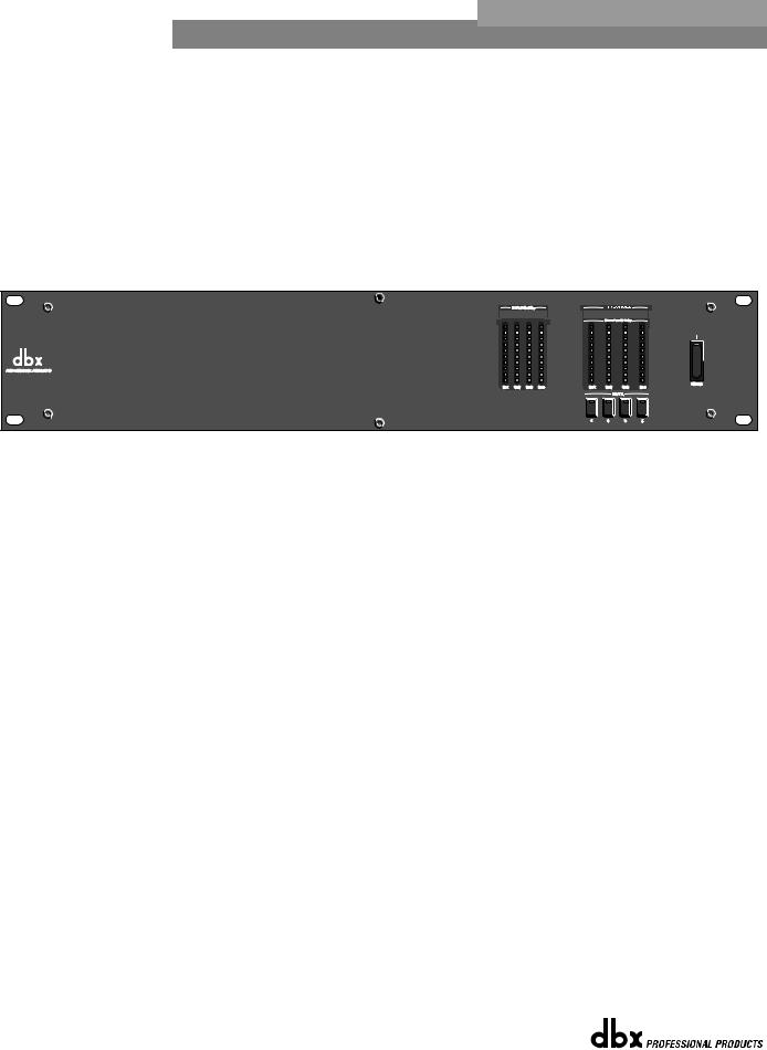
442 DriveRack™ features:
•4 Input and 4 Outputs
•31 band graphic or 9 band parametric equalizer on every input
•Time Alignment Delays
•Compressor/Limiter on every output
•Multi-level Security System
•Separate House and Show EQ with individual lockouts
•Triple redundant back up of all parameters when running network, 480R and GUI
•TYPE IV™ Conversion System
•Electronically balanced/RF filtered XLR Inputs and Outputs
•Proprietary RS-485 Control Network
•RS-232 PC Interface for computer display and configuration
®
DriveRack™ User Manual |
iii |
|
|

|
Introduction |
DriveRack |
™ |
|
|
||
|
|
|
|
|
|
|
|
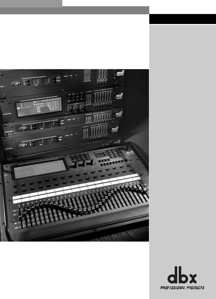
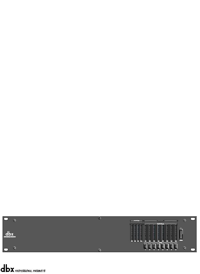
480R DriveRack™ features:
•Dedicated remote interface to control all 480, 481, 482 and 442 DriveRack™ units
•31 Motorized faders for equalization control
•32 assignable hot-keys with up to 64 different assignment capabilities
•Built-in Real Time Audio Analyzer (with rear-panel XLR connector)
•System Mute button
•Proprietary RS-485 Control Network
•RS-232 PC Interface for computer display and configuration
•480P Power Supply Included
•Responds to MIDI commands from mixing consoles including: Soundcraft™ SM20 and Series 5 and the Allen & Heath™ ML 4000 and ML5000
By including every form of processing necessary to drive the signal from the mixer to the power amp, the DriveRack™ allows you to eliminate all other processing devices that are normally found in large and cumbersome traditional DriveRack systems of the past.
The 480 DriveRack™ Loud Speaker Management System includes four balanced XLR inputs, as well as eight balanced XLR outputs, which can be routed for any configuration. The 481 and 482 DriveRack™ feature the identical processing power of the 480 DriveRack, but utilize streamline front panel interfaces. In addition, the 481 utilizes euroblock connectors as opposed to the XLR connectors found in the 480 and 482 DriveRack.
The 480, 481 and 482 DriveRacks™ include features such as: pre-crossover EQ, dual RTAs, notch filters, speaker delays, multiple crossovers and compression/limiting, as well as numerous other features. Dual RTA analyzers can be run simultaneously with RTA source inputs capable of being remotely switched on the fly. The 480 DriveRack™ is fully programmable from the front panel, and can control other devices in a network including the 481 and 482 slave units. In addition, the entire system can be controlled via the 480R DriveRack™ remote controller or through the included GUI interface.
The 442 DriveRack Equalization Management system is the perfect tool for monitor mixing applications. The 442 offers four balanced XLR inputs and four XLR outputs, with four independent channels of effect processing. Each channel offers a 31-band graphic or parametric equalizers, as well as digital delay and industry-standard, dbx dynamics processing.
1.2 Service Contact Info
If you require technical support, contact dbx Customer Service. Be prepared to accurately describe the problem. Know the serial number of your unit - this is printed on a sticker attached to the rear panel. If you have not already taken the time to fill out your warranty registration card and send it in, please do so now.
®
iv |
DriveRack™ User Manual |
|
|
DriveRack™ |
Introduction |
Section i |
Before you return a product to the factory for service, we recommend you refer to the manual. Make sure you have correctly followed installation steps and operation procedures. If you are still unable to solve a problem, contact our Customer Service Department at (801) 568-7660 for consultation. If you need to return a product to the factory for service, you MUST contact Customer Service to obtain a Return Authorization Number.
No returned products will be accepted at the factory without a Return Authorization Number.
Please refer to the Warranty below, which extends to the first end-user. After expiration of the warranty, a reasonable charge will be made for parts, labor, and packing if you choose to use the factory service facility. In all cases, you are responsible for transportation charges to the factory. dbx will pay return shipping if the unit is still under warranty.
Use the original packing material if it is available. Mark the package with the name of the shipper and with these words in red: DELICATE INSTRUMENT, FRAGILE! Insure the package properly. Ship prepaid, not collect. Do not ship parcel post.
1.3 Warranty
This warranty is valid only for the original purchaser and only in the United States.
1.The warranty registration card that accompanies this product must be mailed within 30 days after purchase date to validate this warranty. Proof-of-purchase is considered to be the burden of the consumer.
2.dbx warrants this product, when bought and used solely within the U.S., to be free from defects in materials and workmanship under normal use and service.
3.dbx liability under this warranty is limited to repairing or, at our discretion, replacing defective materials that show evidence of defect, provided the product is returned to dbx WITH RETURN AUTHORIZATION from the factory, where all parts and labor will be covered up to a period of two years. A Return Authorization number must be obtained from dbx by telephone. The company shall not be liable for any consequential damage as a result of the product's use in any circuit or assembly.
4.dbx reserves the right to make changes in design or make additions to or improvements upon this product without incurring any obligation to install the same additions or improvements on products previously manufactured.
5.The foregoing is in lieu of all other warranties, expressed or implied, and dbx neither assumes nor authorizes any person to assume on its behalf any obligation or liability in connection with the sale of this product. In no event shall dbx or its dealers be liable for special or consequential damages or from any delay in the performance of this warranty due to causes beyond their control.
®
DriveRack™ User Manual
v

Section i |
Introduction |
DriveRack |
™ |
|
|||
|
|
|
|
|
|
|
|
®
vi |
DriveRack™ User Manual |
|
|
DriveRack™ |
Section 1 |
Getting Started
®
Section 1 |
Getting Started |
DriveRack |
™ |
|
|||
|
|
|
|
|
|
|
|
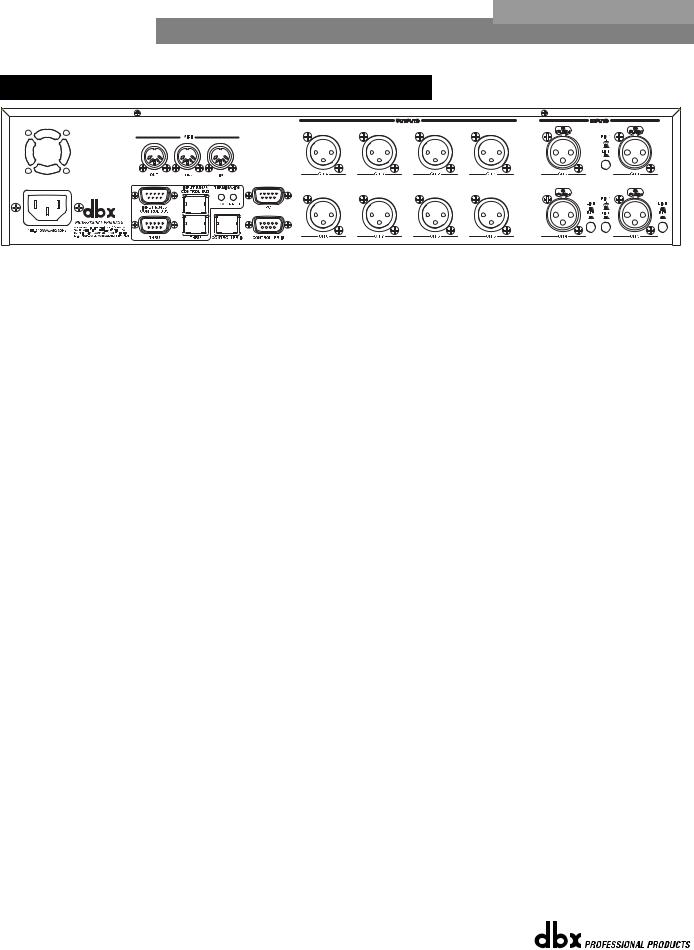
1.1 Rear Panel Connections (480)
35 WATTS |
IEC Power Cord Receptacle
The 480 comes with an International power supply that will accept voltages ranging from 100V240V at frequencies from 50Hz-60Hz. An IEC cord is included.
MIDI In, Out and Thru Connectors
These connectors provide MIDI functionality to the 480 DriveRack™. The In, Out and Thru jacks allow you to use the 480 DriveRack™ at any point in the MIDI chain.
RS485 Control Bus Input (DB-9 connector type)
This input network connection is used to receive information being sent from other units in the DriveRack™ network link.
RS485 Control Thru Bus (DB-9 connector type)
This Thru network connection is used to pass information to other units in the DriveRack™ network link.
RS485 Control Bus Input (RJ-45 connector type)
This input network connection is used to receive information being sent from other units in the DriveRack™ network link.
RS485 Control Thru Bus (RJ-45 connector type)
This Thru network connection is used to pass information to other units in the DriveRack™ network link.
Termination LEDs
These LEDS indicate when network is properly terminated. The Green LED indicates that the network has been correctly terminated.
Remote Controller In Connection
This DB-9 type input connection is used to send and receive information from the 480R Remote Control unit.
PC Connection
This DB-9 type connection is used to send and receive information to and from the GUI interface.
Outputs 1-8
The output section of the 480 DriveRack™ offers eight electronically balanced XLR connectors.
®
2 |
DriveRack™ User Manual |
|
|
DriveRack™ |
Getting Started |
Section 1 |
Inputs 1-4
The input section of the 480 DriveRack™ offers four electronically balanced XLR connectors. Inputs 3 and 4 offer Line/RTA switches that allow you to run a real time audio analyzer microphone directly into the input of the 480 DriveRack™. The four XLR inputs of the 480 DriveRack™ also offer Pin 1 lift switches which lift the ground of the selected XLR input pair when pressed.
WARNING - For proper operation of the RTA microphone, the RTA button must be depressed and the ground /lift switch must be in the grounded position. When the RTA button on the back panel is depressed, 48V phantom power is applied to pins 2 and 3 of the XLR connector. To maintain a proper ground return for the phantom power, the ground/lift switch must be in the grounded position. This will prevent the possibility of electrical shock.
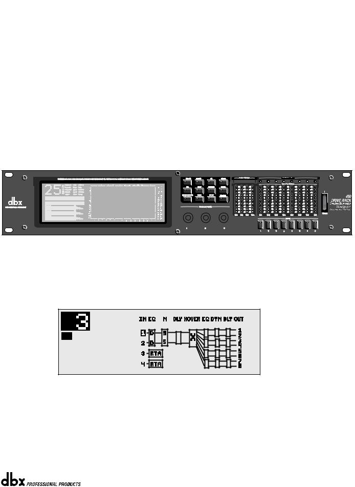
1.2 Front Panel (480)
LCD Display
The large LCD display of the 480 DriveRack™ provides the user with all of the vital processing information of the DriveRack™ including: signal routing, configuration modes, effect block editing and RTA displays. The top left corner of the display indicates network device ID numbers. The reverse background number indicates the number of the slave unit being controlled, while Mst indicates that the unit is set to act as the master.
|
|
25 |
40 |
63 |
|
100 |
160 |
250 |
400 |
630 |
|
1.0k |
1.5k |
2.5k |
4.0k |
6.3k |
10k |
16k |
|
|
|
|
+14 |
|
|
|
|
|
|
|
|
|
|
|
|
|
|
|
|
+24 |
+6 |
|
|
|
|
|
|
|
|
|
|
|
|
|
|
|
|
|
|
|
|
|
|
|
+12 |
|
|
|
|
|
|
|
|
|
|
|
|
|
|
|
|
+18 |
+4 |
|
|
|
|
|
|
|
|
|
|
|
|
|
|
|
|
|
|
+12 |
+2 |
|
|
|
+10 |
|
|
|
|
|
|
|
|
|
|
|
|
|
|
|
|
||
|
|
|
|
|
|
|
|
|
|
|
|
|
|
|
|
|
|
|
|
|
|
|
+8 |
|
|
|
|
|
|
|
|
|
|
|
|
|
|
|
|
+8 |
0 |
|
|
|
|
|
|
|
|
|
|
|
|
|
|
|
|
|
|
0 |
-2 |
|
|
|
+6 |
|
|
|
|
|
|
|
|
|
|
|
|
|
|
|
|
||
|
|
|
|
|
|
|
|
|
|
|
|
|
|
|
|
|
|
-8 |
-4 |
|
F7 |
4-Way FOH w/RTA |
+4 |
|
|
|
|
|
|
|
|
|
|
|
|
|
|
|
|
||
|
|
|
|
|
|
|
|
|
|
|
|
|
|
|
|
-12 |
-8 |
|||
+2 |
|
|
|
|
|
|
|
|
|
|
|
|
|
|
|
|
||||
|
|
|
|
|
|
|
|
|
|
|
|
|
|
|
|
-18 |
-9 |
|||
|
|
0 |
|
|
|
|
|
|
|
|
|
|
|
|
|
|
|
|
||
|
|
|
|
|
|
|
|
|
|
|
|
|
|
|
|
|
|
-24 |
-12 |
|
|
|
-2 |
|
|
|
|
|
|
|
|
|
|
|
|
|
|
|
|
||
Parameter 1 |
|
|
|
|
|
|
|
|
|
|
|
|
|
|
|
|
|
|
|
|
|
-4 |
|
|
|
|
|
|
|
|
|
|
|
|
|
|
|
|
-30 |
-15 |
|
|
|
|
|
|
|
|
|
|
|
|
|
|
|
|
|
|
|
-40 |
-20 |
|
|
-6 |
|
|
|
|
|
|
|
|
|
|
|
|
|
|
|
|
|||
|
|
|
|
|
|
|
|
|
|
|
|
|
|
|
|
|
-50 |
-25 |
||
Parameter 2 |
|
-8 |
|
|
|
|
|
|
|
|
|
|
|
|
|
|
|
|
||
|
|
|
|
|
|
|
|
|
|
|
|
|
|
|
|
|
-60 |
-30 |
||
Single RTA |
-10 |
|
|
|
|
|
|
|
|
|
|
|
|
|
|
|
|
|||
|
|
|
|
|
|
|
|
|
|
|
|
|
|
|
|
-70 |
-35 |
|||
-12 |
|
|
|
|
|
|
|
|
|
|
|
|
|
|
|
|
||||
Parameter 3 |
|
-14 |
|
|
|
|
|
|
|
|
|
|
|
|
|
|
|
|
-80 |
-40 |
Channel 1 |
|
|
|
|
|
|
|
|
|
|
|
|
|
|
|
|
|
|
||
|
|
|
|
|
|
|
|
|
|
|
|
|
|
|
|
|
-90 |
-50 |
||
20 |
31 |
50 |
80 |
125 |
200 |
|
315 |
500 |
800 |
1.3k |
|
2.0k |
3.2k |
5.0k |
8.0k |
13k |
20k |
|
||
Function Buttons
The function buttons of the 480 DriveRack™ allow access to all editing and navigating functions of the 480 DriveRack™.
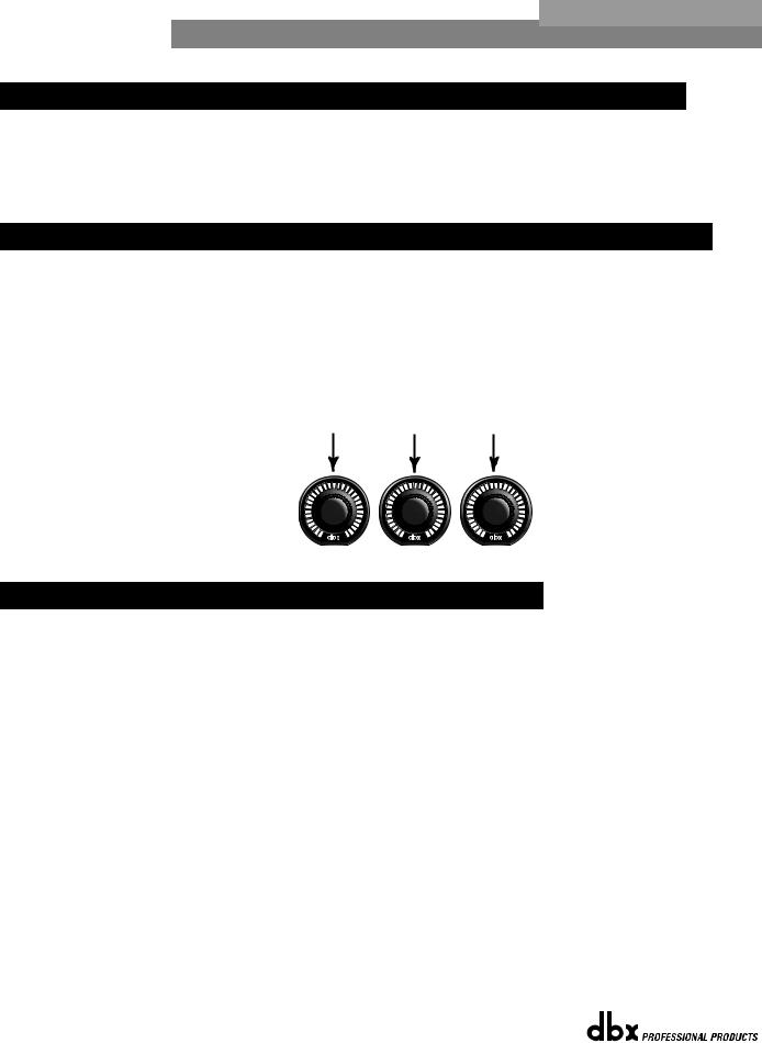
Parameter Knobs
The parameter knobs of the 480 DriveRack™ allow the user to edit parameters of selected effects of the 480 DriveRack™. The parameter knobs of the 480 and 480R DriveRack™ units also incorporate light display Logicators™ which surround the knob itself and indicate levels of parameter and effect activity. The parameter knobs of the 480 DriveRack™ also provide the
®
DriveRack™ User Manual |
3 |
|
|
Section 1 |
Getting Started |
DriveRack |
™ |
|
|||
|
|
|
|
|
|
|
|
user with different modes of functionality including: coarse/fine encoding (successive presses will toggle the knob between a fast and slow mode of operation) and horizontal-vertical navigators, which allow the parameter buttons (when used in program and configuration mode) to navigate the program screen horizontally and vertically.
Input Meters
The 480 DriveRack™ provides the user with four independent 12 segment Lightpipe™ input meters that range from -30 to +22 dBu. Note: These meters are calibrated for the +22dBu setting of the gain jumpers.
Threshold Meters
The threshold meters indicate that the threshold level has been exceeded within the dynamics section (compressor/limiter), and gain reduction is taking place within the specific output channel.
Output Meters
The 480 DriveRack™ provides the user with eight independent 12-seg- ment Lightpipe™ output meters that range from -30 to +22 dBu. Note: These meters are calibrated for the +22dBu setting of the gain jumpers.
Output Mutes
The eight output mute buttons are used for independently muting each output on all eight outputs of the 480 DriveRack™.
Power Switch
Turns the 480 DriveRack™ on and off. Note: dbx Professional Products recommends that power amps connected to the DriveRack™, should be powered down prior to cycling the DriveRack™.
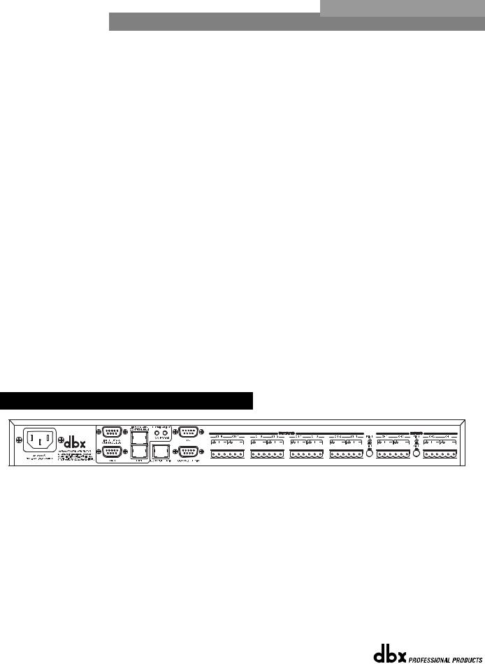
1.3 Rear Panel Connections (481)
IEC Power Cord Receptacle
The 481 comes with an International power supply that will accept voltages ranging from 100V240V at frequencies from 50Hz-60Hz. An IEC cord is included.
RS485 Control Bus Input (DB-9 connector type)
This input network connection is used to receive information being sent from other units in the DriveRack™ network link.
RS485 Control Thru Bus (DB-9 connector type)
This Thru network connection is used to pass information to other units in the DriveRack™ network link.
RS485 Control Bus Input (RJ-45 connector type)
®
4 |
DriveRack™ User Manual |
|
|
DriveRack™ |
Getting Started |
Section 1 |
This input network connection is used to receive information being sent from other units in the DriveRack™ network link.
RS485 Control Thru Bus (RJ-45 connector type)
This Thru network connection is used to pass information to other units in the DriveRack™ network link.
Termination LEDs
These LEDS indicate when network is properly terminated. The Green LED indicates that the network has been correctly terminated.
Remote Controller In Connection
This DB-9 type input connection is used to send and receive information from the 480 Remote DriveRack™ Unit.
Outputs 1-8 (Euroblock Connectors)
The output section of the 481 DriveRack™ offers eight electronically balanced Euroblock connectors.
Inputs 1-4
The input section of the 481 DriveRack™ offers four electronically balanced Euroblock connectors.
Ground Lift Switch
This switch (when pressed in), is used to lift the Pin one ground on either inputs 1 and 2 or 3 and 4.
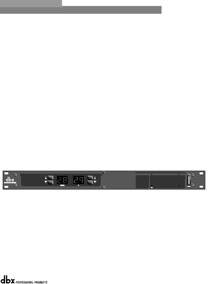
1.4 Front Panel (481)
PC Connection
This DB-9 type connection is used to send and receive information to and from the GUI interface.
Program Up and Down
These program up and down buttons are used to scroll through the program menu of the 481.
Program Display
This program display is used to indicate the currently selected program of the 481.
ID Display
This ID display is used to indicate the current assigned identification of the 481. This identification is essential for unit recognition when the 481 is used in a network system.
Control Bus LED
®
DriveRack™ User Manual |
5 |
|
|

Section 1 |
Getting Started |
DriveRack |
™ |
|
|||
|
|
|
|
|
|
|
|
This LED (when lit), indicates that the 481 is connected to the control bus.
When it is flashing, the 481 is sending/receiving network information.
Remote LED
This LED (when lit), indicates that the 481 is connected to the 480R. When it is flashing, the 481 is sending/receiving information from the 480R.
PC LED
This LED (when lit), indicates that the 481 is connected to the PC. When it is flashing, the 481 is sending/receiving information from the PC.
Input Meters
The 481 DriveRack™ provides the user with four independent 6-segment lightpipe™ input meters that range from -30 to +22 dBu. Note: These meters are calibrated for the +22dBu setting of the gain jumpers.
Output Meters
The 481 DriveRack™ provides the user with eight independent 6-segment lightpipe™ output meters that range from -30 to +22 dBu. Note: These meters are calibrated for the +22dBu setting of the gain jumpers.
Power Switch
Turns the 481 DriveRack™ on and off. Note: dbx Professional Products recommends that power amps connected to the DriveRack™ should be powered down prior to cycling the DriveRack™.
1.5 Rear Panel Connections (482)
IEC Power Cord Receptacle
The 482 comes with an International power supply that will accept voltages ranging from 100V-240V at frequencies from 50Hz-60Hz. An IEC cord is included.
MIDI In, Out and Thru Connectors
These connectors provide MIDI functionality to the 482 DriveRack™. The In, Out and Thru jacks allow you to use the 482 DriveRack™ at any point in the MIDI chain.
RS485 Control Bus Input (DB-9 connector type)
This input network connection is used to receive information being sent from other units in the DriveRack™ network link.
®
6
DriveRack™ |
Getting Started |
Section 1 |
RS485 Control Thru Bus (DB-9 connector type)
This Thru network connection is used to pass information to other units in the DriveRack™ network link.
RS485 Control Bus Input (RJ-45 connector type)
This input network connection is used to receive information being sent from other units in the DriveRack™ network link.
RS485 Control Thru Bus (RJ-45 connector type)
This Thru network connection is used to pass information to other units in the DriveRack™ network link.
Termination LEDs
These LEDS indicate when network is properly terminated. The Green LED indicates that the network has been correctly terminated.
Remote Controller In Connection
This DB-9 type input connection is used to send and receive information from the 480 Remote DriveRack™ Unit.
PC Connection
This DB-9 type connection is used to send and receive information to and from the GUI interface.
Outputs 1-8
The output section of the 482 DriveRack™ offers eight electronically balanced XLR connectors.
Inputs 1-4
The input section of the 482 DriveRack™ offers four electronically balanced XLR connectors. Inputs 3 and 4 offer Line/RTA switches that allow you to run a real time audio analyzer microphone directly into the input of the 482 DriveRack™. The four XLR inputs of the 482 DriveRack™ also offer Pin 1 lift switches which lift the ground of the selected XLR input pair when pressed.
Warning - For proper operation of the RTA microphone, the RTA button must be depressed and the ground /lift switch must be in the grounded position. When the RTA button on the back panel is depressed, 48V phantom power is applied to pins 2 and 3 of the XLR connector. To maintain a proper ground return for the phantom power, the ground/lift switch must be in the grounded position. This will prevent the possibility of electrical shock.
1.6 Front Panel (482)
®
7

Section 1 |
Getting Started |
DriveRack |
™ |
|
|||
|
|
|
|
|
|
|
|
PC Connection
This DB-9 type connection is used to send and receive information to and from the GUI interface.
Program Up and Down
These program up and down buttons are used to scroll through the program menu of the 482.
Program Display
This program display is used to indicate the currently selected program of the 482.
ID Display
This ID display is used to indicate the current assigned identification of the 482. This identification is essential for unit recognition when the 482 is used in a network system.
Control Bus LED
This LED (when lit), indicates that the 482 is connected to the control bus. When it is flashing, the 482 is sending/receiving network information.
Remote LED
This LED (when lit), indicates that the 482 is connected to the 480R. When it is flashing, the 482 is sending/receiving information from the 480R.
PC LED
This LED (when lit), indicates that the 482 is connected to the PC. When it is flashing, the 482 is sending/receiving information from the PC.
Input Meters
The 482 provides the user with four independent 12 segment lightpipe™ input meters that range from -30 to +22 dBu. Note: These meters are calibrated for the +22dBu setting of the gain jumpers.
Threshold Meters
The threshold meters indicate that the threshold level has been exceeded within the dynamics section (compressor/limiter), and gain reduction is taking place within the specific output channel.
Output Meters
The 482 DriveRack™ provides the user with eight independent 12-seg- ment lightpipe™ output meters that range from -30 to +22 dBu. Note: These meters are calibrated for the +22dBu setting of the gain jumpers.
Output Mutes
The eight output mute buttons are used for independently muting each output of the 482 DriveRack™.
Power Switch
Turns the 482 DriveRack™ on and off. Note: dbx Professional Products recommends that power amps connected to the DriveRack™ should be powered down prior to cycling the DriveRack™.
®
8 |
DriveRack™ User Manual |
|
|
DriveRack™ |
Getting Started |
SECTION 1
1.7 Rear Panel Connections (442)
35 WATTS
IEC Power Cord Receptacle
The 442 comes with an International power supply that will accept voltages ranging from 100V240V at frequencies from 50Hz-60Hz. An IEC cord is included.
MIDI In, Out and Thru Connectors
These connectors provide MIDI functionality to the 442 DriveRack™. The In, Out and Thru jacks allow you to use the 442 DriveRack™ at any point in the MIDI chain.
RS485 Control Bus Input (DB-9 connector type)
This input network connection is used to receive information being sent from other units in the DriveRack™ network link.
RS485 Control Thru Bus (DB-9 connector type)
This Thru network connection is used to pass information to other units in the DriveRack™ network link.
RS485 Control Bus Input (RJ-45 connector type)
This input network connection is used to receive information being sent from other units in the DriveRack™ network link.
RS485 Control Thru Bus (RJ-45 connector type)
This Thru network connection is used to pass information to other units in the DriveRack™ network link.
Termination LEDs
These LEDS indicate when network is properly terminated. The Green LED indicates that the network has been correctly terminated.
Remote Controller In Connection
This DB-9 type input connection is used to send and receive information from the 480 Remote DriveRack™ Unit.
PC Connection
This DB-9 type connection is used to send and receive information to and from the GUI interface.
®
DriveRack™ User Manual |
9 |
|
|
SECTION 1 |
Getting Started |
DriveRack |
™ |
|
|||
|
|
|
|
|
|
|
|
Outputs 1-4
The output section of the 442 DriveRack™ offers four electronically balanced XLR connectors.
Inputs 1-4
The input section of the 442 DriveRack™ offers four electronically balanced XLR connectors. The four XLR inputs of the 442 DriveRack™ also offer Pin 1 lift switches which lift the ground of the selected XLR input pair when pressed.
1.8 Front Panel (442)
PC Connection
This DB-9 type connection is used to send and receive information to and from the GUI interface.
Program Up and Down
These program up and down buttons are used to scroll through the program menu of the 442.
Program Display
This program display is used to indicate the currently selected program of the 442.
ID Display
This ID display is used to indicate the current assigned identification of the 442. This identification is essential for unit recognition when the 442 is used in a network system.
Control Bus LED
This LED (when lit), indicates that the 442 is connected to the control bus. When it is flashing, the 442 is sending/receiving network information.
Remote LED
This LED (when lit), indicates that the 442 is connected to the 480R. When it is flashing, the 442 is sending/receiving information from the 480R.
PC LED
This LED (when lit), indicates that the 442 is connected to the PC.
When it is flashing, the 442 is sending/receiving information from the
PC.
®
10 |
DriveRack™ User Manual |
|
|

DriveRack™ |
Getting Started |
SECTION 1
Input Meters
The 442 provides the user with four independent 12 segment lightpipe™ input meters that range from -30 to +22 dBu. Note: These meters are calibrated for the +22dBu setting of the gain jumpers.
Threshold Meters
The threshold meters indicate that the threshold level has been exceeded within the dynamics section (compressor/limiter), and gain reduction is taking place within the specific output channel.
Output Meters
The 442 DriveRack™ provides the user with four independent 12-segment lightpipe™ output meters that range from -30 to +22 dBu. Note: These meters are calibrated for the +22dBu setting of the gain jumpers.
Output Mutes
The four output mute buttons are used for independently muting each output of the 442 DriveRack™.
Power Switch
Turns the 442 DriveRack™ on and off. Note: dbx Professional Products recommends that power amps connected to the DriveRack™ should be powered down prior to cycling the DriveRack™.
®
DriveRack™ User Manual |
11 |
|
|

SECTION 1 |
Getting Started |
DriveRack |
™ |
|
|||
|
|
|
|
|
|
|
|
®
12 |
DriveRack™ User Manual |
|
|
DriveRack™ |
Section 2 |
|
Editing Functions |
|
EDITING |
|
FUNCTIONS |
®

Section 2 |
Editing Functions |
DriveRack |
™ |
|
|||
|
|
|
|
|
|
|
|
Editing
Functions
The 480 DriveRack™ has been carefully designed and engineered to ensure that all aspects of operation are intuitive and logical. Simply stated, the 480 DriveRack™ operating system was designed with user’s best interest in mind. Editing the 480 DriveRack™ can be done by utilizing key functions and tools. This section will provide you with detailed information on all of the tools used to optimize the editing performance of your DriveRack™. This intuitive front panel interface can also be used to control other units (481, 482 and 442) which are used within a a DriveRack™ network system.
2.1 Basic Navigation Modes
Navigational aspects of the 480 DriveRack™ are clear, concise and more important: flexible. The DriveRack™ provides you with essentially three different modes of navigation when performing programming edits. 1. FX buttons - This array of 12 FX buttons is your primary mode of accessing any effect module. 2. NEXTPG & PREVPG page buttons - Successive presses of the NEXTPG or PREVPG page buttons will move the user from one page to the next in an effect block. 3. PARAMETER KNOBS - In addition to editing parameter values with the PARAMETER knobs, the PARAMETER 2 & 3 knobs (when used in program mode) will move the cursor throughout the display horizontally and vertically. For more information on this unique feature, please see section 2.4.
2.2 FX Button Array Overview
The following sections will provide you with detailed information for accurate navigation of the FX button section of the 480 DriveRack™. Each diagram indicates the functionality of each FX button and its ability to guide the user through each operational menu.
®
14 |
DriveRack™ User Manual |
|
|

DriveRack™ |
Editing Functions |
Section 2 |
2.2 FX Button Array Overview (cont.)
 PREVIOUS PAGE - Moves to the previous page in the currently selected effect menu.
 NEXT PAGE - Moves to the next page in the currently selected effect menu.
EQ - Selects the EQ effect menu. Successive presses will rotate through the various
EQ modules.
XOVER - Selects the Cross over menu. Successive presses will toggle between the various crossovers. Note: when used as a controller for the 442, pressing the X-over button will access the notch filter section of the 442.
RTA - Enters the RTA mode of the DriveRack. Successive presses will toggle between the RTA modules.
DELAY - Selects the DELAY effect menu. Successive presses will toggle between the various delay modules.
DYNAMICS - Selects the Compressor/Limiter effect menu. Successive presses will move through the dynamics modules.
 OTHER - Selects the Input and Output editing sections of the DriveRack™.


 PROGRAM/CONFIG - This button will load a selected program, loads the Program
  mode or enters the Configuration edit mode when pressed and held.
 STORE - The STORE button is used to store program edits.
 UTILITY - Selects the Utility edit menu of the DriveRack.
COMPARE - The Compare button is used to compare program edits to the original (unedited) program.
PARAMETER KNOBS changes (parameter 1), knobs 2 and 3.
- The parameter knobs perform various functions including: program parameter value edits and cursor navigation utilizing the parameter
®
DriveRack™ User Manual |
15 |
|
|
Section 2 |
Editing Functions |
DriveRack |
™ |
|
|||
|
|
|
|
|
|
|
|
2.3 Parameter Knob Encoders Coarse/Fine Operation
The parameter knob encoders of the 480 and 480R DriveRack™ Remote provide the user with the option of coarse or fine performance modes. This means that the parameter knobs can be set to either move or change values at a rapid (coarse) or slower (fine) rate. This option can be selected in any mode by simply pressing the selected parameter knob. Successive presses will toggle between coarse and fine mode.
2.4 Parameter Knobs (Horizontal-Vertical Navigation Mode)
The 480 DriveRack™ offers the horizontal-vertical navigation feature which helps streamline navigation and editing of the unit. The Horizontal-Vertical Navigation mode allows the user to use the parameter knobs (2&3) to quickly navigate through the program/configuration menu of any DriveRack™ unit. This feature can be used to navigate the display screen in program or configuration mode. To utilize this feature, simply select the high-lighted cursor, then use the PARAMETER 2 knob to move the cursor left and right, and use the PARAMETER 3 knob to move the cursor up and down while the unit is in Program or Configuration mode.
Select Left-Right Up-Down
1 |
2 |
3 |
2.5 Copy/Paste Functionality
The front panel of the 480 and 480R allow you to copy and paste the parameter value settings for entire effect module blocks, and then paste them into another block. Note that the information from one module must be pasted into a similar module, ie; from one dynamic module to another. This function can be performed in a single unit, or to any unit in a network setup. The procedure for cut and paste is as follows:
•From program mode, use the PARAMETER knobs to navigate to the desired module.
•Once the desired module has been selected, press and hold the PREVIOUS PAGE button until the display reads: COPY.
•The information is now held in what is commonly known as the “pasteboard.”
•At this point, navigate to the unit that you wish to paste the information into using the
PARAMETERS knobs.
•If you are pasting into a unit within the network, either enter in the device id# (key pad on the 480R, or from the Utility page in the 480).
•Once the desired module has been selected, press and hold the NEXT PAGE button and the display will read: PASTE.
®
16 |
DriveRack™ User Manual |
|
|

DriveRack™ |
Editing Functions |
Section 2 |
|
|
|
|
|
|
2.6 Navigating the EQ Sections |
|
|
|
|
|
|
Navigating the "EQ and Notch Filter Sections"
To edit the parameters of the EQs and Notch Filters used in a selected program, simply use the following procedure. From program mode, either press the EQ button or use the Parameter 2 or 3 knobs to move to EQ module to be edited. Once you have reached the desired EQ,
press the Parameter 2 or 3 knob. Successive presses of the EQ button will move through each channel (input or output) that utilizes an EQ module. Navigate throughthe Pages of the selected EQ section by pressing "Next Page" or "Prev Page" successively until arriving at the desired Page.
|
|
|
|
EQ |
|
|
|
|
|
|
|
|
|
|
|
|
|
|
|
The EQ button |
|
|
|
|
GEQ |
EQ On/Off |
|
Frequency |
|
|
Boom |
|
|
|
|
|
|
||
|
|
|
|
|
|
|
|
|
|
|
|
||||||||
|
|
|
|
Flat Set/Undo |
|
Level |
|
|
Zizz |
|
|
|
|
|
|
||||
toggles through |
|
|
|
|
|
|
|
|
|
|
|
|
|
||||||
|
|
|
|
|
|
|
|
|
|
|
|
|
|
|
|
|
|
|
|
the EQs or notch |
|
|
|
|
|
|
|
|
|
|
|
|
|
|
|
|
|
|
|
|
|
|
EQ |
|
|
|
|
|
|
|
|
|
|
|
|
|
|
||
filters used in |
|
|
|
|
|
|
|
|
|
|
|
|
|
|
|
|
|
||
|
|
|
|
|
|
|
|
|
|
|
|
|
|
|
|
|
|
|
|
each channel of |
|
|
|
|
PEQ |
EQ On/Off |
|
Band 1 Freq |
|
|
Band 2 Freq |
|
Band 3 Freq |
|
Band 4 Freq |
|
|||
|
|
|
|
Type |
|
Slope |
|
|
Q |
|
Q |
|
Q |
|
|||||
the selected |
|
|
|
|
|
|
|
|
|
|
|||||||||
program |
|
|
|
|
|
Flat Set/Undo |
|
Level |
|
|
Level |
|
Level |
|
Level |
|
|||
|
|
|
EQ |
|
|
|
|
|
|
|
|
|
|
|
|
|
|
||
menu. |
|
|
|
|
|
|
|
|
|
|
|
|
|
|
|
|
|
||
|
|
|
|
|
|
|
|
|
|
|
|
|
|
|
|
|
|
|
|
|
|
|
|
|
|
Band 5 Freq |
|
Band 6 Freq |
|
|
Band 7 Freq |
|
Band 8 Freq |
|
Band 9 Freq |
|
|||
|
|
|
|
|
|
|
|
|
|
Band 9 Freq |
|
Slope |
|
||||||
|
|
|
|
|
|
Q |
|
Q |
|
|
Q |
|
Q |
|
|
||||
|
|
|
|
|
|
|
|
|
|
Slope |
|
Level |
|
||||||
|
|
|
|
|
|
Level |
|
Level |
|
|
Level |
|
Level |
|
|
||||
|
|
|
|
|
|
|
|
|
|
Level |
|
|
|
||||||
|
|
|
|
|
|
|
|
|
|
|
|
|
|
|
|
|
|
|
|
|
|
|
|
|
|
|
|
|
|
|
|
|
|
|
|
|
|
|
|
|
|
|
|
|
NOTCH |
Notch On/Off |
|
Notch1 Freq |
|
|
Notch 2 Freq |
|
|
|
|
|
|
||
|
|
|
|
|
|
|
|
Q Adjust |
|
|
Q Adjust |
|
|
|
|
|
|
||
|
|
|
|
|
|
|
|
|
Level |
|
|
Level |
|
|
|
|
|
|
|
|
|
|
|
|
|
|
|
|
|
|
|
|
|
|
|
Post XOVER |
|||
|
|
|
|
EQ |
|
|
|
|
|
|
|
|
|
|
|||||
|
|
|
|
|
|
|
|
|
|
|
|
|
|
|
|
|
|
||
|
|
|
|
|
PEQ |
EQ On/Off |
|
Band 1 Freq |
|
|
Band 2 Freq |
|
Band 3 Freq |
|
Band 4 Freq |
|
|||
|
|
|
|
|
|
|
|
|
|||||||||||
|
|
|
|
|
Type |
|
Q Adjust |
|
|
Q Adjust |
|
Q Adjust |
|
Q Adjust |
|
||||
|
|
|
|
|
|
Flat Set/Undo |
|
Level |
|
|
Level |
|
Level |
|
Level |
|
|||
|
|
|
|
|
|
|
|
|
|
|
|
|
|
|
|
|
|
|
|
The PARAMETER knobs are used to edit parameter values
1 |
2 |
3 |
®
DriveRack™ User Manual |
17 |
|
|

Section 2 |
Editing Functions |
DriveRack |
™ |
|
|||
|
|
|
|
|
|
|
|
2.7 Navigating the XOVER
Navigating the "X-OVER Section"
To edit the parameters of the Crossover used in a selected program, simply use the following procedure. From program mode,
either press the X-OVER button or use the Parameter 2 or 3 knobs to move to Crossover module. Once you have reached the Crossover module, press the Parameter 2 or 3 buttons to access the editing pages of the module. Navigate through the Pages of the selected Crossover
module by pressing the "Next Page" or "Prev Page" buttons successively until arriving at the desired Page.
The X-OVER button |
|
|
|
|
|
|
|
|
|
|
|
|
|
|
|
|
|
|
|
Filter - Dual Filter |
|
|
|
||||
|
|
|
|
X-OVER |
|
|
|
|
|
|
|
|
|
|
|
|
|
||||||||||
toggles through |
|
|
|
|
|
|
|
|
|
|
|
|
|
|
|
|
|
|
|
|
|
|
|
|
|||
|
|
|
|
|
|
|
|
|
|
|
|
|
|
|
|
|
|
|
|
|
|
|
|
|
|
|
|
the Crossover |
|
|
|
|
|
|
X-OVER |
Filter Type |
|
Lowpass |
|
Low Slope |
|
|
|
|
|
|
|
|
|
|
|
|
|
||
modules used in |
|
|
|
|
|
|
|
|
Highpass |
|
High Slope |
|
|
|
|
|
|
|
|
|
|
|
|
|
|||
each channel of |
|
|
|
|
|
|
|
|
|
|
|
|
|
|
|
|
|
|
|
|
|
|
|
|
|
|
|
the selected |
|
|
|
|
|
|
|
|
|
|
|
|
|
|
|
|
|
|
|
|
|
|
|
|
|
|
|
program. |
|
|
|
|
|
|
|
|
|
|
|
|
|
|
|
|
|
|
|
1X2... X-OVER |
|
|
|
||||
|
|
|
|
|
X-OVER |
|
|
|
|
|
|
|
|
|
|
|
|
|
|
|
|||||||
|
|
|
|
|
|
|
|
|
|
|
|
|
|
|
|
|
|
|
|
|
|
|
|
|
|||
|
|
|
|
|
|
|
|
|
|
|
|
|
|
|
|
|
|
|
|
|
|
|
|
|
|
|
|
|
|
|
|
|
|
|
X-OVER |
Low Fc |
|
Type |
|
|
|
|
|
|
|
|
|
|
|
|
|
|
|
|
|
|
|
|
|
|
|
|
Center Fc |
|
Low Slope |
|
|
|
|
|
|
|
|
|
|
|
|
|
|
|
|
||
|
|
|
|
|
|
|
|
High Fc |
|
High Slope |
|
|
|
|
|
|
|
|
|
|
|
|
|
|
|
|
|
|
|
|
|
|
|
|
|
|
|
|
|
|
|
|
|
|
|
|
|
1X3... X-OVER |
|
|
|
||||
|
|
|
|
|
X-OVER |
|
|
|
|
|
|
|
|
|
|
|
|
|
|
||||||||
|
|
|
|
|
|
|
|
|
|
|
|
|
|
|
|
|
|
|
|
|
|
|
|
|
|||
|
|
|
|
|
|
|
|
Low1 Fc |
|
Type |
|
Low2 Fc |
|
|
Type |
|
|
|
|
|
|
||||||
|
|
|
|
|
|
|
|
|
|
|
|
|
|
|
|
|
|||||||||||
|
|
|
|
|
|
|
X-OVER |
Center1 Fc |
|
Low1 Slope |
|
Center2 Fc |
|
|
Low2 Slope |
|
|
|
|
|
|
||||||
|
|
|
|
|
|
|
|
High1 Fc |
|
High1 Slope |
|
High2 Fc |
|
|
High2 Slope |
|
|
|
|
|
|
||||||
|
|
|
|
|
|
|
|
|
|
|
|
|
|
|
|
|
|
|
|
|
|
|
|
|
|
|
|
|
|
|
|
|
|
|
|
|
|
|
|
|
|
|
|
|
|
|
|
1X4... X-OVER |
|
|
|
||||
|
|
|
|
|
X-OVER |
|
|
|
|
|
|
|
|
|
|
|
|
|
|
|
|||||||
|
|
|
|
|
|
|
|
|
|
|
|
|
|
|
|
|
|
|
|
|
|
|
|
|
|||
|
|
|
|
|
|
|
|
Low1 Fc |
|
Type |
|
|
Low2 Fc |
|
|
|
Type |
|
|
|
Low3 Fc |
|
|
Type |
|||
|
|
|
|
|
|
|
X-OVER |
Center1 Fc |
|
Low1 Slope |
|
|
Center2 Fc |
|
|
|
Low2 Slope |
|
|
|
Center3 Fc |
|
|
Low3 Slope |
|||
|
|
|
|
|
|
|
High1 Fc |
|
High1 Slope |
|
|
High2 Fc |
|
|
|
High2 Slope |
|
|
|
High3 Fc |
|
|
High3 Slope |
||||
|
|
|
|
|
|
|
|
|
|
|
|
|
|
|
|
|
|
|
|
|
|
|
|
|
|
|
|
The PARAMETER knobs are used to edit parameter values
1 |
2 |
3 |
®
18 |
DriveRack™ User Manual |
|
|
 Loading...