


• DriveRack VENU360
• DriveRack VENU360-B
• DriveRack VENU360-D
Owner’s Manual

Warranty
1.Please register your product online at dbxpro.com. Proof-of-purchase is considered to be the responsibility of the consumer. A copy of the original purchase receipt must be provided for any warranty service.
2.dbx warrants this product, when purchased new from an authorized U.S. dbx dealer and used solely within the U.S., to be free from defects in materials and workmanship under normal use and service. This warranty is valid to the original purchaser only and is non-transferable.
3.dbx liability under this warranty is limited to repairing or, at our discretion, replacing defective materials that show evidence of defect, provided the product is returned to dbx WITH RETURN AUTHORIZATION from the factory, where all parts and labor will be covered up to a period of two years. A Return Authorization Number must first be obtained from dbx. The company shall not be liable for any consequential damage as a result of the product’s use in any circuit or assembly.
4.dbx reserves the right to make changes in design or make additions to or improvements upon this product without incurring any obligation to install the same additions or improvements on products previously manufactured.
5.The foregoing is in lieu of all other warranties, expressed or implied, and dbx neither assumes nor authorizes any person to assume on its behalf any obligation or liability in connection with the sale of this product. In no event shall dbx or its dealers be liable for special or consequential damages or from any delay in the performance of this warranty due to causes beyond their control.
Technical Support & Service
If you require technical support, contact dbx Technical Support. Be prepared to accurately describe the problem. Know the serial number of your device – this is printed on a sticker attached to the chassis.
Before you return a product to the factory for service, we recommend you refer to this manual. Make sure you have correctly followed installation steps and operating procedures. For further technical assistance or service, please contact our Technical Support Department at (801) 566-8800 or visit dbxpro.com. If you need to return a product to the factory for service, you MUST first contact our Technical Support Department to obtain a Return Authorization Number.
NO RETURNED PRODUCTS WILL BE ACCEPTED AT THE FACTORY WITHOUT A RETURN AUTHORIZATION NUMBER.
Please refer to the Warranty information, which extends to the first end-user. After expiration of the warranty, a reasonable charge will be made for parts, labor, and packing if you choose to use the factory service facility. In all cases, you are responsible for transportation charges to the factory. If the product is still under warranty, dbx will pay the return shipping.
Use the original packing material if it is available. Mark the package with the name of the shipper and with these words in red: DELICATE INSTRUMENT, FRAGILE! Insure the package properly. Ship prepaid, not collect. Do not ship parcel post.

Table of Contents
Overview 2
Introduction 2 Features 3
Installation 4
Installation Recommendations 4 Making Connections 4
User Interface & Connectors 8
Front Panel 8 Rear Panel 11
Getting Started 13
Operating Modes Explained 13 The Home Screens 14 Menu Navigation 16
Configuring The VENU360 17
Using The Wizards (Wizard Mode) 17 Configuring Inputs, Master Clock Source, & SRC 20 Using Configuration Mode 24 Configuring BLU Link / Dante Inputs 26 Configuring Mixers/Routers 28 Configuring Processing Module Insert Types 30 Configuring Crossover Types 32 Linking/Unlinking Processing Modules 41 Naming Outputs 42
Operating The VENU360 43
Editing Processing Module Parameters (Edit Mode) 43 Copying/Pasting Processing Module Settings 44 Managing Presets 45 Recalling Presets 45 Storing Presets 46 Copying Presets 47 Deleting Presets 48
Manually Optimizing A System Using The VENU360 49
About Speaker & Amplifier Tunings 49 Manual System Optimization Tips 50 1. Set Crossover Frequency & Filter Settings 50 2. Set Driver Alignment Delays, Polarity, & Phase 50 3. Set Gain Structure & Limiters 52 4. Balance The System’s Frequency Response 55 5. EQ The System In The Venue 55 6. Ring Out The System With AFS 56 7. Add Finishing Touches 57
Processing Modules & Parameters 58
Inputs Module 58 Router Module 59 Mixer Module 60 Advanced Feedback Suppression (AFS) Module 62 Automatic Gain Control (AGC) Module 67 Delay (DLY) Modules 69 Compressor (CMP) Module 71
Graphic EQ (GEQ) Module 74 Noise Gate (GAT) Module 76 Parametric EQ (PEQ) Modules 78 AutoEQ (AEQ) Module 80 Subharmonic Synth (SUB) Module 82 Crossover Module 84 Limiter (LIM) Module 86
RTA 89
Utility Menu 92
Power-Up Functions 96
Initialize With Mutes On 96 System Lockout 97 Soft Reset 98 Factory Reset 98
Application Guide 99
Application 1: Full Range Mains 99 Application 2: Full Range Mains + Subs 100 Application 3: Bi-Amplified Mains + Aux-Fed Subs 101 Application 4: LCR Full Range Powered Mains + Subs 102 Application 5: Full Range Stage Monitors 103 Application 6: Bi-Amplified Stage Monitors 104 Application 7: Using The AES Digital Inputs 105 Application 8: BLU Link Application (VENU360-B) 106 Application 9: Dante Application (VENU360-D) 109
Preset List 110
Using The VENU360 Control Application 113
Device Requirements 113
Networking 114
Networking Overview 114 Network Security 114 Network Troubleshooting 115
Technical Information 117
Firmware Updates 117 DSP Block Diagram 118 Ethernet Cable Recommendations & Diagrams 119 Audio Cable Diagrams 120 Dimensions 121 Specifications 122
Additional Resources 124
1

Overview
Introduction
The DriveRack® VENU360 represents the next generation of loudspeaker management processing from dbx®. With dynamics, EQ, feedback suppression, subharmonic synthesis, crossover, polarity, phase, and delay processing, the VENU360 provides all the processing required for optimizing and protecting Front of House, stage monitor, delay fill, and zone loudspeaker systems.
The VENU360 is perfectly suited for applications such as public address, houses of worship, night clubs, outdoor music events, band rehearsal spaces, theatrical performance venues, touring rigs, or wherever powerful, advanced signal processing, flexibility, and ease-of-use are required for protecting and optimizing a loudspeaker system.
The VENU360 incorporates high-quality 24-bit A/D and D/A converters with dbx Type IV® conversion, to protect the incoming audio signal from accidental digital clipping at the A/D stage. 32-bit floating point, 48 or 96 kHz internal processing provides superior audio quality with high internal headroom and wide dynamic range. Built-in sample rate conversion on the two AES input jacks allow the VENU360 to accommodate connections from multiple clocks or AES sample rates other than 48 or 96 kHz.
The VENU360 is a 3x6 signal processor with flexible internal routing and mixing options. With three input processing chains, the VENU360 supports multi-mono, stereo, aux-fed subwoofer, and LCR system configurations. Direct routing capabilities allow additional input signals to be fed to any available output processing chains for additional stage monitor, zone, or delay fill processing – leaving no processing to waste.
There are three VENU360 models available:
•VENU360 (Standard Model)
The standard VENU360 model is equipped with 3 XLR input jacks (2 selectable analog/AES jacks plus the analog 3 jack). It is capable of routing or mixing up to 5 inputs simultaneously (4 AES signals and one analog signal). This provides a 5x6 routing/mixing matrix with a 3x6 signal processing chain.
•VENU360-D (Dante™ Model)
The VENU360-D model provides all the features of the standard VENU360 model but adds Dante-enabled RJ-45 ports for interfacing with other Dante-equipped devices. It offers a 7x6 routing/mixing matrix (using any available combination of AES, analog, and Dante input channels) and a 3x6 signal processing chain.
•VENU360-B (BLU link Model)
The VENU360-B model provides all the features of the standard VENU360 model but with the addition of BLU link-enabled RJ-45 ports for interfacing with other BLU link-equipped devices, such as the dbx TR1616, the PMC16s, the BSS® Audio Soundweb London devices, or a Soundcraft® mixing console equipped with a BLU link option card. Like the VENU360-D model, the VENU360-B model also provides a 7x6 routing/mixing matrix (using any available combination of AES, analog, and BLU link input channels) and a 3x6 signal processing chain.
The updated Wizards in the VENU360 offer step-by-step assistance with setup configuration, loudspeaker optimization, and feedback elimination. Select your speaker and amp models from the Setup Wizard’s tuning list to automatically set speaker and amp tuning parameters and help with calibrating amplifier attenuator controls.
The DriveRack VENU360 incorporates the latest advancements in dbx’s proprietary AutoEQ™ and AFS® (Advanced Feedback Suppression) algorithms. Combined with the AutoEQ and AFS Wizards, equalizing and ringing out the entire sound system
is made simple. The VENU360 is the first DriveRack to offer AutoEQ on the output processing side (pre crossover), rather than the input processing side. This allows AutoEQ to be used on stage monitors, overflow zones, and delay fills, as well as the Front of House system. In fact, when all outputs are configured with 1x1 crossovers, AutoEQ can be run on each output
2

independently!
The VENU360 offers network control via the built-in Ethernet port using the free DriveRack VENU360 control application, available for iOS®, Android™, Mac®, and Windows® compatible devices. Now you can adjust loudspeaker management settings from anywhere in the venue! Use the VENU360 control app to connect to the online database, where you can instantly download and apply the latest available tunings from JBL®, Crown®, dbx, and more.
Thanks for choosing dbx. We hope the VENU360 proves to be an invaluable tool for your loudspeaker processing needs.
Features
•Standard, BLU Link, & Dante Model Versions Available
•Up to 5X6 Routing (7X6 With BLU Link or Dante Models) with 3X6 Signal Processing
•24-Bit A/D & D/A Converters
•dbx Type IV™ Conversion
•48 or 96 kHz, 32-Bit Floating-Point Processing
•Sample Rate Conversion
•Setup Wizard for Easy System Configuration
•Level Assist Wizard for System Level Balancing
•AutoEQ™ Wizard for Fast & Accurate Room Equalization using 10-Band Parametric EQ
•AFS® Wizard for Easy & Accurate Feedback Suppression
•Support for Multi-Mono, Stereo, LCR, & Aux-Fed Sub Input Configurations
•Selectable 31-Band Graphic EQ or 8-Band Parametric EQ with Narrow Notch Capabilities
•Input Delay Processing for Aligning the Sound System to the Stage Backline
•Fill Delay Processing for Balcony & Tower Delays
•Subharmonic Synthesis for Deep, Punchy Bass
•dbx® Compression
•Crossover with Support for Full Range up to Mono 6-Way Configurations
•Selectable Crossover Filter Types & Slope Rates with Adjustable Polarity & Variable Phase Control
•Up to 3000ms Total Cascaded Delay Time (3 Configurable Delay Modules at 1000ms Each)
•8-Band Output Parametric EQs for Speaker Tunings
•Output Driver Alignment Delays for Multi-Way Systems
•dbx PeakStopPlus™ Output Limiters
•Built-In Signal Generator & RTA for System Fine-Tuning & Troubleshooting
•3 XLR Inputs (Selectable Between 4 AES or 3 Analog Input Channels)
•6 Analog XLR Outputs
•Front-Panel RTA Mic Input with 48V Phantom Power
•Front-Panel Input / Output Mute Buttons
•Front-Panel Copy / Paste Functionality
•6-Segment Front-Panel Signal Meters with Input Clip & Output Limiter Indicators
•Front-Panel Lockout
•App Security Lockout
•Large, Bright, Easy-To-Read LCD Display
•25 Factory / 75 User Presets
•Various Speaker & Amplifier Tunings Included
•Network Control via the Free VENU360 Control Application for iOS®, Android™, Mac®, & Windows® Compatible Devices
3

Installation
Installation Recommendations
FOR RACK MOUNT USE ONLY. Install the VENU360 in your 19” rack with the provided rack screws and washers. When installed in a rack, make sure there is proper ventilation. The sides and back of the device should be free of any obstruction that would prevent airflow. The VENU360 should not be mounted above or below anything that generates excessive heat. Ambient temperatures should not exceed 95° F (35° C) when equipment is in use. Although the unit is shielded against radio frequency and electromagnetic interference, extremely high fields of RF and EMI should be avoided where possible.
Making Connections
Audio Connections
1.Ensure the power is turned off on all interconnecting equipment and the VENU360 before making audio connections.
2.Connect the outputs of the mixing console to the inputs of the VENU360. If connecting a mixer via AES digital connections, use 110 ohm cable optimized for AES transmission. For all analog connections, use the highest quality cables available (preferably balanced) with the shortest possible cable runs. See ‘Application Guide’ on page 99 for application notes and system diagrams which can be used for reference when connecting the VENU360 to a system. See ‘Audio Cable Diagrams’ on page 120 for further information on cabling. If connecting a VENU360-B or VENU360-D, connect to the BLU link ring or Dante network using CAT5e or CAT6 Ethernet cables, see ‘Ethernet Cable Recommendations & Diagrams’ on page 119 for additional information.
TIP: The VENU360 offers selectable analog input and output clip level options, which are available in the Utility menu. These settings allow the analog input and output gain stages to be optimized for the connected analog mixer and amplifiers or powered speakers. See ‘ANALOG INPUT/OUTPUT CLIP LEVELS’ on page 94 for more information on the analog input and output clip level settings.
3.Connect the VENU360’s outputs to the designated amplifier or powered speaker inputs.
4.If you plan to calibrate the system using the built-in Level Assist and AutoEQ Wizards, connect the optional dbx RTA-M measurement microphone to the front-panel RTA Mic Input using a balanced microphone cable of suitable length and place it in a microphone stand.
Applying Power
1.Ensure your power amplifiers or powered speakers are turned off.
2.Connect the included power cable to the AC power inlet on the VENU360’s back panel.
3.Apply power to the VENU360 by connecting the other end to an available AC power outlet. Since the VENU360 does not have a power switch, an AC power strip or power conditioner can be used for switching power to the VENU360 on or off.
4.Apply power to your mixer then your power amplifiers or powered speakers.
WARNING: When powering up a fully connected PA system, it is advisable to ALWAYS turn on the mixer and VENU360 first, then turn on your amplifiers or powered speakers last. It’s also a good idea to ensure you’re not passing audio to the mixer’s outputs (or ensure your mixer’s master faders are all the way down) before applying power to the amplifiers. When powering down the system, you should ALWAYS power down the amplifiers first, wait about 10 seconds to allow them to discharge, then power down the mixer and VENU360. In short, every time you use your system, the power amps should be the last components turned on and the first components turned off.
4
Network Connections
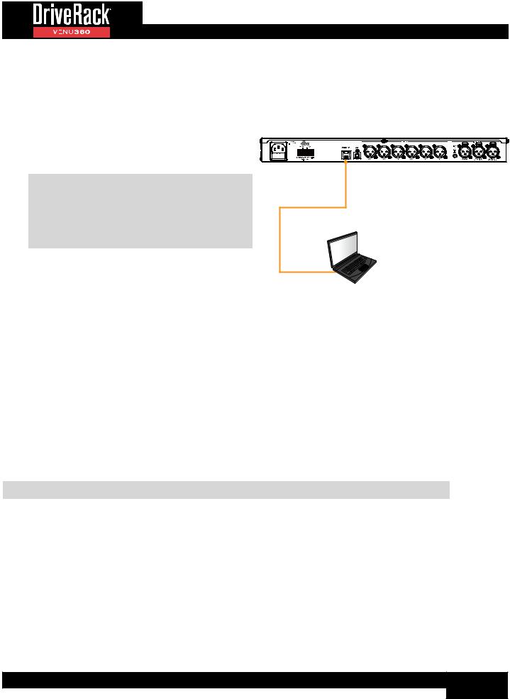
To connect directly to a computer:
1.Download and install the free DriveRack VENU360 control app on the iTunes Store®, Google Play™, or from www.dbxpro.com.
Direct Computer Connection
DriveRack VENU360
2. Connect a crossover CAT5, CAT5e, or CAT6 Ethernet cable (sold separately) to the Ethernet port on the VENU360.
NOTE: A crossover Ethernet cable MUST be used when connecting directly to the computer. A straight-through Ethernet cable will not work! See ‘Ethernet Cable Recommendations &
Diagrams’ on page 119 for further information on Ethernet cable types.
3.Connect the other end of the Ethernet cable to the Ethernet port on the computer.
4.Apply power to the VENU360 (ensure the amplifiers are powered off, see ‘Applying Power’ on page
4 for more information). Wait for the VENU360 to initialize.
Crossover Etherent Cable
Mac® or Windows®
Computer
5.To configure the VENU360’s network settings, press the UTILITY button then select the “Network” option.
If your computer is configured for Auto-IP addressing (i.e., the computer’s IP address is 169.254.xx.yy):
The default IP address and subnet mask in the VENU360 conform to the Auto-IP addressing standard (i.e., the IP address is 169.254.2.2 and the subnet mask is 255.255.0.0). To connect, simply turn DHCP “OFF” in the VENU360’s Utility > Network menu.
If your computer is configured with a static IP address that does not conform to the Auto-IP standard (i.e., something other than 169.254.xx.yy):
Configure the VENU360’s network settings to match your computer’s network ID and subnet mask settings, see ‘Networking Overview’ on page 114 for more information on these network settings.
6.To verify the VENU360’s IP address, press the UTILITY button then select the “SYSTEM INFO” option or press the SELECT wheel from Home mode and select the “SYSTEM INFO” home screen option.
TIP: For more information on networking, including troubleshooting tips, see ‘Networking’ on page 114.
5
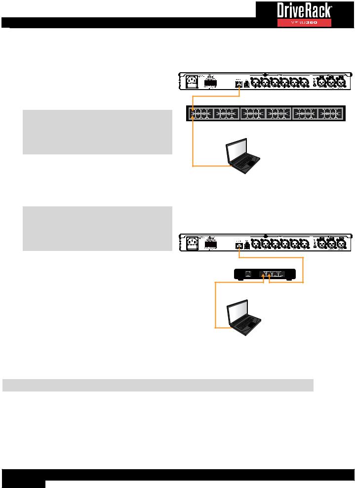
To connect to a wired network switch or router:
1.Download and install the free DriveRack VENU360 control app on the iTunes Store®, Google Play™, or from www.dbxpro.com.
2.Connect a straight-through CAT5, CAT5e or CAT6 Ethernet cable (sold separately) to the Ethernet port on the VENU360.
NOTE: A crossover Ethernet cable can also be used as long as the switch or router is capable of auto-sensing the type of Ethernet cable connected and reconfiguring itself accordingly (referred to as auto-MDI/MDIX sensing).
3.Connect the other end of the Ethernet cable to one of the switch or router’s LAN ports.
4.Connect your computer’s Ethernet port to one of the other LAN ports on the router or switch using a straight-through CAT5, CAT5e, or CAT6 cable.
NOTE: A crossover Ethernet cable can also be used as long as the switch or router is capable of auto-sensing the type of Ethernet cable connected and reconfiguring itself accordingly (referred to as auto-MDI/MDIX sensing).
Wired Network Switch Connection
DriveRack VENU360
Ethernet Switch
Mac® or Windows®
Computer
Wired Network Router Connection
DriveRack VENU360
5.Apply power to the VENU360 (ensure the amplifiers are powered off, see ‘Applying Power’ on page 4 for more information). Wait for the VENU360 to
initialize and give it time to negotiate with the network so it can be assigned an IP address – this can take a few minutes. You can ensure the VENU360 has been assigned an IP address by pressing the UTILITY button then selecting the “SYSTEM INFO” option or by pressing the SELECT wheel from Home mode and selecting the “SYSTEM INFO” home screen option.
6.If connecting using a static IP address, enter the VENU360 Utility menu by pressing the UTILITY button. Select the “NETWORK” option then configure the network settings to connect to your network.
Ethernet Router |
|
||
1 |
2 |
3 |
4 |
WAN |
|
LAN |
|
Mac® or Windows® |
|
|
|
Computer |
|
|
|
TIP: For more information on networking, including troubleshooting tips, see ‘Networking’ on page 114.
6

To connect to a Wi-Fi network router:
1.Download and install the free DriveRack VENU360 control app on the iTunes Store®, Google Play™, or from www.dbxpro.com.
2.Connect a straight-through CAT5, CAT5e, or CAT6 Ethernet cable (sold separately) to the Ethernet port on the VENU360.
NOTE: A crossover Ethernet cable can also be used as long as the switch or router is capable of auto-sensing the type of Ethernet cable connected and reconfiguring itself accordingly (referred to as auto-MDI/MDIX sensing).
3.Connect the other end of the Ethernet cable to one of the Wi-Fi router’s LAN ports.
4.Connect to the Wi-Fi network using your Wi-Fi equipped computer or device.
Wi-Fi Network Router Connection
DriveRack VENU360
|
|
|
|
|
|
|
|
|
|
|
|
|
|
|
|
|
|
|
|
|
|
|
|
|
|
|
|
|
|
|
|
|
|
|
|
|
|
|
|
|
|
|
|
|
|
|
|
|
|
|
|
|
|
|
|
|
|
|
|
|
|
|
|
|
|
|
|
|
|
|
|
|
|
|
|
|
|
|
|
|
|
|
|
|
|
|
|
|
|
|
|
|
|
|
|
|
|
|
|
|
|
|
|
|
|
|
|
|
|
|
|
|
|
|
|
|
|
|
|
|
|
|
|
|
|
|
|
|
|
|
|
|
|
|
|
|
|
|
|
|
|
|
|
|
|
|
|
|
|
|
|
|
|
1 |
2 |
3 |
4 |
|
|
|
|
||
|
|
|
|
|
|
|
|
|
|
|
|
|
|
|
|
|
|
|
|
|
|
|
|
|
|
|
|
|
WAN |
|
LAN |
|
|
|
|
|
|
|||
Wi-Fi Router
|
or |
Mac® or Windows® |
Android™ or iOS® |
Computer With Wi-Fi |
Tablet |
5.Apply power to the VENU360 (ensure the amplifiers are powered off, see ‘Applying Power’ on page 4 for more information). Wait for the VENU360 to initialize and give it time to negotiate with the network so it can be assigned an IP address – this can take a few minutes. You can ensure the VENU360 has been assigned an IP address by pressing the UTILITY button then selecting the “SYSTEM INFO” option or by pressing the SELECT wheel from Home mode and selecting the “SYSTEM INFO” home screen option.
6.If connecting using a static IP address, enter the VENU360 Utility menu by pressing the UTILITY button. Select the “NETWORK” option then configure the network settings to connect to your network.
TIP: For more information on networking, including troubleshooting tips, see ‘Networking’ on page 114.
7
User Interface & Connectors
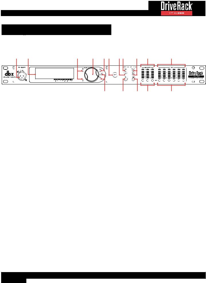
Front Panel
|
1 |
2 |
3 |
4 |
5 6 |
7 8 |
9 |
10 |
11 |
1. |
RTA MIC INPUT |
|
|
12 |
13 |
14 |
15 |
16 |
|
|
|
|
|
|
|
|
|||
Connect the dbx RTA-M measurement microphone (sold separately) to this balanced XLR input jack for easy calibration of the sound system using the built-in Wizards or for use with the RTA. This jack supplies +48V phantom power.
2. LCD Display
This LED backlit LCD display provides the visual feedback required for operating the VENU360 processor from the front panel. The LCD’s backlight intensity and contrast can be adjusted in the Utility menu, see ‘Utility Menu’ on page 92 for more information.
3. UP/DOWN Buttons
Pressing the UP button will select the on-screen item above the current selection. Pressing the DOWN button will select the on-screen item below the current selection. When in Home mode, pressing these buttons will toggle between the available home screens, see ‘The Home Screens’ on page 14 for more information.
4. SELECT Wheel
This rotary encoder is used for scrolling menus, selecting on-screen options and parameters, and editing selected on-screen options and parameters. Some functions are performed by turning the SELECT wheel and others are performed by pressing the SELECT wheel. When in Home mode, pressing the SELECT wheel will bring up a menu where you can select from the available home screens, see ‘The Home Screens’ on page 14 for more information.
5. BACK Button
Pressing this button will navigate back one level in the current menu hierarchy. Pressing this button repeatedly will navigate back to the home screen.
6. WIZARD Button
Pressing this button enters the Wizard menu. When in the Wizards, pressing and holding the WIZARD button for ~2 seconds will abort the Wizard and return to the main Wizard menu. For more information on the Wizards, see ‘Using The Wizards (Wizard Mode)’ on page 17.
7. CONFIG (CONFIGURATION) Button
Pressing this button will enter Configuration mode, where manual changes to the configuration can be made. For more information on using Configuration mode, see ‘Using Configuration Mode’ on page 24.
8
8. EDIT Button
Pressing this button will enter Edit mode. Once in Edit mode, the UP/DOWN buttons and SELECT wheel can be used to select the desired on-screen processing module for editing or copying and pasting. Pressing and holding this button when in a processing module’s edit menu will jump between the selected column’s processing edit menus, for fast in-menu navigation of like processing modules. For more information on using Edit mode, see ‘Editing Processing Module Parameters (Edit Mode)’ on page 43.
9. PRESET RECALL & STORE Buttons
These buttons are used to store and recall presets. For more information on managing presets, see ‘Managing Presets’ on page 45.
10. MIX/ROUTE Meters & CLIP Indicators
These 6-segment LED meters display the input signal level strength and available headroom, and range from SIG (signal present) to 0 (dBFS). These meters monitor the signal level at the 1/2/3 bus points immediately after the input Mixers/Routers (see ‘DSP Block Diagram’ on page 118 to see a diagram of the signal flow). They will light when the signal level is greater than or equal to the values shown in the table to the right.
Input |
|
+14 dBu |
+20 dBu |
+24 dBu |
+28 dBu |
|
dBFS |
Analog Gain |
Analog Gain |
Analog Gain |
Analog Gain |
||
LEDs |
||||||
|
Setting |
Setting |
Setting |
Setting |
||
|
|
|||||
0 |
-0.1 |
+14.1 dBu |
+20.0 dBu |
+24.2 dBu |
+28.2 dBu |
|
|
|
|
|
|
|
|
3 |
-3 |
+12.2 dBu |
+18.2 dBu |
+22.2 dBu |
+26.3 dBu |
|
|
|
|
|
|
|
|
10 |
-10 |
+5.2 dBu |
+11.2 dBu |
+15.3 dBu |
+19.3 dBu |
|
|
|
|
|
|
|
|
15 |
-20 |
-4.8 dBu |
+1.2 dBu |
+5.3 dBu |
+9.3 dBu |
|
|
|
|
|
|
|
|
20 |
-30 |
-14.8 dBu |
-8.8 dBu |
-4.7 dBu |
-0.7 dBu |
|
|
|
|
|
|
|
|
SIG |
-48 |
-32.8 dBu |
-26.8 dBu |
-22.7 dBu |
-18.7 dBu |
|
|
|
|
|
|
|
The LEDs located at the top of the Mix/Route meters are clip indicators. When these LEDs light, it indicates that the VENU360’s inputs are being overdriven – either at the physical XLR input or in the input Mixers/Routers. These LEDs feature a peak hold function, so they will remain lit for a short period of time after the signal level drops back below the clip point. The dbx Type IV™ conversion system built into the VENU360 will clamp down on excessively loud input signals to prevent the A/D converters from clipping. If these LEDs light consistently, check to see if any dramatic gains are being applied in the VENU360’s input Routers/Mixers. If input Router/Mixer gains are not causing the issue, you may need to change the analog input clip level settings in the Utility menu (see ‘Utility Menu’ on page 92 for more information) or lower the output signal level from the sending device.
11. OUTPUT Meters & LIMITER THRESHOLD Indicators
These 6-segment LED meters display the output signal level strength and available headroom and range from SIG (signal present) to 0 (dBFS). These meters monitor the signal level post the output processing and MUTE buttons and before the D/A converters. They will light when the signal level is greater than or equal to the values shown in the following table.
Input |
dBFS |
+4 dBu Analog |
+8 dBu |
+12 dBu |
+14 dBu |
+17 dBu |
+20 dBu |
+22 dBu |
|
Analog Gain |
Analog Gain |
Analog Gain |
Analog Gain |
Analog Gain |
Analog Gain |
||||
LEDs |
Gain Setting |
||||||||
|
Setting |
Setting |
Setting |
Setting |
Setting |
Setting |
|||
|
|
|
|||||||
0 |
-0.1 |
+4.5 dBu |
+8.6 dBu |
+12.4 dBu |
+14.3 dBu |
+17.2 dBu |
+19.8 dBu |
+22.1 dBu |
|
|
|
|
|
|
|
|
|
|
|
3 |
-3 |
+3.1 dBu |
+7.2 dBu |
+11.0 dBu |
+12.9 dBu |
+15.8 dBu |
+18.4 dBu |
+20.8 dBu |
|
|
|
|
|
|
|
|
|
|
|
10 |
-10 |
-3.8 dBu |
+0.3 dBu |
+4.0 dBu |
+5.9 dBu |
+8.9 dBu |
+11.4 dBu |
+13.8 dBu |
|
|
|
|
|
|
|
|
|
|
|
15 |
-20 |
-13.8 dBu |
-9.8 dBu |
-6.0 dBu |
-4.1 dBu |
-1.1 dBu |
+1.4 dBu |
+3.8 dBu |
|
|
|
|
|
|
|
|
|
|
|
20 |
-30 |
-23.8 dBu |
-19.8 dBu |
-16.0 dBu |
-14.1 dBu |
-11.1 dBu |
-8.6 dBu |
-6.2 dBu |
|
|
|
|
|
|
|
|
|
|
|
SIG |
-48 |
-41.8 dBu |
-37.8 dBu |
-34.0 dBu |
-32.1 dBu |
-29.1 dBu |
-26.6 dBu |
-24.2 dBu |
|
|
|
|
|
|
|
|
|
|
9

The multi-colored threshold LEDs located at the top of the output meters indicate output limiter activity within the corresponding output channels. The three colored states are:
•Green
Indicates the signal level is under threshold and no limiting is occurring.
•Yellow
Indicates the signal level is in the OverEasy® region and some minor limiting is occurring. This state is only active when the Limiter’s “OVER EASY” setting is turned on.
•Red
Indicates the signal level has exceeded the Limiter’s threshold and full limiting is occurring.
12.COPY/PASTE Buttons
These buttons allow you to copy and paste various parameter settings and processor module types within the VENU360. See ‘Copying/Pasting Processing Module Settings’ on page 44, ‘Configuring Mixers/Routers’ on page 28, and ‘Configuring Processing Module Insert Types’ on page 30 for more information on how to use the
copy/paste functions.
13. RTA Button
Pressing this button will enter the RTA module. See ‘RTA’ on page 89 for more information on the RTA.
14. UTILITY Button
Pressing this button enters the Utility menu, where you can get information about the VENU360’s firmware and network settings and configure global system settings which dictate how the VENU360 operates. See ‘Utility Menu’ on page 92 for information on the options and parameters available in the Utility menu.
15. MIX/ROUTE MUTE Buttons
Pressing each of these buttons will enable/disable the “MASTER MUTE” parameter inside each corresponding input Mixer/Router module. When enabled, the signal will be muted prior to the front-panel meters (see ‘DSP Block Diagram’ on page 118 to see a diagram of the signal flow). The state of these mutes are stored with presets.
16. OUTPUT MUTE Buttons
Pressing each of these buttons will mute the corresponding output channel prior to the limiters and output meters (see ‘DSP Block Diagram’ on page 118 to see a diagram of the signal flow). The state of these mutes are global and are not stored to presets. However, by default, the state of these buttons will be retained after a power cycle.
The MUTES POWERUP function, available in the Utility menu, lets you configure the VENU360 to always power on with all outputs muted. See ‘Mutes Powerup’ under ‘Utility Menu’ on page 92 for more information on this feature.
You can also press and hold any MUTE button upon power up to force the VENU360 to initialize with all outputs muted, see ‘Initialize With Mutes On’ on page 96 for more information on this feature.
NOTE: All output MUTE buttons are automatically enabled when recalling a preset, applying configuration changes, and after running the Setup Wizard. This is a safety feature. When you’re ready to audition or use the system, simply unmute the output channels.
10
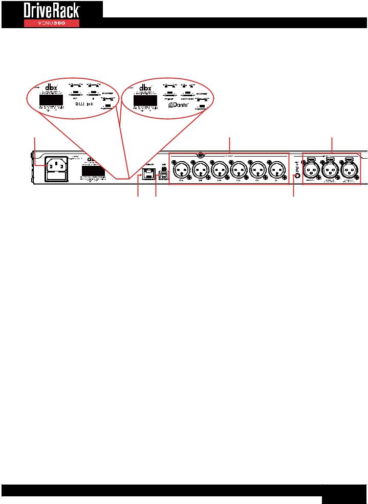
Rear Panel
7 |
|
|
|
|
|
|
|
|
|
|
|
|
|
|
|
|
|
|
|
|
|
|
|
|
|
8 |
|
|
|
|
|
|
|
|
|
|
|
|
|
|
|
|
|
|
|
|
|
|
|||||||
|
|
|
|
|
|
|
|
|
|
|
|
|
|
|
|
|
|
|
|
|
|
|
|
|
|
|
|
|
|
|
|
|
|
|
|
|
|
|
|
|
|
|
|
|
|
|
|
|
|
|
|
|
|
|
|
|
|
|
|
|
|
|
|
|
|
|
|
|
|
|
|
|
|
|
|
|
|
|
|
|
|
|
|
|
|
|
|
|
|
|
|
|
|
|
|
|
|
|
|
|
|
|
|
|
|
|
|
|
|
|
|
|
|
|
|
|
|
|
|
|
|
|
|
|
|
|
|
|
|
|
|
|
|
|
|
|
|
|
|
|
|
|
|
|
|
|
|
|
|
|
|
|
|
|
|
|
|
|
|
|
|
|
|
|
|
|
|
|
|
|
|
|
|
|
|
|
|
|
|
|
|
|
|
|
|
|
|
|
|
|
|
|
|
|
|
|
|
|
|
|
|
|
|
|
|
|
|
|
|
|
|
|
|
|
|
|
|
|
|
|
|
|
|
|
|
|
|
|
|
|
|
|
|
|
|
|
|
|
|
|
|
|
|
|
|
|
|
|
|
|
|
|
|
|
|
|
|
|
|
|
|
|
|
|
|
|
|
|
|
|
|
|
|
|
|
|
|
|
|
|
|
|
|
|
|
|
|
|
|
|
|
|
|
|
|
|
|
|
|
|
|
|
|
|
|
|
|
|
|
|
|
|
|
|
|
|
|
|
|
|
|
|
|
|
|
|
|
|
|
|
|
|
|
|
|
|
|
|
|
|
|
|
|
|
|
|
|
|
|
|
|
|
|
|
|
|
|
|
|
|
|
|
|
|
|
|
|
|
|
|
|
|
|
|
|
|
|
|
|
|
|
|
|
|
|
|
|
|
|
|
|
|
|
|
|
|
|
|
|
|
|
|
|
|
|
|
|
|
|
|
|
|
|
|
|
|
|
|
|
|
|
|
|
|
|
|
|
|
|
|
|
|
|
|
|
|
|
|
|
|
|
|
|
|
|
|
|
|
|
|
|
|
|
|
|
|
|
|
|
|
|
|
|
|
|
|
|
|
|
|
|
|
|
|
|
|
|
|
|
|
|
|
|
|
|
|
|
|
|
|
|
|
|
|
|
|
|
|
|
|
|
|
|
|
|
|
|
|
|
|
|
|
|
|
|
|
|
|
|
|
|
|
|
|
|
|
|
|
|
|
|
|
|
|
|
|
|
|
|
|
|
|
|
|
|
|
|
|
|
|
|
|
|
|
|
|
|
|
|
|
|
|
|
|
|
|
|
|
|
|
|
|
|
|
|
|
|
|
|
|
|
|
|
|
|
|
|
|
|
|
|
|
|
|
|
|
|
|
|
|
|
|
|
|
|
|
|
|
|
|
|
|
|
|
|
1 |
|
4 |
6 |
2 |
3 |
|
5 |
1. AC Power Inlet
Connect the included IEC power cable to this power inlet. The power supply in the VENU360 is a switch-mode power supply and can be operated using a mains voltage of 100-240V, 50Hz/60Hz.
2. Ethernet Port
This RJ-45 connector allows the VENU360 to be connected to a local network and controlled using the free DriveRack VENU360 control app. VENU360 firmware updates can also be performed over this port using the free VENU360 control app. See ‘Firmware Updates’ on page 117 for more information on firmware updates.
3. USB Port
This USB port provides another way of updating the VENU360’s firmware. See ‘Firmware Updates’ on page 117 for more information on firmware updates.
4. XLR Outputs
These six electronically balanced XLR analog outputs correspond to the output processing chains in the VENU360. The crossovers and output processing chains can be configured for everything from full range up to mono 6-way configurations. Output channel processing modules can be linked with adjacent channels, providing outstanding configuration flexibility.
The maximum analog output clip levels can be adjusted for these outputs in the Utility menu. This can help optimize the analog signal-to-noise performance and gain structure between the VENU360 and amplifiers or powered speakers. See ‘ANALOG INPUT/OUTPUT CLIP LEVELS’ on page 94 for more information on the analog output clip
levels.
If using a VENU360-B or VENU360-D model, the signal sent to each of the XLR outputs will be mirrored to the 6 assigned BLU link or Dante output channels. VENU360-B BLU link output channels can be assigned in the Utility > BLU link menu (see ‘Utility Menu’ on page 92) or using the BLU link Setup Wizard (see ‘Using The Wizards (Wizard Mode)’ on page 17). Dante output channles in the VENU360-D are assigned using Audinate®’s Dante Controller software.
11

5. PIN1 (Ground) Lift Switch
This switch lifts the pin 1 chassis ground on all XLR input connectors. In most applications, this switch should be left in the out (disabled) position. If hum becomes an issue and is caused from a ground loop between your mixer and VENU360, try engaging this switch.
6. XLR Inputs
Connect your mixer to these electronically balanced XLR connectors. The first two XLR connectors can be independently configured for analog or AES digital operation in the Utility menu (see ‘Utility Menu’ on page 92) or by running the Setup Wizard (see ‘Using The Wizards (Wizard Mode)’ on page 17). Note that 110 ohm balanced cables should be used for AES connections. The third XLR connector is a fixed analog connection.
When using these inputs with analog connections, the input sensitivity can be set in the Utility menu. This can help optimize the analog signal-to-noise performance and gain structure between the mixer and VENU360. See ‘ANALOG INPUT/OUTPUT CLIP LEVELS on page 94 for more information on adjusting analog input clip levels.
7. BLU link Ports
Available only on the VENU360-B model, these two RJ-45 ports can be used to connect to other BLU link-enabled devices for transmission and receival of high-resolution digital audio over Ethernet cable. The VENU360-B supports 8 BLU link input channels x 6 BLU link output channels.
BLU link is a point-to-point digital audio bus with 256 audio channels at a 48 kHz sample rate or 128 audio channels at a 96 kHz sample rate. The physical connections are made with CAT5e or CAT6 cables. The devices are connected in a daisy chain fashion continuing with the OUT port of one device connected to the IN port of the next device.
Redundancy can be provided by completing the loop and connecting the OUT port from the last device to the IN port of the first device in the chain. Do not connect BLU link ports to a hub, network switch, or router – BLU link audio will not pass through such devices. All devices connected in the BLU link ring/chain must be configured for the same audio sample rate.
See ‘Application 8: BLU Link Application (VENU360-B)’ on page 106 for more information on connecting to the the BLU link ports.
8. Dante™ Ports
Available only on the VENU360-D model, these two RJ-45 ports can be used to connect to other Dante-enabled devices for transmission and receival of high-resolution digital audio over Ethernet cable. The VENU360-D supports 8 Dante input channels x 6 Dante output channels.
Dante is a licensed technology from Audinate®. It uses standard Internet Protocols over a 100Mb or Gigabit network and is capable of transporting professional-quality, low-latency audio. Dante runs on inexpensive off-the-shelf computer networking hardware and does not require dedicated network infrastructure; Ethernet switches transmit Dante digital media streams alongside ordinary data traffic. The physical Dante connections must be made using CAT5e or CAT6 cables when using a Gigabit network (CAT5 may be used for purely 100Mbps networks).
The VENU360-D offers a Primary and a Secondary Dante port; Dante audio traffic is duplicated to both of these ports. The Secondary port can be connected to the network switch for redundant operation in the event the Primary cable connection is compromised.
See ‘Application 9: Dante Application (VENU360-D)’ on page 109 for more information on connecting to the Dante ports.
12
Getting Started
Operating Modes Explained
Home Mode
This is the default operating mode. It is the mode the VENU360 enters when it initially boots and is the mode which displays the home screen. There are various home screens to choose from when in Home mode. See ‘The Home Screens’ on page 14 for more information on each of the available home screens and how to access them.
You can get back to Home mode from any menu by repeatedly pressing the BACK button. How many times you must press the BACK button to return to Home mode is determined by how deeply you have navigated in the current menu.
Wizard Mode
This mode is entered by pressing the WIZARD button and walks you through the system configuration and optimization process with step-by-step instructions. See ‘Using The Wizards (Wizard Mode)’ on page 17 for more information on using the Wizards.
Configuration Mode
Configuration mode is entered by pressing the CONFIG button. This mode is used to make manual configuration changes to a preset and to create more-advanced configurations not possible with the Setup Wizard alone.
When in Configuration mode, the ‘Configuration Mode’ icon will appear in the upper left-hand corner of the LCD display and the SELECT wheel and UP/
DOWN buttons can be used to navigate the on-screen configuration map to select a module to configure. As each module is selected, the title at the top of the screen will display descriptive information about it. The icon in the upper-right corner of the display indicates the input/output channels affected by the selected module. Once the desired module is selected, pressing the SELECT wheel will present the options available for configuration. See ‘Using Configuration Mode’ on page 24 for more information on using Configuration mode.
Edit Mode
Edit mode is entered by pressing the EDIT button. This mode is used to edit processing module parameters (e.g., Compressor parameters, Crossover parameters, etc.).
When in Edit mode, the ‘Edit Mode’ icon will appear in the upper left-hand corner of the LCD display and, just as in Configuration mode, the SELECT
wheel and UP/DOWN buttons can be used to navigate the on-screen configuration map to select a module to edit. As each module is selected, the title at the top of the screen will display descriptive information about it. The icon in the upper-right corner of the display indicates the input/output channels affected by the selected module. Once the desired module is selected, pressing the SELECT wheel will enter its menu, where its parameters can be edited. See ‘Editing Processing Module Parameters (Edit Mode)’ on page 43 for more information on using Edit mode.
13

The Home Screens
The home screen is the first screen which appears in the LCD display after the VENU360 fully initializes (this mode is referred to as “Home” mode). There are several home screens to choose from, providing the instant visual feedback you need, when you need it. All home screens will display information about the currently loaded preset and clock sync status, as shown in the below callout.
Preset # / Type Preset Name |
Clock Source / Sample Rate |
||||||||
|
|
|
|
|
|
|
|
|
|
|
|
|
|
|
|
|
|
|
|
|
|
|
|
|
|
|
|
|
|
If the preset name is longer than can be displayed on-screen, turning the SELECT wheel allows you to scroll the preset name and view the additional characters.
Home screens can be accessed by pressing the SELECT wheel and selecting the desired home screen from the pop-up menu or pressing the UP/DOWN buttons. Following is a description of each available home screen.
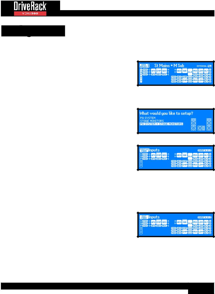
Configuration Map Home Screen
This is the default home screen. This screen shows the configuration and signal flow of the currently loaded preset. The left of the screen indicates the input processing configuration. The right of the screen indicates the output processing configuration. The blocks represent the processing modules. The brackets located at the top of some columns indicate configurable processing insert slots.
Dynamics Gain Home Screen
This home screen shows a global view of all gain changes applied by any configured dynamics processors (i.e., Compressors, Limiters, AGCs, and Noise Gates). Any insert slots configured as anything other than
a dynamics processor will be represented by a bubble indicating the processor type with a line displayed where a gain meter would otherwise reside.
Dynamics Threshold Home Screen
This home screen shows a global view of the threshold indicators for all configured dynamics processors (i.e., Compressors, Limiters,
AGCs, and Noise Gates). Any insert slots configured as anything other than a dynamics processor will be represented by a bubble indicating the processor type with a line displayed where a threshold indicator would otherwise reside. For information on the meaning of each of the threshold indicators shown in this home screen, see the Compressor, Limiter, AGC, and Noise Gate Module sections under ‘Processing Modules & Parameters’ on page 58.
Configuration Map Home Screen
Dynamics Gain Home Screen
Dynamics Threshold Home Screen
14
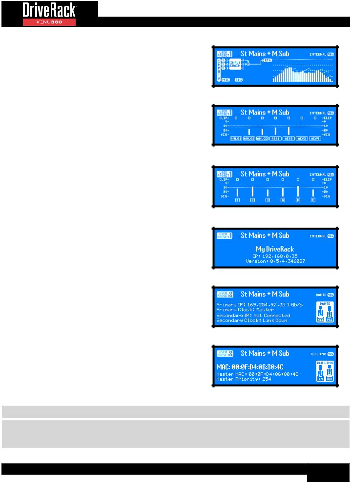
RTA Home Screen
This home screen provides quick access to the Real-Time Analyzer. The graphic to the left of the RTA displays the signal source feeding the RTA, which is set with the RTA SOURCE parameter in the RTA menu. See ‘RTA’ on page 89 for more information on the RTA menu and parameters.
Input Meters Home Screen
This home screen displays the signal level and clip indicators for all VENU360 inputs.
Bus Meters Home Screen
This home screen displays metering for all bus points in the input signal path (i.e., 1, 2, 3, A, B, and C). The 1/2/3 bus points are pre the input signal processing chains. The A/B/C bus points are post the input processing chains. See ‘Configuring Mixers/Routers’ on page
28 and ‘DSP Block Diagram’ on page 118 for more information on these bus points.
System Info Home Screen
This home screen shows the name of the VENU360 device, currently installed firmware version, and current IP status/address.
Dante Info Home Screen
This home screen is available in the VENU360-D model and shows Dante connection information at a glance. The port connection icons on the right of the screen will show whether each Dante port is connected or disconnected. Additional Dante information can be found in the Utility menu, see ‘DANTE’ on page 93 for more information.
BLU Link Info Home Screen
This home screen is available in the VENU360-B model and shows BLU link connection information at a glance. The port connection icons on the right of the screen will show whether each BLU link port is connected, disconnected, or connected with an issue (an “X” will appear in the connection icon if there is a connection issue). Additional BLU link information can be found in the Utility menu, see ’BLU LINK’ on page 92 for more information.
RTA Home Screen
Input Meters Home Screen
Bus Meters Home Screen
System Info Home Screen
Dante Info Home Screen
BLU Link Info Home Screen
NOTE: After a power cycle, the VENU360 will return to the home screen selected before the unit was powered down.
NOTE: The HOME TIME OUT feature in the Utility menu will determine if the VENU360 will return to the home screen after a period of inactivity and how long it will wait before timing out. See ‘HOME SCREEN TIME OUT’ on page 95 for further information on the HOME TIME OUT feature.
15
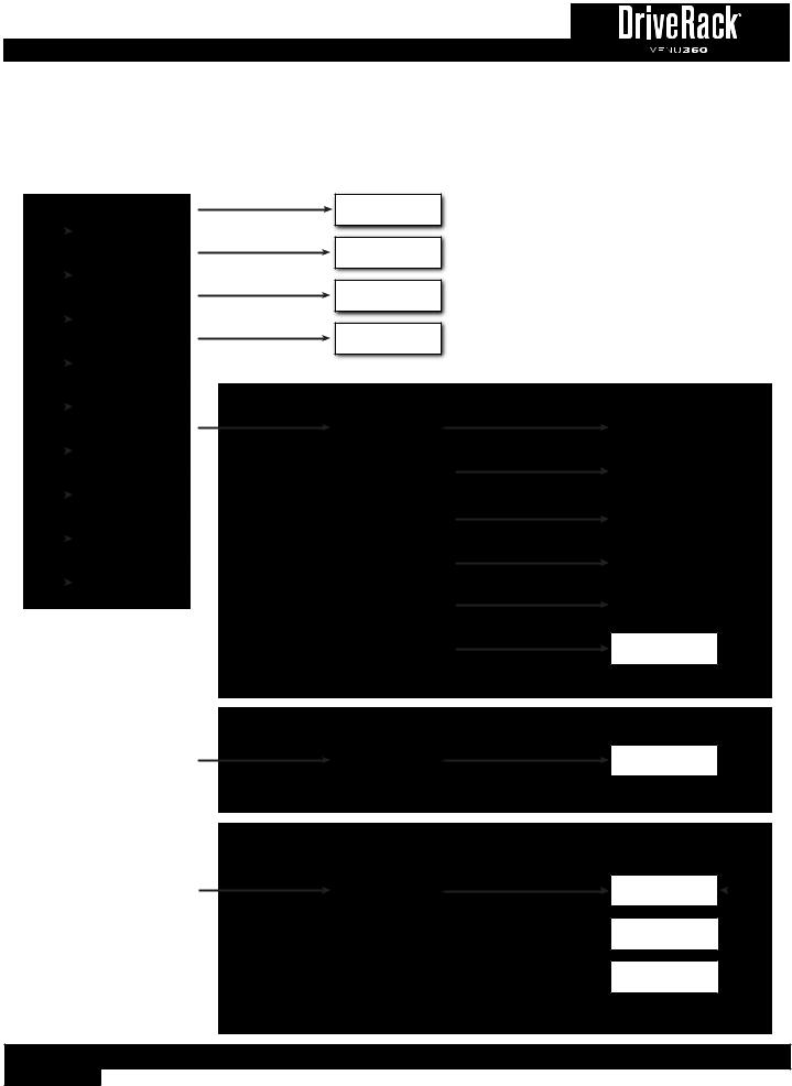
Menu Navigation
The VENU360 menu navigation is laid out as shown in the below diagram.
HOME MODE
|
|
|
|
|
|
|
|
|
|
Con guration Map |
|
|
|
|
|
Home Screen |
|
|
|
|
|
|
|
|
|
|
|
|
|
|
|
|
|
Dynamics Gain |
|
|
|
|
|
Home Screen |
|
|
|
|
|
|
|
|
|
|
|
|
|
Buttons |
|
|
|
Dynamics Threshold |
|
|
|
|
Home Screen |
|
|
|
|
|
|
|
|
|
|
|
|
|
|
/DOWNUP |
|
|
|
RTA |
|
|
|
|
|
Home Screen |
|
|
|
|
|
|
|
|
|
|
|
|
|
or |
|
|
|
Input Meters |
|
|
|
|
Home Screen |
|
|
Wheel |
|
|
|
|
|
|
|
|
|
|
|
|
|
|
|
|
|
PressSELECT |
|
|
|
System Info |
|
|
|
|
|
Bus Meters |
|
|
|
|
|
Home Screen |
|
|
|
|
|
|
|
|
|
|
|
Home Screen |
|
|
|
|
|
||
|
|
|
|
|
|
|
|
|
|
|
|
|
|
|
|
BLU Link Info Home |
|
|
|
|
|
Screen (VENU360-B) |
|
|
|
|
|
|
|
|
|
|
|
|
|
|
|
|
|
Dante Info Home |
|
|
|
|
|
Screen (VENU360-D) |
|
|
|
|
|
|
|
|
|
|
|
|
|
Menu Navigation Tree Diagram
Press RTA Button
Press RECALL Button
Press STORE Button
Press UTILITY Button
RTA Menu
Preset Recall Menu
Preset Store Menu
Utility Menu
WIZARD MODE
Press WIZARD Button |
Wizard Menu |
|
Turn SELECT Wheel, Press SELECT |
|
|
Turn SELECT Wheel, Press SELECT |
|
|
|
|
|
|
|
|
|
|
|
|
Turn SELECT Wheel, Press SELECT |
|
|
|
Turn SELECT Wheel, Press SELECT |
|
|
|
Turn SELECT Wheel, Press SELECT |
|
|
|
Turn SELECT Wheel, Press SELECT |
|
|
|
|
CONFIGURATION MODE
Press CONFIG Button |
|
Turn SELECT Wheel, |
Con guration Mode |
Press UP/DOWN, Press SELECT |
|
|
|
|
|
|
|
EDIT MODE
|
|
Turn SELECT Wheel, |
Press EDIT Button |
Edit Mode |
Press UP/DOWN, Press SELECT |
|
|
|
|
|
|
|
|
|
Button |
|
|
|
|
|
Run All Wizards |
|
WIZARDAbort To |
|
|
|
|
|
|
|
|
|
BLU Link Wizard |
|
& Press & Wizard |
|
(VENU360-B) |
|
|
|
|
|
|
|
|
|
|
|
Run System |
|
Hold Return |
|
Setup Wizard |
|
|
|
|
|
|
|
|
|
To |
|
|
|
|
|
Run AutoEQ/ |
|
The |
|
Level Assist Wizard |
|
Wizard |
|
|
|
|
|
|
|
|
|
|
|
|
|
Run AFS Wizard |
|
MenuMain |
|
|
|
|
|
|
|
|
Wizard Options
Selected Module’s
Edit Menu
Selected Module’s
Edit Menu
Edit Menu For Next
Module Below In Map
Etc...
HoldNext& PressTo NavigateEDITTo Button
Column Map gCon In Below Menu Module’s

16
Configuring The VENU360
There are two ways to configure the VENU360: using the Setup Wizard or using Configuration mode. For some applications, both methods may be required.
The easiest way to configure the VENU360 is to use the built-in Setup Wizard. This works well for configuring most systems, including stage monitors and PA systems with crossover configurations from full range up to mono 4-way (3-way main speakers with subs). It also works well for initially configuring the VENU360 for delay fill and zone applications. However, some applications will require further customization of the configuration using Configuration mode. This section of the manual describes how to use the Wizard and Configuration modes in more detail.
Using The Wizards (Wizard Mode)
The VENU360 Wizards walk you through the configuration and optimization process with simple, step-by-step instructions, making it easy to setup the VENU360 for your application. Using the optional dbx RTA-M measurement microphone, the Wizards can optimize your sound system by helping adjust your system level balance and analyzing your room and applying accurate room EQ – in a fraction of the time it would take to manually analyze and calibrate the system!
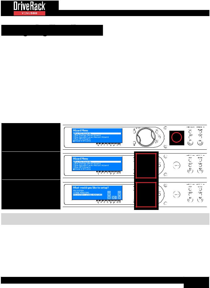
To use the Wizards to configure and optimize a new system:
1. Press the WIZARD button.
2. Select the “RUN ALL WIZARDS” option using the SELECT wheel.
3. Follow the on-screen instructions. Turn the SELECT wheel to edit on-screen selections and press the SELECT wheel to confirm on-screen selections and advance through the Wizards.
TIP: Pressing and holding the WIZARD button for ~2 seconds at any time during the Wizard procedure will abort the current Wizard and return to the main Wizard menu.
Following is a description of each of the available options in the VENU360’s Wizard menu.
Run All Wizards
Select this option to run through all Wizards in succession. Note that there are points where you do have the option to opt out of the AutoEQ and AFS Wizards if necessary.
Run BLU link Setup Wizard (VENU360-B Only)
Running the BLU link Setup Wizard walks you through the process of configuring a VENU360-B for connection with other BLU link-enabled devices, this includes BLU link sample rate, input channel assignments and names, and output channel
17
assignments. All of these settings can also be edited manually in the Utility > BLU link menu. See ‘BLU LINK’ on page 92 for further information on the BLU link menu.
Run System Setup Wizard
This Wizard allows you to select your speaker and amplifier models from a tuning list and automatically sets the crossover, output parametric EQ, driver alignment delay, polarity, analog output clip levels, and limiter settings if your speaker and amp models are listed. If your components are not listed, check the cloud using the VENU360 control app to see if they’ve been added. If they haven’t been added, select the “Not Listed??” option – default settings will still be set to get you started. This Wizard will also configure the XLR inputs for analog or AES operation and the master clock source.
TIP: If re-configuring a preset which was initially configured using the Setup Wizard, you will receive a prompt asking if you would like to, “Start from default settings?”. Select the “YES” option to default the Setup Wizard settings and start from scratch. Selecting the “NO” option will present the Setup Wizard with the options selected when initially running the Setup Wizard to create the preset. Note that if you’re updating a preset by re-running the Setup Wizard – for example, if you’ve upgraded amps or speakers – any changes that were made to the preset in Configuration mode or to processing module settings will be lost! Therefore, it’s recommended that you first copy your stored preset to another memory location before re-running the Setup Wizard. This way you can use the original preset for reference and copy/paste processing module settings from the original preset to the new preset.
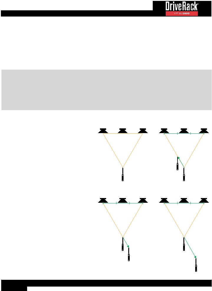
Run AutoEQ/Level Assist Wizard
When used with the optional dbx RTA-M measurement microphone, these Wizards help you balance speaker levels and automatically equalize the system to the current room environment.
The diagrams to the right show the recommended Level Assist and AutoEQ RTA-M mic positions. When running AutoEQ, you will be prompted to select how many
mic positions you would like AutoEQ to analyze – the selections are 2, 3, or 4.
The Level Assist and AutoEQ mic position 1 measurements should be taken with the microphone placed equidistant from the speakers, so that the three components form an equilateral triangle, as shown in the Level Assist/AutoEQ Mic Position 1 diagram. If analyzing a mono speaker, place the mic in the position that makes the most sense. For example, if analyzing a stage monitor, place the mic in the location where the artist monitoring the signal will be.
Each time you move the RTA-M mic position it should move approximately 1/3rd the distance the speakers are apart from the initial “RTA-M Mic Placement 1 Reference”, as shown in the AutoEQ Mic Position 2-3 diagrams. If analyzing a mono speaker, move the mic by around 1-2’ in the same direction shown in the diagrams.
Mic position 4 is the exception as it should be placed 2/3rds the distance from the RTA-M Mic Placement 1 Reference. If analyzing a mono speaker, move the mic by a distance of around 3’ in the same direction shown in the diagram.
Level Assist/AutoEQ Mic Position 1
Left Speaker |
Center/Mono Speaker Right Speaker |
Speakers & Mic Form an
Equilateral Triangle
RTA-M Mic
Placement 1
AutoEQ Mic Position 3 (Optional)
Left Speaker |
Center/Mono Speaker Right Speaker |
/rd /rd /rd
/
rd
RTA-M Mic
Placement 1
Reference
RTA-M Mic
Placement 3
AutoEQ Mic Position 2
Left Speaker Center/Mono Speaker Right Speaker
/rd /rd /rd
/
rd
RTA-M Mic
Placement 2
RTA-M Mic
Placement 1
Reference
AutoEQ Mic Position 4 (Optional)
Left Speaker Center/Mono Speaker Right Speaker
/rd /rd /rd
|
|
|
|
/ |
|
RTA-M Mic |
|
|
|
|
|
Placement 1 |
|
rds |
Reference |
|
|
RTA-M Mic
Placement 4
18
For example, if your speakers were 20 feet apart, you would move the microphone approximately 7’ (20 * (1/3) = 6.6) from the RTA-M Mic Placement 1 Reference for mic positions 2-3 and approximately 14’ from the RTA-M Mic Placement 1 Reference for mic position 4. However, as a general rule of thumb and for the sake of simplicity, a distance of 5’ should work well for
PA systems in most venues (around 1-3’ for stage monitors). If the recommended placement of the mic in positions 2-4 are not possible, just place the mic in a position that differs from the other measurement positions to achieve a more accurate averaged response.
When a live sound system’s frequency response is flattened, it can sound a bit thin on the low-end. When running AutoEQ, you will be given an option to select the desired AutoEQ “TARGET CURVE”. Select the RECOMMENDED PA CURVE option (this is the default setting) to allow AutoEQ to automatically boost the low-end and prevent it from sounding thin. Select the FLAT option if you do want the system to be tuned flat when running the AutoEQ Wizard. Select the REFLECTIVE ROOM option to automatically attenuate higher frequencies when operating a sound system in a room with excessive acoustic reflections.
Run AFS Wizard
This Wizard walks you through the process of ringing out the system to provide higher system gain before feedback. This is accomplished by pushing your system into feedback so AFS can detect the frequencies that are prone to feedback and notch them using Fixed filters. When the AFS Wizard is complete, it will automatically enable the Live filters, for automated protection during system use. To use the AFS Wizard, simply set up all the microphones, perform a sound check, set up a rough mix for all microphones which will be used during the performance, then follow the on-screen instructions.
Wizard Options
The available options in this menu are:
•Level Assist Auto Trim [ON, OFF]
When this option is turned on, Level Assist will automatically make fine level adjustments under the hood for any system level mismatches which are 3 dB or less. When this option is turned off, no automatic level adjustments will be made by Level Assist and all system level mismatches will need to be adjusted using the amplifier attenuators until they are within a 1 dB tolerance.
NOTE: Level adjustments made by the LEVEL ASSIST AUTO TRIM function cannot be seen or edited. To clear them you must turn the LEVEL ASSIST AUTO TRIM function off then re-run Level Assist in the Wizard menu.
•Mic Response [dbx RTA-M, FLAT]
When the dbx RTA-M option is selected, AutoEQ will automatically compensate for the frequency response of the dbx RTA-M microphone, providing more accurate AutoEQ results. Select the FLAT option if using a measurement microphone other than the dbx RTA-M.
•Setup Auto Preset Naming [ON, OFF]
When this option is on, the VENU360 will automatically name presets based on the speaker selections made in the Setup Wizard. Note that the automatically generated preset name can still be edited when storing the preset if desired.
19
Configuring Inputs, Master Clock Source, & SRC
The VENU360 allows you to select either the internal crystal oscillator or one of the AES inputs for clock master. When using the VENU360-B/VENU360-D models and connecting to a BLU link ring or Dante network, master clock must be derived from the BLU link ring or Dante network, or from the internal BLU link/Dante card respectively.
Built-in sample rate conversion (SRC) can be used when connecting two different digital devices to the AES inputs (each with its own clock), when connecting digital AES signals operating at sample rates other than 48 or 96 kHz, or when using a combination of BLU link/Dante and AES input signals.
When running the Setup Wizard, the VENU360 will automatically configure the XLR inputs and master clock source for the application. And when using the VENU360-B/VENU360-D models, the Wizards will help walk you through the BLU link/ Dante configuration – note that much of the Dante configuration will need to be performed in Audinate’s Dante Controller software. In most cases, even in complex configurations, the Wizards will make input assignments and clocking setup very easy. Some more-advanced configurations may require manual adjustments to these input configuration and clock settings, which can be performed in the Utility menu. For information on the Utility menu parameters, see ‘Utility Menu’ on page 92.
The following section shows different clocking configurations and how the VENU360 should be configured for each.
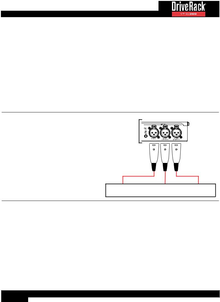
All Analog Connections
When using all analog connections, select either the “Internal 48 kHz” or “Internal 96 kHz” clock source setting. In this configuration, XLR 1 and 2 must be configured for analog operation (these are the default settings from the factory).
VENU360 Utility Settings:
Clock Source: |
Internal 48 kHz or 96 kHz |
XLR 1 Input Format: |
Analog 1 |
SRC: |
N/A |
XLR 2 Input Format: |
Analog 2 |
SRC: |
N/A |
VENU360 Inputs
Analog Device
20

AES Connections From Single Device (48 or 96 kHz)
When both AES connections are made from the same digital device running at a 48 or 96 kHz sample rate, such as a digital mixer, you can clock from either AES input and turn SRC off for both inputs. In this configuration, XLR 1 and 2 must be configured for AES operation. Note that this configuration will also work when using two different digital devices which are clocked to the same clock (for example, using word clock).
VENU360 Utility Settings:
Clock Source: |
AES 1&2 or AES 3&4 |
XLR 1 Input Format: |
AES 1&2 |
SRC: |
OFF |
XLR 2 Input Format: |
AES 3&4 |
SRC: |
OFF |
VENU360 Inputs
|
|
|
|
|
|
|
|
|
|
|
|
Analog Device |
|
|
|
Digital Device |
|
|
(AES 1&2 / AES 3&4 From Same Clock) |
||||
|
|
|
|||
|
|
|
|
|
|
(Optional) |
|
|
|
|
|
AES Connections Using Sample Rate Other Than 48 or 96 kHz
When connecting digital AES sources operating at sample rates other than 48 or 96 kHz, SRC can be used to allow such devices to be used with the VENU360. In this type of application, you must set the VENU360’s clock source to one of the “Internal” options. SRC will automatically
be enabled, allowing the digital signal to be sample rate converted to the internal clock frequency.
VENU360 Utility Settings:
Clock Source: |
Internal 48 kHz or 96 kHz |
XLR 1 Input Format: |
AES 1&2 |
SRC: |
ON |
XLR 2 Input Format: |
AES 3&4 |
SRC: |
ON |
VENU360 Inputs
|
|
|
|
|
|
|
|
|
|
|
|
Analog Device |
|
|
|
Digital Device |
|
|
(Sample Rate Not 48 or 96 kHz) |
||||
|
|
|
|||
|
|
|
|
|
|
(Optional) |
|
|
|
|
|
NOTE: The VENU360 supports sample rates of 48 or 96 kHz. The AES inputs cannot sync to a clock at any sample rate other than 48 or 96 kHz and sample rate conversion must be used with devices operating at other sample rates. When SRC is enabled, the VENU360 supports AES sample rates from 32-192 kHz.
NOTE: SRC is automatically enabled and the parameters become locked whenever one of the “Internal”, “BLU link”, or “Dante” clock options are selected. Therefore, SRC can only be disabled when one of the AES inputs is configured for clock master. This is a safety feature that prevents improper clock source settings when using the AES inputs.
21
AES Connections From Two Different Devices With
Independent Clocks
When two different digital devices are connected to the AES input jacks, you will need to select one to clock to and enable SRC for the other. In this configuration, XLR 1 and 2 must be configured for AES operation.
VENU360 Utility Settings:
Clock Source: |
AES 1&2 |
XLR 1 Input Format: |
AES 1&2 |
SRC: |
OFF |
XLR 2 Input Format: |
AES 3&4 |
SRC: |
ON |
VENU360 Inputs
|
|
|
|
|
|
|
|
|
|
|
|
|
|
|
|
|
|
|
|
|
|
Analog Device |
|
Digital Device 2 |
|
Digital Device 1 |
||||||
|
AES 3&4 (Clock 2) |
|
AES 1&2 (Clock 1) |
|||||||
|
|
|
|
|||||||
|
|
|
|
|
|
|
|
|
|
|
(Optional) |
|
|
|
|
|
|
|
|
|
|
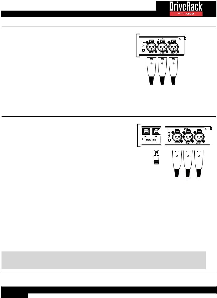
BLU Link Connections (VENU360-B)
When connecting a VENU360-B to other BLU link devices, one of the devices on the ring must provide master clock for all other connected devices. This is accomplished using priorities. Each connected BLU link device is given a “priority”. The BLU link protocol auto-negotiates with all connected devices to determine
which device has the highest priority and the device that wins becomes the master clock for the BLU link ring. In the VENU360-B, the BLU link Priority setting can be set in Utility > BLU link > BLU link Setup. By default, the VENU360-B’s Priority setting is set low to allow another device, such as a mixer, to be the BLU link clock master.
VENU360-B Utility Settings:
Clock Source: |
BLU link |
BLU link Sample Rate: |
Set to match the sample rate |
|
of all other connected BLU link |
|
devices. |
BLU link Priority: |
Set higher than other BLU |
|
link devices to make the |
|
VENU360-B master. Set lower |
|
than another BLU link device |
|
to allow the other device to be |
|
clock master. |
VENU360 Inputs
|
|
|
|
|
|
|
|
|
|
|
|
|
|
|
|
|
|
|
|
|
|
|
|
|
|
|
|
|
|
|
|
|
|
|
|
|
|
|
|
|
|
|
|
|
|
|
|
|
|
|
|
|
|
|
|
|
|
|
|
|
|
|
|
|
BLU link |
|
Analog Device |
|
Digital Device |
||||||||
Device |
|
|
w/ AES Outputs |
|||||||||
|
|
|
|
|
|
|
|
|||||
|
|
|
|
|
|
|
|
|
|
|
|
|
|
|
|
|
|
|
(Optional) |
|
|
(Optional) |
|||
NOTE: In order for BLU link audio to pass through the VENU360-B, the VENU360-B’s Clock Source setting must be set to “BLU link”. When this setting is selected, SRC will automatically be enabled on the AES inputs, allowing the AES and analog inputs to be used alongside BLU link inputs if required for the application.
22
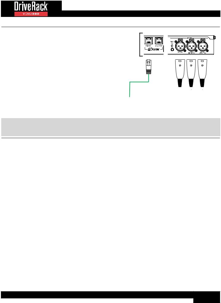
Dante Connections (VENU360-D)
When connecting a VENU360-D to other Dante devices, one of the devices on the network must provide master clock for all other connected devices. All configuration settings for the Dante network, including master clock device designation, must be configured using Audinate’s Dante Controller sotware, available for free on Audinate’s website. The only exception is the Clock Source setting, which must be configured in the VENU360-D as shown below.
VENU360-D Utility Settings:
Clock Source: Dante
VENU360 Inputs
|
|
|
|
|
|
|
|
|
|
|
|
|
|
|
|
|
|
|
|
|
|
|
|
|
|
|
|
|
|
|
|
|
|
|
|
|
|
|
|
|
|
|
|
Dante |
|
|
|
Analog Device |
|
Digital Device |
||||
Device |
|
|
|
|
w/ AES Outputs |
|||||
|
|
|
|
|
|
|
||||
|
|
|
|
|
|
|
|
|
|
|
|
|
|
|
(Optional) |
|
|
(Optional) |
|||
NOTE: In order for Dante audio to pass through the VENU360-D, the VENU360-D’s Clock Source setting must be set to “Dante”. When this setting is selected, SRC will automatically be enabled on the AES inputs, allowing the AES and analog inputs to be used alongside Dante inputs if required for the application.
23

Using Configuration Mode
This section describes how to make manual configuration changes to modify a preset for your application. The easiest way to configure the VENU360 is to use the built-in Wizards. This works well for configuring most systems utilizing full range up to mono 4-way crossover configurations (3-way main speakers with subs), as well as for configuring stage monitors. It also works well for initially configuring the VENU360 for delay fill and zone applications. However, some applications will require further “tweaking” of the configuration in Configuration mode, where you can:
•Edit input channel assignments (VENU360-B and VENU360-D models only)
•Configure signal routing and mixing for input and output processing chains
•Edit processing module insert types
•Link/unlink processing modules
•Configure crossover types
•Edit output names
It is also possible to create an entire configuration from scratch in Configuration mode. For example, you can load any existing or empty preset then edit the configuration from there.
To use Configuration mode:
1. Press the CONFIG button.
2. Select a module using the SELECT wheel and UP/DOWN buttons.
3. Press the SELECT wheel to change the configuration of the selected module. Repeat to make configuration changes to any other modules.
4. When done, press the CONFIG button. A confirmation prompt will appear. See TIP following this table.
24

5. Press the CONFIG button again or the SELECT wheel to apply the changes.
TIP: When done making configuration changes, pressing the CONFIG button twice will perform the “Quick Apply” function, for slightly faster operation.
NOTE: The VENU360 will load the new configuration and automatically mute all outputs – this is a safety feature. When ready to audition the system, unmute the outputs.
NOTE: The VENU360 can intelligently determine which modules have been modified in the configuration and make the necessary changes without losing the settings in all other “untouched” modules in the configuration.
25
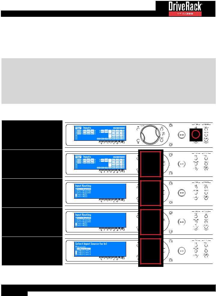
Configuring BLU Link / Dante Inputs
When using the standard VENU360 model, input configuration is fixed with the following assignments: IN1: Analog1, IN2: Analog2, IN3: Analog3, IN4: AES1, IN5: AES2, IN6: AES3, and IN7: AES4. In the VENU360-B and VENU360-D models, inputs are configuable, allowing for the selection of the additional BLU link or Dante input channels. A combination of the analog, AES, and BLU link/Dante channels can be selected. The selected 7 inputs can then be mixed or routed to any available Router or Mixer module in the preset’s signal chain.
IMPORTANT NOTE: When using the VENU360-B model, BLU link channel assignments must be made in the Utility > BLU link submenu or by running the BLU link Setup Wizard. These are the actual BLU link channels assigned to the VENU360-B and are configured separate of presets. This allows VENU360-B BLU link channel assignements to be edited at any time without breaking BLU link routing in all the presets. See ‘BLU LINK’ on page 92 for information on manually editing BLU link channel assignment settings. See ‘Using The Wizards (Wizard Mode)’ on page 17 for information on the BLU link Setup Wizard.
When using the VENU360-D model, Dante input channel assignments to the VENU360-D are made using Audinate’s Dante Controller software.
To configure BLU link or Dante input channels:
1. Press the CONFIG button.
2. If it’s not already selected, select the INPUTS module by turning the SELECT wheel.
3. Press the SELECT wheel to enter the Input Configuration menu.
4. Select the input you wish to edit by turning then pressing the SELECT wheel.
5. Select the desired option by turning then pressing the SELECT wheel.
26

6.Repeat steps 4-5 to edit any additional input channel assignments.
7.When done, press the CONFIG button 3 times to apply the changes.
27

Configuring Mixers/Routers
Input signals in the VENU360 can be mixed or routed to the input processing chains or directly to the output processing chains. On the input processing chains, signals can be mixed or routed from any of the 7 direct inputs (e.g., Analog1, Analog2, AES1, BLU link channel 1, Dante channel 1, etc.). On the output processing chains, signals can also be mixed or routed from any of the 7 direct inputs, as well as the 1/2/3 bus points or A/B/C bus points – including summable variations of the 1/2/3 and A/B/C bus points. The 1/2/3 bus points allow signals to be routed to outputs pre any input processing. The A/B/C bus points allow routing to any outputs post input processing. The below diagrams show all the aforementioned routing/mixing options available to the input and mid (output) processing chains.
Input Mixer/Router Chain Options
Description |
Routing Diagram |
Route IN1 (*Analog 1)
Route IN2 (*Analog 2)
Route IN3 (*Analog 3)
Route IN4
(*AES 1)
Route IN5
(*AES 2)
Route IN6
(*AES 3)
Route IN7
(*AES 4)
Mix Inputs
Mid (Output) Mixer/Router Chain Options
Description |
Routing Diagram |
Route IN1 (*Analog 1)
Route IN2 (*Analog 2)
Route IN3 (*Analog 3)
Route IN4
(*AES 1)
Route IN5
(*AES 2)
Route IN6
(*AES 3)
Route IN7
(*AES 4)
Mix Inputs
Route 1
Route 2
Route 3
Mid (Output) Mixer/Router Chain Options
Description |
Routing Diagram |
Route 1+2
Route 2+3
Route 1+2+3
Mix 1, 2, 3
Route A
Route B
Route C
Route A+B
Route B+C
Route A+B+C
Mix A, B, C
*Fixed input channel configuration in standard VENU360 model. When using a VENU360-D (Dante) or VENU360-B (BLU link) model, input channel configuration can be modified to include Dante or BLU link channels depending on model. See ‘Configuring BLU Link / Dante Inputs’ on page 26 for information on configuring input channels.
28
 Loading...