


Digital Dynamics Processor DDP
Operator Manual
®

C A U T I O N |
RIS K O F ELECTRI C SHOCK |
D O NO T OPEN |
ATTENTION: RISQU E D E CHO C ELECTRIQU E - N E PA S OUVRIR |
WARNING: T O REDUC E TH E RIS K O F FIR E O R ELECTRIC SHOC K D O NO T EXPOS E THI S EQUIPMEN T T O RAI N O R MOISTURE
The symbols shown above are internationally accepted symbols that warn of potential hazards with electrical products. The lightning flash with arrowpoint in an equilateral triangle means that there are dangerous voltages present within the unit. The exclamation point in an equilateral triangle indicates that it is necessary for the user to refer to the owner’s manual.
These symbols warn that there are no user serviceable parts inside the unit. Do not open the unit. Do not attempt to service the unit yourself. Refer all servicing to qualified personnel. Opening the chassis for any reason will void the manufacturer’s warranty. Do not get the unit wet. If liquid is spilled on the unit, shut it off immediately and take it to a dealer for service. Disconnect the unit during storms to prevent damage.
WARNING
FOR YOUR PROTECTION, PLEASE READ THE FOLLOWING:
WATER AND MOISTURE: Appliance should not be used near water (e.g. near a bathtub, washbowl, kitchen sink, laundry tub, in a wet basement, or near a swimming pool, etc). Care should be taken so that objects do not fall and liquids are not spilled into the enclosure through openings.
POWER SOURCES: The appliance should be connected to a power supply only of the type described in the operating instructions or as marked on the appliance.
GROUNDING OR POLARIZATION: Precautions should be taken so that the grounding or polarization means of an appliance is not defeated.
POWER CORD PROTECTION: Power supply cords should be routed so that they are not likely to be walked on or pinched by items placed upon or against them, paying particular attention to cords at plugs, convenience receptacles, and the point where they exit from the appliance.
SERVICING: To reduce the risk of fire or electric shock, the user should not attempt to service the appliance beyond that described in the operating instructions. All other servicing should be referred to qualified service personnel.
FOR UNITS EQUIPPED WITH EXTERNALLY ACCESSIBLE FUSE RECEPTACLE: Replace fuse with same type and rating only.
MULTIPLE-INPUT VOLTAGE: This equipment may require the use of a different line cord, attachment plug, or both, depending on the available power source at installation. Connect this equipment only to the power source indicated on the equipment rear panel. To reduce the risk of fire or electric shock, refer servicing to qualified service personnel or equivalent.
U.K. MAINS PLUG WARNING
A moulded mains plug that has been cut off from the cord is unsafe. Discard the mains plug at a suitable disposal facility. NEVER UNDER ANY CIRCUM-
STANCES SHOULD YOU INSERT A DAMAGED OR CUT MAINS PLUG INTO A 13 AMP POWER SOCKET. Do not use the mains plug without the fuse cover in place. Replacement fuse covers can be obtained from your local retailer. Replacement fuses are 13 amps and MUST be ASTA approved to BS1362.
ELECTROMAGNETIC COMPATIBILITY
This unit conforms to the Product Specifications noted on the Declaration of Conformity. Operation is subject to the following two conditions:
•this device may not cause harmful interference, and
•this device must accept any interference received, including interference that may cause undesired operation.
Operation of this unit within significant electromagnetic fields should be avoided.
• use only shielded interconnecting cables.
SAFETY INSTRUCTIONS
NOTICE FOR CUSTOMERS IF YOUR UNIT IS EQUIPPED WITH A POWER CORD.
WARNING: THIS APPLIANCE MUST BE EARTHED.
The cores in the mains lead are coloured in accordance with the following code:
GREEN and YELLOW - Earth |
BLUE - Neutral |
BROWN - Live |
As colours of the cores in the mains lead of this appliance may not correspond with the coloured markings identifying the terminals in your plug, proceed as follows:
•The core which is coloured green and yellow must be connected to the terminal in the plug marked with the letter E, or with the earth symbol, or coloured green, or green and yellow.
•The core which is coloured blue must be connected to the terminal marked N or coloured black.
•The core which is coloured brown must be connected to the terminal marked L or coloured red.
This equipment may require the use of a different line cord, attachment plug, or both, depending on the available power source at installation. If the attachment plug needs to be changed, refer servicing to qualified service personnel who should refer to the table below. The green/yellow wire shall be connected directly to the unit's chassis.
CONDUCTOR |
WIRE COLOR |
|||
Normal |
Alt |
|||
|
|
|||
|
|
|
|
|
L |
LIVE |
BROWN |
BLACK |
|
|
|
|
|
|
N |
NEUTRAL |
BLUE |
WHITE |
|
|
|
|
|
|
E |
EARTH GND |
GREEN/YEL |
GREEN |
|
WARNING: If the ground is defeated, certain fault conditions in the unit or in the system to which it is connected can result in full line voltage between chassis and earth ground. Severe injury or death can then result if the chassis and earth ground are touched simultaneously.
DECLARATION OF CONFORMITY
Manufacturer’s Name: |
dbx Professional Products |
Manufacturer’s Address: |
8760 S. Sandy Parkway |
|
Sandy, Utah 84070, USA |
declares that the product: |
|
dbx DDP |
|
conforms to the following Product Specifications:
Safety: EN 60065 (1993)
IEC65 (1985) with Amendments 1, 2, 3
EMC: EN 55013 (1990)
EN 55020 (1991)
Supplementary Information:
The product herewith complies with the requirements of the Low Voltage Directive 73/23/EEC and the EMC
Directive 89/336/EEC as amended by Directive 93/68/EEC.
dbx Professional Products
Vice-President of Engineering
8760 S. Sandy Parkway Sandy, Utah 84070, USA March 31,1998
European Contact: Your Local dbx Sales and Service Office or
International Sales Office
68 Sheila Lane
Valparaiso, Indiana
46383, USA
Tel: (219) 462-0938
Fax: (219) 462-4596

Digital Dynamics Processor DDP
Manual Contents
Section 1: Introduction . . . . . . . . . . .2
Unpack . . . . . . . . . . . . . . . . . . . . . . . .2
Quickstart . . . . . . . . . . . . . . . . . . . . . . .2
Section 2: The DDP Tour . . . . . . . . .3
Hardware . . . . . . . . . . . . . . . . . . . . . . .3
Front Panel / Display . . . . . . . . . . . . .3
Rear Panel . . . . . . . . . . . . . . . . . . . .3
Signal Flow . . . . . . . . . . . . . . . . . . . .4
Software . . . . . . . . . . . . . . . . . . . . . . . .5
Setups and Programs . . . . . . . . . . . .5
Gate Section . . . . . . . . . . . . . . . . . . .5
Compressor Section . . . . . . . . . . . . . .5
De-essing Section . . . . . . . . . . . . . . .5
Limiting Section . . . . . . . . . . . . . . . . .5
Sidechain EQ Section . . . . . . . . . . . . .5
Section 3: Setup / Basic Operation . .6
Analog Connections . . . . . . . . . . . . . . . .6
Digital Connections . . . . . . . . . . . . . . . . .6
Midi Connections . . . . . . . . . . . . . . . . . .7
The Curve Window . . . . . . . . . . . . . . . . .7
Software Navigation . . . . . . . . . . . . . . . .8
Threshold Metering . . . . . . . . . . . . . .8
Operating Modes . . . . . . . . . . . . . . . .9
Program Mode . . . . . . . . . . . . . .9
The Bypass Button . . . . . . . . . . .10
Setup Mode . . . . . . . . . . . . . . . .10
Ext. S-chain and the Digital Meters .11
Viewing Elements of a Chain . . . . .13
Linked Programs . . . . . . . . . . . .13
Dual-mono Programs . . . . . . . . .13
Section 4: Editing/Recalling/Saving
Presets . . . . . . . . . . . . . . . . . . . 14
The Store Button . . . . . . . . . . . . . . . . . .14
Moving Around . . . . . . . . . . . . . . . . . . .14
Editing Gates . . . . . . . . . . . . . . . . . . . .14
Editing Compressors . . . . . . . . . . . . . . .15
Editing Limiters . . . . . . . . . . . . . . . . . . .17
Editing De-Essers . . . . . . . . . . . . . . . . . .18
Editing the Sidechain EQ . . . . . . . . . . . . .18
More About Sidechain EQ . . . . . . . |
. . . . |
.19 |
Changing Chain Types . . . . . . . . . . |
. . . . . |
20 |
Saving Programs and Setups . . . . . |
. . . . . |
20 |
Saving a Program . . . . . . . . . . |
. . . . . |
20 |
Saving a Setup . . . . . . . . . . . . |
. . . . . |
21 |
Replace Old . . . . . . . . . . . |
. . . . . |
21 |
Store New . . . . . . . . . . . . |
. . . . . |
21 |
Section 5: Utility Functions . . . |
. . . . |
23 |
Contrast . . . . . . . . . . . . . . . . . . |
. . . . . |
23 |
Sample Rate . . . . . . . . . . . . . . . . |
. . . . . |
23 |
AutoLoad . . . . . . . . . . . . . . . . . . |
. . . . . |
23 |
Digital Input Mode . . . . . . . . . . . . |
. . . . . |
23 |
Digital Output Mode . . . . . . . . . . . |
. . . . . |
24 |
Digital Input Level Controls . . . . . . |
. . . . . |
24 |
MIDI . . . . . . . . . . . . . . . . . . . |
. . . . . |
24 |
SysEx . . . . . . . . . . . . . . . . . . |
. . . . . |
24 |
A/D Calibration . . . . . . . . . . . . . . |
. . . . . |
24 |
Section 6: Appendices . . . . . . . |
. . . . |
25 |
APPENDIX 1: Misc. Information . . . . |
. . . . . |
25 |
Hard Reset . . . . . . . . . . . . . . . |
. . . . |
25 |
Change Default Startup Program . . . . .25 |
||
Front Panel Lockout . . . . . . . . . |
. . . . |
25 |
TYPE IV™ Conversion System . . . |
. . . . |
25 |
TSE™ Tape Saturation Emulation |
. . . . .25 |
|
TCM™ Transient Capture Mode |
. . . . .26 |
|
APPENDIX 2: Factory Setup Listing . . . |
. . . . |
27 |
APPENDIX 3: Factory Program Listing |
. . . .29 |
|
APPENDIX 4: MIDI/SysEx/CC Guide . . |
. . . . |
30 |
Midi Basics . . . . . . . . . . . . . . . . . |
. . . . |
30 |
MIDI Channels . . . . . . . . . . . . . |
. . . . |
30 |
MIDI Changes . . . . . . . . . . . . . |
. . . . |
30 |
Continuous Controller Listing . . . . . . |
. . . . |
30 |
SYSEX Basics . . . . . . . . . . . . . . . . |
. . . . |
31 |
General Format . . . . . . . . . . . . |
. . . . |
31 |
Hex Value Definitions . . . . . . . . . |
. . . . |
31 |
Procedures . . . . . . . . . . . . . . . |
. . . . |
31 |
SysEx Program Dump Sample . . . |
. . . . |
34 |
APPENDIX 5: Factory Service / Warranty . . . |
35 |
|
APPENDIX 6: Specifications . . . . . . . . |
. . . . |
36 |
1

®
Section 1: Introduction
Congratulations on your purchase of the dbx DDP Digital Dynamics Processor. For over 25 years dbx has been the industry leader in dynamics processing. With the introduction of the DDP, we take that same leadership into the digital domain. We are sure you will find the DDP able to meet all your dynamics control needs.
This manual will be your key to understanding the full functionality of the powerful DDP. Read it carefully. After you have become familiar with the unit, we encourage you to experiment and find creative ways that the DDP can make you a better musician and engineer.
Unpack
Your DDP was carefully manufactured, tested, burned in, and packaged at the dbx factory. Before you proceed further, make sure the following items are included in your packaging:
•dbx DDP Digital Dynamics Processor
•Operator’s manual
•Power cord
•Warranty registration card
You should save all packaging materials if possible. They were designed to protect the unit during shipping, and in the unlikely event that your DDP should require service, use only the factory packaging to return it to the factory.
Quickstart
If you are one who prefers to plug and play and read later, follow these simple instructions for setting up the DDP, and get on your way:
1.Make sure that AC power is not connected to the DDP. Turn off the power to your console, recorder, and other devices in your setup.
2.Make audio connections in one of several ways:
A.Wire the analog inputs and outputs into a patch bay. This method will prove to be the most useful in the long run.
B.Connect the DDP’s inputs and outputs directly to the insert point of a console’s input strip, group output, auxiliary send and return, or main outputs.
C.Connect the DDP’s input to another device’s outputs, and connect the DDP’s outputs to the line inputs of a console.
3.With the power switch in the OFF position, connect the power cable (included) to the DDP.
4.Press the LightPipe METER SELECT switch IN to select the INPUT meters for the analog signal. Turn the analog audio input level pots all the way to the OFF (-∞ ) position (fully counter-clockwise). Apply power to the other devices in the setup first, then the DDP. The DDP “wakes up” in the default program mode. You may use the large wheel to the right of the screen to scroll through the various programs.
5.When you have a program selected that suits your application, you can start making sound: make sure there is signal arriving at the DDP’s input, and begin to turn up the INPUT level pots until the LightPipe input meters are peaking at, but not above “+12”. And away you go!
FOR OPTIMUM PERFORMANCE FROM THE DDP, MAKE SURE TO USE PROPER INPUT LEVELS.
2

Digital Dynamics Processor DDP
Section 2: The DDP Tour
HARDWARE
Front Panel
INPUT / OUTPUT LEVEL dBu |
INPUT / OUTPUT LEVEL dBu |
Digital Compressor / Limiter / De-esser / Expander / Gate / Parametric EQ with dbx Type IV™ Conversion System |
NEXT PAGE |
EXP / GATE |
COMPRESSOR |
LIMITER |
-36 -30 -24 -18 -12 -6 0 +6 |
-24 -18 -12 -6 0 +6 +12 +18 |
|
|
|
|
|
|
CH 1 |
|
|
|
POWER |
|
|
|
|
|
|
|
|
DDP |
|
-10 |
+10 |
-10 |
-10 |
+10 |
LOAD |
|
|
|
|
|
0 |
0 |
|
-10 |
DE-ESSER |
SIDECHAIN / EQ |
UTILITY |
|
|
|
|
|
|
|
SELECT |
|
|||
|
-20 |
|
0 |
-20 |
0 |
|
|
|
Digital Dynamics |
|
I/O Meter |
|
|
I/O Meter |
PREV PAGE |
PROGRAM |
STORE |
BYPASS |
Processor |
|
|
|
|
|
|
|
dB +16 |
dB +4 |
dB +16 |
dB +4 |
CH 2 |
INPUT GAIN |
OUTPUT GAIN |
INPUT GAIN |
OUTPUT GAIN |
|
|
CHANNEL 1 |
|
CHANNEL 2 |
|
Analog Input and Output Level Controls
These controls adjust the analog audio levels of the DDP at the input and output stages. Note that the analog output level controls do not affect any digital processing or digital output levels. However, the analog outputs still function while the digital outputs are engaged.
Meter Select Switches
These lightpipe switches select between analog input and output monitoring for the Level Meters.
Level Meters
These meters monitor either analog input or output, depending on the orientation of the Meter Select Buttons.
LCD Display
The large LCD display shows the program, curve, digital meters, parameters, and modules selected by the
Function Buttons and the Data Wheel.
Data Wheel
The Data Wheel changes selected parameters, programs and modules.
Function Buttons
The Function buttons activate the programs, modules, utilities, and parameters of the DDP.
Power Switch
Turns the DDP on and off.
Rear Panel
18 WATTS |
|
|
|
|
MIDI |
CHANNEL TWO |
CHANNEL ONE |
|||
|
|
|
AES/EBU |
|
|
|||||
|
|
® |
|
|
|
|
|
|
|
|
|
|
|
|
|
|
IN |
|
|
|
|
|
|
|
|
|
|
|
OUTPUTS |
INPUTS |
OUTPUTS |
INPUTS |
|
|
PROFESSIONAL PRODUCTS |
|
|
|
|
|
|
|
|
|
|
A HARMAN INTERNATIONAL |
|
|
|
OUT |
|
|
|
|
|
|
COMPANY |
|
|
|
|
|
|
|
|
|
|
SALT LAKE CITY, UTAH |
|
|
|
|
|
|
|
|
100V |
50/60Hz |
MADE IN USA |
INPUT |
OUTPUT |
S/PDIF |
OUT/THRU |
IN |
|
|
|
120V |
60Hz |
MODEL DDP |
|
|
|
|||||
|
|
DIGITAL DYNAMICS PROCESSOR |
|
|
|
|
|
|
|
|
IEC Power Cord Receptacle
IEC Power Cord Receptacle.
Digital I/O (Optional)
The optional Digital I/O card provides digital input and output capabilities in either AES/EBU or S/PDIF formats at 24bit word lengths.
MIDI In and Out/Thru Connectors
These connectors provide full MIDI functionality to the DDP. The Out/Thru jack allows you to use the DDP at any point in the MIDI chain. All automation functions are accessed through the MIDI connectors.
Analog Inputs and Outputs
Each analog channel features both XLR and 1/4” TRS electronically balanced inputs and outputs. They may be used in a balanced or unbalanced configuration. To use unbalanced signal, use a 1/4” TS jack, or ground pin 3 of the XLR cable.
3
®
Section 2: The DDP Tour
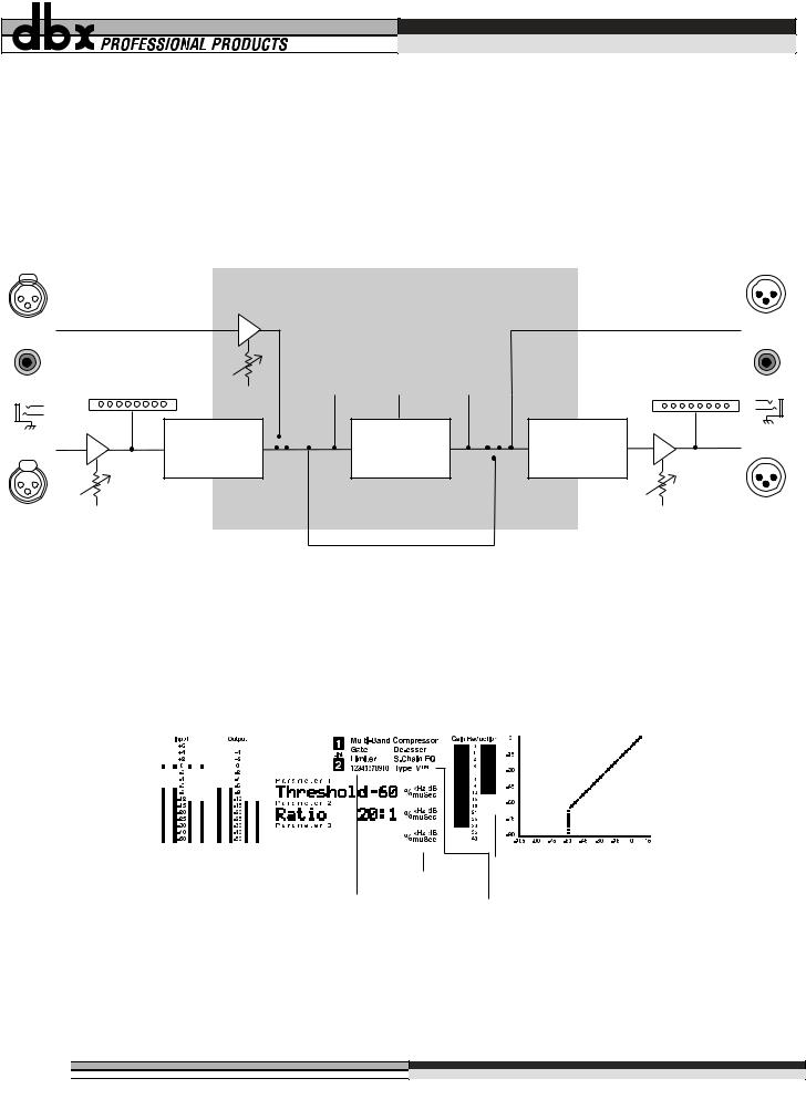
Signal Flow
The following simple illustrations show how audio signal flows through the DDP, and how the LCD display works. They will help you to understand where the DDP’s metering points are located, as well as identify the various elements of the LCD display.
|
digital |
|
input |
|
control |
digital |
|
input |
|
|
analog |
|
input |
|
meter |
analog |
A /D |
input |
Convertor |
digital output
digital |
gain |
digital |
|
analog |
input |
reduction |
output |
|
|
meter |
meter |
meter |
|
output |
|
|
|
|
meter |
|
Dynamics |
|
D / A |
analog |
|
|
output |
||
|
Processor |
|
Convertor |
|
|
|
|
analog |
DSP (Software - based) |
analog |
Operations |
||
input |
|
output |
|
control |
|
control |
|
|
Bypass |
|
|
|
|
|
Figure 1: DDP Signal Flow |
|
|
|
Digital input / |
Program |
|
Chain number |
|
|
|
|
|||||||||||||||||||
|
|
within program |
Chain element |
||||||||||||||||||||||||
|
output meters |
|
|||||||||||||||||||||||||
|
number |
stereo link indicator |
identifier |
||||||||||||||||||||||||
(peak and average) |
|||||||||||||||||||||||||||
|
|
|
|
|
|
|
|
|
|
|
|
|
|
Compression curve graph |
|||||||||||||
|
|
|
|
|
|
|
|
|
|
|
|
|
|
|
|
|
|
|
|
|
|
|
|
|
|
|
|
|
|
|
|
|
|
|
|
|
|
|
|
|
|
|
|
|
|
|
|
|
|
|
|
|
|
|
|
|
|
|
|
|
|
|
|
|
|
|
|
|
|
|
|
|
|
|
|
|
|
|
|
|
|
|
|
|
|
|
|
|
|
|
|
|
|
|
|
|
|
|
|
|
|
|
|
|
|
|
|
|
|
|
|
|
|
|
|
|
|
|
|
|
|
|
|
|
|
|
|
|
|
|
|
|
|
|
|
|
|
|
|
|
|
|
|
|
|
|
|
|
|
|
|
|
|
|
|
|
|
|
|
|
|
|
|
|
|
|
|
|
|
|
|
|
|
|
|
|
|
|
|
|
|
|
|
|
|
|
|
|
|
|
|
|
|
|
|
|
|
|
|
|
|
|
|
|
|
|
|
|
|
|
|
|
|
|
|
|
|
|
|
|
|
|
|
3 parameters |
|
|
|
|
|
per "page" |
Parameter |
|
|
|
|
|
Gain Reduction meter |
||||
measurement |
|||||
Parameter |
units |
Digital |
|||
page number |
|||||
conversion |
|||||
indicator
Figure 2: DDP LCD display
4

Digital Dynamics Processor DDP
Section 2: The DDP Tour
SOFTWARE
The DDP software works on a “building-block” philosophy. Every program number consists of a processing “setup” which is built from processing elements that make up a “chain”. The chain elements may be used in different combinations to produce a desired effect. Once the desired effect is reached, you may rename and save the setup to a user library area. The setup’s chain may consist of any or all of the following: gating effects, compression effects, limiting effects, parametric EQ, sidechain parametric EQ effects, and/or de-essing effects. There are several preset mono and linked setups. For a complete listing of the setups in the DDP, see section 6. Processing setups are linked together using True RMS Power Summing™ (see section 8) for superior stereo operation, or two separate setups may be used in dual mono mode. Each element of the chain has a full complement of parameters that can be manipulated very precisely via the Function buttons and the Data Wheel. The following figure shows the hierarchal building block system used in the DDP.
All Linked Programs |
|
a Linked |
|
a Linked |
||||
are |
|
setup |
which |
|||||
|
|
made |
|
|
|
consists |
chain |
|
|
|
from.. |
|
|
|
of... |
|
|
|
|
|
|
|
|
|
||
|
|
|
|
|
|
|
|
|
|
|
|
|
|
|
|
|
|
|
|
|
|
|
|
|
|
|
|
|
|
|
|
|
|
|
|
|
|
|
|
two |
which each |
a Mono |
||
All Mono Programs |
are |
|
Mono |
consist |
||||
|
setups |
of... |
chain |
|||||
|
|
made |
|
|||||
|
|
from.. |
|
|
|
|
|
|
|
|
|
|
|
|
|
|
|
|
|
|
|
|
|
|
|
|
|
|
|
|
|
|
|
|
|
|
|
|
|
|
|
|
|
|
|
|
|
|
|
|
|
|
|
Figure 3: Program Components
Setups and Programs
Setups are recalled, manipulated and stored individually. Setups must be recalled into programs before they can be accessed for use. Each program has a number assigned to it, and can consist of one or two setups: channel 1 and/or channel 2. Following is a brief description of the various processor elements that make up the DDP processing software.
Gate:
The gate is a dbx expander/gate which gives control over the “ramp” or ratio of the opening, There are also Attack, Hold, and Release times available. Transient Capture Mode™ is also found in the Gate section, with variable delay times available.
For a complete list of the parameters available in the gate, see section 4. For an explanation of Transient Capture Mode, and its implementation in the DDP, see Section 6.
Compressor:
The compressor offers comprehensive control over all parameters. OverEasy® is present, with a variable knee feature (VariKnee™) found only on the DDP. Auto attack and release, and a hold feature make the compressor more unique than other compressors.
For a complete list of the parameters available in the compressor, see section 4.
Limiter:
The limiter offers precise control over Threshold, Attack, and Release. Release times are set in the measurement standard dB/ms.
For a complete description of the limiter, see section 4.
De-Esser:
The DDP’s de-esser allows a wide frequency control range between 800Hz and 8kHz. The range is wide enough to accomplish the most demanding of de-essing needs.
For a complete list of the parameters available in the de-esser, see section 4.
Sidechain EQ / In-Line EQ:
The DDP offers you the ability to do EQ processing in the sidechain circuit without having to hook up an extra unit. It’s easy to perform frequency-specific contouring functions all within the DDP’s software. Also in the EQ section is the new TSE™ Tape Saturation Emulation algorithm, which works in tandem with the TYPE IV™ Conversion System to capture the essence of any analog signal in a pleasing way never accomplished before.
For an explanation of the EQ functions of the DDP, see section 4. For information on the TYPE IV™ Conversion System and its implementation in the DDP see Section 6.
5

®
Section 3: Setup / Basic Operation
ANALOG CONNECTIONS
The DDP is designed to interface as easily as possible to your system. To that end, it may be used in the insert path of a console, in a patch bay, or as a group output processor. Figure 4 shows the DDP used in an insert point of a console. Analog audio connections are made using standard XLR or 1/4” TRS cables. The rear panel is marked as “Channel One” and “Channel Two” to correspond to the way the DDP’s software identifies the two channels of audio. If you are used to using the “left/right” identifiers and plan to use the DDP in such a system, just ensure that each channel of the DDP is consistent in its hookups between the inputs and the outputs (ie: if you use the DDP’s Channel One input in the “left” side of your system, make sure that Channel One’s output also goes to the “left” side of your system). Refer to the illustration of the DDP rear panel on the previous page.
The DDP uses wide ranging analog input and output gain pots that allow the use of either -10dBV or +4dBu connections without the use of a sensitivity selection switch.
18 WATTS |
|
|
|
|
MIDI |
CHANNEL TWO |
CHANNEL ONE |
|
|
|
|
AES/EBU |
AES/EBU |
|
|||
|
|
® |
|
|
|
|
||
|
|
|
|
|
|
IN |
|
|
|
|
PROFESSIONAL PRODUCTS |
|
|
|
|
|
|
|
|
A HARMAN INTERNATIONAL |
|
|
|
OUT |
|
|
|
|
COMPANY |
|
|
|
|
|
|
|
|
SALT LAKE CITY, UTAH |
|
|
|
|
|
|
100V |
50/60Hz |
MADE IN USA |
INPUT |
OUTPUT |
S/PDIF |
OUT/THRU |
IN |
|
120V |
60Hz |
MODEL DDP |
|
|||||
|
|
DIGITAL DYNAMICS PROCESSOR |
|
|
|
|
|
|
Channel 1
OUT |
IN |
INSERT |
INSERT |
IN |
OUT |
Figure 4: DDP Insert Path Connections
DIGITAL CONNECTIONS
If you have purchased the optional digital input / output module for your DDP, you have the ability to perform complex dynamics processing tasks on digital signals without having to leave the digital domain. The DDP Digital I/O also offers the ability to convert analog to digital signals using the proprietary dbx TYPE IV™ Conversion System. The dbx TYPE IV™ algorithms capture an analog signal into the digital domain while maintaining the best qualities of an analog recording, and minimizing the sometimes harsh qualities of digital recordings.
When the digital card is installed in the DDP, the analog outputs are still operative, giving you simultaneous analog and digital output. When digital input is selected via the Utilities button, the analog inputs are disabled. For a complete description of the Utilities functions see Section 5.
18 WATTS |
|
|
|
|
MIDI |
CHANNEL TWO |
CHANNEL ONE |
|||
|
|
|
AES/EBU |
|
|
|||||
|
|
® |
|
|
|
|
|
|
|
|
|
|
|
|
|
|
IN |
|
|
|
|
|
|
|
|
|
|
|
OUTPUTS |
INPUTS |
OUTPUTS |
INPUTS |
|
|
PROFESSIONAL PRODUCTS |
|
|
|
|
|
|
|
|
|
|
A HARMAN INTERNATIONAL |
|
|
|
OUT |
|
|
|
|
|
|
COMPANY |
|
|
|
|
|
|
|
|
|
|
SALT LAKE CITY, UTAH |
|
|
|
|
|
|
|
|
100V |
50/60Hz |
MADE IN USA |
INPUT |
OUTPUT |
S/PDIF |
OUT/THRU |
IN |
|
|
|
120V |
60Hz |
MODEL DDP |
|
|
|
|||||
|
|
DIGITAL DYNAMICS PROCESSOR |
|
|
|
|
|
|
|
|
Figure 5: The DDP rear panel
6

Digital Dynamics Processor DDP
Section 3: Setup / Basic Operation
MIDI CONNECTIONS
The DDP has a full complement of MIDI functionality. The MIDI connectors on the Rear Panel are configured in the traditional way: with an “In” jack and an “Out/Thru” jack. The DDP can be used in common MIDI systems at any point in the MIDI chain. MIDI setup functions are accessed with the Utilities button and are generally the same as the functionality you are used to with most other MIDI devices. Program numbers and setups may be changed and bypassed via the standard MIDI commands. In addition, presets may be saved off of the DDP and reloaded via the MIDI functions. Full SysEx and Continuous Controller functions are also a part of the DDP’s architecture. A full explanation of the MIDI, SysEx and CC functions are discussed in Section 5.
THE CURVE WINDOW
After you have chosen a program, you will want to change some of the parameters to meet your specific needs. One of the most useful tools available on the DDP for setting up a proper compression curve is the curve window. In the curve window you can see the combined effects of all compression-related parameters expressed in a graphical format. The figure below shows the different parts of the curve window you will see as you edit the gate, compressor, and limiter functions of the DDP.
When working with the sidechain EQ, or the in-line EQ, the curve window changes to show a graphical representation of the 3 parametric bands in a frequency grid. Your adjustments to the three bands are shown in real time.
Additionally, the de-esser has its own graphical way of displaying its parameters, as seen above. The frequency is shown on the bottom, or X axis, and the amount is shown on the side, or Y axis. Again, changes to the parameters are updated in real time.
limiter threshold
compressor |
limiter output |
ratio |
|
compressor threshold
|
|
Boost |
|
Output |
|
or |
Level |
normal or |
Cut |
|
|
|
|
||
gate |
unprocessed signal |
|
|
(1:1 ratio) |
|
|
|
threshold |
|
|
|
|
|
|
|
Input |
|
Frequency |
Frequency |
|
gate ratio |
|
|
Figure 6:The compression curve window, the EQ window, and the De-Esser window
7

®
Section 3: Setup / Basic Operation
SOFTWARE NAVIGATION Threshold Metering
On every program, you will find threshold metering for each element of the processing setup. These take the same form as the now-standard dbx 10 Series processors’ threshold meters: a plus (+) or minus (-) sign in a square box.
Figure 7: The DDP’s threshold meters |
Compressor Threshold Meter
Gate Threshold Meter
Limiter Threshold Meter
De-Esser Threshold Meter
Compressor
For the compressor, the threshold meter has three segments. (See figure 7 above.) The first is the minus (-) sign. It indicates that the threshold that is set in the compressor section is not being exceeded by the program material. There is no processing taking place in the compressor section if the threshold is not being exceeded, no matter what the other compressor settings are. The next part of the threshold meter is the “o”. It represents the OverEasy range of compression. When the signal level is in the OverEasy® range, the “o” part of the meter will be blackened, indicating that the signal is in the soft knee mode of compression. (For a complete explanation of the OverEasy® parameter, see section 4.) The third segment of the compressor meter is the plus (+) sign. It is blackened when the signal is being fully compressed at the ratio set by the Ratio Parameter control.
Limiter
The limiter’s threshold meter works on the same principle: when the signal is under the threshold setting (which is set in the limiter section), the signal is not being processed by the limiter section. If the DDP’s screen shows that you are getting gain reduction, it is through some other chain element. To determine which element is triggering gain reduction, look at the other threshold meters to determine which element’s threshold is being exceeded by the signal. When the signal exceeds the threshold set in the limiter section, the plus (+) sign will darken, and gain reduction will begin to occur as a result of the signal exceeding the limiter’s threshold.
Gate
When the signal is under the threshold set in the gate section, the gate is “closed”, or signal is not being passed through. The gate section is before the compressor and limiter sections in all chain types, and if the signal is not being passed through the gate, the other elements of the chain will not be activated.
When the signal is under the threshold, the minus (-) sign is darkened, and when the signal passes over the threshold, the plus (+) sign is darkened
De-Esser
The De-esser also has a threshold meter. The threshold meter for this element is also displayed in the upper left corner. When the plus sign is reversed - white “+” on black background, the threshold has been exceeded and de-essing is being applied to the signal.
8
Digital Dynamics Processor DDP
Section 3: Setup / Basic Operation
Operating Modes
Program Mode
The DDP comes ready to turn on in “Program Mode”. There are a series of 50 factory programs, as well as enough room to name and store up to 50 of your own programs. The factory designed programs have been given obvious names, according to application and should be a good jumping off point for all of your processing needs. They cannot be erased. Their names and characteristics are listed in section 5. At the factory, the factory-designed programs were also copied into the re-writable user program area. A program can be erased at any time by saving a program in its place.
After you have set up and turned on the DDP, it will be in “program” mode and will show something like the following in the middle section of the LCD display screen:
Figure 8: Sample display showing Program #28, Setup 1 is “small Voc” and Setup 2 is “De-Ess Voc”.
The large number on the display indicates the program number. It is the method used to bookmark programs, and all programs have a program number. Each program can store either a linked setup, or two dual mono setups.
There are two ways to take a look at the setup for any program:
1.While in “program” mode, the display will show the chain for each setup in the curve window, located on the far right side of the display. The abbreviation for each chain element is as follows:
Equalizer: EQ |
|
Gate: G |
Compressor: C or Cmp |
|||||||
Limiter: L |
|
De-Esser: DS |
Sidechain EQ: SEQ |
|||||||
|
|
Gain |
|
|
|
|
|
|
|
|
|
|
Reduction |
|
|
|
|
|
|
|
|
Program |
|
Meter |
|
|
|
|
|
|
|
|
|
|
|
|
|
|
|
|
|
|
|
Number |
|
Channel |
|
Channel 1 |
||||||
|
|
Identifier |
|
|||||||
|
|
|
Chain Type |
|||||||
|
|
|
|
|
||||||
|
|
|
|
|
|
|
|
|
|
|
|
|
|
|
|
|
|
|
|
|
|
Program |
|
|
|
|
|
|
|
|
|
Channel 1 |
|
|
|
|
|
|
|
|
|
||
|
|
|
|
|
|
|
|
|||
Name |
|
|
|
|
|
|
|
|
Threshold Meters |
|
|
|
|
|
|
|
|
|
|||
|
|
|
|
|
|
|
|
|
|
|
Channel 2
Channel 1 |
|
|
|
|
|
|
Chain Type |
Setup Name |
|
|
|
|
|
|
|
|
|
|
|
|
|
|
|
|
|
|
|
|
|
Channel 1 |
|
|
Channel 2 |
|
|
||||
|
|
Threshold Meters |
|||||
|
Setup Name |
|
|||||
|
|
|
|
|
|||
Figure 9: Display showing elements of each setup in a dual mono program.
9

®
Section 3: Setup / Basic Operation
2.Press the “CH 1” or “CH 2” button, (depending on which setup you want to look at) while the “program” button’s light is on. This method only lets you see the setup for one channel at a time. The contents of the setup, or the setup’s chain, will be displayed in the third line of text. As you do this, the program LED will go off, and the LED on the button you pressed will light, indicating that you are now looking at channel one’s (or two’s) setup. In addition to this telemetry, there will be text which says “USER setup” or “FACTORY Setup” in the curve window on the far right side of the display. By turning the Data Wheel, you can scroll through them. You will notice the various factory setups as well as all your user setups. You can store up to 100 linked setups, and 100 mono setups. As you do more projects with your DDP, you will begin to gather all types of setups that you have designed and saved for yourself. You are now in “setup” mode. Using the Data Wheel, scroll through the available setups for the program you have chosen. You will see the 3 linked chain types if you are in a linked program number, or you will see the 6 chains for mono setups if you are in a dual mono program number.
To get out of setup mode and back to program mode, simply touch the program button. The LED associated with the Channel button will turn off and the Program button LED will turn on.
“CH 1” Button
“CH 2” Button
NEXT PAGE |
EXP / GATE |
COMPRESSOR |
LIMITER |
CH 1 |
|
|
|
SELECT |
DE-ESSER |
SIDECHAIN / EQ |
UTILITY |
LOAD |
|
|
|
PREV PAGE |
PROGRAM |
STORE |
BYPASS |
CH 2 |
|
|
|
“PROGRAM” Button
Figure 10: Function buttons and LCD display in chain mode.
While in program mode, you may scroll through the different factory designed programs by simply turning the Data Wheel. By default, the DDP is shipped with the AutoLoad feature activated. This means that the program number displayed on the screen is the one which is active, scrolling though the programs cancels any changes you made to the program you last edited. (See Section 4 for details on editing and storing programs and chains, and Section 5 for more information on AutoLoad and other utility features) In AutoLoad mode, it’s best to scroll through programs while in “Bypass” mode. Enter Bypass mode by pressing the Bypass button. Its LED will light indicating that the DDP is in Bypass mode.
The Bypass Button
The Bypass button on the DDP works like an analog processor, in order to give you more visual feedback. When you engage the bypass mode, the DDP’s meters continue to operate, giving you the ability to change and adjust parameters while bypassed. Refer to figure 1 for more information on where the DDP’s metering points are located. It may take a little practice to adjust parameters without being able to hear the effects of the adjustments. However, this feature is very useful in that it allows you to change programs, setups or parameters in a live situation without subjecting your audio system or an audience to the sudden change. Simply bypass the DDP, make your changes, make sure the meters are showing the desired effect, then take the DDP out of Bypass mode.
Setup Mode
Setup mode is the method by which you will manipulate parameters to make them fit your application exactly. While every effort was made to produce factory presets that work for most applications, it should be noted that no two systems, situations or applications are exactly alike. Therefore you will have to change and fine tune the parameters in the chains that have been provided for you. As you become familiar with this process, you will become more adventurous and creative in setting up your DDP for various applications. In dual mono mode, each chain is manipulated separately. In linked mode, the stereo pair shows up on the screen as one chain, and therefore only needs to be edited once.
10
 Loading...