


® |
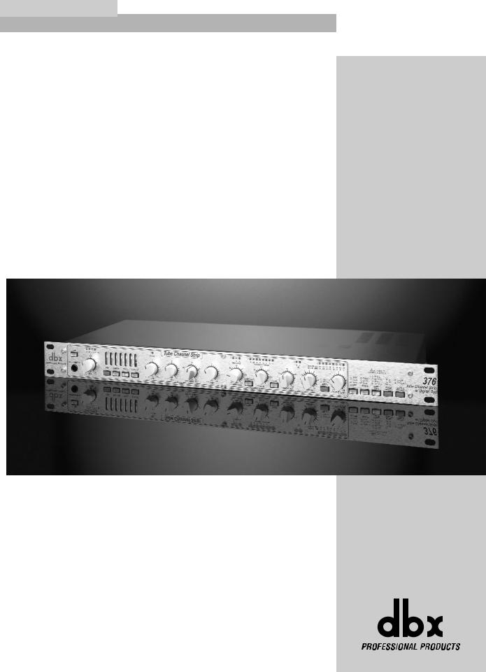
376 |
Vacuum Tube |
Channel Strip |
w/Digital Out |
User Manual |

IMPORTANT SAFETY INSTRUCTIONS
C A U T I O N |
RIS K O F ELECTRI C SHOCK |
D O NO T OPEN |
ATTENTION: RISQU E D E CHO C ELECTRIQU E - N E PA S OUVRIR |
WARNING: T O REDUC E TH E RIS K O F FIR E O R ELECTRIC SHOC K D O NO T EXPOS E THI S EQUIPMEN T T O RAI N O R MOISTURE
The symbols shown above are internationally accepted symbols that warn of potential hazards with electrical products. The lightning flash with arrowpoint in an equilateral triangle means that there are dangerous voltages present within the unit. The exclamation point in an equilateral triangle indicates that it is necessary for the user to refer to the owner’s manual.
These symbols warn that there are no user serviceable parts inside the unit. Do not open the unit. Do not attempt to service the unit yourself. Refer all servicing to qualified personnel. Opening the chassis for any reason will void the manufacturer’s warranty. Do not get the unit wet. If liquid is spilled on the unit, shut it off immediately and take it to a dealer for service. Disconnect the unit during storms to prevent damage.
SAFETY INSTRUCTIONS
NOTICE FOR CUSTOMERS IF YOUR UNIT IS EQUIPPED WITH A POWER CORD.
WARNING: THIS APPLIANCE MUST BE EARTHED.
The cores in the mains lead are coloured in accordance with the following code:
GREEN and YELLOW - Earth |
BLUE - Neutral |
BROWN - Live |
As colours of the cores in the mains lead of this appliance may not correspond with the coloured markings identifying the terminals in your plug, proceed as follows:
•The core which is coloured green and yellow must be connected to the terminal in the plug marked with the letter E, or with the earth symbol, or coloured green, or green and yellow.
•The core which is coloured blue must be connected to the terminal marked N or coloured black.
•The core which is coloured brown must be connected to the terminal marked L or coloured red.
This equipment may require the use of a different line cord, attachment plug, or both, depending on the available power source at installation. If the attachment plug needs to be changed, refer servicing to qualified service personnel who should refer to the table below. The green/yellow wire shall be connected directly to the units chassis.
CONDUCTOR |
WIRE COLOR |
|||
|
|
|||
Normal |
Alt |
|||
|
|
|||
|
|
|
|
|
L |
LIVE |
BROWN |
BLACK |
|
|
|
|
|
|
N |
NEUTRAL |
BLUE |
WHITE |
|
E |
EARTH GND |
GREEN/YEL |
GREEN |
|
WARNING: If the ground is defeated, certain fault conditions in the unit or in the system to which it is connected can result in full line voltage between chassis and earth ground. Severe injury or death can then result if the chassis and earth ground are touched simultaneously.
WARNING FOR YOUR PROTECTION
PLEASE READ THE FOLLOWING:
KEEP THESE INSTRUCTIONS
HEED ALL WARNINGS
FOLLOW ALL INSTRUCTIONS
CLEAN ONLY WITH A DAMP CLOTH.
DO NOT BLOCK ANY OF THE VENTILATION OPENINGS. INSTALL IN ACCORDANCE WITH THE MANUFACTURERS INSTRUCTIONS.
DO NOT INSTALL NEAR ANY HEAT SOURCES SUCH AS RADIATORS, HEAT REGISTERS, STOVES; OR OTHER APPARATUS (INCLUDING AMPLIFIERS) THAT PRODUCE HEAT.
ONLY USE ATTACHMENTS/ACCESSORIES SPECIFIED BY THE MANUFACTURER.
UNPLUG THIS APPARATUS DURING LIGHTNING STORMS OR WHEN UNUSED FOR LONG PERIODS OF TIME.
WATER AND MOISTURE: Appliance should not be used near water (e.g. near a bathtub, washbowl, kitchen sink, laundry tub, in a wet basement, or near a swimming pool, etc). Care should be taken so that objects do not fall and liquids are not spilled into the enclosure through openings.
POWER SOURCES: The appliance should be connected to a power supply only of the type described in the operating instructions or as marked on the appliance.
GROUNDING OR POLARIZATION: Precautions should be taken so that the grounding or polarization means of an appliance is not defeated.
POWER CORD PROTECTION: Power supply cords should be routed so that they are not likely to be walked on or pinched by items placed upon or against them, paying particular attention to cords at plugs, convenience receptacles, and the point where they exit from the appliance.
SERVICING: To reduce the risk of fire or electric shock, the user should not attempt to service the appliance beyond that described in the operating instructions. All other servicing should be referred to qualified service personnel.
FOR UNITS EQUIPPED WITH EXTERNALLY ACCESSIBLE FUSE RECEPTACLE: Replace fuse with same type and rating only.
MULTIPLE-INPUT VOLTAGE: This equipment may require the use of a different line cord, attachment plug, or both, depending on the available power source at installation. Connect this equipment only to the power source indicated on the equipment rear panel. To reduce the risk of fire or electric shock, refer servicing to qualified service personnel or equivalent.

IMPORTANT SAFETY INSTRUCTIONS
LITHIUM BATTERY
WARNING
CAUTION!
This product may contain a lithium battery.There is danger of explosion if the battery is incorrectly replaced. Replace only with an Eveready CR 2032 or equivalent. Make sure the battery is installed with the correct polarity. Discard used batteries according to manufacturer’s instructions.
ADVARSEL!
Lithiumbatteri - Eksplosjonsfare.Ved utskifting benyttes kun batteri som anbefalt av apparatfabrikanten. Brukt batteri returneres apparatleverandøren.
ADVARSEL!
Lithiumbatteri - Eksplosionsfare ved fejlagtig håndtering. Udskiftning må kun ske med batteri av samme fabrikat og type. Levér det brugte batteri tilbage til leverandøren.
VAROITUS!
Paristo voi räjähtää, jos se on virheellisesti asennettu.Vaihda paristo ainoastaan laitevalmistajan suosittelemaan tyyppin. Hävitä käytetty paristo valmistajan ohjeiden mukaisesti.
VARNING!
Explosionsfara vid felaktigt batteribyte. Använd samma batterityp eller en ekvivalent typ som rekommenderas av apparattillverkaren. Kassera använt batteri enligt fabrikantens instruktion.
ELECTROMAGNETIC
COMPATIBILITY
This unit conforms to the Product Specifications noted on the Declaration of Conformity. Operation is subject to the following two conditions:
•this device may not cause harmful interference, and
•this device must accept any interference received, including interference that may cause undesired operation.
Operation of this unit within significant electromagnetic fields should be avoided.
• use only shielded interconnecting cables.
U.K. MAINS PLUG WARNING
A molded mains plug that has been cut off from the cord is unsafe. Discard the mains plug at a suitable disposal facility. NEVER UNDER ANY CIRCUMSTANCES SHOULD YOU INSERT A DAMAGED OR CUT MAINS PLUG INTO A 13 AMP POWER SOCKET. Do not use the mains plug without the fuse cover in place. Replacement fuse covers can be obtained from your local retailer. Replacement fuses are 13 amps and MUST be ASTA approved to BS1362.
DECLARATION OF
CONFORMITY
Manufacturer’s Name: |
dbx Professional Products |
|
Manufacturer’s Address: |
8760 S. Sandy Parkway |
|
|
Sandy, Utah 84070, USA |
|
declares that the product: |
|
|
|
Product name: |
dbx 376 |
|
Note: Product name may be suffixed by the letters - EU. |
|
|
Product option: |
N/A |
conforms to the following Product Specifications: |
|
|
EMC: |
EN 55013 (1990) |
|
EN 55020 (1991) |
|
|
Supplementary Information:
The product herewith complies with the requirements of the Low Voltage Directive 72/23/EEC and the EMC Directive 89/336/EEC as amended by Directive 93/68/EEC.
|
dbx Professional Products |
|
Vice-President of Engineering |
|
8760 S. Sandy Parkway |
|
Sandy, Utah 84070, USA |
|
October 1, 2000 |
European Contact: |
Your local dbx Sales and Service Office |
|
or Harman Music Group |
|
8760 South Sandy Parkway |
|
Sandy, Utah 84070 USA |
|
Tel: (801) 568-7533 |
|
Fax: (801) 568-7583 |

|
|
376 |
|
|
Table of Contents |
|
Introduction |
|
Section 3 - Digital Applications |
|
|||
0.1 |
Defining the 376................................................ |
i |
3.1 |
Digital Output Front Panel Functions........... |
12 |
|
0.2 |
Service Contact Info......................................... |
ii |
3.2 |
Digital Rear Panel Connections..................... |
12 |
|
0.3 |
Warranty............................................................ |
ii |
3.3 |
Sync Input Sample Rate Selection................. |
13 |
|
0.4 |
Installation Recommendations........................ |
iii |
3.4 |
Direct Connection to a DAW (CPU) ............. |
14 |
|
Section 1 - Getting Started |
|
3.5 |
Direct Connection to a Digital Mixer............ |
15 |
||
|
3.6 |
A/D Conversion |
16 |
|||
|
|
|
|
|||
1.1 |
Rear Panel Connections ................................... |
2 |
3.7 |
Multi-Tracking to Digital |
17 |
|
|
|
|
|
|||
1.2 |
Front Panel Connections.................................. |
3 |
|
|
|
|
|
|
|
|
3.8 |
Analog and Digital Output Applications ...... |
18 |
1.3 |
Type IV™ Conversion System Controls.......... |
4 |
|
|
|
|
Section 2 - Analog Applications |
|
Appendix |
|
|||
|
|
|
|
|||
2.1 |
Basic Connection |
8 |
A- Sync Input Info................................................ |
20 |
||
|
|
|
||||
2.2 |
Connection to a Mixing Console |
8 |
B- Block Diagram ................................................. |
21 |
||
|
|
|
||||
2.3 |
Direct Connection to a Recorder |
9 |
C- dbx Type IV™ Conversion System................. |
22 |
||
|
|
|
||||
|
|
|
|
D.1 Noise-Shaping Algorithms............................. |
27 |
|
|
|
|
|
D.2 Truncation ...................................................... |
27 |
|
|
|
|
|
D.3 Specifications ................................................. |
28 |
|
®
Table of Contents 376 User Manual

376
INTRODUCTION
INTRO
CUSTOMER SERVICE INFO
376 DEFINED
WARRANTY INFO
®

|
|
Introduction |
376 |
|
|
|
|
||
|
|
|
||
INTRODUCTION |
Congratulations on your purchase of the dbx 376 Vacuum Tube Channel Strip with digital capa- |
|||
bilities. For over 25 years, dbx has been the industry leader in dynamics processing. With the |
||||
|
||||
|
introduction of the 376, the standard for channel strip processors has now been completely |
|||
|
redefined. Conventional channel strip processors are often limited in their ability to color and |
|||
|
control the tonal characteristics of a vocal or mic’d application. The 376 however, offers, a |
|||
|
Vacuum Tube Preamp section, a 3-Band Parametric EQ section, built-in Compressor and |
|||
|
De-Essing capabilities. In addition to the impressive list of effects available, the 376 also offers |
|||
|
the state-of-the-art proprietary dbx Type IV™ conversion system to offer the best characteristics |
|||
|
of both analog and digital applications all under one roof. |
|
||
|
This manual will be your guide to understanding the full functionality of the powerful 376. After |
|||
|
you have become familiar with the unit, we encourage you to experiment and find creative |
|||
|
ways that the 376 can help you optimize your specific application. |
|
||
|
|
|
|
|
0.1 Defining the 376
The dbx 376 Vacuum Tube Preamp/Channel strip provides the user with Vacuum tube microphone preamp capabilities in the analog domain as well as giving you pristine digital output capabilities. Listed below, are some of features available to you in the 376:
•Tube microphone pre-amp
•200V tube plate voltage
•4-Segment Drive meter LEDs
•Front panel instrument input
•Selectable mic/line switch
•+48 Volt phantom power
•20 dB pad
•3-Band Parametric EQ
•Compressor
•De-Esser
•Compressor Threshold and Gain Reduction meters
•De-Esser Gain Reduction meter
•8 segment output meter
•Type IV™ conversion system
•AES/EBU and S/PDIF digital outputs
•Word clock sync input and output
•Selectable sampling rates (96, 88.2, 48, 44.1kHz)
•24, 20 and 16 bit wordlengths
•Selectable dither and noise-shaping algorithms
With the dbx proprietary patent-pending TSE™ Tape Saturation Emulation and TYPE IV™ Conversion System, your signal retains its analog warmth and character, with the pristine clarity demanded by today’s digital standards. In addition, the 376 offers 96kHz A/D conversion, which results in improved frequency response.
®
i |
376 User Manual |
|
|

376 Introduction
0.2 Service Contact Info
If you require technical support, contact dbx Customer Service. Be prepared to accurately describe the problem. Know the serial number of your unit. This is printed on a sticker attached to the rear panel. If you have not already taken the time to fill out your warranty registration card and send it in, please do so now.
Before you return a product to the factory for service, we recommend you refer to the manual. Make sure you have correctly followed installation steps and operation procedures. If you are still unable to solve a problem, contact our Customer Service Department at (801) 568-7660 for consultation. If you need to return a product to the factory for service, you MUST contact Customer Service to obtain a Return Authorization Number.
No returned products will be accepted at the factory without a Return Authorization Number.
Please refer to the warranty below, which extends to the first end-user. After expiration of the warranty, a reasonable charge will be made for parts, labor, and packing if you choose to use the factory service facility. In all cases, you are responsible for transportation charges to the factory. dbx will pay return shipping if the unit is still under warranty.
Use the original packing material if it is available. Mark the package with the name of the shipper and with these words in red: DELICATE INSTRUMENT, FRAGILE! Insure the package properly. Ship prepaid, not collect. Do not ship parcel post.
0.3 Warranty
This warranty is valid only for the original purchaser and only in the United States.
1). The warranty registration card that accompanies this product must be mailed within 30 days after purchase date to validate this warranty. Proof-of-purchase is considered to be the burden of the consumer.
2). dbx warrants this product, when bought and used solely within the U.S., to be free from defects in materials and workmanship under normal use and service.
3). dbx liability under this warranty is limited to repairing or, at our discretion, replacing defective materials that show evidence of defect, provided the product is returned to dbx WITH RETURN AUTHORIZATION from the factory, where all parts and labor will be covered up to a period of two years. A Return Authorization number must be obtained from dbx by telephone. The company shall not be liable for any consequential damage as a result of the product's use in any circuit or assembly.
4). dbx reserves the right to make changes in design or make additions to or improvements upon this product without incurring any obligation to install the same additions or improvements on products previously manufactured.
5). The foregoing is in lieu of all other warranties, expressed or implied, and dbx neither assumes nor authorizes any person to assume on its behalf any obligation or liability in connection with the sale of this product. In no event shall dbx or its dealers be liable for special or consequential damages or from any delay in the performance of this warranty due to causes beyond their control.
®
376 User Manual |
ii |
|
|

|
Introduction |
376 |
|
|
|
|
|
|
0.4 Installation Recommendations
FOR RACK MOUNT USE ONLY - Install the 376 in your rack with the provided rack screws. When installed in a rack, the unit should be positioned with enough room (at least one 1U above the and 1U below the unit) to allow proper ventilation. The 376 should not be mounted above or below anything that generates excessive heat. Ambient temperatures should not exceed 1130F (450C) when equipment is in use. Although the unit is shielded against radio frequency and electromagnetic interference, extremely high fields of RF and EMI should be avoided where possible.
®
iii |
376 User Manual |
|
|
376 |
Section 1 |
|
Getting Started |
|
|
Getting
Started
®
Section 1 |
376 |
Getting Started
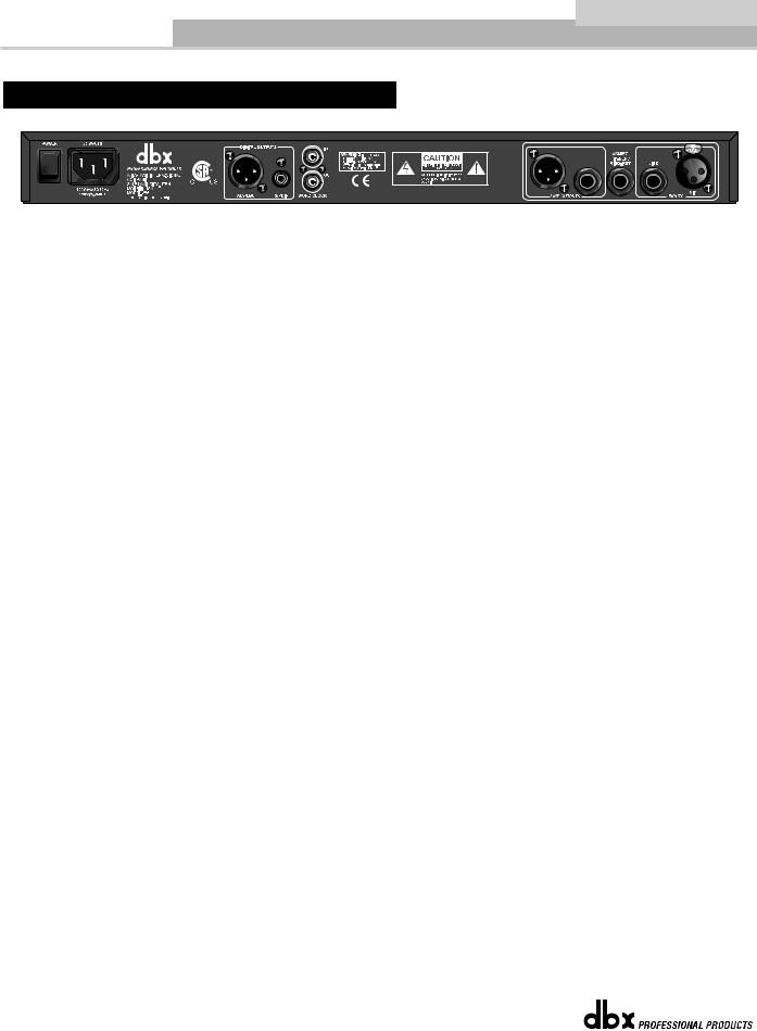
1.1 Rear Panel Connections
Power Switch
Turns the 376 on and off.
IEC Power Cord Receptacle
This is the power cord receptacle of the 376. An IEC cord is included with the shipped product.
AES/EBU Digital Connector
Th e |
3 7 6 p r o v id e s |
A E S/E B U d ig ita l |
o u tp u t |
fo r m a ttin g th r o u g h |
th e X L R |
c o n n e c to r . |
B e s u r e to |
||
u s e |
s h o r t le n g th s |
o f 1 1 0 Ω d ig ita l |
c a b le s |
r a th e r |
th a n |
s ta n d a r d |
X L R to |
X L R c a b le s . |
Us in g th e |
c o r r e c t c a b le s w ill p r e v e n t d ig ita l d r o p o u ts a n d |
o th e r |
in te r c o n n e c tio n |
p r o b le m s . |
|
|||||
S/PDIF Digital Connector
Th e 3 7 6 p r o v id e s S/P D IF d ig ita l o u tp u t fo r m a ttin g th r o u g h th e R C A c o a x ia l c o n n e c to r . B e s u r e
to |
u s e |
s h o r t le n g th s o f 7 5 |
Ω d ig ita l c a b le s o r 7 5 Ω v id e o c a b le s r a th e r th a n |
s ta n d a r d a u d io R C A |
to |
R C A |
c a b le s . Us in g th e |
c o r r e c t c a b le s w ill p r e v e n t d ig ita l d r o p o u ts a n d |
o th e r in te r c o n n e c - |
tio n p r o b le m s . |
|
|
||
NOTE: Although digital information is coming out of both XLR and RCA jacks simultaneously, the correct format will only appear at the output for the format type selected. For example, if you have AES/EBU format selected, an AES/EBU formatted signal will appear at the output of both the XLR and the RCA connector. Or, if you have S/PDIF format selected, an S/PDIF formatted signal will appear at the output of both the RCA and XLR connectors.
Sync In and Out Connectors
BNC connectors are provided for both clock in and out functions. The 376’s clock chips are dbx custom VCXO chips, designed for low-jitter performance. You may use the 376 as a master clock source, having other equipment slave to the 376, or you may slave the 376’s clock to any other wordclock source device.
Line Output Connectors
The analog output section of the 376 offers both XLR and 1/4" TRS electronically balanced connections. The 1/4” connector may be used in a balanced or unbalanced configuration. Using a 1/4” TS connector will unbalance the signal.
Insert Jack
The 1/4” TRS Insert jack (Tip=SEND and Ring=RETURN), will allow you to add an effects loop directly into the signal path of the 376. This insertion point is located after the tube sec-
tion and prior to the signal processing section.
Analog Input Connectors
The analog input section of the 376 offers both XLR (Microphone) and a rear 1/4" TRS (Line) electronically balanced connections. The 1/4” connector may be used in a balanced or unbalanced configuration. Using a 1/4” TS connector will unbalance the signal.
®
2 |
376 User Manual |
|
|
376 |
Getting Started |
Section 1 |
1.2 Front Panel Controls
Instrument Input
This unbalanced high-impedance input connection is used to insert an instrument signal directly into the preamp. Use the LINE switch to make instrument input or the rear panel line input active. Plugging into the instrument jack will override the rear panel 1/4” input jack (line input must be selected).
Line Select Switch
This switch, when lit, selects the rear line input or front panel instrument input (when something is connected) as the source signal of the 376.
Drive Control
This control sets the amount of gain at the input of the vacuum tube stage. The range of gain available is +30 to +60 dB (-15 to +15 dB when LINE INPUT is selected).
Drive meter
This 4-segment LED meter indicates the input drive signal.
+48 Volt Switch
This switch activates phantom power for condenser microphones on pins 2 and 3 of the XLR mic input. You should connect your microphone before turning on the phantom power to prevent damage to your microphone. Be sure to always lower levels prior to using the +48 Volt Switch.
20db Pad Switch
This switch attenuates the microphone input signal by 20dB.
Phase Switch
This switch inverts the phase of the incoming signal at the Mic input by swapping pins 2 and 3 on the XLR connector.
Note- The +48 Vo lt , 20dB Pad and Phase functions are only available when the microphone input is in use.
Low Cut Switch
This switch places a 12 dB per octave shelving high pass filter in the signal path. The knee frequency of the Low Cut filter is 75 Hz. This filter is very useful for removing low frequency rumble or handling noise from a microphone input signal.
®
376 User Manual |
3 |
|
|

Section 1 |
Getting Started |
376 |
|
|
|
|
|
|
Low control
This control varies the gain of the low frequency equalization; the gain range is -15 to +15 dB. This filter is a low shelving filter at 80 Hz.
Mid control
This control varies the gain of the mid frequency equalization; the gain range is -15 to + 15 dB. The mid frequency filter is a bandpass configuration with variable frequency.
Frequency control
This control selects the center frequency for the mid frequency filter. The frequency range is 100 Hz to 8 kHz.
High control
This control varies the gain of the high frequency equalization; the gain range is -15 to +15 dB. This filter is a low shelving filter at 12 kHz.
EQ Clip LED
This LED indicates that the signal is clipping within the EQ section of the 376.
Threshold (Compressor)
This control is used to set the threshold of compression from -40dBu (7.8Vrms) to +20dBu (7.8Vrms).
Threshold Meter (Compressor)
These three LEDs indicate the relationship of the input signal level to the threshold of compression. The green - LED indicates that the signal is below the threshold. The red + LED indicates that the signal is above the threshold. When the 376 is switched to OVEREASY mode, the yellow O LED is on when the signal is in the Overeasy mode of operation.
Overeasy (Compressor)
This button is used to engage the Overeasy region.
Ratio (Compressor)
This knob is used to set the amount of compression affecting the signal. Range is from 1:1 (no compression) to ∞ :1 At ∞ :1, the output level will not exceed the threshold regardless of the input level.
Gain Reduction Meter (Compressor)
This 8-segment meter displays how much the signal is being attenuated by the compressor.
Slow (Compressor)
This button is used to select either a slow or fast attack/release time of the compressor.
Frequency (De-Esser)
This control is used to set the HIGHPASS frequency of the variable filter used in the De-Esser circuitry. Settings between 4-8kHz will yield the best results for vocal processing, while higher settings can be used for non-vocal applications.
®
4 |
376 User Manual |
|
|
 Loading...