


®
Owner’s Manual
IMPORTANT SAFETY INSTRUCTIONS
The symbols shown above are internationally accepted symbols that warn of potential hazards with electrical products. The lightning flash with arrowpoint in an equilateral triangle means that there are dangerous voltages present within the unit. The exclamation point in an equilateral triangle indicates that it is necessary for the user to refer to the owner’s manual.
These symbols warn that there are no user serviceable parts inside the unit. Do not open the unit. Do not attempt to service the unit yourself. Refer all servicing to qualified personnel. Opening the chassis for any reason will void the manufacturer’s warranty. Do not get the unit wet. If liquid is spilled on the unit, shut it off immediately and take it to a dealer for service. Disconnect the unit during storms to prevent damage.
The following is indicative of low altitude use; do not use this product above 2000m.
U.K. MAINS PLUG WARNING
A molded mains plug that has been cut off from the cord is unsafe. Discard the mains plug at a suitable disposal facility.
NEVER UNDER ANY CIRCUMSTANCES SHOULD YOU INSERT A DAMAGED OR CUT MAINS PLUG INTO A 13 AMP POWER SOCKET.
Do not use the mains plug without the fuse cover in place. Replacement fuse covers can be obtained from your local retailer. Replacement fuses are 13 amps and MUST be ASTA approved to BS1362.
If you want to dispose this product, do not mix it with general household waste. There is a separate collection system for used electronic products in accordance with legislation that requires proper treatment, recovery and recycling.
Private households in the 25 member states of the EU, in Switzerland and Norway may return their used electronic products free of charge to designated collection facilities or to a retailer (if you purchase a similar new one).
For Countries not mentioned above, please contact your local authorities for a correct method of disposal.
By doing so you will ensure that your disposed product undergoes the necessary treatment, recovery and recycling and thus prevent potential negative effects on the environment and human health.
WARNING FOR YOUR PROTECTION READ THE FOLLOWING:
KEEP THESE INSTRUCTIONS
HEED ALL WARNINGS
FOLLOW ALL INSTRUCTIONS
The apparatus shall not be exposed to dripping or splashing liquid and no object filled with liquid, such as vases, shall be placed on the apparatus.
CLEAN ONLY WITH A DRY CLOTH.
FOR INDOOR USE ONLY.
DO NOT BLOCK ANY OF THE VENTILATION OPENINGS. INSTALL IN ACCORDANCE WITH THE MANUFACTURER’S INSTRUCTIONS.
DO NOT INSTALL NEAR ANY HEAT SOURCES SUCH AS RADIATORS, HEAT REGISTERS, STOVES, OR OTHER APPARATUS (INCLUDING AMPLIFIERS) THAT PRODUCE HEAT.
ONLY USE ATTACHMENTS/ACCESSORIES SPECIFIED BY THE MANUFACTURER.
UNPLUG THIS APPARATUS DURING LIGHTNING STORMS OR WHEN UNUSED FOR LONG PERIODS OF TIME.
Do not defeat the safety purpose of the polarized or grounding-type plug. A polarized plug has two blades with one wider than the other. A grounding type plug has two blades and a third grounding prong. The wide blade or third prong are provided for your safety. If the provided plug does not fit your outlet, consult an electrician for replacement of the obsolete outlet.
Protect the power cord from being walked on or pinched particularly at plugs, convenience receptacles, and the point where they exit from the apparatus.
Use only with the cart stand, tripod bracket, or table specified by the manufacture, or sold with the apparatus. When a cart is used, use caution when moving the cart/apparatus combination to avoid injury from tip-over.
Refer all servicing to qualified service personnel. Servicing is required when the apparatus has been damaged in any way, such as power-supply cord or plug is damaged, liquid has been spilled or objects have fallen into the apparatus, the apparatus has been exposed to rain or moisture, does not operate normally, or has been dropped.
POWER ON/OFF SWITCH: The Power switch used in this piece of equipment DOES NOT break the connection from the mains.
MAINS DISCONNECT: The plug shall remain readily operable. For rack-mount or installation where plug is not accessible, an all-pole mains switch with a contact separation of at least 3 mm in each pole shall be incorporated into the electrical installation of the rack or building.
If connected to 240V supply, a suitable CSA/UL certified power cord shall be used for this supply.
This Equipment is intended for rack mount use only.

IMPORTANT SAFETY INSTRUCTIONS
ELECTROMAGNETIC COMPATIBILITY
This device complies with part 15 of the FCC Rules and the Product Specifications noted on the Declaration of Conformity. Operation is subject to the following two conditions:
•this device may not cause harmful interference, and
•this device must accept any interference received, including interference that may cause undesired operation.
Operation of this unit within significant electromagnetic fields should be avoided.
•use only shielded interconnecting cables.
SAFETY INSTRUCTIONS
Notice For Customers If Your Unit Is Equipped With A Power Cord.
WARNING: THIS APPLIANCE SHALL BE CONNECTED TO A MAINS SOCKET OUTLET WITH A PROTECTIVE EARTHING CONNECTION.
The cores in the mains lead are coloured in accordance with the following code:
GREEN and YELLOW - Earth |
BLUE - Neutral |
BROWN - Live |
As colours of the cores in the mains lead of this appliance may not correspond with the coloured markings identifying the terminals in your plug, proceed as follows:
•The core which is coloured green and yellow must be connected to the terminal in the plug marked with the letter E, or with the earth symbol, or coloured green, or green and yellow.
•The core which is coloured blue must be connected to the terminal marked N or coloured black.
•The core which is coloured brown must be connected to the terminal marked L or coloured red.
This equipment may require the use of a different line cord, attachment plug, or both, depending on the aVAILABLE power source aT instALLATION. If the aTTACHMENT plug needs to be changed, refer servicing to qualified service personnel who should refer to the table below. The green/yellow wire shall be connected directly to the units chassis.
|
CONDUCTOR |
WIRE COLOR |
||
|
|
|
Normal |
Alt |
L |
|
LIVE |
BROWN |
BLACK |
N |
|
NEUTRAL |
BLUE |
WHITE |
E |
|
EARTH GND |
GREEN/YEL |
GREEN |
|
|
|
|
|
WARNING: If the ground is defeated, certain fault conditions in the unit or in the system to which it is connected can result in full line voltage between chassis and earth ground. Severe injury or death can then result if the chassis and earth ground are touched simultaneously.
WARNING:
•Apparatet må tilkoples jordet stikkontakt.
•Apparaten skall anslutas till jordat uttag.
•Laite on liitettävä suojakoskettimilla varustettuun pistorasiaan.
DECLARATION OF CONFORMITY
Manufacturer’s Name: |
dbx Professional Products |
Manufacturer’s Address: |
8760 S. Sandy Parkway |
|
Sandy, Utah 84070, USA |
declares that the product: |
|
Product name: |
dbx DriveRack PA2 |
Note: Product name may be suffixed by the EU.
Product option: |
None |
conforms to the following Product Specifications:
Safety: |
IEC 60065 -01+Amd 2 |
EMC: |
EN 55022:2006 |
|
EN 55024:1998 |
|
FCC Part 15 |
Supplementary Information:
The product herewith complies with the requirements of the: Low Voltage Directive 2006/95/EC
EMC Directive 2004/108/EC. RoHS Directive 2011/65/EC WEEE Directive 2002/96/EC
With regard to Directive 2005/32/EC and EC Regulation 1275/2008 of 17 December 2008, this product is designed, produced, and classified as Professional Audio Equipment and thus is exempt from this Directive.
Rex C. Reed
Director, Engineering
Signal Processing
8760 S. Sandy Parkway
Sandy, Utah 84070, USA
Date: October 9, 2013
European Contact: Your local dbx Sales and Service Office or
Harman Signal Processing
8760 South Sandy Parkway
Sandy, Utah
84070 USA
Ph: (801) 566-8800
Fax: (801) 568-7583

®
Warranty
1.The warranty registration card that accompanies this product must be mailed within 30 days after purchase date to validate this warranty. You can also register online at www.dbxpro.com. Proof-of-purchase is considered to be the responsibility of the consumer. A copy of the original purchase receipt must be provided for any warranty service.
2.dbx warrants this product, when purchased new from an authorized U.S. dbx dealer and used solely within the U.S., to be free from defects in materials and workmanship under normal use and service. This warranty is valid to the original purchaser only and is non-transferable.
3.dbx liability under this warranty is limited to repairing or, at our discretion, replacing defective materials that show evidence of defect, provided the product is returned to dbx WITH RETURN AUTHORIZATION from the factory, where all parts and labor will be covered up to a period of two years. A Return Authorization Number must first be obtained from dbx. The company shall not be liable for any consequential damage as a result of the product’s use in any circuit or assembly.
4.dbx reserves the right to make changes in design or make additions to or improvements upon this product without incurring any obligation to install the same additions or improvements on products previously manufactured.
5.The foregoing is in lieu of all other warranties, expressed or implied, and dbx neither assumes nor authorizes any person to assume on its behalf any obligation or liability in connection with the sale of this product. In no event shall dbx or its dealers be liable for special or consequential damages or from any delay in the performance of this warranty due to causes beyond their control.
Technical Support & Service
If you require technical support, contact dbx Technical Support. Be prepared to accurately describe the problem. Know the serial number of your device – this is printed on a sticker attached to the chassis. If you have not already taken the time to fill out your warranty registration card and send it in, please do so now. You may also register online at www.dbxpro.com.
Before you return a product to the factory for service, we recommend you refer to this manual. Make sure you have correctly followed installation steps and operating procedures. For further technical assistance or service, please contact our Technical Support Department at (801) 566-8800 or visit www.dbxpro.com. If you need to return a product to the factory for service, you MUST first contact our Technical Support Department to obtain a Return Authorization Number.
NO RETURNED PRODUCTS WILL BE ACCEPTED AT THE FACTORY WITHOUT A RETURN AUTHORIZATION NUMBER.
Please refer to the Warranty information, which extends to the first end-user. After expiration of the warranty, a reasonable charge will be made for parts, labor, and packing if you choose to use the factory service facility. In all cases, you are responsible for transportation charges to the factory. If the product is still under warranty, dbx will pay the return shipping.
Use the original packing material if it is available. Mark the package with the name of the shipper and with these words in red: DELICATE INSTRUMENT, FRAGILE! Insure the package properly. Ship prepaid, not collect. Do not ship parcel post.

®
Table of Contents
Overview 2
Introduction 2 Features 3
User Interface & Connectors 4
Front Panel 4 Rear Panel 6
Installing The DriveRack PA2 8
Installation Recommendations 8 Making Connections 8 Audio Connections 8 Network Connections 9 Applying Power 10
Getting Started 11
Menu Navigation Overview 11 Operating Modes Explained 12 The Home Screens 13
Configuring The DriveRack PA2 14
Using The Wizards 14 About Speaker & Amplifier Tunings 17 Manual System Optimization Tips 18 1. Crossover Frequencies 18 2. Driver Alignment Delay, Polarity, & Crossover Filter Types 18 3. Gain Structure & Limiters 19 4. Balance The System’s Frequency Response 21 5. EQ The System At The Venue 22 6. Ring Out The System With AFS 22
Operating The DriveRack PA2 24
Editing Parameters 24 Managing Presets 25 Recalling Presets 25 Editing Presets 25 Storing Presets 26 Copying Presets 26
The PA2 Processing Modules & Parameters 27
Graphic EQ (GEQ) 27 Parametric EQ (AutoEQ, HIGH, MID, LOW PEQ) 29 Advanced Feedback Suppression (AFS) 31 Subharmonic Synthesis (SUB) 35 Compressor (COMP) 37 Delay 39 Crossover (XOVER) 41 Limiter 43
RTA 45
Utility 46
Power-Up Functions 47
Initialize With Mutes On 47 System Lockout 48 Factory Reset 49 Soft Reset 49
Application Guide 50
Full Range Application 1 (Standard) 50 Full Range Application 2 (Sub-Satellite System) 51 Full Range Application 3 (All Outputs Full Range) 52 2-Way Application 53 3-Way Application 54
Preset List 55
DriveRack PA2 Control Application 56
Device Requirements 56 Networking 57 Networking Overview 57 Network Security 57 Network Troubleshooting 57
Technical Information 59
Firmware Updates 59 DSP Block Diagram 60 Cable Diagrams 61 Ethernet Cable Diagrams 61 Audio Cable Diagrams 62 Dimensions 63 Specifications 64
Additional Resources 65
dbx Website 65 DriveRack PA2 Product Page 65 dbx Support 65 dbx User’s Forum 65
1

®
Overview
Introduction
The DriveRack® PA2 represents the next generation of PA loudspeaker management processing from dbx®. With dynamics, EQ, feedback suppression, crossover, subharmonic synthesis, and delay processing, the DriveRack PA2 provides all the processing you need between your mixer and amplifiers to optimize and protect your loudspeakers.
Building upon the same great features that made the DriveRack PX, PA, and PA+ so popular, the DriveRack PA2 adds the latest advancements in dbx’s proprietary AutoEQ™ and AFS™ (Advanced Feedback Suppression™) algorithms, a new input delay module for delaying the sound system to the backline, Ethernet control via an iOS®, Android®, Mac®, or Windows® device, and much, much more!
The updated Wizards in the PA2 are more intuitive and powerful than ever and offer step-by-step assistance with setup configuration, loudspeaker optimization, and system feedback elimination. The updated AutoEQ™ uses frequency sweeps rather than pink noise and allows you to take up to four measurements for analysis, providing an extremely accurate, timely, and non-intrusive automatic EQ experience. And the enhanced AFS algorithm is now even faster and more accurate at eliminating feedback, without adversely affecting your system’s tone.
The most exciting new feature of the DriveRack PA2 is the network and Wi-Fi control capabilities using the free DriveRack PA2 control application available for iOS, Android, Mac, and Windows compatible devices. Now you can configure and adjust the settings of your loudspeaker management processor from anywhere in the venue!
You say your speaker or amplifier tunings aren’t available in the DriveRack PA2’s default tuning list? No problem. Use the DriveRack PA2 control app to connect to the ever-growing online database, where you can instantly download and apply the latest tunings from JBL®, Crown®, dbx, other DriveRack PA2 users, and more – no firmware update necessary!
With supported crossover configurations for full range, 2-way, and 3-way systems, enhanced algorithms and functionality, and a stylish new design, the DriveRack PA2 was engineered to continue the DriveRack legacy of great-sounding and affordable loudspeaker management processing.
Thanks for choosing dbx.
2

®
Features
•Setup Wizard For Easy System Configuration
•Level Assist For System Level Balancing
•AutoEQ™ For Fast & Accurate Room Equalization Using 8-Band Parametric EQ
•AFS™ For Ringing Out The System & On-The-Fly Feedback Suppression
•31-Band Graphic EQ For Tailoring The System’s Frequency Response To Taste
•Subharmonic Synthesizer
•dbx® Compression
•Pre-Crossover Delay For Aligning The Sound System To The Stage Backline
•Crossover With Support For Full Range, 2-Way, & 3-Way Configurations
•Stereo 8-Band Output Parametric EQs For Speaker Tunings
•Stereo PeakPlus® Output Limiters
•Stereo Output Driver Alignment Delays For 2-Way & 3-Way Systems
•Real-Time Analyzer
•White/Pink Noise Generator
•2 XLR Inputs
•6 XLR Outputs
•Front-Panel XLR RTA Mic Input With 15V Phantom Power
•Support For Mono Or Stereo Inputs
•Support For Mono Or Stereo Subwoofers
•Bright, 6-Segment Input & Output Meters
•Front-Panel Output Mute Buttons
•Security Lockout
•24-Bit A/D & D/A Converters
•48 kHz/32-Bit Floating Point Processing
•dbx Type IV™ Conversion Prevents Clipping Of The A/D Converters
•Easy-To-Read LCD Display
•Storage Memory Locations For Up To 75 User Presets
•Various Speaker & Amplifier Tunings Included
•Additional Tunings & Presets Available For Download Using The Free DriveRack PA2 Control Application
3
®
User Interface & Connectors
Front Panel
|
1 |
2 |
3 |
5 |
6 |
8 |
10 |
12 |
|
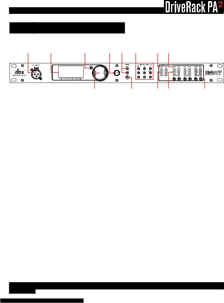
1. |
RTA MIC INPUT |
|
4 |
|
|
7 |
9 |
11 |
13 |
|
|
|
|
|
|
|
|
Connect the dbx RTA-M measurement microphone (sold separately) to this balanced XLR input jack for easy calibration of your sound system using the built-in Wizards. Or use the RTA for manual adjustments and system troubleshooting. This jack supplies +15V phantom power.
2. LCD Display
This LED backlit LCD display provides the visual feedback required for operating the PA2 processor from the front panel.
3. BACK Button
Pressing this button will navigate back one level in the current menu tree. Pressing this button multiple times will navigate back to the Home screen.
4. DATA Wheel (SELECT)
This data wheel is used for scrolling and loading presets, scrolling menus, selecting on-screen options and parameters, and editing selected on-screen options and parameters. Some functions are performed by turning the data wheel and others are performed by pressing the data wheel.
5. WIZARD Button
Pressing this button enters the Wizard menu, where you can select a specific Wizard to run or run all Wizards in succession. For more information on the different Wizards, see ‘Using The Wizards’ on page 14.
6. PRESET Buttons
The STORE and RECALL buttons are used to store and recall presets. For more information on storing, copying, and recalling presets, see ‘Managing Presets’ on page 25.
7. UTILITY Button
Pressing this button enters the Utility menu, where you can get information about the PA2’s firmware and network settings and configure global system settings which dictate how the PA2 operates. See ‘Utility’ on page 46 for information on the options and parameters available in the Utility menu.
8. INSTANT ACCESS Buttons
Pressing each of these buttons opens the menu for the corresponding processing module, where you can edit the parameters pertaining to each processing module. Pressing the RTA button enters the Real-Time Analyzer, where you can monitor the system’s signal using the optional dbx RTA-M microphone for fine-tuning and troubleshooting the system.
4

®
9. INPUT Meters
These 6-segment LED meters display the input signal level strength and available headroom, and range from SIG (signal present) to 0 (dBFS). These meters monitor the signal level right after the A/D converter and will light when the signal level is greater than or equal to the values shown in the table to the right.
Input LEDs |
dBFS |
(switch set to +4 dBu) |
(switch set to -10 dBV) |
0 |
-0.1 |
19.9 dBu |
7.7 dBV |
|
|
|
|
3 |
-3 |
17 dBu |
4.8 dBV |
|
|
|
|
10 |
-10 |
10 dBu |
-2.2 dBV |
|
|
|
|
15 |
-20 |
5 dBu |
-7.2 dBV |
|
|
|
|
20 |
-30 |
0 dBu |
-12.2 dBV |
|
|
|
|
SIG |
-48 |
-28 dBu |
-40.2 dBV |
|
|
|
|
10. CLIP LEDs
When these LEDs light, it indicates that the PA2’s inputs are being overdriven and input clipping is occurring. These LEDs feature a peak hold function, so they will remain lit for a short period of time after the signal level drops back below the clip point. The dbx Type IV™ conversion system built into the PA2 will clamp down on excessively loud input signals and prevent the A/D converters from clipping. If you’re lighting these LEDs, you will need to reduce the output level of your mixer. If you have the +4dBu/-10dBV switch on the back panel of the PA2 set to the -10dBV position, but you’re sending a +4dBu signal to the PA2’s inputs, this may cause these LEDs to light prematurely. If this occurs, set this switch to the +4dBu position (mute the PA2’s outputs before doing so).
11. OUTPUT Meters
These 6-segment LED meters display the output signal level strength and available headroom, and range from SIG (signal present) to 0 (dBFS). These meters monitor the signal level after the limiter modules and output MUTE buttons and will light when the signal level is greater than or equal to the values shown in the table to the right.
Output LEDs |
dBFS |
dBu |
|
|
|
0 |
-0.1 |
19.9 |
|
|
|
3 |
-3 |
17 |
|
|
|
10 |
-10 |
10 |
|
|
|
15 |
-15 |
5 |
|
|
|
20 |
-20 |
0 |
|
|
|
SIG |
-48 |
-28 |
|
|
|
12. TH (THRESHOLD) Meters
These multi-colored threshold LEDs indicate output limiter activity within the specified output channels. The three colored states are:
•Green
The signal level is under threshold.
•Yellow
The signal level has approached the threshold and some minor limiting is occurring. This state is only active when the limiter’s OverEasy™ setting is turned on.
•Red
The signal level has exceeded the limiter’s threshold and limiting is occurring.
13.MUTE Buttons
Pressing each of these buttons will mute the corresponding output channel. When activated, the signal will be muted prior to the output meter. The state of these outputs are global and are not stored to presets. However, the state of these buttons will be retained after a power cycle. The MUTES POWERUP function, available in the Utility menu, lets you configure the PA2 to always power on with all outputs muted. See ‘Utility’ on page 46 for more information on this feature. You can also press and hold any of these MUTE buttons upon power up to force the PA2 to initialize with all outputs muted. See ‘Initialize With Mutes On’ on page 47 for more information on this feature.
5
®
Rear Panel
1 |
4 |
5 |
120V |
50/60Hz |
2 |
3 |
6 |
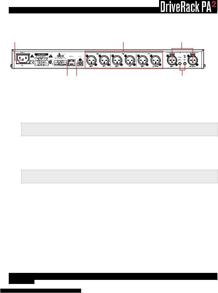
1. IEC AC Power Inlet
Connect the included IEC power cord to this power inlet. The DriveRack PA2 ships from the factory configured for one of two specified power voltage ranges, they are:
•100-120V, 50Hz/60Hz
•220-240V, 50Hz/60Hz
Note: Ensure the screening under this outlet matches the voltage specification in your country before applying power to the PA2.
2. Ethernet Port
This RJ45 connector is used for updating the firmware and controlling the PA2 from a networked device using the free DriveRack PA2 control app. See ‘Network Connections’ on page 9 and ‘Networking’ on page 57 for more information.
Note: A DHCP enabled switch or Wi-Fi router is required to assign an IP address to the PA2 for network control.
3. USB Port
This USB connector is used for updating the PA2’s firmware. See ‘Firmware Updates’ on page 59 for more information.
4. Outputs 1-6
These six electronically balanced XLR outputs correspond to the low, mid, and high processing modules in the PA2’s output processing section. Crossover frequency points can be extended to overlap each other in the crossover processing module, allowing multiple outputs to be configured for full range operation if required.
5. Inputs 1-2
Connect your mixer to these electronically balanced XLR connectors. These inputs can be configured for stereo or mono applications in the Wizard. The input sensitivity of these jacks are affected by the +4dBu/-10dBV switch.
6
®
6. Input Switches
These switches are recessed to prevent accidental switching. You may need to use the tip of your fingernail or an object with a pointy tip, such as a pen, to activate these switches.
•+4dBu/-10dBv Switch
This switch sets the PA2’s input sensitivity. Select the +4dBu option (switch out) when connecting a mixer or device which has a nominal output operating level of around +4dBu. Select the -10dBV option (switch in) when connecting a mixer or device which operates at a lower “consumer” level, such as some DJ mixers or a consumer device with unbalanced output connectors (such as RCA connectors). If you’re not sure what the nominal output operating level of your mixer is, check the product’s manual or contact the manufacturer. It’s advisable to only switch this switch when your amplifiers are powered off or the DriveRack PA2’s outputs are muted.
•Ground Lift Switch
The ground lift switch lifts the pin 1 chassis ground on both input XLR connectors. In most applications, this switch should be left in the out (disabled) position. If hum becomes an issue and is caused from a ground loop between your mixer and PA2, try engaging this switch. It’s advisable to only switch this switch when your amplifiers are powered off or the DriveRack PA2’s outputs are muted.
7

®
Installing
 The DriveRack PA2
Installation Recommendations
FOR RACK MOUNT USE ONLY. Install the PA2 in your 19” rack with the provided rack screws. When installed in a rack, make sure there is proper ventilation. The sides and back of the device should be free of any obstruction that would prevent airflow. The PA2 should not be mounted above or below anything that generates excessive heat. Ambient temperatures should not exceed 950 F (350 C) when equipment is in use. Although the unit is shielded against radio frequency and electromagnetic interference, extremely high fields of RF and EMI should be avoided where possible.
Making Connections
Audio Connections
1.Ensure the power is turned off on all interconnecting equipment and the PA2 before making audio connections.
2.See ‘Application Guide’ on page 50 for application notes and system diagrams which can be used for reference when connecting the PA2 to your system. See ‘Cable Diagrams’ on page 61 for information on cabling.
3.Connect the outputs of your mixing console to the inputs of the PA2.
Note: The +4dBu/-10dBV switch on the back panel of the PA2 must be set to the correct position for your application in order to avoid performance issues. +4dBu is referred to as “pro level” and will be the correct setting for most applications, as most pro and semi-pro mixers will output a nominal level of around +4dBu. -10dBV is referred to as “consumer level” and will need to be used when connecting a source which has an output level approximately 12 dB lower than pro level equipment.
4.Connect the PA2’s outputs to the designated amplifier or powered speaker inputs.
5.If you plan to calibrate the system using the built-in Wizards, connect the optional dbx RTA-M measurement microphone using a microphone cable of suitable length and place it in a microphone stand.
8
®
Network Connections
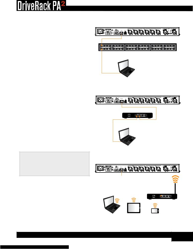
1.Download and install the free DriveRack PA2 control app from the iTunes® Store, the Android® Market, or from www. dbxpro.com.
2.Connect a straight-through CAT5e or CAT6 Ethernet cable (sold separately) to the Ethernet port on the DriveRack PA2.
3.Connect the other end of the Ethernet cable to one of the LAN ports on a DHCP (Dynamic Host Configuration Protocol) enabled network router or switch.
4.For a wired connection, connect your computer’s Ethernet port to one of the other LAN ports on the router or switch using a straight-through CAT5e or CAT6 cable.
5.If using a Wi-Fi router, connect to the Wi-Fi network using your Wi-Fi equipped computer or device.
6.After applying power, you can ensure the PA2 has been assigned an IP address by pressing the UTILITY button then selecting the SYSTEM INFO option.
Note: A DHCP enabled switch or router must be used to assign an IP address to the DriveRack PA2. See ‘Networking’ on page 57 for more information on controlling the PA2 over a network.
Wired Ethernet Switch
DriveRack PA2
120V |
50/60Hz |
Ethernet Switch With DHCP Enabled
Mac® or Windows®
Computer
Wired Ethernet Router
DriveRack PA2
120V |
50/60Hz |
Ethernet Router With DHCP Enabled
1 |
2 |
3 |
4 |
WAN |
LAN |
Mac® or Windows®
Computer
Wi-Fi Router
DriveRack PA2
120V |
50/60Hz |
|
2 |
3 |
4 |
WAN |
|
LAN |
|
Wi-Fi Router With DHCP Enabled
|
or |
or |
Mac® or Windows® |
Android® or iOS® |
Android® or iOS® |
Computer With Wi-Fi |
Tablet |
Smartphone |
9

®
Applying Power
1.Ensure your power amplifiers or powered speakers are turned off.
2.Make sure that the included IEC power cable provided with your PA2 has the proper connector for connection to your AC power outlet and that the power screening under the IEC power inlet on the back panel of the PA2 matches your country’s voltage requirements.
3.Connect the power cable to the AC power inlet on the PA2’s back panel.
4.Apply power to the PA2 by connecting the other end to an available AC power outlet. Since the PA2 does not have a power switch, an AC power strip or power conditioner can be used for switching power to the PA2 on and off.
5.Apply power to your mixer then your power amplifiers or powered speakers.
Note: When powering up a fully configured and connected PA system, it is advisable to ALWAYS turn on the mixer and PA2 first then turn on your amplifiers or powered speakers. It’s also a good idea to ensure you’re not passing audio to the mixer’s outputs (or ensure your mixer’s master faders are all the way down) before applying power to the amplifiers. When powering down the system, you should ALWAYS power down the amplifiers first, wait about 10 seconds to allow them to discharge, then power down the mixer and PA2. In other words, every time you use your system, the power amps should be the last components turned on and the first components turned off.
10

®
Getting Started
Menu Navigation Overview
The DriveRack PA2’s user interface was carefully designed to provide logical navigation and avoid deeply nested menus. The menu navigation is laid out as shown in the below diagram.
|
HOME MODE |
|
|
Con guration |
|
|
Home Screen |
|
SELECT |
Dynamic Meters |
|
Home Screen |
||
|
||
Press |
RTA |
|
Home Screen |
||
|
||
|
System Info |
|
|
Home Screen |
Press RTA Button
Press RECALL Button
Press STORE Button
Press UTILITY Button
Press GEQ Button
Press AFS Button
Press SUB Button
Press COMP Button
Press XOVER Button
Press LIMITER Button
Press PEQ Button
Press DELAY Button
Press WIZARD Button
RTA Menu
Preset Recall Menu
Preset Store Menu
Utility Menu
Graphic EQ Menu
AFS Menu
Subharmonics Menu
Compressor Menu
Crossover Menu
Limiter Menu
Parametric EQ Menu
Delay Menu
Wizard Menu
Turn DATA Wheel / Press SELECT
Turn DATA Wheel / Press SELECT
Turn DATA Wheel / Press SELECT
Turn DATA Wheel / Press SELECT
Turn DATA Wheel / Press SELECT
Turn DATA Wheel / Press SELECT
Turn DATA Wheel / Press SELECT
Turn DATA Wheel / Press SELECT
Turn DATA Wheel / Press SELECT
Turn DATA Wheel / Press SELECT
Turn DATA Wheel / Press SELECT
Turn DATA Wheel / Press SELECT
Turn DATA Wheel / Press SELECT
Turn DATA Wheel / Press SELECT
Turn DATA Wheel / Press SELECT
Turn DATA Wheel / Press SELECT
Turn DATA Wheel / Press SELECT
Turn DATA Wheel / Press SELECT
High Crossover Menu
Mid Crossover Menu
Low Crossover Menu
High Limiter Menu
Mid Limiter Menu
Low Limiter Menu
AutoEQ Menu
High PEQ Menu
Mid PEQ Menu
Low PEQ Menu
High Limiter Menu
Mid Limiter Menu
Low Limiter Menu
Run All Wizards
Run Setup Wizard
Run AutoEQ/
Level Assist
Run AFS Wizard
Wizard Options
DELAYButton
HoldHold& Press& PressLIMITER ButtonHold & HoldPress& PressXOVER ButtonPEQButton
11

®
Operating Modes Explained
This section describes the different operating modes available in the DriveRack PA2 and how to enter each mode.
Home Mode
This is the default operating mode. It is the mode the DriveRack PA2 enters when it initially boots and is the mode which displays the selected Home screen. From any menu, you can get back to Home mode by repeatedly pressing the BACK button. How many times you must press the BACK button to return to Home mode is determined by how deeply you have navigated in the current menu.
Wizard Mode
This mode is entered by pressing the WIZARD button. This mode is used to create a new system configuration or edit an existing one. When running the Wizards, pressing and holding the WIZARD button will abort the Wizard and return to the main Wizard menu.
Edit Mode
Edit mode is entered by pressing any of the INSTANT ACCESS buttons or the UTILITY button. This mode is used to edit processing module parameters, RTA parameters, and global system parameters.
Preset Recall Mode
This mode is entered by pressing the preset RECALL button and is used to load an existing factory or user preset.
Preset Store Mode
This mode is entered by pressing the preset STORE button and is used to store the current preset to a user preset memory location.
12
®
The Home Screens
The Home screen is the first screen which appears in the LCD display after the DriveRack PA2 fully initializes (this is also referred to as “Home mode”). There are four Home screens to choose from, providing the instant visual feedback you need, when you need it. All Home screens will display the currently loaded preset number and name, so you always know which preset is currently loaded. To toggle between Home screens, simply press the DATA WHEEL from Home mode. Below is a description of each available Home screen.
Configuration Home Screen
This is the default Home screen. This screen shows the configuration and signal flow of the currently loaded preset. The far left of the screen indicates input configuration. The far right of the screen indicates output configuration. All the blocks in-between represent the processing modules.
1 |
E |
|
USER |
Preset 1 |
|
|
R |
|
|
QSBPYV |
|
|
EFUMLO |
LH |
L GAASCD XPL D RH |
||
R |
|
LM |
|
PL D RM |
|
MIC |
RTA |
PL D LL |
|
|
RL |
Dynamics Meter Home Screen
This Home screen shows dynamic processing activity in the input compressor and output limiter modules. The meters on the left of this screen show threshold activity. The


 icon indicates the signal is below threshold and no dynamics processing is occurring. The
  O
O  icon indicates that the signal level is within the “OverEasy™” region and some minor compression or limiting is beginning to occur (this icon will only light if the dynamics processor is configured for “OverEasy” operation). The

 icon indicates that the signal is over threshold and full compression or limiting is occurring. The meters on the right show how much gain reduction is occurring in each processing module.
RTA Home Screen
This Home screen provides quick access to the Real-Time Analyzer. When the optional dbx RTA-M measurement microphone is connected to the RTA Mic Input, this RTA can be used for manually fine-tuning and troubleshooting the system.
System Info Home Screen
This Home screen shows the currently installed firmware version and the IP address assigned to the PA2.
Configuration Home Screen
EDIT1 Preset 1
|
|
|
O |
|
|
|
COMPRESSOR |
30 |
12 |
5 |
|
|
|
|
|||||||||||
|
|
|
O |
|
|
|
HIGH LIMITER |
0 |
||||
|
|
|
|
|
|
|
|
|
|
|
||
|
|
|
|
|
|
|
|
|
|
|
||
|
|
|
O |
|
|
|
MID LIMITER |
|
|
|
|
|
|
|
|
|
|
||||||||
|
|
|
|
|
||||||||
|
|
|
O |
|
|
|
LOW LIMITER |
|
|
|
|
|
|
|
|
|
|
||||||||
|
|
|
|
|
|
|
|
|
|
|
||
|
|
|
|
|
|
|
|
|
|
|
||
|
|
|
|
|
|
|
|
|
|
|
|
|
Dynamics Meter Home Screen
EDIT1 Preset 1
RTA
RTA Home Screen
USER1 Preset 1
Version: 1.1.3.0
IP: 192.168.0.2
System Info Home Screen
Note: After a power cycle, the DriveRack PA2 will return to the Home screen selected before the unit was powered down.
Note: The TIME OUT feature in the Utility menu will determine if the DriveRack PA2 will return to the Home screen after a period of inactivity and how long it will wait before timing out. See ‘Utility’ on page 46 for further information on the TIME OUT feature.
13

®
Configuring The DriveRack PA2
This section of the manual describes how to configure the DriveRack PA2 for your application. The easiest way to configure the PA2 is to use the built-in Wizards. However, for the veteran sound engineers and DriveRack power users, the PA2 can also be configured and tweaked manually. Power users can create the basic configuration using the Setup Wizard, or load an existing preset, then tweak the parameters as necessary from there. The RTA can be used to analyze the system’s frequency response and make manual adjustments or for troubleshooting system issues.
Using The Wizards
The PA2 Wizards are accessed by pressing the WIZARD button. These Wizards walk you through the configuration process with simple, step-by-step instructions, making it easy to configure the PA2 for your amplifiers, speakers, and the venue.
Using the optional dbx RTA-M measurement microphone, the Wizards can optimize your sound system by helping adjust your left/right speaker balance, low/mid/high level balance, and analyzing your room and applying accurate room EQ – in a fraction of the time it would take to manually analyze and calibrate the system.
The updated DriveRack PA2 Wizard section now also includes options for altering existing configurations (presets), making it possible to use the Wizards to update portions of a configuration without having to recreate the whole configuration from scratch. Below is a list and description of each of the available options in the PA2’s Wizard menu.
RUN ALL WIZARDS [CURRENT SETTINGS, NEW SETTINGS]
Select this option to run through all the Wizards in succession. Select the NEW SETTINGS option to default all the Wizard settings and configure a new system from scratch. Select the CURRENT SETTINGS option to alter an existing configuration or to view the selections made when the preset was configured – note that you can only view these settings if the currently loaded preset was created using the Setup Wizard.
RUN SETUP WIZARD
This Wizard allows you to enter your speaker and amplifier models and automatically sets the crossover, output parametric EQ, driver alignment delay, polarity, and limiter settings. The Setup Wizard in the PA2 now stores all selections made with the preset. So if you load a preset that was created using the Setup Wizard, all the selections made during creation can be viewed at any time by entering the Setup Wizard. The available options in this menu are:
•RUN ALL SETUP
Select this option to run through the entire Setup Wizard (which consists of all Setup Wizard items listed below).
•RUN INPUT SETUP [MONO, STEREO]
Select this option to switch the input configuration between mono and stereo.
•RUN GEQ SETUP [DUAL MONO, STEREO LINKED]
Select this option to switch the GEQ configuration between dual mono and stereo linked.
•RUN SPEAKER/AMP SETUP
Select this option to update speaker and/or amp selections (tunings).
14
®
RUN AutoEQ/LEVEL ASSIST
When used with the optional dbx RTA-M measurement microphone, this Wizard helps you balance the left/right speaker levels, the low/mid/high speaker levels (for 2-way and 3-way systems), and automatically equalizes the speakers to the current room environment. After selecting this option, you can select whether you would like to run both the Level Assist and AutoEQ functions, Level Assist only, or AutoEQ only.
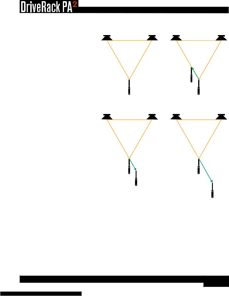
The diagrams to the right show the recommended Level Assist and AutoEQ RTA-M mic positions. When running AutoEQ, you will be prompted to select how many mic positions you would like AutoEQ to analyze – the selections are: 2, 3, or 4.
Level Assist/AutoEQ Mic Position 1 |
|
AutoEQ Mic Position 2 |
||||||
Left Speaker |
Right Speaker |
Left Speaker |
|
|
|
Right Speaker |
||
|
|
|
|
|
|
|
|
|
|
|
|
|
|
|
|
|
|
|
Speakers & Mic Form an |
|
/rd |
|
/rd |
|
/rd |
|
|
|
|
|
|
|
|
|
|
|
Equilateral Triangle |
|
|
|
|
|
|
|
|
|
|
|
|
/ |
||
|
|
|
|
|
rd |
||
|
|
|
RTA-M Mic |
|
|
|
|
|
|
|
|
|
|
|
|
|
|
|
Placement 2 |
|
|
|
|
|
|
RTA-M Mic |
|
|
|
|
RTA-M Mic |
|
|
|
|
|
|
||
|
|
Placement 1 |
|
|
|
|
Placement 1 |
|
|
|
|
|
|
|
Reference |
AutoEQ Mic Position 3 (Optional) |
AutoEQ Mic Position 4 (Optional) |
||||||
Left Speaker |
|
Right Speaker |
Left Speaker |
|
|
|
Right Speaker |
The Level Assist and AutoEQ mic position 1 measurements should be taken with the microphone placed out in front of
the speakers the same distance as the speakers are apart, so that the three components form an equilateral triangle, as shown in the Level Assist/AutoEQ Mic Position 1 diagram.
|
|
|
|
|
|
|
/rd |
/rd |
/rd |
|
/rd |
/rd |
/rd |
/
rd
/
Each time you move the RTA-M mic |
rds |
position it should move approximately
1/3rd the distance the speakers are apart from the initial “RTA-M Mic Placement 1
Reference”, as shown in the AutoEQ Mic Position 2-3 diagrams. Mic position 4 is the
exception as it should be placed 2/3rds the distance from the RTA-M Mic Placement 1 Reference. For example, if your speakers were 20 feet apart, you would move the microphone approximately 7’ (20 * (1/3) = 6.6) from the RTA-M Mic Placement 1 Reference for mic positions 2-3 and approximately 14’ from the RTA-M Mic Placement 1 Reference for mic position 4. However, as a general rule of thumb and for the sake of simplicity, a distance of 5’ should work well for most venues. If the recommended placement of the mic in positions 2-4 is not possible, just place the mic in a position that differs from the other measurement positions.
RUN AFS WIZARD
This Wizard walks you through the process of ringing out the system to provide higher system gain before feedback. This is accomplished by pushing your system into feedback so AFS can detect the initial frequencies which cause feedback and notch them using Fixed filters. When the AFS Wizard is complete, it will automatically enable the Live filters, for automated protection during system use.
15

®
WIZARD OPTIONS
The available options in this menu are:
•AutoEQ TARGET [RECOMMENDED PA CURVE, FLAT]
When a sound system’s frequency response is flattened, it can sound a bit thin on the bottom end. The AutoEQ TARGET option makes up for this by adding a bass boost. Select the RECOMMENDED PA CURVE option (this is the default setting) to allow AutoEQ to automatically enhance the low end. Select the FLAT option if you want the system to be tuned flat when running the AutoEQ Wizard.
•LEVEL ASSIST AUTO TRIM [ON, OFF]
When this option is turned on, Level Assist will automatically make fine level adjustments under the hood for any system level mismatches which are 3 dB or less. When this option is turned off, no automatic level adjustments will be made by Level Assist and all system level mismatches will need to be adjusted using the amplifier attenuators until they are within a 1 dB tolerance.
Note: Level adjustments made by the LEVEL ASSIST AUTO TRIM function cannot be seen or edited. To clear them you must turn the LEVEL ASSIST AUTO TRIM function off then re-run Level Assist in the Wizard menu.
•MIC RESPONSE [dbx RTA-M, FLAT]
When the dbx RTA-M option is selected, AutoEQ will automatically compensate for the frequency response of the dbx RTA-M microphone, providing more accurate AutoEQ results. Select the FLAT option if using a measurement microphone other than the dbx RTA-M.
•SETUP AUTO NAMING [ON, OFF]
When this option is on, the PA2 will automatically name presets based on the speaker selections made in the Setup Wizard
– the automatically generated preset name can still be edited when storing the preset if desired.
To use the Wizards to configure a new system:
1.Press the WIZARD button.
2.Select the RUN ALL WIZARDS option using the DATA wheel.
3.Select the NEW SETTINGS option by turning the DATA wheel. Press the DATA wheel to confirm your selection.
4.Follow the on-screen instructions. Turn the DATA wheel to edit on-screen selections and press the DATA wheel to confirm on-screen selections.
Note: Pressing and holding the WIZARD button at any time during the Wizard procedure will exit the current Wizard and return to the main Wizard menu.
16
®
About Speaker & Amplifier Tunings
The PA2 has a Setup Wizard to help you configure your sound system. When you run the Setup Wizard, it will ask you to select the make and model of your speakers and amplifiers from a list of available options, referred to as “tunings”. There are speaker tunings and amplifier tunings. When you select your speakers from the tuning list, the PA2 will automatically configure the crossover, output PEQs, polarity, and in some cases, driver alignment delays. When you select your amplifiers from the tuning list, the PA2 will automatically set your output gains (located in the crossover) and limiter threshold settings.
The PA2 includes a variety of speaker and amplifier tunings from JBL®, Crown®, and more. If your particular tunings are not available in the PA2’s preset tuning list, you can use the DriveRack PA2 control app to access the online database where you can find additional tunings. If you can’t find tunings for your particular speakers or amplifiers, you will need to select the NOT LISTED option in the PA2’s Setup Wizard. The PA2 will automatically set usable default settings which may sound and work just fine, however, you may wish to manually calibrate the PA2 in order to realize the full potential of your sound system and ensure your loudspeakers are protected. Providing full details on how to manually calibrate a sound system is beyond the scope of this manual, but there is an abundance of free information available on the internet which covers these topics. This section of the manual will cover some of the basics to help get you started.
Loudspeaker manufacturers perform extensive testing on their products and will often provide much of the data necessary to optimize their loudspeaker systems. Check your speaker manufacturer’s website or contact them directly to see if they can provide a speaker tuning data sheet that you can use for manually entering speaker tuning parameters into the PA2. These tuning data sheets will typically include recommended crossover, polarity, driver alignment delay, and sometimes, parametric EQ settings.
17
 Loading...