


PA+
Professional Audio Equipment
WARNING FOR YOUR PROTECTION
READ THE FOLLOWING:
KEEP THESE INSTRUCTIONS
HEED ALL WARNINGS
FOLLOW ALL INSTRUCTIONS
THE APPARATUS SHALL NOT BE EXPOSED TO DRIPPING OR SPLASHING
LIQUID AND NO OBJECT FILLED WITHI LIQUID, SUCH AS VASES, SHALL
BE PLACED ON THE APPARATUS.
CLEAN ONLY WITH A DRY CLOTH.
DO NOT BLOCK ANY OF THE VENTILATION OPENINGS. INSTALL IN AC-
CORDANCE WITH THE MANUFACTURER’S INSTRUCTIONS.
DO NOT INSTALL NEAR ANY HEAT SOURCES SUCH AS RADIATORS,
HEAT REGISTERS, STOVES, OR OTHER APPARATUS (INCLUDING AMPLI-
FIERS) THAT PRODUCE HEAT.
ONLY USE ATTACHMENTS/ACCESSORIES SPECIFIED BY THE MANUFAC-
TURER.
UNPLUG THIS APPARATUS DURING LIGHTNING STORMS OR WHEN
UNUSED FOR LONG PERIODS OF TIME.
Do not defeat the safety purpose of the polarized or grounding-type plug. A
polarized plug has two blades with one wider than the other. A grounding
type plug has two blades and a third grounding prong. The wide blade or third
prong are provided for your safety. If the provided plug does not fit your out-
let, consult an electrician for replacement of the obsolete outlet.
Protect the power cord from being walked on or pinched particularly at plugs,
convenience receptacles, and the point where they exit from the apparatus.
Use only with the cart stand, tripod bracket, or table specified by the manufac-
ture, or sold with the apparatus. When a cart is used, use caution when moving
the cart/apparatus combination to avoid injury from tip-over.
Refer all servicing to qualified service personnel. Servicing is required when
the apparatus has been damaged in any way, such as power-supply cord or plug
is damaged, liquid has been spilled or objects have fallen into the apparatus, the
apparatus has been exposed to rain or moisture, does not operate normally, or
has been dropped.
POWER ON/OFF SWITCH: If the equipment has a Power switch, the Power
switch used in this piece of equipment DOES NOT break the connection from
the mains.
MAINS DISCONNECT: The plug shall remain readily operable. For rack-
mount or installation where plug is not accessible, an all-pole mains switch with
a contact separation of at least 3 mm in each pole shall be incorporated into
the electrical installation of the rack or building.
FOR UNITS EQUIPPED WITH EXTERNALLY ACCESSIBLE FUSE RECEP-
TACLE: Replace fuse with same type and rating only.
MULTIPLE-INPUT VOLTAGE: This equipment may require the use of a different
line cord, attachment plug, or both, depending on the available power source at
installation. Connect this equipment only to the power source indicated on the
equipment rear panel. To reduce the risk of fire or electric shock, refer servic-
ing to qualified service personnel or equivalent.
If connected to 240V supply, a suitable CSA/UL certified power cord shall be
used for this supply.
Safety InStructIonS
NOTICE FOR CUSTOMERS IF YOUR UNIT IS EQUIPPED WITH A POWER CORD.
WARNING: THIS APPLIANCE SHALL BE CONNECTED TO A MAINS SOCKET OUTLET WITH A
PROTECTIVE EARTHING CONNECTION.
The cores in the mains lead are coloured in accordance with the following code:
GREEN and YELLOW - Earth BLUE - Neutral BROWN - Live
As colours of the cores in the mains lead of this appliance may not correspond with the coloured
markings identifying the terminals in your plug, proceed as follows:
•
The core which is coloured green and yellow must be connected to the terminal in the plug
marked with the letter E, or with the earth symbol, or coloured green, or green and yellow.
•
The core which is coloured blue must be connected to the terminal marked N or coloured
black.
•
The core which is coloured brown must be connected to the terminal marked L or coloured
red.
This equipment may require the use of a different line cord, attachment plug, or both, depending
on the available power source at installation. If the attachment plug needs to be changed, refer
servicing to qualified service personnel who should refer to the table below. The green/yellow
wire shall be connected directly to the units chassis.
CONDUCTOR
WIRE COLOR
Normal Alt
L LIVE BROWN BLACK
N NEUTRAL BLUE WHITE
E EARTH GND
GREEN/
YEL
GREEN
WARNING: If the ground is defeated, certain fault conditions in the unit or in the system to
which it is connected can result in full line voltage between chassis and earth ground. Severe
injury or death can then result if the chassis and earth ground are touched simultaneously.
The symbols shown above are internationally accepted symbols that warn of
potential hazards with electrical products. The lightning flash with arrowpoint in
an equilateral triangle means that there are dangerous voltages present within
the unit. The exclamation point in an equilateral triangle indicates that it is
necessary for the user to refer to the owner’s manual.
These symbols warn that there are no user serviceable parts inside the unit.
Do not open the unit. Do not attempt to service the unit yourself. Refer all
servicing to qualified personnel. Opening the chassis for any reason will void
the manufacturer’s warranty. Do not get the unit wet. If liquid is spilled on the
unit, shut it off immediately and take it to a dealer for service. Disconnect the
unit during storms to prevent damage.
IMPORTANT SAFETY INFORMATION

DecLaratIon of
conforMIty
Manufacturer’s Name: dbx Professional Products
Manufacturer’s Address: 8760 S. Sandy Parkway
Sandy, Utah 84070, USA
declares that the product:
Product name: dbx DriveRack PA +
Note: Product name may be suffixed by the EU.
Product option: None
conforms to the following Product Specifications:
Safety: IEC 60065 -01+Amd 1
EMC: EN 55022:2006
EN 55024:1998
FCC Part 15
Supplementary Information:
The product herewith complies with the requirements of the:
Low Voltage Directive 2006/95/EC
EMC Directive 2004/108/EC.
RoHS Directive 2002/95/EC
WEEE Directive 2002/96/EC
With regard to Directive 2005/32/EC and EC Regulation
1275/2008 of 17 December 2008, this product is designed,
produced, and classified as Professional Audio Equipment and
thus is exempt from this Directive.
Vice President of Engineering
8760 S. Sandy Parkway
Sandy, Utah 84070, USA
Date: March 19, 2010
European Contact: Your local dbx Sales and Service Office or
Harman Music Group
8760 South Sandy Parkway
Sandy, Utah 84070, USA
Ph: (801) 566-8800
Fax: (801) 568-7583
eLectroMaGnetIc
coMPatIBILIty
This device complies with part 15 of the FCC Rules and the Product
Specifications noted on the Declaration of Conformity. Operation is
subject to the following two conditions:
this device may not cause harmful •
interference, and
this device must accept any interference received, including interfer-•
ence that may cause undesired operation.
Operation of this unit within significant
electromagnetic fields should be avoided.
use only shielded interconnecting cables.•
u.K. MaInS PLuG WarnInG
A molded mains plug that has been cut off from the cord is unsafe.
Discard the mains plug at a suitable disposal facility.
NEVER UNDER ANY CIRCUMSTANCES SHOULD YOU
INSERT A DAMAGED OR CUT MAINS PLUG INTO A 13
AMP POWER SOCKET.
Do not use the mains plug without the fuse cover in place.
Replacement fuse covers can be obtained from your local retailer.
Replacement fuses are 13 amps and MUST be ASTA approved to
BS1362.
If you want to dispose this product, do not mix it with general household w aste. There is a
separate collection system for used electronic products in accordance with legislation that
requires proper treatment, recovery and recycling.
Private household in the 25 member states of the EU, in Switzerland and Norway may return their used
electronic products free of charge to designated collection facilities or to a retailer (if you purchase a similar
new one).
For Countries not mentioned above, please contact your local authorities for a correct method of disposal.
By doing so you will ensure that your disposed product undergoes the necessary treatment, recovery and
recycling and thus prevent potential negative effects on the environment and human health.
IMPORTANT SAFETY INFORMATION

Section 1- Introduction .......................... 1
1.1 Defining the DriveRack PA+ ............. 1
1.2 Service Contact Info ....................... 2
1.3 Warranty ....................................... 3
Section 2- Getting Started ...................... 4
2.1 Rear Panel Connections .................. 4
2.2 Front Panel Connections ................. 5
2.3 Installation Steps .......................... 6
2.4 Quick Start ................................... 6
Section 3 - Editing Functions .................. 8
3.1 Basic Navigation Modes .................. 8
3.2 Button Array Overview .................... 8
3.3 Navigating the EQ Section .............. 10
3.4 Navigating the Subharmonic Section 10
3.5 Navigating the Crossover Section ..... 11
3.6 Navigating the AFS (Advanced Feedback
Suppression) Section ...................... 11
3.7 Navigating the Comp/Limiter Section 12
3.8 Navigating the Delay Section........... 12
3.9 Navigating the Utility Section ......... 13
3.10 Navigating the Wizard Section ....... 13
Section 4 - Operating Functions ............... 14
4.1 Preset Definition ........................... 14
4.2 Navigating Factory Presets .............. 14
4.3 Editing Factory Presets ................... 15
4.4 Saving Presets ............................... 15
Section 5 - Detailed Parameters ............... 17
5.1 Graphic EQ .................................... 17
5.2 Advanced Feedback Suppression....... 17
5.3 Subharmonic Synthesizer ................ 19
5.4 Crossover ...................................... 20
5.5 Output Parametric EQ (PEQ) ............ 20
5.6 Compressor/Limiter ........................ 21
5.7 Alignment Delay ............................ 22
Section 6 - Application Guide .................. 24
6.1 Stereo 3-Way ................................. 24
6.2 Stereo 3-Way with Mono Sub ........... 25
6.3 Stereo 2-Way ................................. 26
6.4 Stereo 2-Way with Mono Sub ........... 27
Section A - Appendix ............................... 28
A.1 Factory Reset ................................ 28
A.2 DriveRack PA+ Power-Up Button
Functions ..................................... 28
A.3 Power Up Quick Key Options............ 28
A.4 Update Firmware ........................... 29
A.5 Preset List/Speaker Tunings ............ 29
A.6 Specifications ............................... 30
A.7 AUTO-EQ Optimization Tips ............. 31
A.8 Block Diagram ............................... 32
A.9 System Setup and Gain Structure ..... 33
DriveRack
®
PA+
Table of Contents

Section 1- Introduction
Drive your PA to a whole new level of performance with the DriveRack PA+ Complete
Equalization & Loudspeaker Management System. The DriveRack PA+ from dbx Professional
Products represents a complete integration of the key elements that help ensure optimal
loudspeaker system management in PA-specific applications. Capitalizing on the legendary
dbx® DriveRack technology, the DriveRack PA+ is able to provide its user with top-tier,
pro-level loudspeaker management specifications, yet still remain appealing to the
budget-conscious audiophile who requires a tried and true utilitarian workhorse. With its
all-inclusive, no-compromise design, the DriveRack PA+ has been systematically developed and
designed to grow with your system needs for years to come.
1.1 Defining the DriveRack PA+
The dbx DriveRack PA+ is the most effective way to manage all aspects of Loudspeaker
management for Public Address system applications. The DriveRack PA+ essentially becomes
the only device that you will need between your mixer and your power amps. The following
are just some of the features of the DriveRack PA+.
DriveRack PA+ features:
Setup Wizard Steps Through Speaker and Amp Selection and Levels•
Auto Level™ Wizard Balances Your System•
Auto EQ™ Wizard with 28-Band RTA Tunes Your System For The Venue•
AFS® Wizard Helps Eliminate Feedback•
Stereo Feedback Elimination with 12 feedback notch filters•
dbx 120A Sub-harmonic Synthesizer•
Classic dbx Input Compression•
JBL® Speaker and Crown® Power Amp Tunings included•
USB Firmware and Speaker Tunings Field Updatable With Harman HiQnet™ System •
Architect
Full time RTA function•
Front-Panel Output Mutes•
Pink Noise Generator (used with Auto EQ and Auto Level Wizards)•
Linked Stereo DSP Processing for ease of use•
24-Bit ADC/24-Bit DAC, >113 dB Dynamic Range•
2-Channel XLR Input and 6-Channel XLR Output•
2x2, 2x3, 2x4, 2x5, 2x6 Crossover Configurations•
Dual 28-band Graphic EQ- Linked or Dual Mono•
Stereo Multi-band Parametric EQ•
Stereo Output Limiters•
Output Alignment Delay•
Power on/off Mute Circuitry•
Front-panel RTA-M XLR input with phantom power•
25 User Programs/25 Factory Programs•
Full Graphic LCD Display•
Front Panel Input and Output Meters•
By including every form of processing necessary to drive the signal from the mixer to the
power amp, the DriveRack PA+ allows you to eliminate all other processing devices normally
found in large and cumbersome traditional Front of House rack systems of the past.
The DriveRack PA+ Loudspeaker Management System includes two balanced XLR inputs, as well
as six balanced XLR output connectors.
DriveRack
®
PA+
Section 1
Introduction
1

1.2 Service Contact Info
If you require technical support, contact dbx Technical Support. Be prepared to accurately
describe the problem. Know the serial number of your device - this is printed on a sticker
attached to the chassis. If you have not already taken the time to fill out your warranty
registration card and send it in, please do so now. You may also register online at
www.dbxpro.com.
Before you return a product to the factory for service, we recommend you refer to the manual.
Make sure you have correctly followed installation steps and operation procedures. For further
technical assistance or service, please contact our Technical Support Department at (801)
568-7660 or visit www.dbxpro.com. If you need to return a product to the factory for service,
you MUST first contact Technical Support to obtain a Return Authorization Number.
No returned products will be accepted at the factory without a Return Authorization Number.
Please refer to the Warranty information on the following page, which extends to the first
end-user. After expiration of the warranty, a reasonable charge will be made for parts, labor,
and packing if you choose to use the factory service facility. In all cases, you are responsible
for transportation charges to the factory. dbx will pay return shipping if the unit is still under
warranty.
Use the original packing material if it is available. Mark the package with the name of the
shipper and with these words in red: DELICATE INSTRUMENT, FRAGILE! Also write the Return
Authorization Number (RA#) on the outside of the box in a conspicuous location. Insure the
package properly. Ship prepaid, not collect. Do not ship parcel post.
Section 1
Introduction
2
DriveRack
®
PA+

1.3 Warranty
This warranty is valid only for the original purchaser and only in the United States.
1. The warranty registration card that accompanies this product must be mailed within 30
days after purchase date to validate this warranty. You can also register online at
www.dbxpro.com. Proof-of-purchase is considered to be the responsibility of the consumer. A
copy of the original purchase receipt must be provided for any warranty service.
2. dbx warrants this product, when bought and used solely within the U.S., to be free from
defects in materials and workmanship under normal use and service.
3. dbx liability under this warranty is limited to repairing or, at our discretion, replacing
defective materials that show evidence of defect, provided the product is returned to dbx
WITH RETURN AUTHORIZATION from the factory, where all parts and labor will be covered up
to a period of two years. A Return Authorization number must first be obtained from dbx. The
company shall not be liable for any consequential damage as a result of the product’s use in
any circuit or assembly.
4. dbx reserves the right to make changes in design or make additions to or improvements
upon this product without incurring any obligation to install the same additions or
improvements on products previously manufactured.
5. The foregoing is in lieu of all other warranties, expressed or implied, and dbx neither
assumes nor authorizes any person to assume on its behalf any obligation or liability in
connection with the sale of this product. In no event shall dbx or its dealers be liable for
special or consequential damages or from any delay in the performance of this warranty due to
causes beyond their control.
Section 1
Introduction
3
DriveRack
®
PA+
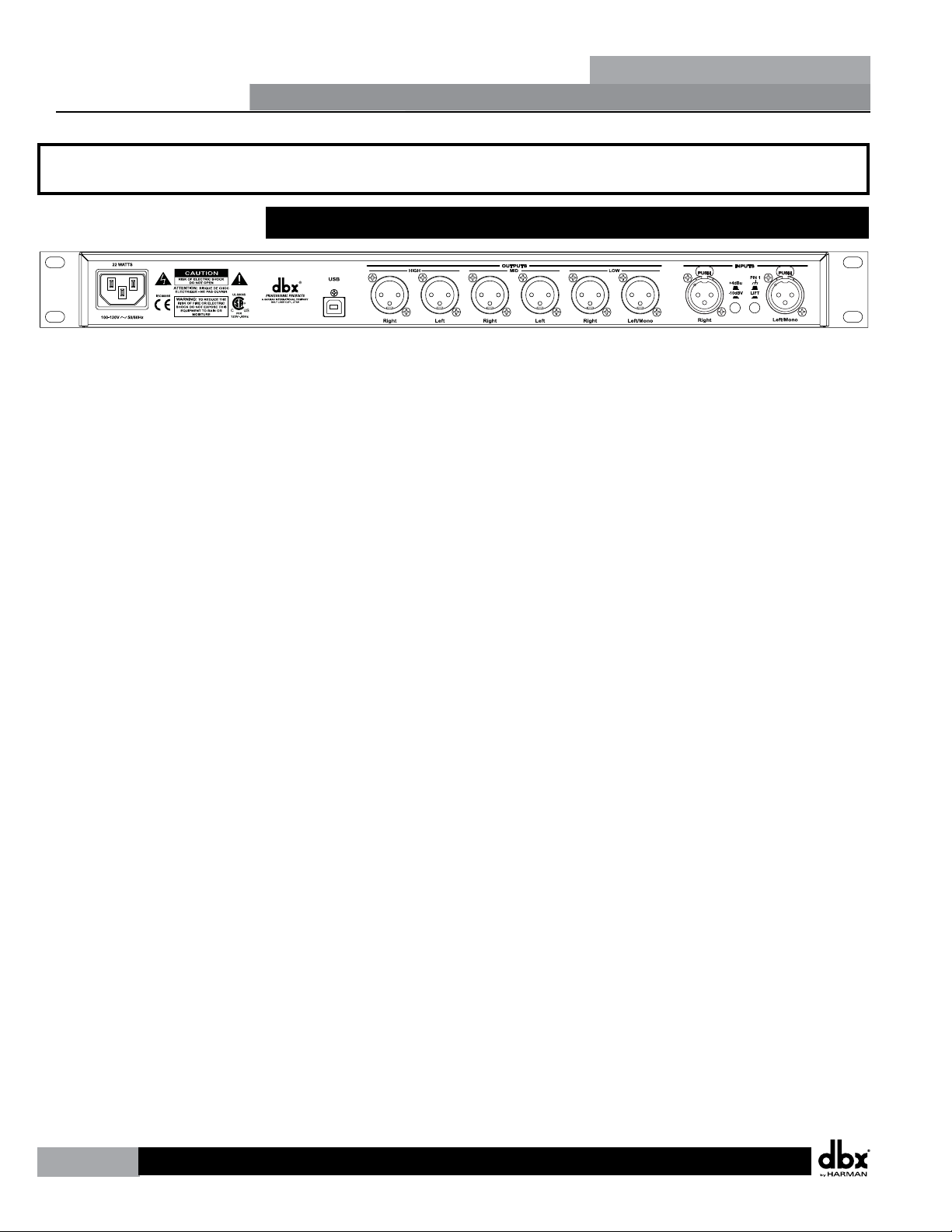
2.1 Rear Panel Connections
IEC Power Cord Receptacle
The DriveRack PA+ comes with a power supply that will accept voltages ranging from
100V-120V at frequencies from 50Hz-60Hz. An IEC cord is included. EU version accepts
220V-240V at frequencies from 50Hz-60Hz.
USB Connection
The USB connector allows users to connect the DriveRack PA+ to their computer to perform
firmware updates using HiQnet System Architect Software via System Architects Firmware
Updater. You may download HiQnet System Architect at the HiQnet Web site:
http://hiqnet.harmanpro.com/downloads.php
Outputs 1-6
The output section of the DriveRack PA+ offers six electronically balanced XLR connectors.
Inputs 1-2
The input section of the DriveRack PA+ offers two electronically balanced XLR connectors.
+4/-10dBv Switch
This switch changes the level from either +4 or -10dBv.
Ground Lift Switch
The ground lift switch lifts the pin 1 chassis ground of both input XLR connectors.
Section 2
Getting Started
4
Section 2- Getting Started
DriveRack
®
PA+
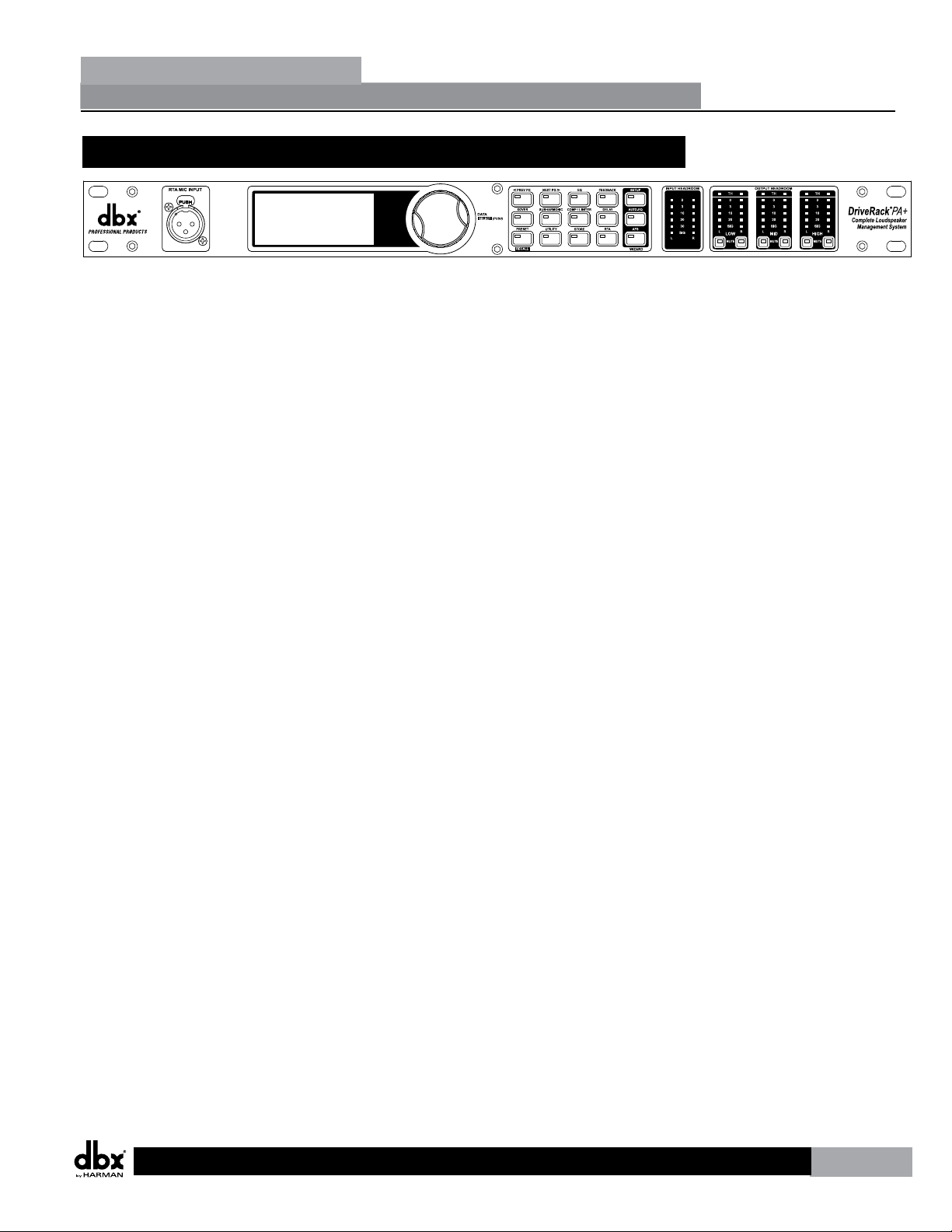
2.2 Front Panel Connections
RTA MIC Input
This balanced XLR input is used for the connection of an RTA microphone. This allows the
PA+ to measure pink noise that is sent through the speakers. The Auto-EQ Wizard can then
optimize the EQ settings for any room. You can also use the full-time RTA feature to monitor
levels and make adjustments yourself.
Data Wheel
The Data Wheel of the DriveRack PA+ is used to scroll through the preset menu, load presets,
select parameters and edit parameter values.
LCD Display
The backlit LCD display of the DriveRack PA+ provides the user with all of the vital processing
information for the DriveRack PA+ including: signal routing, effect block editing and Wizard
functions. The display will also notify the user if any internal clipping is taking place within
the unit. The following message will appear: CLIP.
Function Buttons
The function button array of the DriveRack PA+ allows direct access to all editing and
navigating functions.
Input Headroom Meters
The DriveRack PA+ provides the user with two independent six-segment input headroom
meters that range from Signal Present to 0 dBFS (maximum input). These meters monitor the
signal level right after the input module.
Output Headroom Meters
The DriveRack PA+ provides the user with six independent five-segment output headroom
meters that range from Signal Present to 0 dBFS (maximum output).
Threshold Meters
The three color threshold meters indicate that the threshold level has been exceeded within
the Limiter section, and gain reduction may be taking place within the specific output
channel. Green is under threshold, Yellow is at threshold and Red is over threshold.
Output Mute Buttons
Each output channel of the DriveRack PA+ contains a Mute button.
Section 2
Getting Started
5
DriveRack
®
PA+
2.3 Installation Steps
Make sure that the power outlet that your DriveRack® PA+ is to be plugged into is correct and
appropriate for the unit you purchased.
Using the mounting screws provided, screw the DriveRack PA+ into an appropriate rack.
Make sure that there is proper ventilation. The sides and back of the device should be free of
any obstruction that would prevent airflow.
Using the appropriate plug provided, plug the unit into an electrical outlet.
Fill out and send in the warranty card included or register online at www.dbxpro.com. Please
keep your purchase receipt as final proof of purchase.
Connect the output of your console or other line level device to the inputs of the DriveRack
PA+ and the desired outputs of the DriveRack PA+ to the inputs of the selected amplifier.
Configure the DriveRack PA+ for your sound system using the dbx Wizard buttons and the
Quick Start below or with the use of the separate Quick Start Guide included in the box.
2.4 Quick Start
For those of you that wish to jump right in, the following information has been provided to
act as a quick start for optimizing performance of the DriveRack PA+.
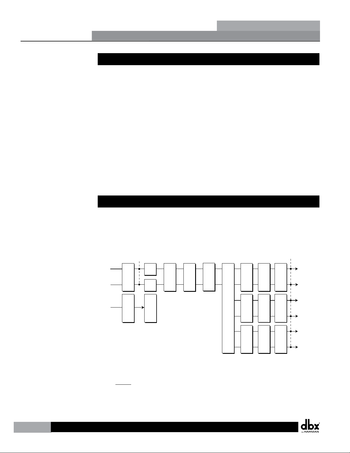
Signal Path Block Diagram
The following diagram shows the logical and intuitive signal path of the input, effects, and
output of the DriveRack PA+.
GEQ
GEQ
Meters
Left Input
Right Input
Left High
Right High
Left Mid
Right Mid
Left Low
Right Low
Mic Input
Outputs
Stereo Compressor
AFS Notch Filters
SubHarmonic Synth
3-Band PEQ 2-Band PEQ 2-Band PEQ
Peak Stop Limiter Peak Stop Limiter Peak Stop Limiter
Alignment Delay Alignment Delay Alignment Delay
Crossover Section - (2X3, 4,5,6)
Stereo/Mono
Pink Noise
Micr Pre amp
RTA
Meters
Connections
When setting up the DriveRack PA+, make connections as follows:
Always• make connections prior to applying power to the unit.
Connect the output from the sending device (mixer) to either of the two XLR Input •
connectors shown below. (Left to left and right to right is recommended)
Section 2
Getting Started
6
DriveRack
®
PA+

Make output connections from the six output XLR connectors on the back panel to the •
input of the selected power amplifiers. (Low out to low amp, mid out to mid amp and
high out to high amp as needed)
If you will be “pinking” (Auto-EQing) the room through the use of the pink noise •
generator, RTA microphone and the Auto-EQ Wizard, connect the RTA microphone to the
front-panel XLR input.
IMPORTANT- It is essential that the power amps are turned off prior to cycling power •
to the DriveRack® PA+. It is standard practice to make sure that your power amps are
the last item turned on and the first turned off.
Once all of the connections have been made and the unit is powered up, you can navigate
through the entire signal path of the DriveRack PA+ from the front panel of the unit. The
display provides you with a clear and concise overview of each aspect of the signal path from
the input to the output section.
Section 2
Getting Started
7
DriveRack
®
PA+
3.1 Basic Navigation Modes
The DriveRack PA+ has been carefully designed and engineered to ensure that all aspects of
operation are intuitive and logical. Simply stated, the DriveRack PA+ operating system was
designed with the user’s best interest in mind.
Navigational aspects of the DriveRack PA+ are clear, concise and more important they are
flexible. The DriveRack PA+ provides you with essentially three different modes of navigation
when performing preset edits.
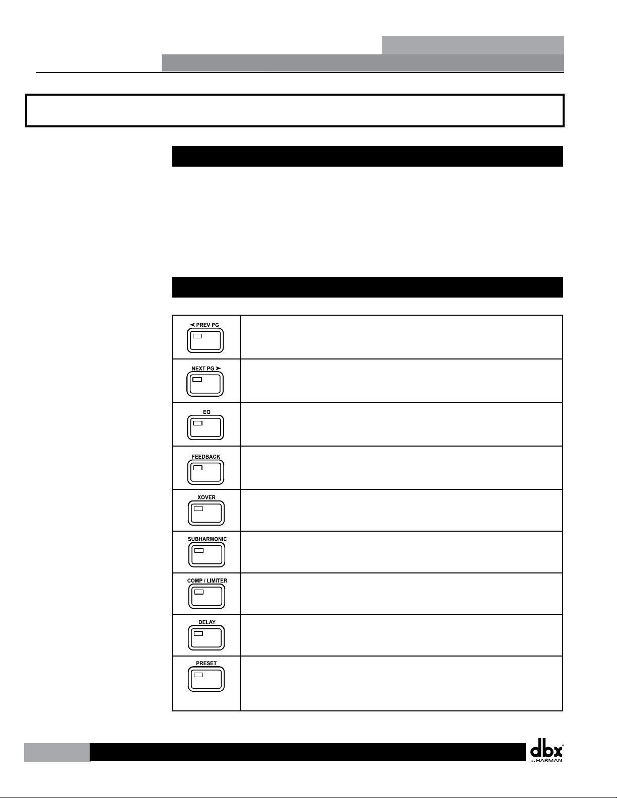
3.2 Button Array Overview
PREVIOUS PAGE - Used to navigate back through the various pages of any
effect or WIZARD.
NEXT PAGE - Used to navigate forward through the various pages of any
effect or WIZARD.
EQ - Used to move to the EQ modules. Successive presses will move you
through the EQ modules in the input section and through EQ modules
located in the output section.
FEEDBACK - Used to move to the Automatic Feedback Suppression module.
XOVER - Used to move to the Crossover module.
SUBHARMONIC - Used to move to the Subharmonic Synthesizer module.
COMP/LIMITER - Used to move to the Input Compressor or Output Limiter
modules. Successive presses will move you through the Input Compressor
and Output Limiter modules.
DELAY - Used to move to the Delay modules.
PRESET/RECALL - Press to view the currently loaded preset. Press and hold
to scroll through presets, where you can press the Data Wheel to load a
new preset or press the PRESET/RECALL button to cancel and return to the
currently loaded preset.
Section 3
Editing Functions
8
DriveRack
®
PA+
Section 3 - Editing Functions
 Loading...