


 Loading...
IMPORTANT SAFETY INSTRUCTIONS
The symbols shown above are internationally accepted symbols that warn of potential hazards with electrical products. The lightning flash with arrowpoint in an equilateral triangle means that there are dangerous voltages present within the unit. The exclamation point in an equilateral triangle indicates that it is necessary for the user to refer to the owner’s manual.
These symbols warn that there are no user serviceable parts inside the unit. Do not open the unit. Do not attempt to service the unit yourself. Refer all servicing to qualified personnel. Opening the chassis for any reason will void the manufacturer’s warranty. Do not get the unit wet. If liquid is spilled on the unit, shut it off immediately and take it to a dealer for service. Disconnect the unit during storms to prevent damage.
SAFETY INSTRUCTIONS
Notice For Customers If Your Unit Is Equipped With A Power Cord.
WARNING: THIS APPLIANCE SHALL BE CONNECTED TO A MAINS SOCKET OUTLET WITH A PROTECTIVE EARTHING CONNECTION.
The cores in the mains lead are coloured in accordance with the following code:
GREEN and YELLOW - Earth |
BLUE - Neutral |
BROWN - Live |
As colours of the cores in the mains lead of this appliance may not correspond with the coloured markings identifying the terminals in your plug, proceed as follows:
•The core which is coloured green and yellow must be connected to the terminal in the plug marked with the letter E, or with the earth symbol, or coloured green, or green and yellow.
•The core which is coloured blue must be connected to the terminal marked N or coloured black.
•The core which is coloured brown must be connected to the terminal marked L or coloured red.
This equipment may require the use of a different line cord, attachment plug, or both, depending on the available power source at installation. If the attachment plug needs to be changed, refer servicing to qualified service personnel who should refer to the table below. The green/ yellow wire shall be connected directly to the units chassis.
|
CONDUTOR |
WIRE COLOR |
||
|
Normal |
Alt |
||
|
|
|
||
L |
|
LIVE |
BROWN |
BLACK |
N |
|
NEUTRAL |
BLUE |
WHITE |
E |
|
EARTH GND |
GREEN/ |
GREEN |
|
YEL |
|||
|
|
|
|
|
WARNING: If the ground is defeated, certain fault conditions in the unit or in the system to which it is connected can result in full line voltage between chassis and earth ground. Severe injury or death can then result if the chassis and earth ground are touched simultaneously.
If you want to dispose this product, do not mix it with general household waste. There is a separate collection system for used electronic products in accordance with legislation that requires proper treatment, recovery and recycling.
Private household in the 25 member states of the EU, in Switzerland and Norway may return their used electronic products free of charge to designated collection facilities or to a retailer (if you purchase a similar new one).
For Countries not mentioned above, please contact your local authorities for a correct method of disposal.
By doing so you will ensure that your disposed product undergoes the necessary treatment, recovery and recycling and thus prevent potential negative effects on the environment and human health.
WARNING FOR YOUR PROTECTION
READ THE FOLLOWING:
KEEP THESE INSTRUCTIONS
HEED ALL WARNINGS
FOLLOW ALL INSTRUCTIONS
the apparatus shall not be exposed to dripping or splashing liquid and no object filled with liquid, such as vases, shall be placed on the apparatus.
CLEAN ONLY WITH A DRY CLOTH.
DO NOT BLOCK ANY OF THE VENTILATION OPENINGS. INSTALL IN ACCORDANCE WITH THE MANUFACTURER’S INSTRUCTIONS.
DO NOT INSTALL NEAR ANY HEAT SOURCES SUCH AS RADIATORS, HEAT REGISTERS, STOVES, OR OTHER APPARATUS (INCLUDING AMPLIFIERS) THAT PRODUCE HEAT.
ONLY USE ATTACHMENTS/ACCESSORIES SPECIFIED BY THE MANUFACTURER.
UNPLUG THIS APPARATUS DURING LIGHTNING STORMS OR WHEN UNUSED FOR LONG PERIODS OF TIME.
Do not defeat the safety purpose of the polarized or grounding-type plug. A polarized plug has two blades with one wider than the other. A grounding type plug has two blades and a third grounding prong. The wide blade or third prong are provided for your safety. If the provided plug does not fit your outlet, consult an electrician for replacement of the obsolete outlet.
Protect the power cord from being walked on or pinched particularly at plugs, convenience receptacles, and the point where they exit from the apparatus.
Use only with the cart stand, tripod bracket, or table specified by the manufacture, or sold with the apparatus. When a cart is used, use caution when moving the cart/apparatus combination to avoid injury from tip-over.
Refer all servicing to to qualified service personnel. Servicing is required when the apparatus has been damaged in any way, such as power-supply cord or plug is damaged, liquid has been spilled or objects have fallen into the apparatus, the apparatus has been exposed to rain or moisture, does not operate normally, or has been dropped.
POWER ON/OFF SWITCH: The Power switch used in this piece of equipment DOES NOT break the connection from the mains.
MAINS DISCONNECT: The plug shall remain readily operable. For rack-mount or installation where plug is not accessible, an all-pole mains switch with a contact separation of at least 3 mm in each pole shall be incorporated into the electrical installation of the rack or building.
If connected to 240V supply, a suitable CSA/UL certified power cord shall be used for this supply.

IMPORTANT SAFETY INSTRUCTIONS
DECLARATION OF CONFORMITY
Manufacturer’s Name: |
dbx Professional Products |
Manufacturer’s Address: |
8760 S. Sandy Parkway |
|
Sandy, Utah 84070, USA |
declares that the product: |
|
Product name: dbx 640, dbx 641 dbx 640m, dbx 641m
Note: Product name may be suffixed by the EU.
Product option: None
conforms to the following Product Specifications:
Safety: |
IEC 60065 -01+Amd 1 |
EMC: |
EN 55022:2006 |
|
EN 55024:1998 |
|
FCC Part 15 |
Supplementary Information: |
|
The product herewith complies with the requirements of the:
Low Voltage Directive 2006/95/EC
EMC Directive 2004/108/EC.
RoHS Directive 2002/95/EC
WEEE Directive 2002/96/EC
With regard to Directive 2005/32/EC and EC Regulation 1275/2008 of 17 December 2008, this product is designed, produced, and classified as Professional Audio Equipment and thus is exempt from this Directive.
Roger Johnsen
Director, Engineering
Signal Processing
8760 S. Sandy Parkway
Sandy, Utah 84070, USA
Date: March 9, 2011
European Contact: Your local dbx Sales and Service Office or
Harman Signal Processing
8760 South Sandy Parkway
Sandy, Utah
84070 USA
Ph: (801) 566-8800
Fax: (801) 568-7583
DECLARATION OF CONFORMITY
Manufacturer’s Name: |
dbx Professional Products |
Manufacturer’s Address: |
8760 S. Sandy Parkway |
|
Sandy, Utah 84070, USA |
declares that the product: |
|
Product name: dbx 1260, dbx 1261 dbx 1260m, dbx 1261m
Note: Product name may be suffixed by the EU.
Product option: None
conforms to the following Product Specifications:
Safety: |
IEC 60065 -01+Amd 1 |
EMC: |
EN 55022:2006 |
|
EN 55024:1998 |
|
FCC Part 15 |
Supplementary Information: |
|
The product herewith complies with the requirements of the:
Low Voltage Directive 2006/95/EC
EMC Directive 2004/108/EC.
RoHS Directive 2002/95/EC
WEEE Directive 2002/96/EC
With regard to Directive 2005/32/EC and EC Regulation 1275/2008 of 17 December 2008, this product is designed, produced, and classified as Professional Audio Equipment and thus is exempt from this Directive.
Roger Johnsen
Director, Engineering
Signal Processing
8760 S. Sandy Parkway
Sandy, Utah 84070, USA
Date: March 9, 2011
European Contact: Your local dbx Sales and Service Office or
Harman Signal Processing
8760 South Sandy Parkway
Sandy, Utah
84070 USA
Ph: (801) 566-8800
Fax: (801) 568-7583
U.K. MAINS PLUG WARNING
A molded mains plug that has been cut off from the cord is unsafe. Discard the mains plug at a suitable disposal facility.
NEVER UNDER ANY CIRCUMSTANCES SHOULD YOU INSERT A DAMAGED OR CUT MAINS PLUG INTO A 13 AMP POWER SOCKET.
Do not use the mains plug without the fuse cover in place. Replacement fuse covers can be obtained from your local retailer. Replacement fuses are 13 amps and MUST be ASTA approved to BS1362.
ELECTROMAGNETIC COMPATIBILITY
This device complies with part 15 of the FCC Rules and the Product Specifications noted on the Declaration of Conformity. Operation is subject to the following two conditions:
•this device may not cause harmful interference, and
•this device must accept any interference received, including interference that may cause undesired operation.
Operation of this unit within significant electromagnetic fields should be avoided.
• use only shielded interconnecting cables.

|
ZonePROTM |
|
Table of Contents |
|
|
TOC
Section 1 - Introduction........................................ |
1 |
8.6 |
Factory Reset Procedures................................. |
44 |
|
1.1 |
ZonePRO Overview.......................................... |
1 |
8.7 |
Technical Specifications.................................. |
46 |
1.2 |
Features........................................................ |
1 |
8.8 |
Wiring Diagrams............................................. |
51 |
1.3 |
Included Items............................................... |
2 |
8.9 |
Copyrights..................................................... |
52 |
1.4 |
ZonePRO Support Resources............................. |
2 |
|
|
|
1.5 |
Service Contact Info....................................... |
2 |
|
|
|
1.6 |
Warranty....................................................... |
3 |
|
|
|
Section 2 - ZonePRO Designer GUI........................... |
4 |
|
2.1 |
ZonePRO Designer Overview............................. |
4 |
2.2 |
GUI System Requirements................................ |
4 |
2.3 |
GUI Installation............................................. |
5 |
2.4 |
Quick Start – Connecting via RS-232................. |
5 |
Section 3 - Getting Started.................................... |
8 |
|
3.1 |
Front Panel – 640/640m, 1260/1260m.............. |
8 |
3.2 |
Front Panel – 641/641m, 1261/1261m.............. |
9 |
3.3 |
Rear Panel..................................................... |
10 |
Section 4 - Zone Controllers................................... |
12 |
|
4.1 |
ZC Descriptions.............................................. |
12 |
4.2 |
ZC Wiring...................................................... |
15 |
4.3 |
ZC-4 Wiring................................................... |
18 |
4.4 |
ZC DIP Switches & Programming....................... |
19 |
Section 5 - Link I/O.............................................. |
22 |
|
5.1 |
Link I/O Overview.......................................... |
22 |
5.2 |
Jumpers........................................................ |
22 |
5.3 |
Link I/O Wiring.............................................. |
24 |
Section 6 - Networking.......................................... |
25 |
|
6.1 |
Default ZonePRO Network Settings.................... |
25 |
6.2 |
Networking Overview...................................... |
25 |
6.3 |
Overview of TCP/IP Basics.............................. |
26 |
6.4 |
Connecting via direct-connect Ethernet............. |
27 |
6.5 |
Setup of a simple isolated Ethernet network...... |
28 |
6.6 |
Adding the ZonePRO to an existing Local Area |
|
Network.............................................................. |
30 |
|
6.7 |
Proxy............................................................ |
31 |
6.8 |
Virtual Private Networks (VPN)......................... |
32 |
6.9 |
Network Considerations and Limitations............. |
32 |
6.10 Network Troubleshooting............................... |
33 |
|
Section 7 - Application Guide................................. |
34 |
|
7.1 |
Restaurant Application.................................... |
34 |
7.2 |
Health Club Application.................................. |
36 |
7.3 |
Nightclub Application..................................... |
38 |
Section 8 - Appendix............................................. |
40 |
|
||
8.1 |
ZonePRO 640/641 Block Diagram...................... |
40 |
|
|
8.2 |
ZonePRO 640m/641m Block Diagram................. |
41 |
|
|
8.3 |
ZonePRO 1260/1261 Block Diagram.................. |
42 |
|
|
8.4 |
ZonePRO 1260m/1261m Block Diagram............. |
43 |
|
|
8.5 |
Firmware Updates........................................... |
44 |
|
|
|
|
|
|
|
|
|
|
|
|

|
ZonePROTM |
|
Introduction |
Section 1 |
|
|
Section 1 - Introduction
1.1 ZonePRO Overview
Congratulations on your purchase of the dbx® ZonePRO. The ZonePRO products are based on the same unparalleled design philosophy that made the DriveRack family famous. This
philosophy, “To provide everything you need between the sources and the amplifiers”, creates a full-featured processor capable of almost any BGM or commercial audio application.
The proceeding chart outlines the major differences between the dbx ZonePRO models.
|
|
|
Balanced |
Unbalanced |
2 Channel |
Front Panel |
Ethernet |
Mix Sources |
Ambient Noise |
|
Total Inputs |
Total Outputs |
Mic/Line |
RCA Line |
|||||
|
S/PDIF Input |
Control |
Port |
to Zones |
Compensation |
||||
|
|
|
Inputs |
Inputs |
|||||
|
|
|
|
|
|
|
|
||
|
|
|
|
|
|
|
|
|
|
1260m |
12 |
6 |
6 |
4 Pair |
Q |
Q |
Q |
Q |
Q |
|
|
|
|
|
|
|
|
|
|
1260 |
12 |
6 |
2 |
8 Pair |
Q |
Q |
Q |
Q |
|
|
|
|
|
|
|
|
|
|
|
1261m |
12 |
6 |
6 |
4 Pair |
Q |
|
Q |
Q |
Q |
|
|
|
|
|
|
|
|
|
|
1261 |
12 |
6 |
2 |
8 Pair |
Q |
|
Q |
Q |
|
|
|
|
|
|
|
|
|
|
|
640m |
6 |
4 |
4 |
2 Pair |
|
Q |
Q |
Q |
Q |
|
|
|
|
|
|
|
|
|
|
640 |
6 |
4 |
2 |
4 Pair |
|
Q |
|
|
|
|
|
|
|
|
|
|
|
|
|
641m |
6 |
4 |
4 |
2 Pair |
|
|
Q |
Q |
Q |
|
|
|
|
|
|
|
|
|
|
641 |
6 |
4 |
2 |
4 Pair |
|
|
|
|
|
|
|
|
|
|
|
|
|
|
|
1.2 Features
• Advanced Feedback Suppression (AFS™) |
• 2 Level Priority Ducker |
||
• |
AutoWarmth® |
• Configuration, Scene, & Schedule Wizards |
|
• Auto Gain Control (AGC) |
• Compatible with dbx ZC Wall Panel Controllers |
||
• Ambient Noise Compensation (640m, 641m, 1260m, & 1261m |
• Independent Routing of Sources to Zones |
||
|
models only) |
• Independent Mixing of Sources to Zones (640 & 641 do not |
|
• |
Bandpass/Crossover Filters |
|
support source mixing) |
• |
Compression |
• Independent Zone Volume & Source Selection Control |
|
• |
Delay |
• RS-232 & Ethernet Control (640 & 641 models do not support |
|
• |
De-Essing |
|
Ethernet control) |
• |
Limiting |
• |
Security Lockout |
• |
Noise Gating |
• |
Switchable Mic/Line Inputs |
• |
Notch Filtering |
• IEC, UI, and CSA Certified |
|
• |
Parametric EQ |
|
|
1

Section 1 |
Introduction |
|
ZonePROTM |
|
|
|
1.3Included Items
•ZonePRO Processor
•Power Cable
•RS-232 Null Modem Cable
•Ethernet Crossover Cable (excluded from 640 & 641 models)
•Software CD-ROM
•Installation Guide
1.4ZonePRO Support Resources
ZonePRO Designer Help - After installing the ZonePRO Designer GUI, see the included help for detailed information regarding ZonePRO programming and configuration.
Training Videos - Training videos can be found under the “Training” section of our website located at www.dbxpro.com.
FAQs/Solutions - Answers to frequently asked questions and solutions to common problems can be found under the “Support” section at www.dbxpro.com.
dbx User Forum - The dbx User Forum can be found at www.dbxpro.com. Here you can search the forum for specific topics or ask other ZonePRO users questions regarding the ZonePRO products.
1.5 Service Contact Info
If you require technical support, contact dbx Technical Support. Be prepared to accurately describe the problem. Know the serial number of your device – this is printed on a sticker attached to the chassis. If you have not already taken the time to register your product, please do so now. You may register online at www.dbxpro.com or fill out and send in the included warranty registration card.
Before you return a product to the factory for service, we recommend you refer to the manual. Make sure you have correctly followed installation steps and operation procedures. For further technical assistance or service, please contact our Technical Support Department at (801)
568-7660 or visit the support pages at www.dbxpro.com. If you need to return a product to the factory for service, you MUST first contact Technical Support or fill out the return authorization request form on the website to obtain a Return Authorization Number.
No returned products will be accepted at the factory without a Return Authorization
Number.
Please refer to the Warranty information on the following page, which extends to the first end-user. After expiration of the warranty, a reasonable charge will be made for parts, labor, and packing if you choose to use the factory service facility. In all cases, you are responsible for transportation charges to the factory. dbx will pay return shipping if the device is still under warranty.
Use the original packing material if it is available. Mark the package with the name of the shipper and with these words in red: DELICATE INSTRUMENT, FRAGILE! Insure the package properly. Ship prepaid, not collect. Do not ship parcel post.
2

|
ZonePROTM |
|
Introduction |
Section 1 |
|
|
1.6 Warranty
This warranty is valid only for the original purchaser and only in the United States.
1.The warranty registration card that accompanies this product must be mailed within 30 days after purchase date to validate this warranty. You can also register online at www. dbxpro.com. Proof-of-purchase is considered to be the responsibility of the consumer. A copy of the original purchase receipt must be provided for any warranty service.
2.dbx warrants this product, when bought and used solely within the U.S., to be free from defects in materials and workmanship under normal use and service.
3.dbx liability under this warranty is limited to repairing or, at our discretion, replacing defective materials that show evidence of defect, provided the product is returned to dbx WITH RETURN AUTHORIZATION from the factory, where all parts and labor will be covered up to a period of two years. A Return Authorization number must first be obtained from dbx. The company shall not be liable for any consequential damage as a result of the product’s use in any circuit or assembly.
4.dbx reserves the right to make changes in design or make additions to or improvements upon this product without incurring any obligation to install the same additions or improvements on products previously manufactured.
5.The foregoing is in lieu of all other warranties, expressed or implied, and dbx neither assumes nor authorizes any person to assume on its behalf any obligation or liability in connection with the sale of this product. In no event shall dbx or its dealers be liable for special or consequential damages or from any delay in the performance of this warranty due to causes beyond their control.
3

Section 2 |
ZonePRO Designer GUI |
|
ZonePROTM |
|
|
|
Section 2 - ZonePRO Designer GUI
2.1 ZonePRO Designer Overview
The ZonePRO Designer Graphic User Interface (GUI) is the included software application which is used for programming the ZonePRO products. The GUI provides network tools for configuring your control network as well as multiple “Wizard” functions for configuring the system routing and in-wall dbx Zone Controllers. The GUI also allows you to adjust DSP effect parameters and even create automatic system changes (referred to as “Scene Changes”).
Understanding the ZonePRO Designer GUI is essential for getting the most out of the ZonePRO processors. After installing the ZonePRO Designer GUI, please see the software application’s help section for detailed information and assistance with the ZonePRO Designer GUI. Training videos are also available at www.dbxpro.com.
2.2 GUI System Requirements
1 GHz or faster processor
Windows 2000/XP/Vista (32 bit)/7 (32 bit) 256 MB RAM (512 MB Recommended)
Recommended screen resolution: 1024 x 768 pixels or higher
4
|
ZonePROTM |
|
ZonePRO Designer GUI |
Section 2 |
|
|
2.3GUI Installation
1.Install the ZonePRO GUI software onto your computer from either the dbx website at www.dbxpro.com or from the included CD ROM.
 We highly recommend disabling virus protection software during the installation of ZonePRO Designer.
2.The application will proceed to prompt you for the installation location.
3.Once the software installation has been completed, it is recommended that you restart your computer.
2.4Quick Start – Connecting via RS-232
In order to program the ZonePRO processors, the ZonePRO Designer GUI must be in communication with the ZonePRO device (this is referred to as “Online”). Once communication is established, the ZonePRO processor can be programmed in real-time, or if a program has already been created, it can be loaded into the device.
If your computer does not have a built in RS-232 port you must use a compatible RS-232 peripheral, such as an RS-232 PCI card, RS-232 PCMCIA card, or USB to Serial adapter. Please visit the FAQs section of the dbx website for the latest information on compatible RS-232 peripherals.
Most ZonePRO models also allow you to communicate via Ethernet, the exception being the 640 and 641 models, which do not have an Ethernet control port. If you are connecting via Ethernet and require assistance, please see “Section 6 - Networking”.
 It is highly recommended that ZonePRO installers do have the means to communicate with the ZonePRO processors via RS-232. If a firmware update is ever required, the firmware update must be applied using the RS-232 connection!
Going Online via RS-232 |
ZonePRO |
Computer |
|
1. Connect your computer to the ZonePRO’s front or rear RS-232 |
|
port using the provided dbx female to female null modem |
PC |
cable. |
|
A straight-through RS-232 cable will not work! If using |
|
a USB to Serial adapter, the dbx null modem cable must be |
dbx RS-232 Cable |
plugged in between the adapter and the ZonePRO. See section “8.8 Wiring Diagrams” for a wiring diagram of the RS-232 null modem cable.
2. Launch ZonePRO Designer.
5
Section 2 |
ZonePRO Designer GUI |
|
ZonePROTM |
|
|
|
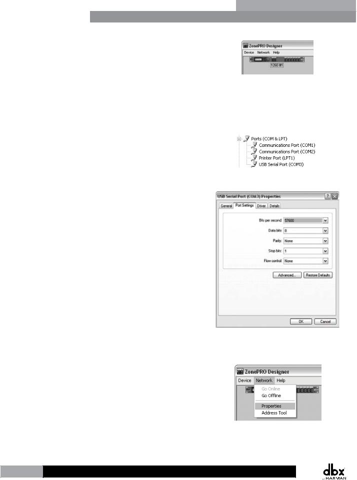
3.Wait approximately 10 seconds after the main ZonePRO Designer window has appeared. If a ZonePRO icon appears in the upper left hand corner of the window, you are online with the processor and ready to begin programming. Simply double left click on the ZonePRO icon to open the Program Screen and begin programming. If the icon does not automatically appear, proceed with these instructions.
4.Go into Window’s Device Manager > Ports. Take note of your COM port’s assigned COM number (shown in parenthesis). If you do not see your COM port here, you may need to reinstall the drivers for your COM port peripheral.
5.Double left click on the connected COM port listed in the previous step. Click the Port Settings tab and set your COM port settings as shown to the right then click the OK button.
6.Go back into ZonePRO Designer and go to Network > Properties.
6
|
ZonePROTM |
|
ZonePRO Designer GUI |
Section 2 |
|
|
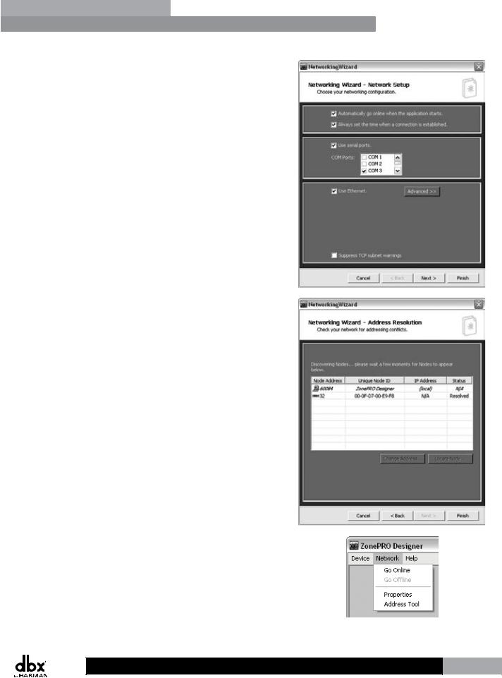
7.Ensure that the “Automatically go online when the application starts” option is checked and the “Use serial ports” option is checked. In the COM Ports combo box, uncheck any unused COM ports and check only the COM port number which you noted in step 4. Click the Next button twice.
8.Your connected ZonePRO device should appear on the second row of the table and have a Status of “Resolved”. If it does not, ensure that the RS-232 cable is securely connected and that you are using the correct RS-232 cable and a compatible RS-232 peripheral. If the ZonePRO device appears in the table proceed by clicking the Finish button.
9.Select Network > Go Online. The icon of the ZonePRO should now appear in the upper left corner of the window. You are now online with the processor and ready to begin
programming. Simply double left click on the ZonePRO icon to open the Program Screen and begin programming.
7

Section 3 |
Getting Started |
|
ZonePROTM |
|
|
|
Section 3 - Getting Started
3.1 Front Panel – 640/640m, 1260/1260m
|
|
640 Front Panel |
|
1 |
2 |
3 |
4 |
|
|||
7 |
7 |
5 |
5 |
6 |
6 |
7 |
7 |
5 |
5 |
6 |
6 |
640m Front Panel
1 |
2 |
3 |
4 |
|
7 |
7 |
5 |
5 |
6 |
6 |
7 |
7 |
5 |
5 |
6 |
6 |
|
|
1260 Front Panel |
|
1 |
2 |
3 |
4 |
|
|||
7 |
7 |
5 |
5 |
6 |
6 |
7 |
7 |
7 |
5 |
5 |
5 |
6 |
6 |
6 |
7 |
|
ZonePRO1260 |
|
5 |
Digital Zone Processor |
|
6 |
||
|
1260m Front Panel
|
|
|
|
7 |
7 |
1 |
2 |
3 |
4 |
|
|
|
5 |
5 |
|||
|
|
|
|
||
|
|
|
|
6 |
6 |
7 |
7 |
5 |
5 |
6 |
6 |
7 |
7 |
5 |
5 |
6 |
6 |
1. Front Panel LCD
Displays information relating to parameters such as source selection, page steering, zone volumes, and mutes.
2. Parameter Select Buttons 1-3
Allows selection of parameters on display.
3. Data Wheel
Used to edit parameter values.
4. Page Buttons
Allows paging microphone path selection for page steering of the ML1 and ML2 inputs.
5. Output Select Button
Allows selection of outputs for controlling source selection, zone volume control, and zone muting.
6. Output Meter
Six-segment output level meter representing -30dBu to +20dBu.
7. Threshold Indicator
Indicates that the threshold level has been exceeded within the output dynamics processor and that dynamics processing may be occurring.
8

|
ZonePROTM |
|
Gettibg Started |
Section 3 |
|
|
and dynamics processing may be occurring.
3.2 Front Panel – 641/641m, 1261/1261m
641 Front Panel
1 |
3 |
641m Front Panel
1 |
2 |
3 |
1261 Front Panel
|
|
|
ZonePRO1261 |
1 |
2 |
3 |
Digital Zone Processor |
|
1261m Front Panel
1 |
2 |
3 |
1. Front PC Port (RS-232)
Connect this serial port to the PC for configuration, control, and monitoring. It can also be used for communication with a third party control system. The baud rate of this port is 57600.
 Front and rear PC ports should not be used at the same time!
2. Network Traffic LED (641m, 1261, and 1261m only)
This LED (when lit), indicates that network traffic is present.
3. Power LED
This LED (when lit) indicates that the ZonePRO device is currently powered on.
9
Section 3 |
Getting Started |
|
ZonePROTM |
|
|
|
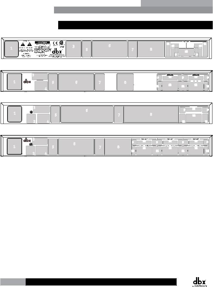
3.3 Rear Panel
640/641 Rear Panel
1 |
3 |
|
6 |
|
5 |
7 |
|
|
|
11 |
10 |
10 |
11 |
8 |
|
12 |
|
|
|
|
|
|
9 |
9 |
|
640m/641m Rear Panel
3 |
9 |
|
1 |
5 |
6 |
7 |
8 |
|
4 |
|
|
11 |
|
|
|
|
MIC/LINE |
|
MIC/LINE |
|
10 |
9 |
10 |
9 |
|
ML 2 |
|
ML 1 |
12 |
11 |
12 |
11 |
|
|
|
1260/1261 Rear Panel |
|
|
|
|
|
3 |
|
|
|
|
10 |
|
|
|
|
|
MIC/LINE |
|
|
1 |
6 |
|
9 |
|
|
9 |
5 |
7 |
8 |
ML 2 |
12 ML 1 |
|
|
2 |
4 |
|
11 |
|
|
11 |
|
|
1260m/1261m Rear Panel |
|
||
|
3 |
6 |
|
9 |
|
|
|
|
|||
1 |
5 |
7 |
8 |
||
|
|||||
2 |
4 |
11 |
|
10 |
9 |
10 |
9 |
10 |
9 |
|
|
|
|||
12 |
|
12 |
|
12 |
|
11 |
11 |
11 |
1. Power Connector
Connect the included AC power cable to this IEC connector.
2. S/PDIF Input (1260, 1261, 1260m, and 1261m models only)
Digital audio input for up to two channels of digital audio.
3. Rear PC Port (RS-232)
Connect this serial port to the PC for configuration, control, and monitoring. It can also be used for communication with a third party control system. The baud rate of this port is 57600.
 Front and rear PC ports should not be used at the same time!
4. Ethernet Port (all models except 640 and 641)
Connect this Ethernet port to the PC for configuration, control, and monitoring. It can also be used for communication with a third party control system.
10

|
ZonePROTM |
|
Gettibg Started |
Section 3 |
|
|
5. ZC Input Ports
Allows connection of up to 12 ZC controllers (six per port) for control of volume, source selection, page steering, and scene changes. The top ZC Input port is for IDs 1-6 and the bottom ZC Input port is for IDs 7-12.
6. Analog Outputs
Balanced audio output connections. Connect these outputs to your amplifier input channels.
7. Link Input/Output Ports
Allows duplication of up to six input channels (ML1, ML2, S1, S2, S3, S4) to another ZonePRO device in applications where additional output zones are required.
 All models – with the exception of the 640m and 641m – allow duplication of up to six channels: ML1, ML2, S1, S2, S3, S4. The 640m and 641m models allow duplication of up to four channels: ML1, ML2, S1, S2.
8. RCA Source Inputs
Mono-summed pairs of unbalanced RCA audio inputs.
 Each pair of unbalanced RCA inputs are internally mono summed. This is beneficial when your application requires mono zones. However, when stereo zones are required and stereo imaging is to be
maintained, each stereo source must occupy two pairs of inputs (omitting one jack per pair).
Stereo RCA
Connection Example
L  L
L
R  R
R
Right Left
9. Mic Gain Control
Allows microphone gain control when the mic/line inputs are set to mic level.
10. Signal/Clip LED
This LED indicates when signal is present (green) or the input is clipping (red).
11. Mic/Line Switch
Allows configuration for microphone or line level sources.
12. Mic/Line Input Connectors
These balanced inputs provide Euroblock connectors for mic or line level sources.
 These Euroblock inputs provide 15 Volts of phantom power when the mic/line switch is set to mic level.
11
Section 4 |
Zone Controllers |
|
ZonePROTM |
|
|
|
Section 4 - Zone Controllers
4.1 ZC Descriptions
VOLUME
4 5 6
3 
 7
7
2 |
8 |
1 

 9 0 10
VOLUME
4 5 6 3 
 7
7
2 8
1 

 9 0 10
MUTE
SELECT
A B
 C
C
D
 A
A
 B
B
 C
C
 D
D
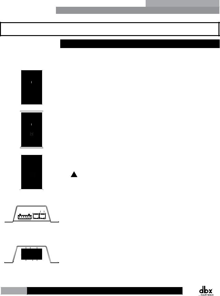
The dbx Zone Controllers (ZCs) provide a user friendly solution for controlling different functions of the ZonePRO processors. The following section provides a description of each of these ZC models.
ZC-1 – The ZC-1 is a programmable zone controller that allows input or output volume level control from a wall panel.
ZC-2 – The ZC-2 is a programmable zone controller that allows output volume level and mute control from a wall panel.
ZC-3 – The ZC-3 is a programmable zone controller that allows control of source selection, page steering, or scene selection via a four position rotary control.
 The ZC-3 must be assigned as ID#1 and connected to the ZonePRO’s top ZC Input connector for scene selection control.
+V |
1 |
2 |
3 |
4 |
OUT |
IN |
1 |
2 |
3 |
|
|
|
|
|
4 |
5 |
6 |
|
|
|
|
|
|
|
ZC-4 – The ZC-4 is a programmable zone controller that allows control of source selection, page steering, or scene selection via contact closure.
 The ZC-4 must be assigned as ID#1 and connected to the ZonePRO’s top ZC Input connector for scene selection control.
ZC-BOB – The ZC-BOB allows parallel (also known as “home run”) cabling of the Zone Controllers.
 Each ZonePRO device can accommodate up to two ZC-BOBs. Daisy chaining ZCs off the ZC-BOB is not supported!
12
Loading...