


286A

Mic Preamp/
Owner/Operator Manual
Manuel d’utilisation
Bedienungsanleitung
Manual de instrucciones
Processor
286A
WARNING
FOR YOUR PROTECTION, PLEASE READ THE FOLLOWING:
WATER AND MOISTURE: Appliance should not be used near water (e.g. near a bath-
tub, washbowl, kitchen sink, laundry tub, in a wet basement, or near a swimming pool,
etc). Care should be taken so that objects do not fall and liquids are not spilled into
the enclosure through openings.
POWER SOURCES: The appliance should be connected to a power supply only of
the type described in the operating instructions or as marked on the appliance.
GROUNDING OR POLARIZATION: Precautions should be taken so that the grounding or polarization means of an appliance is not defeated.
POWER CORD PROTECTION: Power supply cords should be routed so that they are
not likely to be walked on or pinched by items placed upon or against them, paying
particular attention to cords at plugs, convenience receptacles, and the point where
they exit from the appliance.
SERVICING: To reduce the risk of fire or electric shock, the user should not attempt to
service the appliance beyond that described in the operating instructions. All other
servicing should be referred to qualified service personnel.
FOR UNITS EQUIPPED WITH EXTERNALLY ACCESSIBLE FUSE RECEPTACLE:
Replace fuse with same type and rating only.
MULTIPLE-INPUT VOLTAGE: This equipment may require the use of a different line
cord, attachment plug, or both, depending on the available power source at installation. Connect this equipment only to the power source indicated on the equipment rear
panel. To reduce the risk of fire or electric shock, refer servicing to qualified service
personnel or equivalent.
SAFETY INSTRUCTIONS
NOTICE FOR CUSTOMERS IF YOUR UNIT IS EQUIPPED WITH A POWER
CORD.
WARNING: THIS APPLIANCE MUST BE EARTHED.
The cores in the mains lead are coloured in accordance with the following code:
GREEN and YELLOW - Earth BLUE - Neutral BROWN - Live
As colours of the cores in the mains lead of this appliance may not correspond
with the coloured markings identifying the terminals in your plug, proceed as follows:
• The core which is coloured green and yellow must be connected to the
terminal in the plug marked with the letter E, or with the earth symbol, or
coloured green, or green and yellow.
• The core which is coloured blue must be connected to the terminal
marked N or coloured black.
• The core which is coloured brown must be connected to the terminal
marked L or coloured red.
This equipment may require the use of a different line cord, attachment plug, or
both, depending on the available power source at installation. If the attachment
plug needs to be changed, refer servicing to qualified service personnel who
should refer to the table below. The green/yellow wire shall be connected
directly to the unit's chassis.
WARNING: If the ground is defeated, certain fault conditions in the unit or in the
system to which it is connected can result in full line voltage between chassis
and earth ground. Severe injury or death can then result if the chassis and
earth ground are touched simultaneously.
U.K. MAINS PLUG WARNING
A moulded mains plug that has been cut off from the cord is unsafe. Discard the
mains plug at a suitable disposal facility. NEVER UNDER ANY CIRCUM-
STANCES SHOULD YOU INSERT A DAMAGED OR CUT MAINS PLUG INTO
A 13 AMP POWER SOCKET. Do not use the mains plug without the fuse cover
in place. Replacement fuse covers can be obtained from your local retailer.
Replacement fuses are 13 amps and MUST be ASTA approved to BS1362.
The symbols shown above are internationally accepted symbols that warn of
potential hazards with electrical products. The lightning flash with arrowpoint in
an equilateral triangle means that there are dangerous voltages present within
the unit. The exclamation point in an equilateral triangle indicates that it is necessary for the user to refer to the owner’s manual.
These symbols warn that there are no user serviceable parts inside the unit.
Do not open the unit. Do not attempt to service the unit yourself. Refer all servicing to qualified personnel. Opening the chassis for any reason will void the
manufacturer’s warranty. Do not get the unit wet. If liquid is spilled on the unit,
shut it off immediately and take it to a dealer for service. Disconnect the unit
during storms to prevent damage.
CAUTION
ELECTROMAGNETIC COMPATIBILITY
This unit conforms to the Product Specifications noted on the Declaration of
Conformity. Operation is subject to the following two conditions:
• this device may not cause harmful interference, and
• this device must accept any interference received, including interference
that may cause undesired operation.
Operation of this unit within significant electromagnetic fields should be avoided.
• use only shielded interconnecting cables.
DECLARATION OF CONFORMITY
Manufacturer’s Name: dbx Professional Products
Manufacturer’s Address: 8760 S. Sandy Parkway
Sandy, Utah 84070, USA
declares that the product:
dbx 286A
conforms to the following Product Specifications:
Safety: EN 60065 (1993)
IEC65 (1985) with Amendments 1, 2, 3
EMC: EN 55013 (1990)
EN 55020 (1991)
Supplementary Information:
The product herewith complies with the requirements of the Low
Voltage Directive 73/23/EEC and the EMC Directive 89/336/EEC as
amended by Directive 93/68/EEC.
dbx Professional Products
President of dbx
8760 S. Sandy Parkway
Sandy, Utah 84070, USA
October 4, 1996
European Contact: Your Local dbx Sales and Service Office or
International Sales Office
68 Sheila Lane
Valparaiso, Indiana
46383, USA
Tel: (219) 462-0938
Fax: (219) 462-4596
RISK OF ELECTRIC SHOCK
DO NOT OPEN
ATTENTION: RISQUE DE CHOC ELECTRIQUE - NE PAS OUVRIR
WARNING: TO REDUCE THE RISK OF FIRE OR ELECTRIC
SHOCK DO NOT EXPOSE THIS EQUIPMENT TO RAIN OR MOISTURE
CONDUCTOR
L
N
E
LIVE
NEUTRAL
EARTH GND
WIRE COLOR
Normal Alt
BROWN
BLUE
GREEN/YEL
BLACK
WHITE
GREEN

Mic Preamp/
1
MANUAL CONTENTS
ENGLISH . . . . . . . . . . . . . . . . . . . . . . . . . . . . . . . . . . . . . . . . . . . . . . . . . . . . . . . . . . . . . . . . . . . . . . .2
FRAN‚AIS . . . . . . . . . . . . . . . . . . . . . . . . . . . . . . . . . . . . . . . . . . . . . . . . . . . . . . . . . . . . . . . . . . . . . . .15
DEUTSCH . . . . . . . . . . . . . . . . . . . . . . . . . . . . . . . . . . . . . . . . . . . . . . . . . . . . . . . . . . . . . . . . . . . . . . .29
ESPA„OL . . . . . . . . . . . . . . . . . . . . . . . . . . . . . . . . . . . . . . . . . . . . . . . . . . . . . . . . . . . . . . . . . . . . . . .47
ENGLISH CONTENTS
INTRODUCTION . . . . . . . . . . . . . . . . . . . . . . . . . . . . . . . . . . . . . . . . . . . . . . . . . . . . . .2
OPERATING CONTROLS . . . . . . . . . . . . . . . . . . . . . . . . . . . . . . . . . . . . . . . . . . . . . . . . .2
FRONT PANEL . . . . . . . . . . . . . . . . . . . . . . . . . . . . . . . . . . . . . . . . . . . . . . . . . . . .2
INPUT . . . . . . . . . . . . . . . . . . . . . . . . . . . . . . . . . . . . . . . . . . . . . . . . . . . . . . . .2
BYPASS . . . . . . . . . . . . . . . . . . . . . . . . . . . . . . . . . . . . . . . . . . . . . . . . . . . . . . .3
COMPRESSOR . . . . . . . . . . . . . . . . . . . . . . . . . . . . . . . . . . . . . . . . . . . . . . . . . . .3
DE-ESSER . . . . . . . . . . . . . . . . . . . . . . . . . . . . . . . . . . . . . . . . . . . . . . . . . . . . .4
ENHANCER . . . . . . . . . . . . . . . . . . . . . . . . . . . . . . . . . . . . . . . . . . . . . . . . . . . . .4
EXPANDER/GAT E . . . . . . . . . . . . . . . . . . . . . . . . . . . . . . . . . . . . . . . . . . . . . . . . .4
OUTPUT . . . . . . . . . . . . . . . . . . . . . . . . . . . . . . . . . . . . . . . . . . . . . . . . . . . . . .5
REAR PANEL . . . . . . . . . . . . . . . . . . . . . . . . . . . . . . . . . . . . . . . . . . . . . . . . . . . . .5
C
ONNECTING THE 286A TO YOUR SYSTEM . . . . . . . . . . . . . . . . . . . . . . . . . . . . . . . . .6
BASIC CONNECTIONS . . . . . . . . . . . . . . . . . . . . . . . . . . . . . . . . . . . . . . . . . . . . . . .6
B
ASIC OPERATIONS . . . . . . . . . . . . . . . . . . . . . . . . . . . . . . . . . . . . . . . . . . . . . . . . . . .7
U
SING THE PREAMP ALONE . . . . . . . . . . . . . . . . . . . . . . . . . . . . . . . . . . . . . . . . . .7
PROCESSING SECTION . . . . . . . . . . . . . . . . . . . . . . . . . . . . . . . . . . . . . . . . . . . . . . .7
COMPRESSOR . . . . . . . . . . . . . . . . . . . . . . . . . . . . . . . . . . . . . . . . . . . . . . . . . . .7
DE-ESSER . . . . . . . . . . . . . . . . . . . . . . . . . . . . . . . . . . . . . . . . . . . . . . . . . . . . .8
ENHANCER . . . . . . . . . . . . . . . . . . . . . . . . . . . . . . . . . . . . . . . . . . . . . . . . . . . . .8
EXPANDER/GAT E . . . . . . . . . . . . . . . . . . . . . . . . . . . . . . . . . . . . . . . . . . . . . . . . .9
USING THE FOUR PROCESSORS IN DIFFERENT COMBINATIONS . . . . . . . . . . . . . . . . . .9
SUGGESTED SETTINGS/USAGES . . . . . . . . . . . . . . . . . . . . . . . . . . . . . . . . . . . . . . . .10
EXPANDER/GAT E . . . . . . . . . . . . . . . . . . . . . . . . . . . . . . . . . . . . . . . . . . . . . . . . .10
COMPRESSOR . . . . . . . . . . . . . . . . . . . . . . . . . . . . . . . . . . . . . . . . . . . . . . . . . . .11
ENHANCER . . . . . . . . . . . . . . . . . . . . . . . . . . . . . . . . . . . . . . . . . . . . . . . . . . . . .11
PROBLEMS, POSSIBLE CAUSES, SOLUTIONS . . . . . . . . . . . . . . . . . . . . . . . . . . . . . . . . . .11
NOISE/HISS BUILDUP . . . . . . . . . . . . . . . . . . . . . . . . . . . . . . . . . . . . . . . . . . . . . . .11
AUDIBLE DISTORTION, ETC. . . . . . . . . . . . . . . . . . . . . . . . . . . . . . . . . . . . . . . . . . .12
SOUND CUTTING OFF . . . . . . . . . . . . . . . . . . . . . . . . . . . . . . . . . . . . . . . . . . . . . . .12
LISPY VOCALS . . . . . . . . . . . . . . . . . . . . . . . . . . . . . . . . . . . . . . . . . . . . . . . . . . . .12
SHRILLNESS/ EXCESSIVE BRIGHTNESS . . . . . . . . . . . . . . . . . . . . . . . . . . . . . . . . . . .12
LOW RUMBLE/EXCESSIVE LOW FREQUENCIES . . . . . . . . . . . . . . . . . . . . . . . . . . . . .12
NO GAIN REDUCTION METER ACTIVITY WHEN IN COMPRESSION MODE . . . . . . . . . .12
TECHNICAL SUPPORT/FACTORY SERVICE . . . . . . . . . . . . . . . . . . . . . . . . . . . . . . . . . . . .13
R
EGISTRATION CARD/USER FEEDBACK . . . . . . . . . . . . . . . . . . . . . . . . . . . . . . . .13
W
ARRANTY . . . . . . . . . . . . . . . . . . . . . . . . . . . . . . . . . . . . . . . . . . . . . . . . . . . . . . . . .13
B
LOCK DIAGRAM . . . . . . . . . . . . . . . . . . . . . . . . . . . . . . . . . . . . . . . . . . . . . . . . . . . .63
S
PECIFICATIONS . . . . . . . . . . . . . . . . . . . . . . . . . . . . . . . . . . . . . . . . . . . . . . . . . . . . . .64
Processor
286A
2
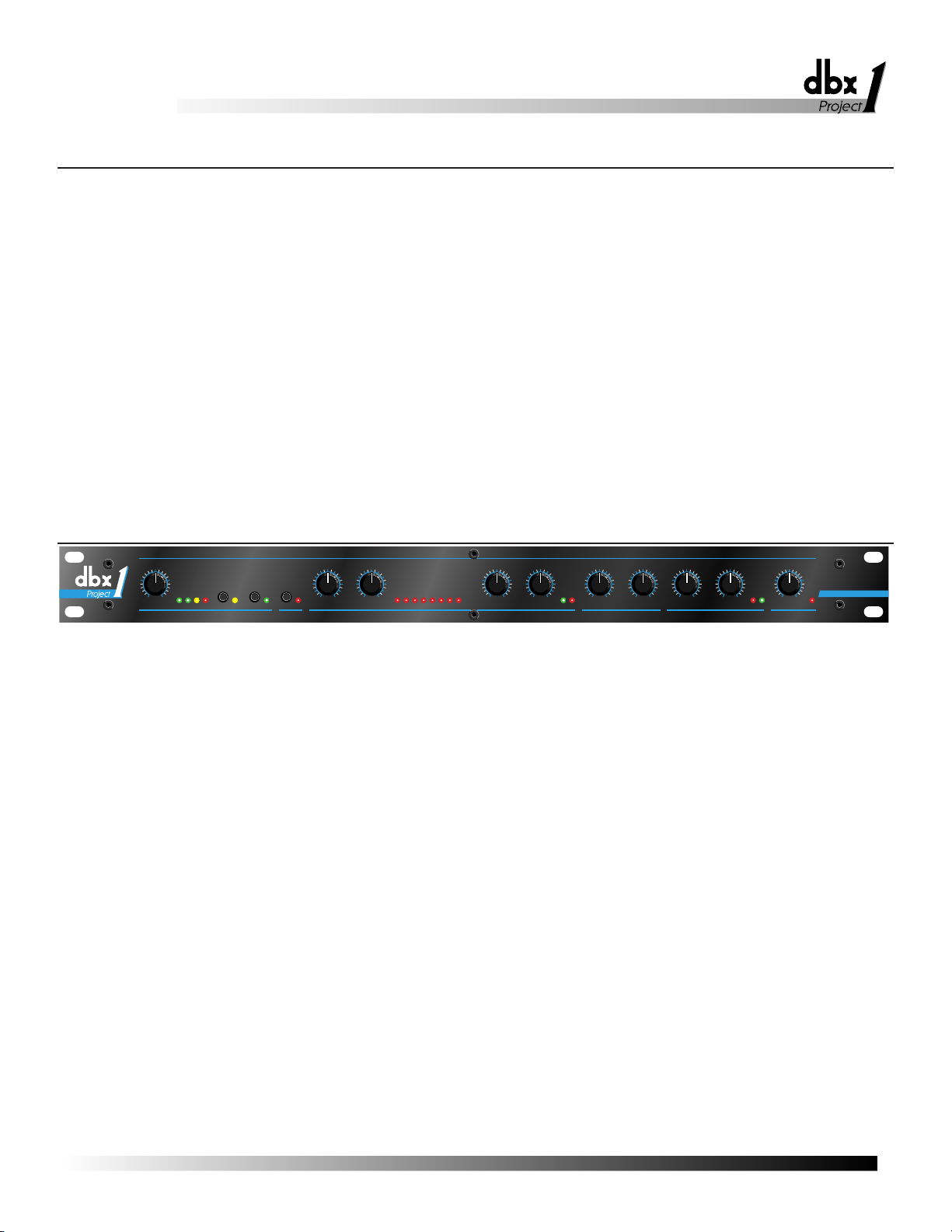
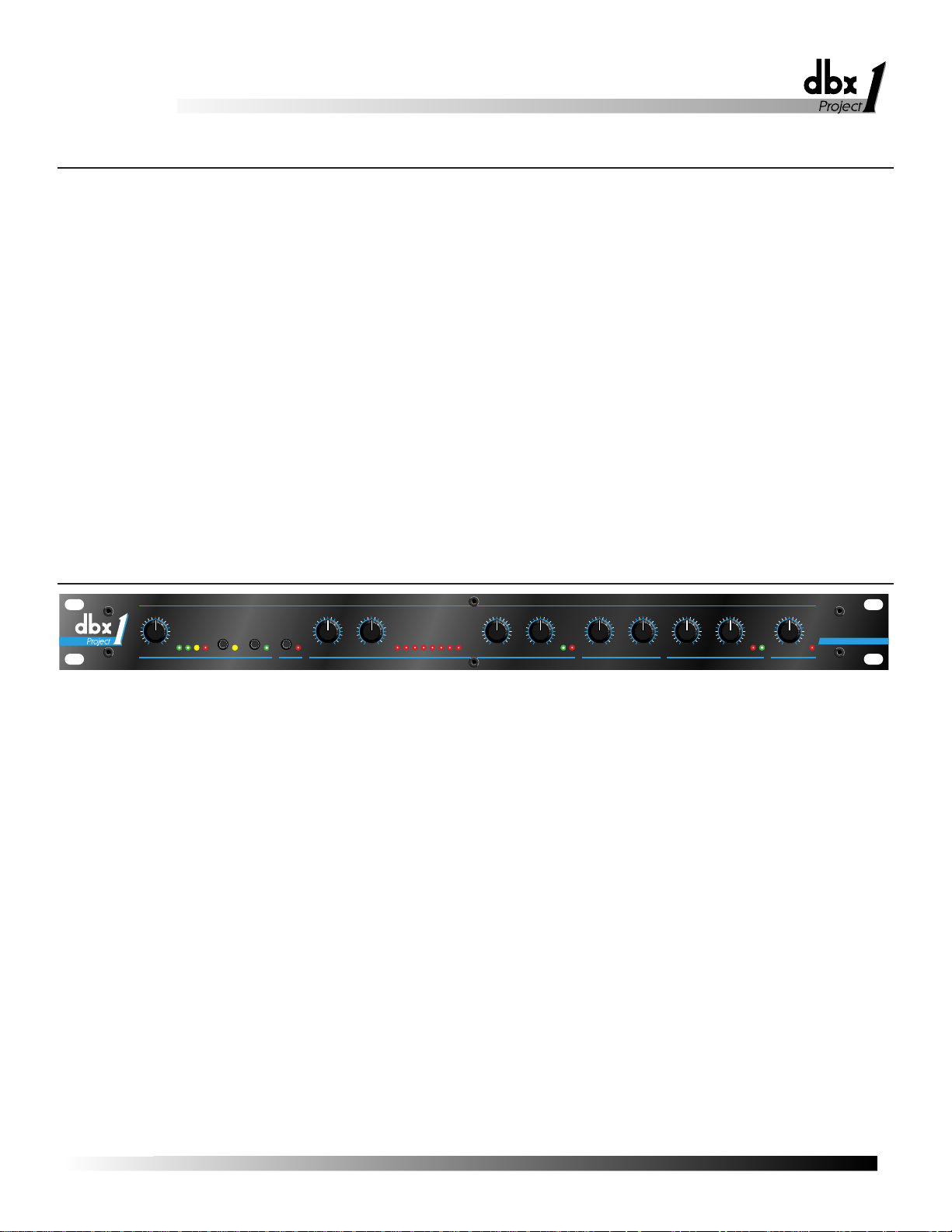
Front Panel
Input
Congratulations on choosing the dbx 286A Mic Preamp/Processor. The 286A is a
powerful, user-friendly unit, providing concise and intuitive controls for all your mic
processing needs, whether you use a microphone to record vocals and acoustic instruments, sample acoustic sounds, or for a public address system installation. The 286A
is also capable of providing effective processing for electronic instruments, individual mixer tracks, and other mono sound sources.
You can think of the 286A as two separate processors, a Mic Preamp Section and a
Processing Section. These two sections can be used together, or the 286A can be
used as a dedicated Mic Preamp by defeating the Processing Section via the front
panel BYPASS switch. Furthermore, the Processing Section provides four specific
types of processing: Compression, De-essing, Enhancement and Expansion/Gating.
These four controls can be used in any combination, as appropriate to your requirements. External audio processors (e.g., equalizer, delay unit, etc.), can be placed in
the signal chain directly between the Mic Preamp Section and remaining 286A processing via the rear panel INSERT jack. We recommend that you take a moment and
read through the 286A manual to better understand the power of the 286AÕs processing, and how you can use the 286A to its fullest potential.
Note: To reduce the risk of damage to your system, set the MIC GAIN control fully counterclockwise and
lower your playback monitor levels before you connect a microphone, power on the unit, or press the
PHANTOM button. This will eliminate spikes and surges, acoustical feedback, loud pops, momentary hiss,
or other unwanted sounds.
MIC GAIN (dB) and LEVEL (dBu) LEDs (including CLIP LED): Use this control to set the level of gain added to the microphone input signal (or a line-level
input). Note that the 286AÕs processing controls, or an external processor connected
to the 286AÕs INSERT, can provide additional gain. Try to set the MIC GAIN control so that you do no have to reset it repeatedly; allow headroom for the maximum
expected levels. For microphones (connected to the XLR MIC INPUT connector),
the 286A can provide +10dB to +60dB of input gain. For line-level inputs (connected to the LINE INPUT jack), the gain is from -20dB to +30dB.
Note: To get the lowest noise possible from the 286A, set the input attenuators (if any) on your recorder or
mixer for nominal levels (often about 3/4” of the way up or at the detent position; refer to the device’s operating manual). Then, set the 286A MIC GAIN so that your recorder or mixer is at its optimal operating
level.
The red CLIP LED (located to the left of the MIC GAIN control) indicates that the
combination of the mic signal and additional gain exceeds the circuitÕs capabilities;
reduce gain via the MIC GAIN control. Set the MIC GAIN control so that the CLIP
LED never lights.
The LEVEL LEDs can also be used to check the strength of the input signal. For
example, the 286A does not support low level microphones plugged into its 1/4Ó
INPUT jack; in this case, the LEVEL LEDs would not light, because the signal is too
low.
INTRODUCTION
OPERATING CONTROLS
48V
PHANTOM
POWER
HIGHPASS
(80Hz)
PROCESS
BYPASS
36 6191215202530
GAIN REDUCTION dB
+
-
0
-10
-30+5+10
OUTPUT
GAIN
dB
2:1
1.5:1 5:1-30 -5
MIN 10:1
EXPANDER/GATE
RATIO
-15
OFF +15
THRESHOLD
dBu
OFF510
9
8
7
6
1
2
3
4
ENHANCER
HF DETAIL
OFF510
9
8
7
6
1
2
3
4
LF DETAIL
OFF510
9
8
7
6
1
2
3
4
DE-ESSER
THRESHOLDFREQUENCY
Hz
dB THRESHOLD
9
OFF510
8
7
6
1
2
3
4
COMPRESSOR
DENSITY
2
OFF510
9
8
7
6
1
3
4
DRIVE
+10
+35
+60
MIC PREAMP
GAIN
dB
LEVEL (dBu)
-10 0 CLIP-20
Mic Preamp/
Processor
286A
CLIP
+20 +40 1k 8k
4k
800 10k
Mic Preamp/
Processor
286A

Mic Preamp/
Bypass
Compressor
PHANTOM POWER Button and LED: When you use phantom powered mics
with your 286A, press the PHANTOM POWER button In to activate the 286AÕs
phantom power, providing +48VDC to the microphone through its connecting cable.
This industry-standard configuration supports virtually all currently-manufactured
phantom power mics. If you do encounter problems, it will typically be with an older
mic. Note that some mics may take several seconds to fully power up when phantom
power is applied. If you are using mics that do not require phantom power, press the
button so that it is in the Out position.
Note: Always plug in a condenser mic with PHANTOM POWER Off and gain levels down. Then switch the
PHANTOM POWER On and adjust the gain as needed.
The yellow PHANTOM POWER LED lights when the PHANTOM POWER button
is in.
HIGHPASS (80Hz) Button and LED: Press this button In to activate the 286AÕs
pre-processing third order filter. The HIGHPASS function filters out frequencies
below 80Hz by 18dB/octave before any compression, de-essing, etc., is applied to
input signal. This is most effective for reducing hum, rumble, wind and other low
frequency problems. The HIGHPASS filter is also before any external processing
provided via the rear panel INSERT jack.
The HIGHPASS LED lights when the HIGHPASS button is In.
PROCESS BYPASS Button and LED: Press this button In to bypass the 286A
Compressor, De-Esser, Enhancer, and Expander/Gate processing circuitry and the
OUTPUT GAIN control (as well as any processing provided by external processors
via the rear panel INSERT jack). In Bypass mode, the 286A will apply gain and filtering as set with Mic Preamp Section controls. BYPASS is equivalent to setting the
286AÕs Compressor DRIVE, De-Esser THRESHOLD, Enchancer LF and HF
DETAIL and Expander/Gate THRESHOLD controls to OFF, the OUTPUT GAIN
control to 0dB (12:00 position), and not connecting any external processing to the
rear panel INSERT jack. Bypass is especially useful for making comparisons
between processed and unprocessed signals.
The red PROCESS BYPASS LED lights when the PROCESS BYPASS button is
pressed In.
Note: The Compressor is Off when the DRIVE is set to OFF.
DRIVE Control: The DRIVE control determines the overall amount of gain reduction
by setting the signal level going into the gain control circuitry. Turning DRIVE
clockwise will increase the input signal, and therefore increase the amount of applied
gain reduction. Turning DRIVE fully counterclockwise (to OFF) allows the compressor to pass all signals unattenuated, effectively bypassing the compressor.
Higher DRIVE settings can cause the Compressor Section to add substantial gain to
signal, especially with low input levels. For example, setting the DRIVE control to
12:00 can add up to 20dB of gain to low signal levels. With hotter input levels going
into the Compressor Section (whether from the MIC INPUT, LINE INPUT or
INSERT jacks), gain addition due to the DRIVE control will be less noticeable.
DENSITY Control: Use this control so speed up or slow down the program-dependent release times. The scale is arbitrary because the release time is automatically
varied according to the nature of the program material (to minimize audible compression-induced side effects). The release rate is from 0 (a slow release for smooth com-
3
Mic Preamp/
Processor
Processor
286A
286A

4
De-Esser
Enhancer
Expander/Gate
pression) to 10 (a fast release where compression follows the envelope of the program very tightly).
There is no absolute ÒrightÓ way to set the DENSITY control. However, in general,
slower settings are useful for gating out noise present behind vocals and acoustic
instruments, while faster settings are useful for tightening up the sound of percussion
instruments (e.g., a kick or snare drum).
GAIN REDUCTION (dB) Meter: This meter shows the true peak gain reduction in
dB. If the red LED at the far left of the meter lights, no further gain reduction is
available.
FREQUENCY Control: Use the control to set the HIGHPASS frequency of the variable filter used in the De-Esser circuitry. Settings between 4-8kHz will yield the best
results for vocal processing, while more extreme settings allow the 286A to be used
in other non-vocal applications.
THRESHOLD Control: Use this control to set the sensitivity of the De-Esser as a
percentage of the average program level at the 286AÕs input. This means that the DeEsser tracks the input level so the amount of de-essing remains constant with changes
in input level.
The De-Esser 1dB and 6dB THRESHOLD LEDs light when the De-Esser is active.
These indicate (in dB) how much sibilance reduction is occurring due to the DeEsser.
Note: The low and high frequency enhancers are off when their respective DETAIL controls are set to OFF.
LF DETAIL Control: The 286AÕs Low Frequency enhancement simultaneously
applies an 80Hz boost and 250Hz cut to the program. This lets you apply substantial
bass boost without making the program sound muddy or boomy due to excessive
mid-bass boost.
HF DETAIL Control: This control determines the amount of High Frequency spectral-enhanced signal added to the input signal. Spectral Enhancement is a form of
dynamic phase and amplitude equalization. Continuous analysis of the input signal
intelligently and automatically determines the amount of equalization necessary at
each moment to achieve detailed, defined audio that is never shrill or over-sibilant.
Note: The Expander/Gate is off when the Expander/Gate THRESHOLD is set to OFF.
THRESHOLD (dB) Control and LEDs: Adjusting this control sets the level at
which the expander/gate will fully open and allow the signal at the input to pass
through to the output. Turing the knob fully counterclockwise (to OFF) allows the
gate to pass all signals unattenuated, effectively bypassing the gate. Turning the knob
fully clockwise causes the gate to attenaute input signals below approximately
+15dBu. The amount of attenaution depends on the setting of the Expander/GateÕs
EXPANSION RATIO.
The THRESHOLD (-) LED (located to the right of the EXPANSION RATIO control)
lights when the signal is below the set THRESHOLD. The THRESHOLD (+) LED
lights when the signal is above the set THRESHOLD. The combination of these two
LEDs also serves as the ÒPOWER ONÓ function, as one or the other is always on.
EXPANSION RATIO Control: This control sets the amount of attenuation applied
to the input signal once it is below the threshold, from gentle downward expansion
(appropriate for mixed program, vocals, etc.), to a hard gating effect (effective for
Mic Preamp/
Processor
286A
Mic Preamp/
Output
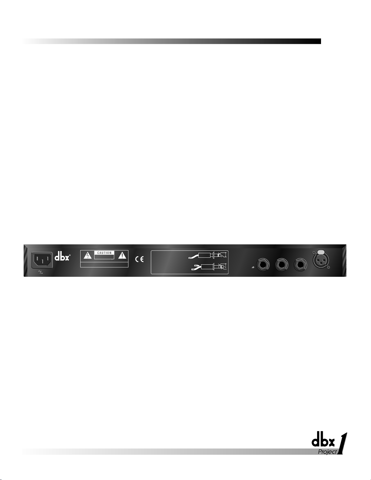
Rear Panel
percussion). Fairly low EXPANSION RATIO settings (and higher Expander/Gate
THRESHOLDs) work best for downward expansion, whereas higher EXPANSION
RATIO settings (clockwise towards 10:1) work best for gating. If a setting produces
undesirable ÒpumpingÓ readjust the Expander/Gate EXPANSION RATIO and
THRESHOLD settings.
Note: The attack and release rate of the Expander/Gate are program-dependent -- very fast for transient
material (e.g., percussion) and slower for material with slow attack (e.g., vocals).
Readjust as needed to gate out noise -- external, as well as hiss from the unit. The
286AÕs other processing can add substantial gain to a signal, especially at higher settings, thereby increasing the noise floor.
GAIN (dB) Control and CLIP LED: The OUTPUT GAIN control sets the level at
the line output. The OUTPUT GAIN control is especially useful to compensate for
the RMS level changes which result from the 286AÕs processing effects. For example, to decrease the overall gain (e.g., when the 286AÕs processing has added too
much gain), simply turn the OUTPUT GAIN control counterclockwise. The OUTPUT GAIN can also be used to counter any gain reduction after you have adjusted
the 286AÕs controls for the desired amount of processing; adjust the OUTPUT GAIN
control clockwise, to add gain as needed.
The red OUTPUT GAIN LED (located to the right of the OUTPUT GAIN control)
lights when the 286A Processing Section is clipping; reduce gain via the OUTPUT
GAIN control. Set this control so that the OUTPUT CLIP LED never lights. If the
OUTPUT CLIP LED is still lit, reduce the gain caused by the 286AÕs processors (e.g.,
high Compressor DRIVE settings) or the gain provided by an external processor connected to the INSERT (if any).
If the meters on your load device (e.g., tape recorder, mixer, etc.) are in the red and
your OUTPUT CLIP LED is not lit, simply reduce the 286AÕs OUTPUT GAIN until
the desired levels are obtained. If your load device is still in the red, reduce its input
attenuators (if available).
MIC INPUT Jack: The 286AÕs MIC INPUT jack supports professional and home
studio microphones by accepting either balanced or unbalanced signal through an
XLR connector. Pins 2 and 3 are symmetrically balanced and floating; thus, either
can be used as ÒHOTÓ without difficulty. Pin 2 is in phase with the TIP of all 1/4Ó
connectors. Pin 1 is connected to the 286AÕs chassis ground.
Note: Use a low impedance mic or a high-to-low impedance matching transformer with a high impedance
mic.
LINE INPUT Jack: Use a 1/4Ó TRS phone plug to connect line level sources to the
286A (e.g., mixer outputs, effects loops, electronic keyboards, etc.). The 286AÕs
LINE INPUT jack accepts either balanced or unbalanced signals. Input impedance is
30k½ unbalanced, 60k½ balanced.
Note: In general, this jack does not support microphones with 1/4” plugs. Use an appropriate 1/4”-to-XLR
adapter and plug the microphone into the MIC INPUT jack.
5
Processor
286A
15 WATTS
PROFESSIONAL PRODUCTS
A HARMAN INTERNATIONAL
COMPANY
SALT LAKE CITY, UTAH
100V 50/60Hz
120V 60Hz
MADE IN USA
MODEL 286A
MIC PREAMP/PROCESSOR
RISK OF ELECTRIC SHOCK
DO NOT OPEN
ATTENTION:RISQUE DE CHOC ELECTRIQUE-NE PAS OUVRIR
WARNING:
TO REDUCE THE RISK OF FIRE OR ELECTRIC
SHOCK DO NOT EXPOSE THIS EQUIPMENT TO RAIN OR MOISTURE
MANUFACTURED UNDER ONE OR MORE OF THE FOLLOWING
U.S. PATENTS: 4,234,804 4,316,107 4,329,598 4,331,931 4,403,199
4,409,500 4,425,551 4,434,380 4,454,433 4,471,324 4,473,793 5,444,788
INSERT
MONO
TIP = OUT (286 PREAMP OUT)
TIP = SEND (286 PREAMP OUT TO EFFECTS)
RING = RETURN (FROM EFFECTS TO 286)
PLUG
286 PREAMP OUT (MULT)
STEREO
PLUG
FOR USE AS AN EFFECTS LOOP
TIP = PIN 2 = +
RING = PIN 3 =
SLEEVE = PIN 1=
-
LINE INPUTOUTPUT INSERT
MIC INPUT

6
LINE OUTPUT Jack: The 286AÕs LINE OUTPUT jack accepts either balanced or
unbalanced 1/4Ó phone plugs. Nominal output signal levels is 0dBu into 600½, and
maximum output signal level is >+21dBu into 600½. Output impedance is 100½
unbalanced, 200½ balanced. The output is tip HOT.
INSERT Jack: The 286A INSERT jack allows you to either add an effects loop
directly into the 286A circuitry chain or take a separate mic preamp signal out.
To connect one or more external processors or effects devices (e.g., an equalizer,
delay unit, etc.) between the Mic Preamp Section and the Processing Section, insert a
1/4Ó TRS plug carrying the external deviceÕs output signal fully into the 286AÕs
INSERT jack; the TIP acts as a Send, carrying the signal from the Mic Preamp
Section at an impedance of 100½, while the RING acts as a Return for external
devices to feed the 286AÕs processing circuitry (i.e., 286AÕs compressor, de-esser,
etc.). This operation requires a Y-cable. When using INSERT as a direct in to the
Processing Section, MIC GAIN control, HIGHPASS button and PHANTOM
POWER will not be active.
To use the INSERT jack to MULT the preamp out (i.e., to provide an output with a
buffered version of the signal after the Mic Preamp circuitry, but before the
Processing Section), insert a Mono 1/4Ó plug fully into the INSERT jack, then pull
the plug out one click. Plug the other end of the cable to the appropriate load. This
will still allow the original signal path to continue to the Processing Section without
interruption.
Note: If the plug is accidentally pushed fully into the INSERT jack, it will break off the connection between
the Mic Preamp and Processing Sections; in this case, there would be no signal at the 286A’s LINE OUTPUT jack.
AC Power: Connect the AC power cord to the AC receptacle on the back of the unit.
Route the AC power cord to a convenient power outlet away from audio lines. The
unit may be turned on and off from a master equipment power switch.
The 286A can be used with any low-level microphone signal (via the MIC INPUT) or
any line-level device (via the LINE INPUT). Some common line-level devices
include: mixing consoles, electronic musical instruments, patch bays, and signal
processors. For all connections, refer to the following steps:
1. Turn Off all equipment before making any connections.
2. Mount the 286A in a rack. (Optional)
Caution: Never remove the cover. There are no user-serviceable parts inside.
The 286A requires one rack space (height) and one rack space (width). It can be
mounted above or below anything that doesnÕt generate excessive heat, since it
requires no special ventilation. Ambient temperature should not exceed 113¡F
(45¡C) when equipment is powered.
3. Make connections via rear panel jacks and connectors according to your
requirements.
A. Connect a microphone to the MIC INPUT XLR connector or a line
level source to the 1/4Ó LINE INPUT jack.
Important: DO NOT connect anything other than a microphone to the MIC INPUT.
B. Connect the load (e.g., mixer, tape recorder, etc.) to the 286AÕs LINE
CONNECTING THE 286A TO YOUR SYSTEM
Basic Connection
Mic Preamp/
Processor
286A

Mic Preamp/
Using the Mic Preamp Alone
(i.e., Using the 286A as a
Dedicated Mic Preamp)
Processing Section
Compressor
OUTPUT jack.
C. Connect an external processor or effects device to the 1/4Ó INSERT
jack. (Optional)
4. Connect the AC power cord to the AC power receptacle on the back of the unit.
Note: We recommend you always power on the unit with the MIC GAIN control set to its minimum level
(fully counterclockwise). This will help in safeguarding your system against sudden spikes and surges,
as well as possible acoustical feedback if a microphone is connected and left “open.”
Note: Check the line voltage (printed on 286A) and verify that it is correct.
The 286AÕs Mic Preamplification Section includes support for phantom-powered
mics, a highpass filter, and an input gain control. Note that these controls are applied
to the input signal before the signal is processed by the 286AÕs Processing Section.
Phantom power is available at the push of a button, providing +48VDC to phantompowered microphones. The 286AÕs phantom power is sufficient for most microphones, However, some vintage condenser mics may require a separate power
source.
Press the HIGHPASS button In to cut signals below 80Hz by 18dB/octave, effectively filtering out mic proximity effects, hum, rumble, wind and other low frequency
Òundesirables.Ó
Use the MIC GAIN control to achieve the best definition and character possible from
your microphone. The 286AÕs Mic Preamp delivers up to 60dB of sonically transparent gain to reveal the detail and audio signature of even the most esoteric mics. It
transforms their low level output signal to a high level, high current signal that is
internally fed to the 286AÕs main processing chain (i.e., compressor, de-esser, etc.)
To use the 286A as a dedicated mic preamp, simply press the BYPASS button to
defeat the Processing Section circuitry. This allows you to use the Mic preampÕs
PHANTOM POWER switch, HIGHPASS button and MIC GAIN control without
routing the signal through any of the processing circuitry.
The 286AÕs Processing Section consists of four specific processors: Compressor , Deesser, Enhancer, Expander/Gate. These four processors can be used in any combination or the 286A can be set as a dedicated single-function processor (refer to the following pages).
A compressor is a device that changes its gain in response to the signal at its input.
Many compressors have a user-selectable level, called THRESHOLD, to help determine when compression occurs. If the input signal is low in level (below the threshold of compression) the compressor gain remains fixed. If the input increases above
the threshold of compression, the gain begins to decrease (i.e., the amount of gain
reduction increases). For very large input signals, the gain can decrease considerably.
On the 286A, compression occurs as an input level is ÒdrivenÓ into gain reduction by
the DRIVE control; as the DRIVE setting (adjusted clockwise from OFF) increases
input gain, the amount of gain reduction also increases. The 286A does not have a
Threshold control; the threshold is established by the setting of the DRIVE control.
Use the Drive control to set the amount of gain reduction (i.e., how much the input
signal is being compressed). Use the DENSITY control to set the compressorÕs
7
BASIC OPERATION
Understanding the 286AÕs Mic Preamp
Processor
286A

8
De-Esser
Enhancer
release time (i.e., how fast the compression circuit returns the input to its original
level).
The 286AÕs patented and versatile Compressor can smoothly and unobtrusively ride
gain, and assertively increase punch and density. The 286A achieves its outstandingly transparent audio performance by finely-tuned control circuitry that eliminates the
dynamic distortions present in most conventional compressors and limiters. The use
of a quiet, low-distortion dbx VCA ensures negligible static distortion and noise.
Compression is especially useful for smoothing out a vocal performance, raising a
signal out of a mix, fattening kick or snare drums, or adding sustain to instruments
(such as an acoustic guitar or bass).
A De-Esser is a device that reduces the high frequency energy present in certain
vocalizations, of which the most common is sibilance. Sibilance is the hissing or
rushing sound produced by blowing air through a constricted (narrow) mouth opening
or across the edge of the teeth, as in the ÒsÓ and ÒshÓ in Òsash.Ó Sibilants contain predominantly high frequency components with a sharp rise above 1kHz and most of the
energy in the 4kHz to 10kHz band, centered on 6kHz to 8kHz.
Adjust the De-EsserÕs FREQUENCY control to set the frequency above which the
286A responds to audio containing sibilants. The 286A detects sibilant material by
comparing the high-frequency energy of an audio signal to the full bandwidth energy
of that signal. When the high-frequency energy is excessive relative to the full bandwidth energy, the 286A quickly reduces the gain, or Òde-esses.Ó The frequency control sets the high-pass filter frequency of the high-frequency level detector. For normal vocal de-essing, the frequency should be set between 4-8kHz. Further adjustment
of the frequency control enables the 286A to be used for processing instrumental
material, such as removing ÒclicksÓ from a close micÕd piano or acoustic guitar.
Adjust the De-EsserÕs THRESHOLD control to quickly reduce any sibilance (i.e.,
excessive vocal sounds like ÒsssÓ), high-frequency overload distortion (e.g., a cymbal
crash that can overload tape, drive amps into distortion and fatigue listeners), or even
guitar string slide noise.
We recommend the 286AÕs De-Esser for use almost exclusively on single voices or
instruments for sibilance. The De-Esser should not be used on mixed program material.
An Enhancer (sometimes called a Spectral Enhancer) adds clarity and detail to vocals
or other line level signals by ÒintelligentlyÕ boosting specific frequency ranges.
Use the HF DETAIL control to add high frequency energy to the input signal. Use
the LF DETAIL to add punch and definition at the lower end of the spectrum.
The HF Detail circuitry in the 286A uses a dynamic shelving equalizer to provide
results superior to even complex equalization. In many situations, the amount of high
frequency content in the material you are working with will vary. Typical equalization schemes will produce results which are right some of the time, and completely
wrong at other times. But not with the 286A. The equalizerÕs dynamic operation and
sliding corner frequency ensure that high frequency enhancement is applied only
when needed and in the specific frequency range necessary to maintain proper spectral balance moment to moment. HF detail is perfect for adding definition to muddy
vocals, guitar or horn tracks. It can also add ÒzingÓ and crispness to percussion
tracks - acoustic or sampled.
Mic Preamp/
Processor
286A

Mic Preamp/
Expander/Gate
Using the Four Processors in
Different Combinations
As you increase the amount of LF Detail, the circuitry boosts lower bass frequencies
while simultaneously cutting problem frequencies in the upper bass/low midrange
region which often makes program material muddy. Use LF Detail to create a Òbig,Ó
chesty, male voice or to add fullness and power to lower frequency percussives (e.g.,
kick, toms, timpani).
A Gate is essentially a device that controls the level of an input signal by ÒopeningÓ
and Òclosing.Ó A user-selected level, called THRESHOLD, helps determine when the
gate opens and closes. If the input signal is above the threshold, the gate is Òopen,Ó
allowing the signal to pass. If the input signal is below the threshold, the gate ÒclosesÓ and the input signal is attenuated. With sufficient attenuation, it effectively cuts
that signal off. On the 286A, the amount of attenuation is set with the EXPANSION
RATIO control.
The 286AÕs gate provides more flexibility than traditional switch gates because it
actually functions as a combination gate/expander. Where switch gates are generally
only suitable for a limited number of uses (e.g., gating percussion), the gate on the
286A acts as a gentle downward expander at low EXPANSION RATIO settings (suitable for vocals, guitar, etc.) and can effectively work as a switch gate when used at
high EXPANSION RATIO settings.
When an input signal exceeds the user-selected THRESHOLD, signals pass unaffected. However, when part of a signal is below THRESHOLD, that part is downward
expanded. (This differs from gating in that the attenuation effect of downward
expansion is gentle.) Downward expansion works well with program material that
has a less defined attack and release. Use downward expansion with voice - as
opposed to percussive sounds which have a quick, defined attach and release.
Adjust the Expander/Gate THRESHOLD and EXPANSION RATIO controls to prevent headphone leakage or to cut the background noise when gain is added at all the
preceding stages of the 286A.
Note: Too high of a THRESHOLD setting with expansion (i.e., lower EXPANSION RATIOs), may cause the
286A to attenuate the desired portion of the signal, as well as the undesired portion. Too high of an
EXPANSION RATIO setting my cause undesirable effects with highly modulated program material like
vocals.
Note: The following example is provided as a guide to highlight how the 286A’s front panel controls can be
used simultaneously for multiple purposes. Suggested settings are specific to this example. Once you
have connected the 286A to your system (see page 7), adjust the 286A’s controls as required to support
your setup and to achieve your desired results (refer to Suggested Settings/Usages, below).
An Example: You are using a condenser microphone to record a vocalist whose ÒsssÓ
sounds sting while the overall character of the vocal part is rather dull and the vocalist is constantly changing his/her distance from the microphone, and your studio is
complete with hum from bad cabling, and noise from heavy construction work nearby. The 286A can be used to rectify each of these problems and also provide additional processing to highlight the best qualities of the vocal performance.
Press the PHANTOM POWER button in to support the phantom power mic (after
reducing playback gain).
Press the HIGHPASS button in to reduce the hum.
Adjust the Compressor DRIVE and DENSITY controls to smooth out the vocal per-
formance. To slow the compressorÕs release time, set the DENSITY control to 0.
Set the De-Esser frequency control to 4kHz (12:00 position).
Adjust the De-Esser THRESHOLD control to reduce the vocalistÕs sibilance.
9
Processor
286A
10
Suggested Settings/Usages
Use the HF DETAIL, to taste, to add life to the vocal. Defeat the LF DETAIL by setting it to OFF.
Set the Expander/Gate THRESHOLD and EXPANSION RATIO controls starting
with a setting of around 11:00. Adjust these controls so that background noises are
gated out when the vocal part is low or not present.
Because minimal processing levels often produce the best results, the 286AÕs processing should initially be applied conservatively (to taste); avoid overusing an effect,
unless it is absolutely necessary. (For example, use De-Essing for sibilance or high
frequency distortion only; otherwise, turn the control OFF. Or, for material already
rich in high frequencies, set the HF DETAIL to Off, or use it minimally.)
This will ensure that the 286AÕs circuitry produces superior audio without any artifacts.
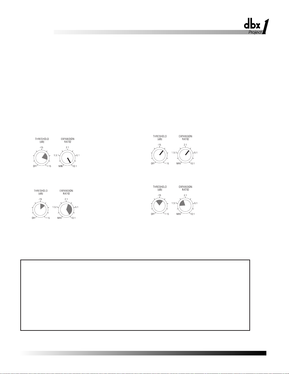
¥Expander/Gate
Note: The Expander/Gate is OFF when the Expander/Gate THRESHOLD is set to the “off” position.
Suggested Initial Gate settings:
Gating Dry Percussive Sounds
(i.e.: Snare Drum, Kick Drum)
Gating Sounds that have Longer Decay
(i.e.: Cymbal, Piano)
Gating Hum or Buzz from Live
Instruments or Recorded Tracks
Downward Expansion to Reduce
Noise Under Smooth Sounds
(i.e.: Vocals, Woodwinds)
¥Enhancer
Note: The High and Low Frequency Enhancers are OFF when their respective DETAIL controls are set to the “off” position.
Suggested Usage:
Female Male Strings/ Club
Voice Voice Keyboard Guitar Bass Guitar Drums Horns Sound/
DJ
LF
Detail -- ➢➢➢ ➤ ➢➢➤
HF
Detail ➤➤➢➤➢➢➤➤
➤ Recommended; These sound sources can be effectively re-energized and enhanced with treatment. Use to taste.
➢ Program-Dependent; Use when program material needs treatment. Make sure you use only as much treatment as needed.
-- Not Recommended. The 286A is generally not applicable to these applications.
Mic Preamp/
Processor
286A

Mic Preamp/
Noise Rushups, Hiss Buildup
Always verify that the problem is not in the source material being fed into the 286A,
or in the other parts of the system. If you still have problems when using the 286A,
consider the following remedies.
Higher DRIVE settings on the compressor often add gain to the signal. If the signal
already has substantial hiss, the compression can actually increase the hiss. As a
compressor releases and the gain of the input signal increases, background noise and
hiss can increase. This is called noise rushup. Remedy this by using compression
conservatively. Also, to reduce noise rushups, especially during pauses, lower the
Compressor DENSITY setting. For both cases, set the Expander/Gate to match the
compressorÕs release time, thereby gating out the noise or hiss as much as possible
without truncating the signal.
Increased hiss can also result from high frequency Òdetailing.Ó The HF DETAIL
enhancer estimates how much high frequency boost is appropriate for a given input
signal. If the signal is dull but noisy (e.g., vocals recorded to a bad cassette), the HF
DETAIL will make it brighter and can pull up hiss to objectionable levels. (The hiss
will often be audibly modulated by the material because the HF DETAIL is adaptive
to the material.) Reduce the setting of the HF DETAIL control until the effect is no
longer objectionable.
dbx Professional Products manufactures several processors that are more suitable for
this type of low-quality material because they have built-in dynamic single-ended
noise reduction circuits. The dbx Project 1 296 Spectral Enhancer features hiss
reduction and Spectral Enhancement all in one unit. The dbx 563X and 929
ÒSilencersÓ provide over 30dB of hiss reduction only.
11
¥Compressor
Note: The Compressor is OFF when the Compressor DRIVE is set to the “off” position.
Suggested Initial Compressor settings:
Smoothing Out A Vocal
Performance
Raising a Signal Out of a Mix
Fattening a Kick Drum or Snare Drum
Adding Sustain to Guitar or
Synthesizer String Sounds
PROBLEMS, POSSIBLE CAUSES, SOLUTIONS
Processor
286A

12
For multitrack studio applications, consider gating out the hiss during the initial
recording, then adding HF DETAIL enhancement afterwards, during mixdown.
With certain combinations of controls, especially when they are used at more extreme
settings (towards fully clockwise), distortion or artifacts may occur. In this case,
lessen one of more of the controls in use. For example, higher DRIVE settings on
the compressor often add gain to low-level signal, especially when used in conjunction with other controls. To reduce distortion, simply reduce the compression setting.
If you still want more compression, return the compression to its previous setting,
and reduce one or more of the other controls which commonly increase gain (e.g.,
Enhancer DETAIL controls, MIC GAIN, etc.).
Setting the DENSITY control higher than the 12:00 position can sometimes cause
audible distortion in the bass because the very fast release time begins to modulate
each individual cycle of the bass waveform. If this occurs, turn down the DENSITY
control. (Patented circuitry in the 286A greatly reduces this effect when compared to
many other compressors operated at equally fast release times).
Higher Expander/Gate settings can cut off sounds prematurely, specifically after a
sudden transient or loud note has decayed. This could result in unintelligible vocals,
incomplete chords, inferior cymbal splashes, lost reverb tails, etc. To retain the complete input signal, but still maintain required expansion and gating (e.g., to reduce
settings until the complete signal is adequately restored. This means that you should
set the Expander/Gate controls so that the red (-) THRESHOLD LED (located to the
right of the EXPANSION RATIO control) does not light until the required signal is
finished.
With higher settings of the De-Esser THRESHOLD or Expander/Gate THRESHOLD
controls, a vocal performance can be marred by resultant lisps (i.e., where s and z
sounds are heard as th sounds). Lisps can usually be corrected by reducing the DeEsser THRESHOLD, or the Expander/Gate THRESHOLD, or both.
If high frequency energy in the audio is producing shrillness or excessive brightness,
try reducing the HF DETAIL or increasing the De-Esser THRESHOLD (if the audio
is a single track), as appropriate.
Although the HIGHPASS button works effectively to reduce hum, rumble, wind
noise, etc., at the input, LF DETAIL can restore low frequency power to objectionable levels if used too liberally. This is especially true if the rear panel INSERT is
used; this places a unit (e.g., an equalizer) directly between the Mic Preamp Section
and Processing Section of the 286A - hum or other undesirable low frequencies
ÒinsertedÓ by the device cannot be corrected by the HIGHPASS button. In most
cases, make sure the LF DETAIL is used conservatively.
Increase MIC GAIN or Compressor DRIVE.
Audible Distortion, Etc.
Sound Cutting Off
Lispy Vocals
Shrillness or Excessive Brightness
Low Rumble or Excessive Low
Frequencies
No Gain Reduction Metering Shown
When Compression is In (i.e.,
Compression DRIVE control is active).
Mic Preamp/
Processor
286A

Mic Preamp/
The 286A is an all-solid-state product with components chosen for high performance
and excellent reliability. Each 286A is tested, burned in and calibrated at the factory
and should require no internal adjustment of any type throughout the life of the unit.
We recommend that your 286A be returned to the factory only after referring to the
manual and consulting with Customer Service.
Our phone number, fax number and address are listed on the back cover of this manual. When you contact dbx Customer Service, be prepared to accurately describe the
problem. Know the serial number of your unit -- this is printed on a sticker attached
to the rear panel.
Note: Please refer to the terms of your Limited Two-Year Standard Warranty, which extends to the first
end-user. After expiration of the warranty, a reasonable charge will be made for parts, labor, and packing if
you choose to use the factory service facility. In all cases, you are responsible for transportation charges
to the factory. dbx will pay return shipping if the unit still under warranty.
Shipping Instructions: Use the original packing material if it is available. Mark the
package with the name of the shipper, and with these words in red: DELICATE
INSTRUMENT, FRAGILE! Insure the package properly. Ship prepaid, not collect.
Do not ship parcel post.
We appreciate your feedback. After you have an opportunity to use your new 286A,
please complete the Registration Card and return it.
This warranty is valid only for the original purchaser and only in the United States.
1. The warranty registration card that accompanies this product must be mailed within 30 days after purchase date to validate this warranty. Proof-of-purchase is considered to be the burden of the consumer.
2. dbx warrants this product, when bought and used solely within the U.S., to be free
from defects in materials and workmanship under normal use and service.
3. dbx liability under this warranty is limited to repairing or, at our discretion, replacing defective materials that show evidence of defect, provided the product is
returned to dbx WITH RETURN AUTHORIZATION from the factory, where all
parts and labor will be covered up to a period of two years. A Return Authorization
number must be obtained from dbx by telephone. The company shall not be liable
for any consequential damage as a result of the product's use in any circuit or
assembly.
4. dbx reserves the right to make changes in design or make additions to or improvements upon this product without incurring any obligation to install the same additions or improvements on products previously manufactured.
5. The foregoing is in lieu of all other warranties, expressed or implied, and dbx neither assumes nor authorizes any person to assume on its behalf any obligation or
liability in connection with the sale of this product. In no event shall dbx or its
dealers be liable for special or consequential damages or from any delay in the performance of this warranty due to causes beyond their control.
13
TECHNICAL SUPPORT AND FACTORY SERVICE
REGISTRATION CARD AND USER FEEDBACK
WARRANTY
Processor
286A

14
Préampli/processeur
Micro
Mic Preamp/
Processor
286A

Mic Preamp/
15
FRANÇAIS
Processor
286A
DECLARATION DE CONFORMITE
Nom fabricant: dbx Professional Products
Adresse fabricant: 8760 S. Sandy Parkway
Sandy, Utah 84070, USA
declare que le produit
dbx 286A
est conforme aux spécifications suivantes :
Safety: EN 60065 (1993)
IEC65 (1985) avec Amendements 1, 2, 3
EMC: EN 55013 (1990)
EN 55020 (1991)
Informations complémentaires :
Le produit est conforme aux directives 73/23/EEC et 89/336/EEC
modifié par la Directive 93/68/EEC.
dbx Professional Products
Vice President of Engineering
8760 S. Sandy Parkway
Sandy, Utah 84070, USA
October 4, 1996
Contacter votre distributeur
International Sales Office
68 Sheila Lane
Valparaiso, Indiana
46383, USA
Tel: (219) 462-0938
Fax: (219) 462-4596
ATTENTION
POUR VOTRE PROTECTION, LISEZ CE QUI SUIT :
EAU ET MOISISSURE : L’appareil ne doit pas être utilisé près d’une source
d’eau (par exemple près d’une baignoire, cuvette, évier, dans un sous-sol
humide, ou près d’une piscine, etc.). Faire attention à ce qu’aucun objet ou
liquide ne pénètre dans l’appareil par certaines ouvertures.
ALIMENTATION : Veiller à respecter la tension secteur correspondante.
MASSE ET POLARITE : Prendre soin de respecter la polarité et la mise à la
masse.
CORDON SECTEUR : Le cordon secteur doit être placé de manière à éviter
d’être coincé par d’autres appareils et qu’on ne puisse pas marcher dessus,
vérifier bien le cordon à son embase et à sa prise.
DEPANNAGE : Pour éviter le risque d’incendie et de choc électrique, l’utilisateur
ne doit pas tenter de dépanner l’appareil en dehors des instructions indiquées
dans le manuel d’utilisation. En cas de panne, s’adresser à un technicien
qualifié.
POUR LES APPAREILS EQUIPES DÕUN FUSIBLE ACCESSIBLE DE
LÕEXTERIEUR : Remplacer le fusible par un fusible de même type et de même
valeur.
INSTRUCTIONS DE SECURITE
NOTE CONCERNANT LES APPAREILS MUNIS DÕUN CORDON SECTEUR
ATTENTION : L’APPAREIL DOIT ETRE RELIE A LA TERRE
Les conducteurs du câble secteur sont identifiés comme suit :
Vert/Jaune Terre
Bleu Neutre
Brun Phase
Si la couleur des conducteurs du câble secteur de cet appareil ne correspond
pas à la couleur des conducteurs de la prise, procéder comme suit :
• Le conducteur vert/jaune doit être relié au fil vert ou vert/jaune
ou marqué avec la lettre E, ou avec le symbole Terre.
• Le conducteur bleu doit être relié au fil noir ou marqué avec la
lettre N.
• Le conducteur brun doit être relié au fil rouge ou marqué avec la
lettre L.
CONDUCTEUR COULEUR
NORMAL AUTRE
L PHASE BRUN NOIR
N NEUTRE BLEU BLANC
E TERRE JAUNE/VERT VERT
ATTENTION : si la mise à la terre est absente, certains problèmes peuvent
apparaître dans l’appareil ou le système auquel il est connecté en cas de
tension importante entre le chassis et la terre. De sérieux risques de blessures
graves et même de mort existent en cas de contact simultané de la masse
chassis et de la terre.
Les symboles montrés ci-dessus sont internationaux et concernent les appareils
électriques. Le symbole de gauche vous avertit de la présence d’une tension
dangereuse, suffisante pour provoquer un choc électrique. Le symbole de droite
vous avertit que les instructions de fonctionnement sont importantes. Prenez
soin de lire le manuel.
Ces symboles indiquent qu’aucune pièce n’est accessible à l’intérieur de
l’appareil. Ne pas ouvrir l’appareil. Ne pas essayer de dépanner. S’adresser à un
technicien qualifié. L’ouverture de l’appareil sans raison annulera la garantie
constructeur. Ne pas mouiller l’appareil. Si un liquide est renversé dessus,
éteindre immédiatement l’appareil et le porter chez le distributeur pour
dépannage. Débrancher l’appareil en cas d’orage pour éviter des dommages.
CAUTION
COMPATIBILITE ELECTROMAGNETIQUE
L’appareil est conforme aux normes indiquées sur la Déclaration de conformité.
• cet appareil ne provoquera pas de parasites nuisibles
• cet appareil supporte tout parasite, même un parasite qui pourrait causer un
disfonctionnement. L’utilisation de cet appareil dans un champ
électromagnétique important doit être évité.
RISK OF ELECTRIC SHOCK
DO NOT OPEN
ATTENTION: RISQUE DE CHOC ELECTRIQUE - NE PAS OUVRIR
WARNING: TO REDUCE THE RISK OF FIRE OR ELECTRIC
SHOCK DO NOT EXPOSE THIS EQUIPMENT TO RAIN OR MOISTURE

TABLE DES MATIéRES
INTRODUCTION . . . . . . . . . . . . . . . . . . . . . . . . . . . . . . . . . . . . . . . . . . . . . . . . . . . . . . 18
DESCRIPTION DES CONTRïLES . . . . . . . . . . . . . . . . . . . . . . . . . . . . . . . . . . . . . . . . . . . 18
FACE AVANT . . . . . . . . . . . . . . . . . . . . . . . . . . . . . . . . . . . . . . . . . . . . . . . . . . . . . 18
ENTRƒE . . . . . . . . . . . . . . . . . . . . . . . . . . . . . . . . . . . . . . . . . . . . . . . . . . . . . . . 18
BYPASS . . . . . . . . . . . . . . . . . . . . . . . . . . . . . . . . . . . . . . . . . . . . . . . . . . . . . . . 19
COMPRESSEUR . . . . . . . . . . . . . . . . . . . . . . . . . . . . . . . . . . . . . . . . . . . . . . . . . . 19
DE-ESSEUR . . . . . . . . . . . . . . . . . . . . . . . . . . . . . . . . . . . . . . . . . . . . . . . . . . . . 20
ENHANCEUR . . . . . . . . . . . . . . . . . . . . . . . . . . . . . . . . . . . . . . . . . . . . . . . . . . . . 20
EXPANSEUR/GAT E . . . . . . . . . . . . . . . . . . . . . . . . . . . . . . . . . . . . . . . . . . . . . . . . 20
SORTIE . . . . . . . . . . . . . . . . . . . . . . . . . . . . . . . . . . . . . . . . . . . . . . . . . . . . . . . 21
FACE ARRIéRE . . . . . . . . . . . . . . . . . . . . . . . . . . . . . . . . . . . . . . . . . . . . . . . . . . . . 21
RACCORDEMENT DU 286A . . . . . . . . . . . . . . . . . . . . . . . . . . . . . . . . . . . . . . . . . . . . . . 22
CONNEXIONS ƒLƒMENTAIRES . . . . . . . . . . . . . . . . . . . . . . . . . . . . . . . . . . . . . . . . . . 22
OPƒRATIONS ƒLƒMENTAIRES . . . . . . . . . . . . . . . . . . . . . . . . . . . . . . . . . . . . . . . . . . . . . 23
UTILISATION SEULE DU PRƒAMPLIFICATEUR . . . . . . . . . . . . . . . . . . . . . . . . . . . . . . . 23
SECTION TRAITEMENT . . . . . . . . . . . . . . . . . . . . . . . . . . . . . . . . . . . . . . . . . . . . . . 23
COMPRESSEUR . . . . . . . . . . . . . . . . . . . . . . . . . . . . . . . . . . . . . . . . . . . . . . . . . . 23
Dƒ-ESSEUR . . . . . . . . . . . . . . . . . . . . . . . . . . . . . . . . . . . . . . . . . . . . . . . . . . . . 24
ENHANCEUR . . . . . . . . . . . . . . . . . . . . . . . . . . . . . . . . . . . . . . . . . . . . . . . . . . . . 24
EXPANSEUR/GAT E . . . . . . . . . . . . . . . . . . . . . . . . . . . . . . . . . . . . . . . . . . . . . . . . 25
COMBINAISONS DÕUTILISATION . . . . . . . . . . . . . . . . . . . . . . . . . . . . . . . . . . . . . . . . 26
S
UGGESTION DE RƒGLAGE/UTILISATIONS . . . . . . . . . . . . . . . . . . . . . . . . . . . . . . . . . 26
EXPANSEUR/GAT E . . . . . . . . . . . . . . . . . . . . . . . . . . . . . . . . . . . . . . . . . . . . . . . . 26
COMPRESSEUR . . . . . . . . . . . . . . . . . . . . . . . . . . . . . . . . . . . . . . . . . . . . . . . . . . 26
ENHANCEUR . . . . . . . . . . . . . . . . . . . . . . . . . . . . . . . . . . . . . . . . . . . . . . . . . . . . 27
PROBLéMES, CAUSES, SOLUTIONS . . . . . . . . . . . . . . . . . . . . . . . . . . . . . . . . . . . . . . . . . 27
BRUIT DE FOND/SIBILANCES . . . . . . . . . . . . . . . . . . . . . . . . . . . . . . . . . . . . . . . . . . 27
DISTORSION, ETC. . . . . . . . . . . . . . . . . . . . . . . . . . . . . . . . . . . . . . . . . . . . . . . . . . 27
SONS TRONQUƒS . . . . . . . . . . . . . . . . . . . . . . . . . . . . . . . . . . . . . . . . . . . . . . . . . . 28
CHUINTEMENTS . . . . . . . . . . . . . . . . . . . . . . . . . . . . . . . . . . . . . . . . . . . . . . . . . . . 28
SON AGRƒSSIF/ BRILLANCE EXCESSIVE . . . . . . . . . . . . . . . . . . . . . . . . . . . . . . . . . . . 28
RONFLEMENTS/BASSES FRƒQUENCES EXCESSIVES . . . . . . . . . . . . . . . . . . . . . . . . . . . 28
ABSENCE DE RƒACTION DU VUMéTRE EN MODE COMPRESSION . . . . . . . . . . . . . . . . . 28
SYNOPTIQUE . . . . . . . . . . . . . . . . . . . . . . . . . . . . . . . . . . . . . . . . . . . . . . . . . . . . . 63
CARACTƒRISTIQUES TECHNIQUES . . . . . . . . . . . . . . . . . . . . . . . . . . . . . . . . . . . . . . . . . 64
17
Préampli/processeur
Micro
Mic Preamp/
Processor
286A
18
Préampli/processeur
Micro
Face avant
EntrŽe
Nous vous fŽlicitons dÕavoir choisi le prŽamplificateur/processeur dbx 286A. Le
286A est un appareil puissant et facile dÕutilisation, vous permettant un contr™le concis et intuitif pour tous vos traitements micro, que ce soit en enregistrement de voix
ou dÕinstruments acoustiques, en Žchantillonnage, ou pour une installation Ópublic
addressÓ. Le 286A est Žgalement capable dÕopŽrer des traitements efficaces sur les
instruments Žlectroniques, sur les pistes de console, ou sur toute autre source sonore
monophonique.
Vous pouvez considŽrer le 286A comme Žtant deux processeurs sŽparŽs, une section
prŽamplificatrice micro et une section de traitement. Ces deux sections peuvent •tre
combinŽes, mais le 286A peut Žgalement •tre utilisŽ comme prŽamplificateur micro
en dŽsactivant la section traitement gr‰ce ˆ la touche BYPASS en face avant. De
plus, la section processeur permet quatre types de traitement du signal : la compression, le ÓDŽ-essingÓ, lÕembellissement (Enhancement) et lÕexpansion/gating. Ces quatre types de traitement peuvent •tre utilisŽs avec nÕimporte quelle combinaison. Les
processeurs audio externes (correcteurs, unitŽs de retard, etc.) peuvent •tre insŽrŽs
dans le trajet du signal entre la section prŽamplificatrice et la section de traitement,
gr‰ce au Jack dÕinsertion situŽ en face arri•re du 286A. Nous vous suggerons de lire
ce manuel pour mieux comprendre la puisssance de traitement du 286A et pour lÕexploiter de mani•re optimale.
Note : Pour éviter d’endommager votre système, réglez le GAIN MICRO au minimum et baissez les
niveaux d’écoute avant de connecter un microphone, de mettre l’appareil en service, ou d’enclencher l’alimentation Phantom. Cela éliminera les crêtes et les transitoires, le Larsen, les «pops», le souffle et autres
bruits indésirables.
GAIN MICRO et Leds de niveau (Led CLIP incluse) : Utilisez ce potentiom•tre
pour augmenter le gain du signal dÕentrŽe micro (ou entrŽe de niveau ligne). Notez
que les autres contr™les du 286A, ou un processeur externe connectŽ en insert, peuvent amener une augmentation du niveau. Essayez de rŽgler le GAIN de mani•re
dŽfinitive et dÕavoir une garde de saturation pour des niveaux micro maximums. Le
286A peut procurer des gains micro (connectŽs ˆ la XLR MIC INPUT) de +10 dB ˆ
+60 dB. Pour les entrŽes ligne (Jack LINE INPUT), le gain varie de -20 dB ˆ
+30 dB.
Note : Pour obtenir un bruit de fond minimal, réglez les atténuateurs d’entrée de votre magnétophone ou
de votre console au niveau nominal (référez-vous au manuel d’utilisation de votre appareil). Réglez
ensuite le GAIN du 286A de sorte que votre magnétophone ou votre console soit à un niveau de fonctionnement optimal.
La Led rouge CLIP (ˆ gauche du potentiom•tre de GAIN) indique que le niveau du
signal micro post-gain sature les circuits ; rŽduisez le gain ˆ lÕaide du potentiom•tre
MIC GAIN de sorte que la Led ne clignote plus.
La Led LEVEL permet de vŽrifier le niveau du signal dÕentrŽe. Par exemple, le 286A
nÕacceptera pas de microphone faible niveau connectŽ au jack dÕentrŽe. La Led
LEVEL ne sÕallumera pas, le signal Žtant trop faible.
INTRODUCTION
DESCRIPTION DES CONTRïLES
48V
PHANTOM
POWER
HIGHPASS
(80Hz)
PROCESS
BYPASS
36 6191215202530
GAIN REDUCTION dB
+
-
0
-10
-30+5+10
OUTPUT
GAIN
dB
2:1
1.5:1 5:1-30 -5
MIN 10:1
EXPANDER/GATE
RATIO
-15
OFF +15
THRESHOLD
dBu
OFF510
9
8
7
6
1
2
3
4
ENHANCER
HF DETAIL
OFF510
9
8
7
6
1
2
3
4
LF DETAIL
OFF510
9
8
7
6
1
2
3
4
DE-ESSER
THRESHOLDFREQUENCY
Hz
dB THRESHOLD
9
OFF510
8
7
6
1
2
3
4
COMPRESSOR
DENSITY
2
OFF510
9
8
7
6
1
3
4
DRIVE
+10
+35
+60
MIC PREAMP
GAIN
dB
LEVEL (dBu)
-10 0 CLIP-20
Mic Preamp/
Processor
286A
CLIP
+20 +40 1k 8k
4k
800 10k
Mic Preamp/
Processor
286A

Mic Preamp/
Bypass
Compresseur
Touche dÕALIMENTATION PHANTOM et Led : Lorsque vous utilisez des microphones ˆ alimentation Phantom avec votre 286A, appuyez sur cette touche. Elle mettra lÕalimentation Phantom du 286A en service, faisant passer une tension continue de
15 V dans le c‰ble du micro. Cette configuration supporte tous les microphones ˆ alimentation Phantom. Notez que certains micros mettent plusieurs secondes ˆ se mettre
en fonctionnement lors le la mise en marche de lÕalimentation Phantom. Si vous
utilisez des microphones qui ne requi•rent pas dÕalimentation Phantom, rel‰chez la
touche, la Led doit sÕŽteindre.
Note : Branchez toujours un micro à condensateur avec l’alimentation Phantom éteinte et le niveau baissé.
Mettez ensuite l’alimentation Phantom en service et ajustez le gain.
La Led jaune PHANTOM POWER sÕallume pour indiquer que lÕalimentation
Phantom est en service.
Touche HIGH-PASS (80Hz) (filtre passe-haut) et Led : Appuyez sur cette touche
pour enclencher le filtre de 3•me ordre. Le filtre passe-haut ˆ 80 Hz de 18 dB/octave
est insŽrŽ dans le signal dÕentrŽe avant la compression, le de-essing, etc. Cette fonction est utile pour Žliminer partiellement les ronflements, souffles et autres signaux
basse frŽquence. Le filtre passe-haut est placŽ avant la boucle dÕinsertion de
processeur externe.
La Led HIGH-PASS sÕallume pour indiquer que le filtre est en fonction.
Touche PROCESS BYPASS et Led : LorsquÕon enfonce cette touche, les contr™les
sont Óby-passŽsÓ, annulant toutes les fonctions du compresseur, du DŽ-esseur, de lÕenhanceur, de lÕexpanseur/gate et le rŽglage du gain de sortie (ainsi quÕun Žventuel
processeur externe connectŽ en insertion). Notez toutefois quÕen mode By-pass, les
commandes de gain et de filtre de la section prŽamplificatrice micro sont opŽrantes.
Le mode BY-PASS Žquivaut ˆ rŽgler les potentiom•tres DRIVE, THRESHOLD du
DŽ-Esseur, LF et HF DETAIL et THRESHOLD de lÕexpanseur/gate sur OFF et le
GAIN de sortie sur 0 dB (position centrale) et nÕavoir aucun processeur externe connectŽ en insertion. La fonction BY-PASS est particuli•rement utile pour comparer le
signal traitŽ avec le signal non traitŽ.
La Led rouge BY-PASS sÕallume lorsque la fonction BY-PASS est active.
Note : Le compresseur est hors service lorsque le potentiomètre DRIVE est sur OFF.
DRIVE : Le potentiom•tre DRIVE augmente le niveau de signal injectŽ et dŽtermine
donc lÕattŽnuation ˆ appliquer au signal. En position maximum, la compression sera
plus importante. En position minimum (sur OFF), le compresseur laissera passer tous
les signaux non attŽnuŽs comme sÕil Žtait by-passŽ.
Avec des rŽglages ŽlevŽs, le compresseur peut augmenter le gain du signal de fa•on
substantielle, en particulier avec des niveaux dÕentrŽe bas. Par exemple, un rŽglage ˆ
12:00 augmentera le niveau dÕun signal dÕentrŽe faible niveau de 20 dB. Avec les signaux dont le niveau est ŽlevŽ (issus des entrŽes micro, ligne ou insert), lÕaugmentation du niveau par le potentiom•tre DRIVE sera moins perceptible.
DENSITY : Utilisez ce potentiom•tre pour augmenter ou diminuer les temps de
retour. LÕŽchelle est arbitraire car le temps de retour varie en fonction de la nature du
programme (pour minimiser les effets de compression). Le rŽglage varie de 0 (temps
de retour lent pour adoucir la compression) ˆ 10 (temps de retour rapide o• la com-
19
Mic Preamp/
Processor
Processor
286A
286A
 Loading...