


RH-433G

Service Manual
S/N No. :
FEB. 2004
DAEWOO DAT CO., LTD.
Mini Component System
Model:
RH-433G(R)
RH-434G(R)
RH-435G(R)
9CD8303300
AFR. 2005
MICROCOMPONENTSYSTEM
SET
DEMO
STOP
FCS

SAFETY PRECAUTIONS
.....................................................................................
2~3
EXPLODED VIEW AND PARTS LIST
..................................................................
4~5
WIRING DIAGRAM
...................................................................................................
6
BLOCK DIAGRAM
....................................................................................................
7
SCHEMATIC DIAGRAM
.....................................................................................
8~13
!
MAIN
...................................................................................................................
8
!
AMP
.....................................................................................................................
9
!
MP3 CD
.............................................................................................................
10
!
FRONT
..............................................................................................................
11
!
POWER
.............................................................................................................
12
!
JACK
.................................................................................................................
13
PCB PATTERN LAYOUT
...................................................................................
14~19
!
MAIN & POWER
..........................................................................................
14/15
!
MP3 CD
.............................................................................................................
16
!
FRONT
.........................................................................................................
17/18
!
POWER
.............................................................................................................
19
ELECTRICAL PART LIST
..........................................................................
Appendix
TableofContents
1
MICROCOMPONENTSYSTEM
RH-433G(R)
RH-434G(R)
RH-435G(R)

SafetyPrecautions
2
WARNING
: TO PREVENT FIRE OR ELECTRIC SHOCK, DO NOT EXPOSE
THIS APPLIANCE TO RAIN OR MOISTURE.
CAUTION :
TO REDUCE THE RISK OF ELECTRIC SHOCK, DO NOT
REMOVE COVER (OR BACK). NO USER SERVICEABLE PARTS
INSIDE.
REFER SERVICING TO QUALIFIED SERVICE PERSONNEL.
THIS SYMBOL IS INTENDED TO ALERT THE USER TO THE
PRESENCE OF UNINSULTED "DANGEROUS VOLTAGE"
WITHIN THE PRODUCT'S ENCLOSURE THAT MAY BE
SUFFICIENT MAGNITUDE TO CONSTITUTE A RISK OF
ELECTRIC SHOCK TO PERSONS.
THIS SYMBOL IS INTENDED TO ALERT THE USER TO THE
PRESENCE OF IMPORTANT OPERATING AND MAINTENANCE
(SERVICING) INSTRUCTIONS IN THE LITERATURE
ACCOMPANYING THE APPLIANCE.
CAUTION
TO PREVENT ELECTRIC SHOCK, DO NOT USE THIS POLARIZED AC
PLUG WITH AN EXTENSION CORD, RECEPTACLE OR OTHER OUTLET
UNLESS THE BLADES CAN BE FULLY INSERTED TO PREVENT BLADE
EXPOSURE.
LASER SAFETY
THIS UNIT EMPLOYS A LASER. ONLY QUALIFIED SERVICE PERSONNEL
SHOULD REMOVE THE COVER OR ATTEMPT TO SERVICE THIS DEVICE
DUE TO POSSIBLE EYE INJURY.
CAUTION :
USE OF ANY CONTROLS, ADJUSTMENTS, OR PROCEDURES
OTHER THAN THOSE SPECIFIED HEREIN MAY RESULT IN HAZARDOUS
RADIATION EXPOSURE.
CAUTION :
TO PREVENT ELECTRIC SHOCK, MATCH WIDE BLADE OF
PLUG TO WIDE SLOT, FULLY INSERT.
ATTENTION :
POUR EVITER LES CHOCS ELECTRIQUES, INTRODUIRE
LA LAME LA PLUS LARGE DE LA FICHE DANS LA BORNE CORRESPONDANTE DE LA PRISE ET POUSSER JUSQU'AU FOND.
Important Safety Instructions
- All the safety and operating instructions should be read before
the appliance is operated.
- The safety and operating instructions should be retained for
future reference.
- All warnings on the appliance and in the operating instructions
should be adhered to.
- All operating and use instructions should be followed.
1. Water and Moisture - The appliance should not be used near
water - for example, near a bathtub, washbowl, kitchen sink,
laundry tub, in a wet basement, or near a swimming pool,
and the like.
2. Carts and Stands - The appliance
should be used only with a cart or
stand that is recommended by th
manufacturer.
3. An appliance and cart combination
should be moved with care. Quick
stops, excessive force, and uneven
surfaces may cause the appliance
and cart combination to overturn.
4. Wall or Ceiling Mounting - The appli-
ance should be mounted to a wall or
ceiling only as recommended by the manufacturer.
5. Ventilation - The appliance should be situated so that its
location or position does not interfere with its proper
ventilation. For example, the appliance should not be situated
on a bed, sofa, rug, or similar surface that may block the
ventilation openings; or, placed in a built-in installation, such
as a bookcase or cabinet that may impede the flow of air
through the ventilation openings.
6. Heat - The appliance should be situated away from heat
sources such as radiators, heat registers, stoves, or other
appliances (including amplifiers) that produce heat.
7. Power Sources - The appliance should be connected to a
power supply only of the type described in the operating
instructions or as marked on the appliance.
8. Grounding or Polarization - The precautions that should be
taken so that the grounding or polarization means of an
appliance is not defeated.
9. Power - Cord Protection - Power-supply cords should be
routed so that they are not likely to be walked on or pinched
by items placed upon or against them, paying particular
attention to cords at plugs, convenience receptacles, and the
point where they exit from the appliance.
10.Protective Attachment Plug - If the appliance is equipped with
an attachment plug having overload protection. This is a
safety feature. See Instruction Manual for replacement or
resetting of protective device. If replacement of the plug is
required, be sure the service technician has used a
replacement plug specified by the manufacturer that has the
same overload protection as the original plug.
11.Cleaning - The appliance should be cleaned only as
recommended by the manufacturer.
12.Power Lines - An outdoor antenna should be located away
from power lines.
CAUTION
RISK OF ELECTRIC SHOCKS
DO NOT OPEN
PORTABLE CART
Figure 2
SafetyPrecautions
3
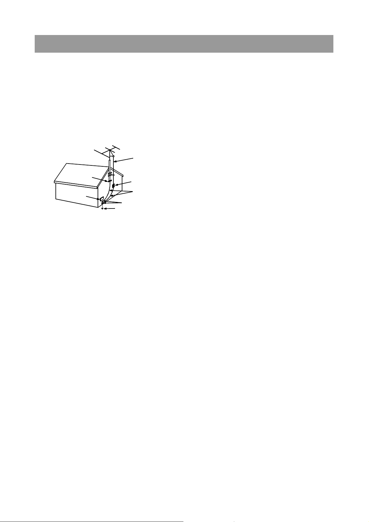
13.Outdoor Antenna Grounding - If an outside antenna is
connected to the receiver be sure the antenna system is
grounded so as to provide some protection against voltage
surges and built-up static charges. Article 810 of the National
Electrical Code, ANSI/NFPA 70, provides information with
regard to proper grounding of the mast and supporting
structure, grounding of the lead-in wire to an antenna-dis
charge unit, size of grounding conductors,location of antennadischarge unit, connection to grounding electrodes and
requirements for the grounding electrode. See Figure 1.
14.Non-use Periods - The power cord of the appliance should be
unplugged from the outlet when left unused for a long period
of time.
15.Object and Liquid Entry - Care should be taken so that objects
do not fall and liquids are not spilled into the enclosure through
openings.
16.Damage Requiring Service - The appliance should be
serviced by qualified service personnel when:
a) The power-supply cord or the plug has been damaged; or
b) Objects have fallen, or liquid has been spilled into the
appliance; or
c) The appliance has been exposed to rain; or
d) The appliance does not appear to operate normally or
exhibits a marked change in performance; or
e) The appliance has been dropped, or the enclosure
damaged.
17.Servicing - The user should not attempt to service the
appliance beyond that described in the operating instructions.
All other servicing should be referred to qualified service
personnel.
ANTENNA DISCHARGE UNIT
(NEC SECTION 810-20)
ANTENNA LEAD
IN WIRE
POWER SERVICE GROUNDING
ELECTRODE SYSTEM
(NEC ART 250 PART H)
GROUND CLAMP
ELECTRIC
SERVICE
EQUIPMENT
GROUNDING CONDUCTORS
(NEC SECTION 810-21)
GROUND CLAMPS
EXAMPLE OF ANTENNA
GROUNDING
NEC - NATIONAL ELECTRICAL CODE
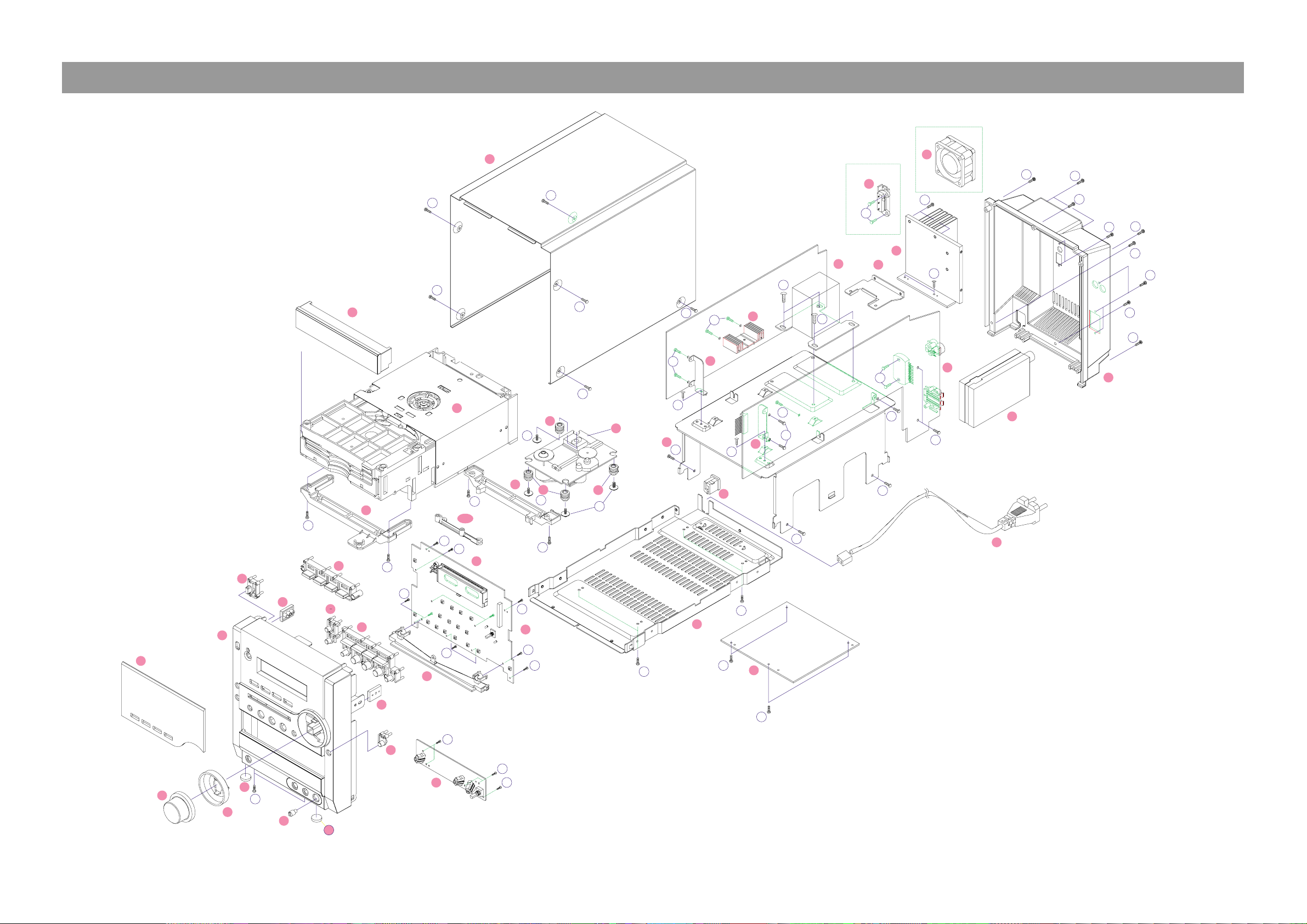
ExplodedViewandMechanicalPartsList
4
3
2
5
5
P2
8
10
1
10
9
7
6
11
1
P1
13
14
19
15
32
22
P3
29
27
P5
P4
25
23
24
21
26
31
28
20
4
12
30
17
18
16
17
7
1
33
14-1
S5
S5
S5
S5
S5
S5
S3
S5
S5
S5
S5
S5
S5
S2
S5
S5
S5
S3
S6
S2
S7
S7
S4
S4
S4
S4
S4
S4
S4
S1
S1
S1
S1
S1
S1
S1
S1
S1
S1
S4
S3
S3
S3
S3
S3
S2
S2
S3
S8
S8
S8
S4
S2
S2

ExplodedViewandMechanicalPartsList
5
No. Part Code Remark
1 WINDOW FLT 9CD1621900 H/MIRROR 1
2 KNOB VOLUME 9CD1352100 ABS 1
3 DECO VOLUME 9CD1006200 HIPS 1
4 PANELFRONT 9CD0313200 HIPS 1
5 CUSHION FOOT 9CD4207700 URETHAN 2
6 KNOB FUNCTION 9CD1352200 HIPS 1
7 KNOB CONTROL 9CD1352300 ABS 1
7 KNOB DEMO 9CD1352310 HIPS 1
8 KNOB OPEN 9CD1352600 HIPS 1
9 KNOB POWER 9CD1352400 HIPS 1
10 BRACKET SIDE 9CD2416300 HIPS 2
11 DECO LIGHT 9CD1006300 ACRYL 1
12 KNOB MIC 9CD1345500 MIPS 1
13 BRACKET CD F 9CD24164F0 HIPS 1
14 BRACKET CD B 9CD24164B0 HIPS 1
14-1 BRACKET CD M 9CD24164M0 HIPS 1
15 CD DECK MECHA 9CD6012400 CMP-0629 1
16 RUBBER CD CUSHION 9CD420097B0 HIPS 1
17 RUBBER CD CUSHION 9CD420097G0 HIPS 1
18 CD DECK UNIT 9CD6006900 D-73S 1
19 DOOR CD 9CD1814700 HIPS 1
20 AC CORD STOPER 9CD5700500 66NYLON 1
21 COVER CD 9CD0416800 SECC 1.0T 1
22 CHASSIS BOTTOM 9CD0610400 SECC 1.0T 1
23 BRACKET PCB L 9CD24165L0 SECC 1.0T 1
24 BRACKET PCB R 9CD24165R0 SECC 1.0T 1
25 HEATSINK PW 9CD4409700 AL 1
26 HEATSINK 9CD4408700 AL 1
27 TUNER MODULE 9737652001 A'SSY 1
28 COVER BACK 9CD0416700 HIPS 1
29 AC CORD 9736910900 PVC 1
30 VOLTSW 5S30102377 ACRYL 1
31 FAN 9738101700 A'SSY 1
32 TOP COVER 9CD0202700 HIPS 1
33 BRACKET PT 9CD2417700 SECC 1.0T 1
433 434 435
S1 SCREW TAPTTITE 7173261011 TT2 BIN 2.6 X 10 MFZN 15 15 15
S2 SCREW TAPTTITE 7173300611 TT2 BIN 3.0X06 MFZN 10 10 10
S3 SCREW TAPTTITE 7173300811 TT2 BIN 3.0X08 MFZN 11 11 11
S4 SCREW TAPTTITE 7173301011 TT2 BIN 3.0X10 MFZN 14 14 14
S5 SCREW TAPTTITE 7173301012 TT2 BIN 3.0X10 BK 19 19 19
S6 SCREW TAPTTITE 7173301211 TT2 BIN 3.0X12 MFZN 2 2 2
S7 SCREW TAPTTITE 7173400611 TT2 BIN 4.0X6 MFZN 4 4 4
S8 SCREW TAPTTITE 9CD3103600 W/S TT2 BIN 2.6 X 8 4 4 4
No.
P1 1
P2 1
P3 1
P4 1
P5 1
PCB SW
PCB CD
PCB POWER
PCB MAIN
Option
Option
Option
CR Coating
CR Coating
No.
Option
PCB FRONT
Part CodeScrew Type

WiringDiagram
6

BlockDiagram
7
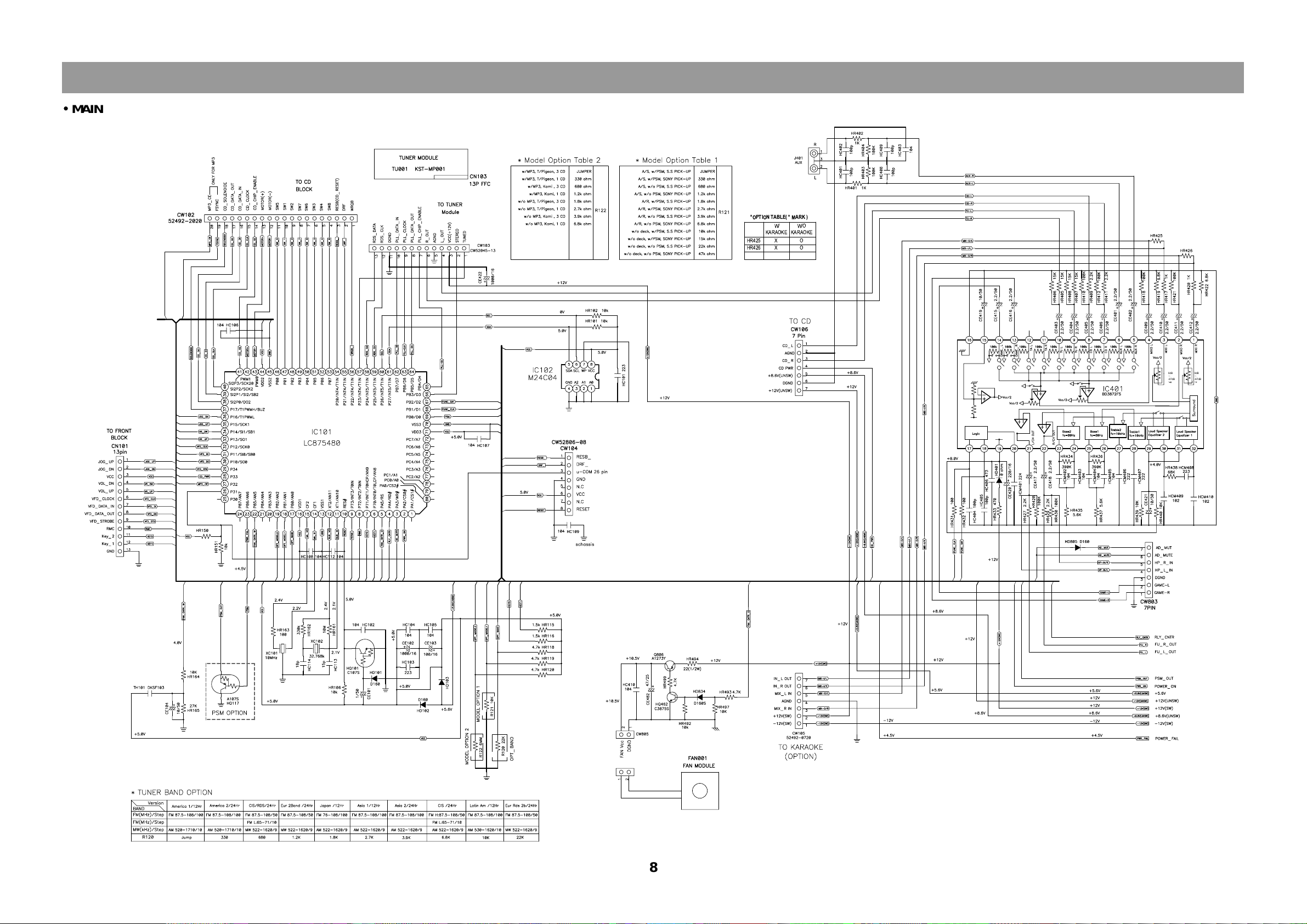
SchematicDiagram
XO
XO
HR425
HR426
W/O
KARAOKE
W/
KARAOKE
*OPTION TABLE( * MARK )
0dB
-87dB
-
0dB
-87dB
-
8
!
MAIN
SchematicDiagram
K2.1
218/118EC
028/418RH
718/518RH
53/0
022
K5
.1K8
.1
001m
ho0
334
)W02(
434
)W03(
05/0
033
mho0
534
)W05(
208CI
060
-334KT
S
05/0
022
NOITPOTUPTUO
*
TIUCRICTCETORP*
030-33
4KTS030-3
34KT
S
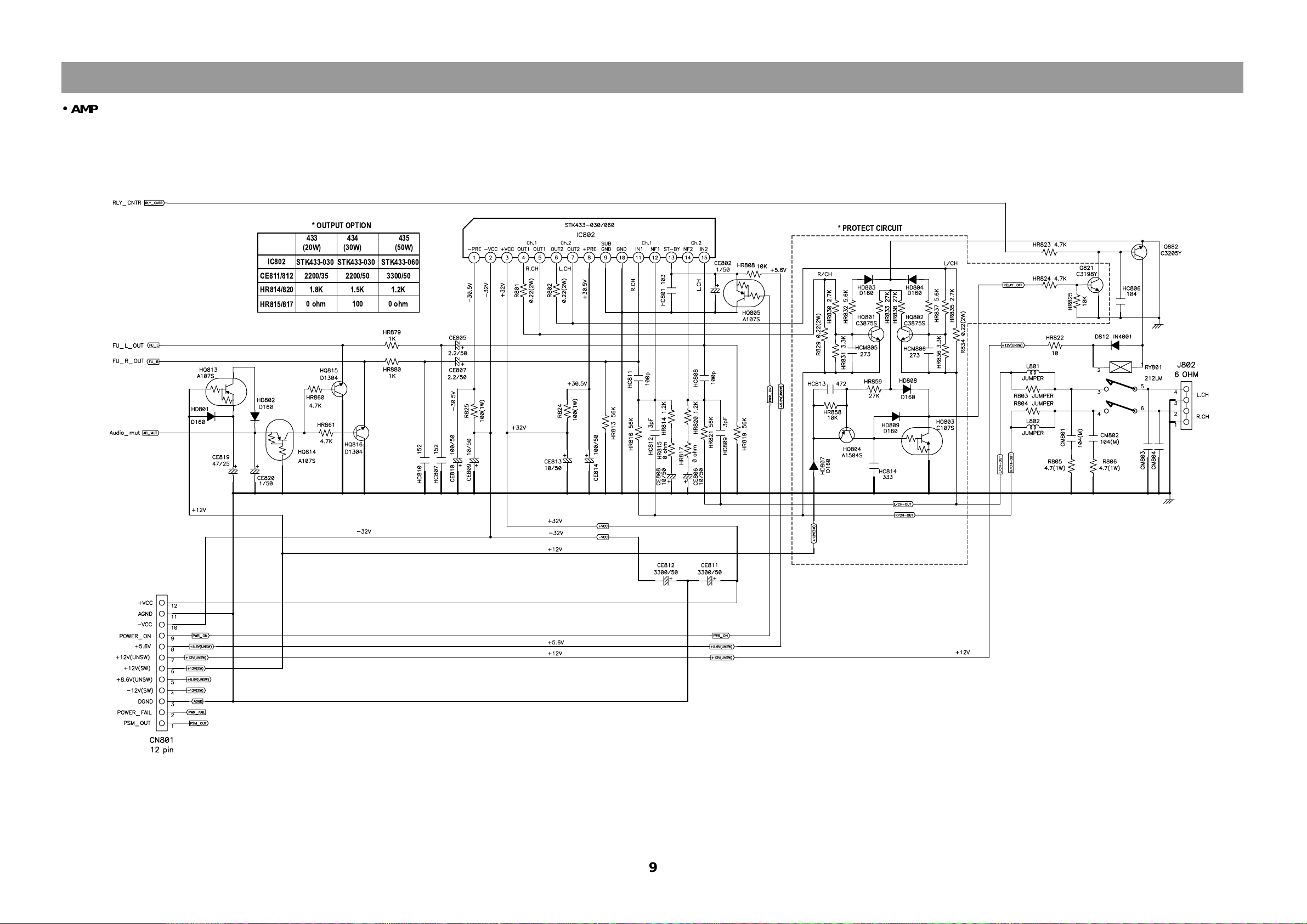
9
!
AMP

SchematicDiagram
10
MP3 CD
 Loading...