


S/M NO. : TSLS00AEF0
Service Manual
LCD TV
CHASSIS :SL-S00A/01A/10A
Model : LA32L1B1LM
LA37L1B1LM
LA42L1B1LM
LA42L1B1LF
Caution
:In this Manual, some parts can be changed for improving. their performance without notice in the parts list. So, if you need the latest parts information, please refer to PPL(Parts Price List)in Service Information Center.
Sep. 2008
Contents
1. |
Safety Precaution................................................................................................................. |
3 |
|
2. |
Preliminary Troubleshooting .............................................................................................. |
4 |
|
3. |
Product Specification .......................................................................................................... |
5 |
|
|
1) |
Standard of Product........................................................................................................... |
5 |
|
2) |
Available Input Signal ........................................................................................................ |
6 |
|
3) |
Closed Caption Specification............................................................................................. |
7 |
|
4) |
V Chip(Parent Control) Specification ................................................................................. |
8 |
4. |
Service Remote Controller.................................................................................................. |
9 |
|
|
1) |
Key Arrangement............................................................................................................... |
9 |
|
2) |
Service Mode Data .......................................................................................................... |
10 |
5. |
Block Diagram .................................................................................................................... |
11 |
|
|
1) |
Block Diagram of Digital Board ........................................................................................ |
11 |
|
2) |
Power Tree ...................................................................................................................... |
12 |
6. |
Hardware Trouble shooting............................................................................................... |
13 |
|
|
1) |
No Picture & No Sound ................................................................................................... |
13 |
|
2) |
No Picture – Analog & Component mode........................................................................ |
14 |
|
3) |
No Picture – Digital TV mode .......................................................................................... |
19 |
|
4) No Picture – PC & HDMI mode ....................................................................................... |
20 |
|
|
5) No Sound......................................................................................................................... |
24 |
|
|
6) |
LCD Panel Backlight Inverter Check ............................................................................... |
25 |
7. |
Schematic ........................................................................................................................... |
26 |
|
8. |
Soft Upgrade Method......................................................................................................... |
42 |
|
9. |
Bill Of Materials.................................................................................................................. |
43 |
|
|
1) |
LA32L1B1LM Parts List ................................................................................................... |
43 |
|
2) |
LA37L1B1LM Parts List ................................................................................................... |
43 |
|
3) |
LA42L1B1LM Parts List ................................................................................................... |
44 |
|
4) |
LA42L1B1LF Parts List.................................................................................................... |
44 |
|
5) |
Common Parts List. ......................................................................................................... |
45 |
10. Mechanical Exploded View ............................................................................................. |
52 |
||
|
1) |
32L1................................................................................................................................. |
52 |
|
2) |
37L1................................................................................................................................. |
53 |
|
3) |
42L1................................................................................................................................. |
54 |

1. Safety Precaution
(1)When moving or laying down a LCD Set, at least two people must work together. Avoid any impact towards the LCD Set.
(2)Do not leave a broken LCD Set on for a long time. To prevent any further damages, after checking the condition of the broken Set, make sure to turn the power (AC) off.
(3)When opening the BACK COVER, you must turn off power (AC) to prevent any electric shock.
(4)When loosening screws, check the position and type of the screw. Sort out the screws and store them separately for reassembling. Because screws holding PCBs are working as electric circuit grounding, make sure to check if any screw is missing when assembling / reassembling. Do not leave any screws inside the set.
(5)A LCD Set contains different kinds of connector cables. When connecting or disconnecting cables, check the direction and position of the cable beforehand.
(6)Connect/disconnect the connectors slowly with care especially FFC (film) cables and FPC cables. Do not connect or disconnect connectors instantaneously with force, and handle them carefully for reassembling.
(7)Connectors are designed so that if the number of pins or the direction does not match, connectors will not fit. When having problem in plugging the connectors, check their kind, position, and direction.
-3-

2.Preliminary Troubleshooting
1)LCD TV does not response or remote controller does not work. - Check the power cord to be plugged.
- Check the battery of the remote controller.
2)Sound is discontinuous or broken sometimes. - Check if [SOUND] -> [AVC] is [ON].
- Set the sound effect into 'F Mono'?
- Set the [SOUND] -> [Digital Volume] into proper value. - [Digital Volume] is enabled only in digital program.
- Check if [SOUND] -> [Speaker] is On.
3)Picture of digital program is sometimes broken and sound is discontinuous.
- Digital program has a little problem because of signal receiving status.
- Check if the RF cable is correctly connected.
- Ask for the broadcasting station if the RF cable connection has no problem.
4)Picture of analog program is noisy. - Check the RF cable connection.
- Check if [Picture] -> [N.R] is ON.
- Change the [Channel] -> [Fine Tune] value.
5)Sound is not generated in HDMI mode. - Reconnect HDMI jack.
- DVI signal has no sound. Check the output signal of device to be connected to LCD TV.
- If you want to use DVI-HDMI cable, you should also connect audio cable into the LCD TV.
6)In spite of 'Auto Setup', picture size is not completely adapted to the screen in PC mode. - Check if the input signal is available.
- Ensure that the desktop has no black area.
- Some errors (picture position problem) will be occurred according to certain video card.
In this case, you should adjust ‘Phase’, ‘Clock’, ‘H.Position’, ‘V.Position’ control.
7)In spite of 'Auto Setup', picture is not clear in the PC mode.
- Adjust 'Phase' control.
-4-
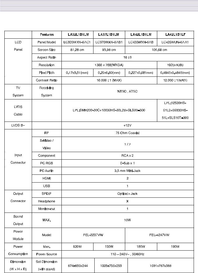
3. Product Specification
1) Standard of Product
Owing to our policy of continuous improvement, specifications may change.
-5-

Product Specification
2)Available Input Signal
i)TVMode
ØColor Standard : NTCS, ATSC
ØReception Channel : Ch 2~13 (VHF), Ch 14~69 (UHF), Ch 1, 14~125(Cable)
ØSound Transmission System : FM Mono, 2 Carrier, Dolby Digital
ØIF &Subcarrier :
G PIF : 45.75MHz
G SIF : 41.25MHz
G Sound Subcarrier : 4.5MHz, 4.72 MHz
G Color Subcarrier : 3.58MHz
GDTV IF : 44MHz (5.38 MHz)
ii)Multimedia Mode
|
Resolution |
V-freq |
HDMI |
PC(D-Sub) |
Component |
Standard |
|
|
|
|
|
|
|
|
|
|
640 X 480 |
60Hz |
O |
O |
X |
VESA Standard |
|
|
|
|
|
|
|
|
|
|
800 X 600 |
60Hz |
O |
O |
X |
VESA Standard |
|
|
|
|
|
|
|
|
|
|
1024 X 768 |
60Hz |
O |
O |
X |
VESA Standard |
|
|
|
|
|
|
|
|
|
|
1280 X 1024 |
60Hz |
O |
O |
X |
VESA Standard |
|
|
|
|
|
|
|
|
|
|
1360 X 768 |
60Hz |
O |
O |
X |
|
|
|
|
|
|
|
|
|
|
|
1600 X 1200 |
60Hz |
O |
O |
X |
|
|
|
|
|
|
|
|
|
|
|
720 X 480i |
60Hz |
X |
X |
O |
|
|
|
|
|
|
|
|
|
|
|
720 X 480p |
60Hz |
O |
O |
O |
|
|
|
|
|
|
|
|
|
|
|
1280 X 720p |
60Hz |
O |
O |
O |
|
|
|
|
|
|
|
|
|
|
|
1920 X 1080i |
60Hz |
O |
O |
O |
|
|
|
|
|
|
|
|
|
|
|
1920 X 1080p |
60Hz |
O |
O |
O |
|
|
|
|
|
|
|
|
|
|
Note :
1.When you connect with component, PC (D-Sub), and HDMI, you must check the input resolution of external devices.
2.So if this mode is used at PC mode, the screen can be enlarged.
3.1600x1200 & 1920x1080P modes are supported only Full HD model.
-6-

Product Specification
3)Closed Caption SPEC
i)DIGITAL(ATSC) standard inspection pattern :
CC708 SPEC STREAM(release to GUMI factory : 2007.02.02)
ii)The Caption feature doesn’t work in COMPONENT, HDMI, and PC modes.
iii)The availability of captions depends on the program being broadcast.
iv)Caption lables and respective meanings.
Ø Analog (NTSC) :
G CC1 : The Primary Synchronous Caption Service.
These are captions in the primary language that must be in sync with the sound, preferably matched to a specific frame.
G CC2 : The Special Non-Synchronous Use Captions.
This channel carries data that is intended to augment information carried in the program.
G CC3 : Secondary Synchronous Caption Service.
Alternate program-related caption data, typically second language captions.
GCC4 : Special Non-Synchronous Use Captions.
Similar to CC2.
ØDigital (ATSC) :
GService 1 : Primary Caption Service This service contains the verbatim,
or near-verbatim captions for the primary language being spoken in the accompanying program audio.
G Service 2 : Secondary Language Service.
This service contains caption in a secondary language
which are translations of the captions in the Primary Caption Service.
G The other service sub-channels are not pre-assigned.
It is up to discretion of the individual caption provider to utilize the remaining service channels.
v)Caption style
ØDefault means to follow the standard set by the broadcaster.
G Text Size : This option consists of Default,Small,Standard,and large. The default is Standard.
G Text Font : This option consists of Default,
Font 1~7.You can change the font you want.
G Text Color : This option consists of Default, White, Black, Red, Green, Blue, Yellow, Magenta, and Cyan.
You can change the color of the letter.The default is White.
G BG Color : This option consists of Default, White, Black, Red, Green, Blue, Yellow,
Magenta, and Cyan. You can change the background color of the caption. The default is Black.
G BG Opacity : This option consists of Default, Rich, Light, and Transparent. You can change the background opacity of the caption.
-7-

Product Specification
4)V Chip(Parental Control) SPEC
i)The rating doesn't work in PIP/POP mode. Reservse case is the same.
ii)The rating setting is possible only on the menu.
iii)Inital password : 2-2-1-1.
iv)Universal key cord (When user does not know password) : 5-4-2-2.
v)The TV Parental Guidelines.
Ø Labels : TV-Y, TV-Y7, TV-G, TV-PG, and TV-14, TV-MA, FV, D, L, S, V
G TV-Y : All Children. Program is designd to be appropriate for all children. G TV-Y7 : Directed to Older Children.
Program is designd for children age 7 and above. G TV-G : General Audience.
This Program contains material that parents ma find suitable to yonger children.
G TV-PG : Parental Guidance Suggested.
This Program contains material that parents may find.
G TV-14 : Parents Strongly Cautioned.
This Program contains some material that many parents wound find unsuitable for children under 14 years of age.
G TV-MA : Mature Audience Only.
This Program is specifically designd to be viewed by adults and therefore may be unsuitable for children under 17.
GFV : Fantasy violence / D : Sexually Suggestive Dialog / L : Adult Language / S : Sexual situation / V : Violence
vi)The Movie ratings
ØLabels : TV-Y, TV-Y7, TV-G, TV-PG, and TV-14, TV-MA, FV, D, L, S, V
GG : General Audiences.All ages admitted.
G PG : Parental Guidance Suggested.
Some material may not be suitable for children. G PG-13 : Parents Strongly Cautioned.
Some material may be inappropriate for children under 13. G R : Restricted.
Under 17 requires accomanying parent or adult guardian. G NC-17 : No children 17 and under admitted.
G X : Adults only. G NR : Not rated.
-8-
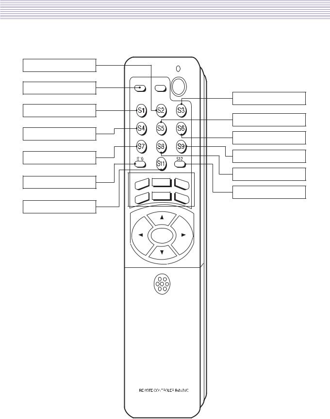
4. Service Remote Controller
1) Key Arrangement |
|
CH Map Save |
|
Recall |
|
|
Volume |
HEAT-RUN |
White Balance |
|
|
No Function |
Auto Calibration |
|
Sound Processor |
Misc |
Hotel mode |
Demodulator |
|
|
|
Factory Reset |
Test Pattern |
|
-9-

Service Remote Controller
2) Service Mode Data
To enter SERVICE MODE,
A.Press “<VOL” -> “MUTE” -> “DISPLAY” -> “MUTE” button of remote controller(R-55M15)
B.Press “S9” button of SERVICE REMOTE CONTROLLER.
-10- |
5.Block Diagram
1)Block Diagram of Digital Board
-11- |

Block Diagram
2) Power Tree
-12- |

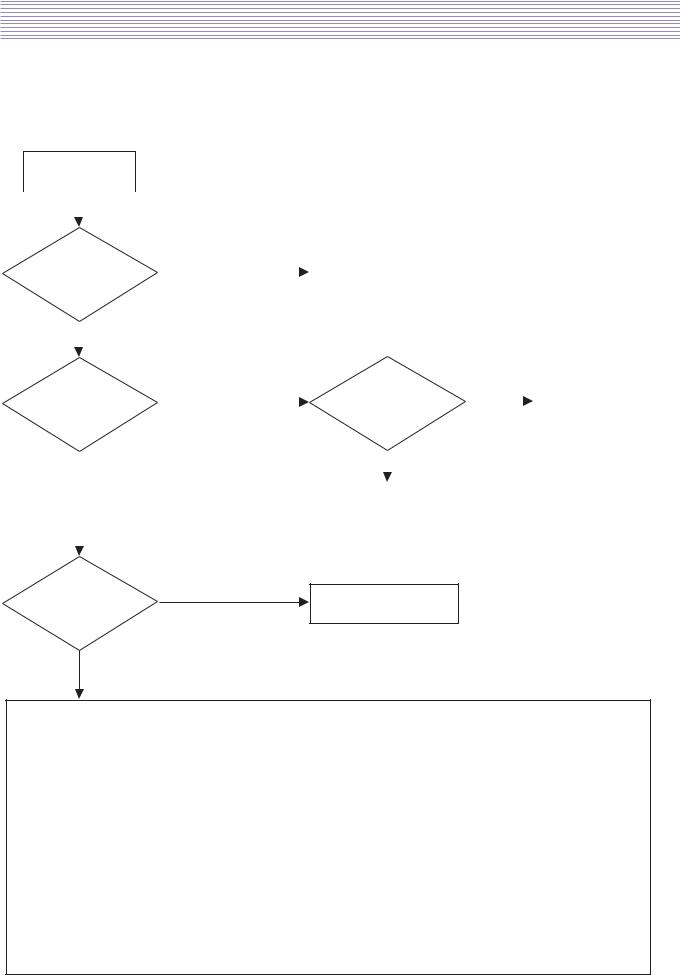
6. Hardware Trouble shooting
1)No picture & No Sound - In case of All mode
START
Yes
Check
Yes
The input power of Digital Board s P801 #14, 15pin 12V is correct
No
Yes
Is the LED is Blinking?
No
No
Check the P801 #11 pin 5V is correct
Yes
Power Board problem
Replace the Power PCB
Check the SMPS and input voltage
IC401 problem.
Replace the Main PCB
Check the #15 pin Cable |
No |
|
Perhaps Connector and |
|
Cable problem. |
||
|
|
||
is correctly connected |
|
|
Replace connector or cable. |
|
|
|
|
Yes
IC401 problem.
Replace the Main PCB
-13-
Hardware Trouble shooting
2)No Picture - Analog & Component mode
- In case of ATV, VIDEO, COMPONENT mode
START
|
Yes |
|
|
|
|
|
|
|
|
|
|
|
|
|
|
|
|
|
|
|
|
|
|
|
|
Check |
No |
|
|
|
|
|
|
|
|
|||
|
Check the SMPS and input voltage |
|
|
|
||||||||
The input power of |
|
|
|
|
|
|
||||||
|
|
|
|
|
|
|||||||
IC401 is correct |
|
|
|
|
|
|
|
|
|
|
||
|
Yes |
|
|
|
|
|
|
|
|
|
|
|
|
|
|
|
|
|
|
|
|
|
|
||
|
|
|
|
|
|
|
|
|
|
|
|
|
|
|
|
|
|
|
|
|
|
|
|
|
|
Check the LVDS signal |
Yes |
|
No |
|
|
Perhaps Connector and |
||||||
|
|
|
Cable problem. |
|||||||||
|
|
|
Check the LVDS signal |
|
|
|
|
|||||
output of IC401 is correct |
|
|
|
output of IC401 is correct |
|
|
|
|
Replace connector or cable. |
|||
|
|
|
|
|
|
|
Yes |
|
|
|
|
|
|
|
|
|
|
|
|
|
|
|
|
|
|
|
|
|
|
|
|
|
|
|
|
|
|
|
|
|
|
|
|
|
|
|
|
|
|
|
|
|
|
|
|
|
|
|
|
|
|
|
|
|
|
No |
|
|
|
IC401 problem. |
|
|
|
|
|
||
|
|
|
|
Replace the Main PCB |
|
|
|
|
|
|||
|
|
|
|
|
|
|
|
|
|
|
||
|
|
|
|
|
|
|
|
|
|
|
|
|
|
|
|
|
|
|
|
|
|
|
|
|
|
Yes
Is the input signal IC401
IC401 problem.
nomal?
Replace the Main PCB
No
1) TV mode: Check the path
TU101(CE102) -> IC202(CC214, RC230) -> IC401(RC226, RC229, QC202, CC218, RC233, CC220, CC221) 2) Component mode: Check the path
Comp1: JK208(LC208-210) -> IC204(CC241, CC243, CC245) -> IC204(RC251, RC252, RC253) -> IC204(RC247 ~ 249) -> IC401(RC237 ~ 239)
Comp2: JK208(LC213-215) -> IC204(CC242, CC244, CC246) -> IC204(RC251, RC252, RC253) -> IC204(RC247 ~ 249) -> IC401(RC237 ~ 239)
3) Composite & S-Video
Composite1: JK201(LC201, CC201, RC201, CC202) -> IC202(CC210) -> IC401(RC226, RC229, QC202,
CC218, RC233, CC220, CC221)
Composite2: P201(LC204, CC207, CC208, RC205) -> IC202(CC212) -> IC401(RC226, RC229, QC202,
CC218, RC233, CC220, CC221)
S-Video: JK202(LC203, CC205, LC202, CC203, CC206, RC204, CC204, RC203) -> IC202(CC211, CE201,
RC216) -> IC401(RC226, RC229, QC202, CC218, RC233, CC220, CC221)
-14-
Hardware Trouble shooting
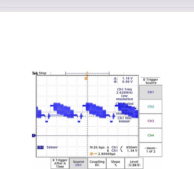
A.When “No signal” in RF, AV1, AV2
1) First check if other inputs are not working
=>If other inputs are not working, replace MAIN PCB
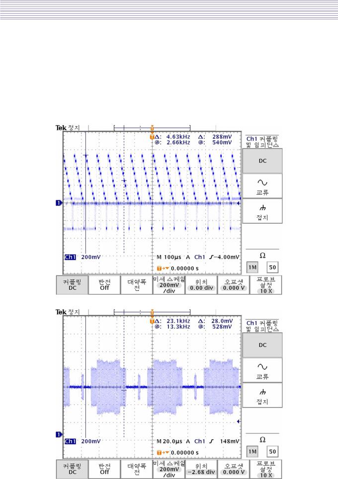
2) Checking waveforms with Color Bar Pattern(Using the oscilloscope) -Main TP(RF) : CC220 near IC401(TOP)
-Main TP(AV1) : CC210 near IC202(TOP)
-Main TP(AV2) : CC212 near IC202(TOP)
=>If all TP signal does not appear, replace MAIN PCB.
CVBS signal(CC220) near IC401(TOP)
-15-
Hardware Trouble shooting
B.When “No signal” in Y/C signal (S-Video)
1)First check if other inputs are not working
=>If other inputs are not working, replace MAIN PCB
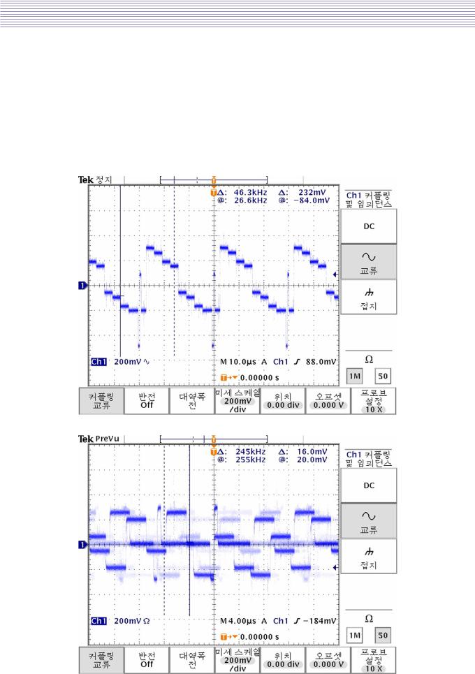
2)Checking waveforms with Color Bar Pattern(Using the oscilloscope) -Main TP(S-Video_Y) : CC211 near IC202(TOP)
-Main TP(S-Video_C) : RC216 near IC202(TOP)
=>If all TP signal does not appear, replace MAIN PCB.
Y signal(CC211)
C signal(RC216)
-16-
Hardware Trouble shooting
C.When “No signal” in Y/Pb/Pr signal (Component)
1)First check if other inputs are not working
=>If other inputs are not working, replace MAIN PCB
2)Checking waveforms with Color Bar Pattern(Using the oscilloscope) -Main TP(COMP_Y) : RC238 near IC401(TOP)
-Main TP(COMP_Pb) : RC237 near IC401(TOP)
-Main TP(COMP_Pr) : RC239 near IC401(TOP)
=> If all signal does not appear, replace MAIN PCB.
Y signal(RC238)
Pb signal(RC237)
-17-
 Loading...