


S/M No. : TMECHA
Service Manual
VCR MECHANISM UNIT
(T-MECHA DECK)
DAEWOO ELECTRONICS CO., LTD.
http : //svc.dwe.co.kr |
Feb. 2000 |

CONTENTS |
|
1. ASSEMBLY DIAGRAM AND A/S............................................................................................ |
2 |
2. WIRE DIAGRAM........................................................................................................................ |
5 |
3. PERIODIC MAINTENANCE AND SERVICE SCHEDULE .................................................... |
6 |
4. SERVICE SCHEDULE FOR THE MAJOR PARTS ................................................................ |
7 |
5. JIGS AND TOOLS..................................................................................................................... |
8 |
6. DEASSEMBLY AND REPLACEMENT ................................................................................. |
10 |
7. MECHANICAL ADJUSTMENT.............................................................................................. |
16 |
8.ADJUSTMENT OF THE TAPE TRANSPORTING SECTION .............................................. |
19 |
9. EXPLODED VIEW AND PARTLIST ....................................................................................... |
25 |
1

ASSEMBLY DIAGRAM AND A/S
1.Assembly diagram
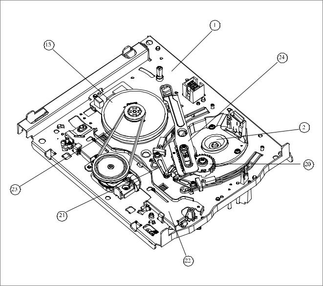
1-1. DECK Assembly diagram A. Upper View
fig1-1 |
1 |
MAINBASE ASS’Y |
9 |
IDLER PLATE TOTAL ASS’Y |
17 |
AC HEAD ASS’Y |
2 |
DRUM ASS’Y |
10 |
T BRAKE ASS’Y |
18 |
T SLANT POLE ASS’Y |
3 |
FE HEAD |
11 |
FL RACK |
19 |
HEAD CLEANER |
4 |
S SLANT POLE ASS’Y |
12 |
RELAY LEVER |
|
|
5 |
TENSION BAND ASS’Y |
13 |
CAPSTAN MOTOR |
|
|
6 |
S BRAKE ASS’Y |
14 |
LC BRKT ASS’Y |
|
|
7 |
S REEL TABLE |
15 |
PINCH LEVER TOTAL ASS’Y |
|
|
8 |
REEL BRKT TOTAL ASS’Y |
16 |
CAM GEAR |
|
|
2
ASSEMBLY DIAGRAM AND A/S (CONTINUED)
B. Lower View
|
fig1-2 |
20 |
L LOADING ASS’Y |
21 |
R LOADING ASS’Y |
22 |
CONNECT PLATE |
23 |
REEL BELT |
24 |
LOADING RACK |
|
3 |
ASSEMBLY DIAGRAM AND A/S (CONTINUED)
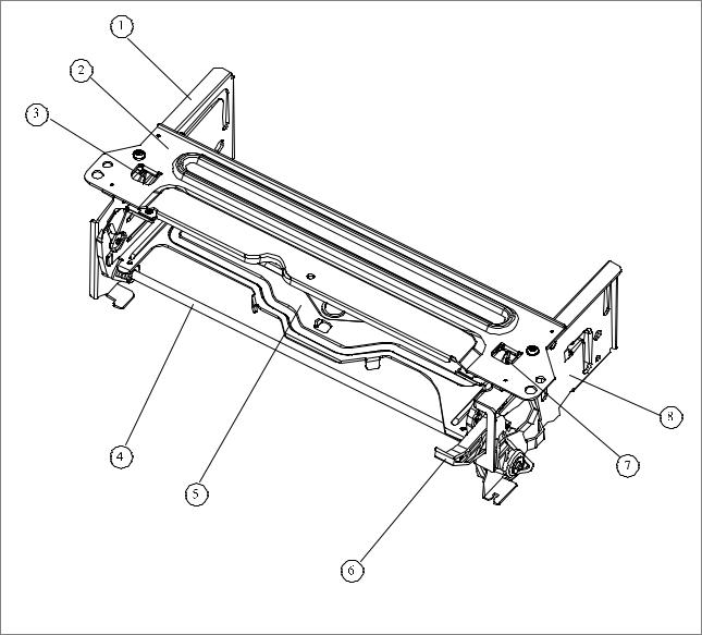
1-2. FRONT LOADING Assembly diagram
fig2 |
1 |
FL BRKT L |
5 |
CST HOLDER AS |
2 |
TOP PLATE |
6 |
DOOR OPENER |
3 |
SAFETY LEVER |
7 |
SAFETY LEVER R |
4 |
LOADING LEVER AS4 |
8 |
FL BRKT R |
4
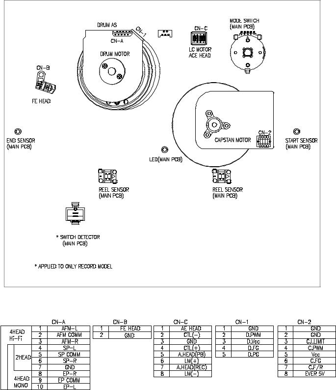
WIRE DIAGRAM
1. Wire Diagram
2. Connector Pin Arrangement
5
PERIODIC MAINTENANCE AND SERVICE SCHEDULE
1.PERIODIC MAINTENANCE AND SERVICE SCHEDULE
A.In order to effectively maintain the excellent performance and fully utilize the features of this apparatus, and to lengthen the life of the mechanism and tapes, we strongly urge you to perform periodic maintenance and inspection, as described below.
*After repairing, do the maintenance described below, irrespective of the length of time in use.
B.Cleaning of the Head Drum Ass'y
-Clean the Drum assembly with a cleaning cloth soaked in liquid cleaner (alcohol) by placing lightly against the Drum and slowly revolving the rotating HEAD DRUM Ass'y by hand (Do not rotate the upper Drum by applying electric power to the motor when cleaning).
-Do not move the cleaning cloth in the vertical direction against the heat-tip.
C.Cleaning the tape transporting section.
-Clean the tape transporting parts with a cleaning cloth soaked in alcohol.
D.Cleaning of driving section
-Clean the driving section with a cloth soaked in alcohol.
E.Routine inspection
-Perform maintenance and inspection as separately described depending on the period of time in use.
-Refer to the table of 2-2-3.
-After cleaning with alcohol, allow the parts to dry thoroughly before using a cassette tape.
b.Cleaning of Driving section
•REEL TABLE
•CAPSTAN FLYWHEEL/PULLEY
•REEL PULLEY
B.LUBRICATION
•S REEL POST
•T REEL TABLE POST
•REEL GEAR POST
-After cleaning these parts with alcohol, lubricate these with one or two drops of oil.
2. CLEANING AND LUBRICATION
A. Cleaning of Tape Transporting section and Driving section a. Cleaning of Tape Transporting section
-The following parts should be cleaned after every 500 hours of use.
• TENSION POLE |
• S SLANT POLE |
• AC HEAD/AE HEAD |
• S GUIDE POST |
• VIDEO HEAD/DRUM |
• T GUIDE POST |
• FE HEAD |
• T SLANT POLE |
• CAPSTAN SHAFT |
• S GUIDE ROLLER |
• T GUIDE ROLLER |
• PINCH ROLLER |
•VERTICAL POST
-As the above parts contact with the video tape, they tend to collect dust particles. If they are stained with dust or foreign substance it has a bad effect on the picture and may lead to damage of the tape.
6
SERVICE SCHEDULE FOR THE MAJOR PARTS
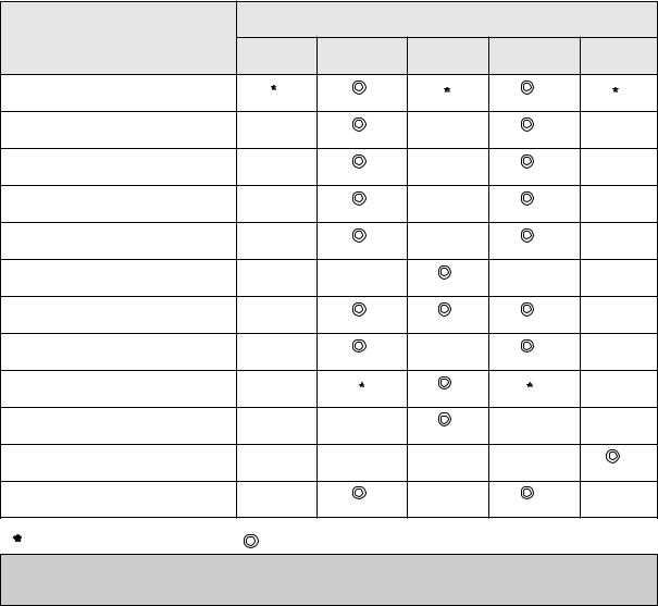
SERVICE SCHEDULE FOR THE MAJOR PARTS
The following parts should receive periodic service, according to the recommended intervals.
NAME |
PERIODIC SERVICE (TIME) |
|
||
|
|
|
|
|
1000 |
2000 |
3000 |
4000 |
5000 |
DRUM TOTAL ASS'Y |
|
|
|
|
CAPSTAN MOTOR |
|
|
|
|
L/C BRKT TOTAL ASS'Y |
|
|
|
|
REEL BELT |
|
|
|
|
IDLER PLATE TOTAL ASS'Y |
|
|
|
|
REEL TABLE |
|
|
|
|
TENSION BAND ASS'Y |
|
|
|
|
S, T BRAKE ASS'Y |
|
|
|
|
PINCH ROLLER ASS'Y |
|
|
|
|
AC HEAD ASS'Y |
|
|
|
|
FE HEAD |
|
|
|
|
REEL GEAR TOTAL ASS'Y |
|
|
|
|
: Check and Replace if necessary. |
: Replace |
Note: Even though the unit is not used frequently, cleaning, lubrication and replacement of the belt should be undertaken every 2 years.
7
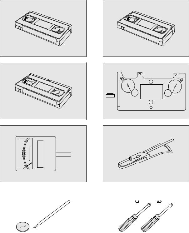
JIGS AND TOOLS
1. List of Jigs and Tools
NO |
ITEMS |
MODEL |
FIG. |
REMARKS |
|
N O |
|
||||
|
|
|
|
|
|
|
|
|
|
|
|
|
|
NTSC: SP MONOSCOPE 7KHz |
|
CHECKING OF THE |
|
1 |
ALIGNMENT TAPE |
SP COLORBAR 1KHz |
! |
TAPE TRANSPORTING |
|
|
|
(EP MONOSCOPE) |
|
SYSTEM |
|
|
|
PAL/SCAM: SP MONOSCOPE 6KHz |
|
|
|
|
|
SP COLORBAR 1KHz |
|
|
|
|
|
(LP MONOSCOPE) |
|
|
|
|
|
|
|
|
|
2 |
CLEANING TAPE |
DHC-602V |
@ |
CHECKING OF THE TAPE |
|
(DAEWOO) |
TRANSPORTING SYSTEM |
|
|||
|
|
|
|
||
|
|
|
|
|
|
3 |
CASSETTE TAPE |
KT-300NV |
# |
MEASUREMENT OF |
|
(KOKUSAI) |
KT-300RV |
REEL TORQUE |
|
||
|
|
|
|||
|
|
|
|
|
|
4 |
VHS SPINDLE |
TSH-V4 |
$ |
MEASUREMENT OF |
|
HEIGHT GAUGE |
REEL HEIGHT |
|
|||
|
|
|
|
||
|
|
|
|
|
|
5 |
TENTELO METER |
T2-H7-UM |
% |
MEASUREMENT OF |
|
(TENTELO) |
THE BACK TENSION |
|
|||
|
|
|
|
||
|
|
|
|
|
|
|
FAN TYPE |
|
|
MEASUREMENT OF THE |
|
6 |
TENSION METER |
BELOW 3KG |
^ |
PRESSING FORCE FOR |
|
|
|
|
|
THE PINCH ROLLER |
|
|
|
|
|
|
|
7 |
DENTAL MIRROR |
|
& |
CHECKING OF THE TAPE |
|
|
TRANSPORTING SYSTEM |
|
|||
|
|
|
|
|
|
|
|
|
|
|
|
8 |
+DRIVER |
|
*-1 |
ASSEMBLY, |
|
|
|
|
|
DISASSEMBLY |
|
|
|
|
|
|
|
|
ADJUSTMENT DR IVER |
|
*-2 |
AND ADJUSTMENT |
|
|
|
|
|
|
|
8
JIGS AND TOOLS(CONTINUED)
2. Sketch of Jigs and Tools
! @
ALIGNMENT |
TAPE |
CLEANING |
TAPE |
|
|
#
%
$ |
|
|
|
|
|
|
|
|
30 |
|
|
20 |
30 |
|
|
|
|
20 |
|
|
|
||
|
|
|
|
|
|
||
30 |
|
10 |
VHS SPINDLE |
10 |
|
30 |
|
20 |
10 |
0 |
HEIGHT GAUGE |
0 |
10 |
||
20 |
|||||||
^ |
|
|
|
|
|
|
& |
|
* |
|
|
|
9
DEASSEMBLY AND REPLACEMENT
1.Removal of the FRONT LOADING Ass’y (Fig. 3.1)
NOTE:
Remove the FRONT LOADING Ass’y in eject mode.
a.Unscrew the 2 screw holding the F/L.
b.Separate the F/L Ass’y from the MAINBASE settling down point by lifting the rear part of F/L (Screw Hole).
Fig. 3.1 Removal of the FRONT LOADING Ass’y |
2.Deassembly of FRONT LOADING Ass’y (FIg. 3.2~3.5)
a.Remove the 1 washer for holding the door opener and separate F/L Assembly by moving the DOOR OPENER in the direction of arrow.
b.Remove the 2 screw holding the TOP PLATE and separate the CASSETTE HOLDER Ass’y by moving the FL BRKT L and FL BRKT R in the direction of arrow. (Fig. 3.2)
FIg. 3.2 Deassembly of the FRONT LOADING Ass’y |
c.Separate the FL LIFT SPRING by twisting and dragging from FL BRKT R. (Fig. 3.3)
FIg. 3.3 Deassembly of the FL BRKT Ass’y |
10
 Loading...