


 Loading...
SERVICE MANUAL
LCD Television
CHASSIS : SLV65E
Model : DSL-15C1T

SLV65E TFT LCD TV
CONTENTS
1. |
INTRODUCTION ..................................................................................................................................... |
5 |
||
|
1.1 |
Scope................................................................................................................................................... |
|
5 |
|
1.2 |
Description.......................................................................................................................................... |
|
5 |
2. |
ELECTRICAL REQUIREMENTS ........................................................................................................... |
5 |
||
|
2.1 |
Standard Test Conditions.................................................................................................................... |
5 |
|
|
|
2.1.1 |
MEASUREMENT SYSTEMS........................................................................................ |
6 |
|
2.2 |
LCD DISPLAY General Specification ................................................................................................ |
6 |
|
|
2.3 |
LCD Panel Specification .................................................................................................................... |
7 |
|
|
|
2.3.1 |
LCD Panel Model............................................................................................................ |
7 |
|
|
2.3.2 |
Optical Characteristics .................................................................................................... |
8 |
|
2.4 |
Input Signals ..................................................................................................................................... |
12 |
|
|
|
2.4.1 |
VGA input ................................................................................................................... |
12 |
|
|
2.4.2 |
Sync input...................................................................................................................... |
12 |
|
|
2.4.3 |
Interface frequency........................................................................................................ |
12 |
|
|
2.4.4 |
Support Modes............................................................................................................... |
14 |
|
|
2.4.5 |
Video input Connector .................................................................................................. |
14 |
|
|
2.4.6 |
STANDARD ACCESSORIES...................................................................................... |
15 |
|
2.5 |
CONTROLS....................................................................................................................................... |
16 |
|
|
|
2.5.1 |
OSD Functions .............................................................................................................. |
17 |
|
2.6 |
White Color Temperature ................................................................................................................. |
18 |
|
|
2.7 |
POWER SUPPLY: PK100V0140I OR PK100V0180I ...................................................................... |
19 |
|
|
|
2.7.1 |
Input Voltage Range...................................................................................................... |
19 |
|
|
2.7.2 |
Input Frequency Range.................................................................................................. |
19 |
1

|
2.7.3 |
Quick specification review ............................................................................................ |
19 |
|
2.7.4 |
Power Management ....................................................................................................... |
20 |
|
2.7.5 |
Power Consumption ...................................................................................................... |
20 |
|
2.7.6 |
Power Connector ........................................................................................................... |
20 |
2.8 |
Plug & Play (EDID) ......................................................................................................................... |
20 |
|
2.9 |
Audio Technical specification........................................................................................................... |
21 |
|
|
2.9.1 |
General Description: ...................................................................................................... |
21 |
|
2.9.2 |
Electrical characteristics (Tamb=25 ° ) ........................................................................... |
21 |
|
2.9.3 |
Speakers ......................................................................................................................... |
21 |
|
2.9.4 |
Headphone output .......................................................................................................... |
21 |
3. MECHANICAL REQUIREMENTS ....................................................................................................... |
22 |
||
3.1 |
Vibration and Shock.......................................................................................................................... |
22 |
|
|
3.1.1 |
Non - Operating ............................................................................................................... |
22 |
3.2 |
Package Drop Specification ............................................................................................................. |
22 |
|
|
3.2.1 |
Drop Test Sequence ....................................................................................................... |
22 |
3.3 |
Dimension Size and Weight .............................................................................................................. |
23 |
|
3.4 |
Gap Spec. |
.......................................................................................................................................... |
23 |
|
3.4.1 . ................ |
The step between front bezel and back cover shall be within specification |
23 |
|
3.4.2 .......................................................................................................... |
LCD Horizontally |
24 |
|
3.4.3 ............................................. |
Gap between panel with bezel is 0.2 mm < gap <1.5 mm |
25 |
3.5 |
Tilt Base Rotation ............................................................................................................................. |
25 |
|
3.6 |
Plastic Material ................................................................................................................................ |
25 |
|
4. Power Line Transient ........................................................Test (IEC 61000-4-4 Fast Transients/Burst) |
25 |
||
4.1 |
Peak Voltage ..................................................................................................................................... |
26 |
|
4.2 |
Polarity ............................................................................................................................ |
: + / - |
26 |
4.3 |
Repetition ....................................................................................Frequency of the impulse: 5 KHz |
26 |
|
4.4 |
Rise-Time .................................................................................................................... |
: 5ns ± 30% |
26 |
2

|
4.5 |
Impulse Duration: 50 nS ± 30% ....................................................................................................... |
26 |
|
|
4.6 |
Relation to Power Supply: Asynchronous ........................................................................................ |
26 |
|
|
4.7 |
Burst Duration: 15 ms ± 20%........................................................................................................... |
26 |
|
|
4.8 |
Burst Period: 300 ms ± 20%............................................................................................................. |
26 |
|
|
4.9 |
Climatic Conditions .......................................................................................................................... |
26 |
|
|
4.10 |
Test Procedure.................................................................................................................................. |
26 |
|
5. Power Line Surge Test (IEC 61000-4-5 Surge)....................................................................................... |
27 |
|||
|
5.1 |
Climatic Condition............................................................................................................................ |
28 |
|
|
|
5.1.1 |
Ambient Temperature: 15 ° C to 35 ° C ............................................................................ |
28 |
|
|
5.1.2 |
Relative Humidity: 10% to 75% .................................................................................... |
28 |
|
|
5.1.3 |
Atmospheric Pressure 86kPa (860 mbar ) to 106kPa (1060mbar) ................................ |
28 |
|
5.2 |
Test Conditions:................................................................................................................................ |
28 |
|
|
|
5.2.1 |
Wave - shape of the current surge: (refer to IEC 61000 - 4 - 5) .......................................... |
28 |
|
|
5.2.2 |
Polarity: positive / negative ........................................................................................... |
28 |
|
|
5.2.3 |
Phase shifting: in a range between 0º to 270º versus the AC line phase angle ............. |
28 |
|
|
5.2.4 |
Repetition rate: at least 1 per minute ............................................................................. |
28 |
|
|
5.2.5 |
Number of tests: at least 5 positive and 5 negative at the selected points . .................... |
28 |
|
5.3 |
The surge will be applied between lines and between lines and ground.......................................... |
28 |
|
6. |
ENVIROMENT REQUIREMENT ......................................................................................................... |
28 |
||
|
6.1 |
Operating |
.......................................................................................................................................... |
29 |
|
6.2 |
Storage or ..........................................................................................................................Shipment |
29 |
|
|
|
6.2.1 .................................................................................................... |
TEST PROCEDURE: |
29 |
7. |
REGULATION .............................................................................................................COMPLIANCE |
30 |
||
|
7.1 |
This product ...........................complies with the most current revisions of following regulations: |
30 |
|
|
7.2 |
Electrostatics ........................................................................................................Discharge (ESD) |
31 |
|
3

8. |
QUALITY AND RELIABILITY ............................................................................................................ |
32 |
|
|
8.1 |
QUALITY ASSURANCE ................................................................................................................... |
32 |
|
8.2 |
RELIABILITY.................................................................................................................................... |
32 |
9. |
APPANDIX A: P.C.B.A ASSEMBLY...................................................................................... |
33 |
|
10 |
APPANDIX B: DISPLAY UNIT ASSEMBLY ........................................................................ |
55 |
|
4

1.INTRODUCTION
1.1Scope
This specification defines the requirements for the 15” MICRO-PROCESSOR based Multimode supported high resolution color LCD DISPLAY, This LCD DISPLAY can be directly connected to general 15 pin D-sub VGA connector, eliminates the requirement of optional special display card. It also supports VESA DPMS power management and plug & play function. There is a build-in stereo audio amplifier with volume control to drive a pair of speakers.
1.2 Description
The LCD DISPLAY is designed with the latest LCD technology to provide a performance oriented product with no radiation. This will alleviate the growing health concerns. It is also a space saving design, allowing more desktop space, and comparing to the traditional CRT monitor, it consumes less power and gets less weight in addition MTBF target is 20k
hours or more.
2. ELECTRICAL REQUIREMENTS
2.1 Standard Test Conditions
All tests shall be performed under the following conditions, unless otherwise specified.
Ambient light: |
225 lux |
Viewing distance: |
50 cm in front of LCD panel |
Warm up time |
|
All specifications: |
30 minutes |
Fully functional: |
5 seconds |
Measuring Equipment: |
Chroma 2225 signal generator or equivalent, directly |
|
connected to the monitor under test. |
|
Minolta CA110 photometer, or equivalent |
Control settings |
|
User brightness control: |
Maximum (unless otherwise specified) |
User contrast control : |
Typical (unless otherwise specified) |
User red/white balance, |
|
Green/white balance and |
|
Blue/white balance control: |
In the center (unless otherwise specified) |
Power input: |
110Vac or 230Vac |
Ambient temperature: |
20 ± 5 ˚C ( 68 ± 9 ˚ F) |
Analog input mode: |
1024x768 /60 Hz |
5

2.1.1 MEASUREMENT SYSTEMS
The units of measure stated in this document are listed below: 1 gamma = 1 nano tesla
1 tesla = 10,000 gauss cm = in x 2.54
lb = kg x 2.2
degrees F = [°C x 1.8] + 32 degrees C = [°F - 32]/1.8 u' = 4x/(-2x + 12y + 3)
v' = 9y/(-2x + 12y + 3)
x = (27u'/4)/[(9u'/2) - 12v' + 9] y = (3v')/[(9u'/2) - 12v' + 9]
nits = cd/(m2) = Ft-L x 3.426 lux = foot-candle x 10.76
2.2 LCD DISPLAY General Specification
Panel Type : |
38.1cm( 15 ") active matrix color TFT LCD |
||
Display size : |
1). CPT CLAA150XP03 |
||
304.1mm(H) x 228.1mm(V) |
|||
Display mode : |
TN mode, Normally White |
||
|
VGA |
720 X 400 |
(70 Hz) |
|
VGA |
640 X 480 |
(60/66/70/72/75 Hz) |
|
SVGA |
800 X 600 (60/70/72/75 Hz) |
|
Pixel pitch : |
XGA |
1024 X 768 (60/70/75 Hz) |
standard resolution |
0.297mm(H) x 0.297mm(V) |
|
||
Display Dot : |
1024 x (RGB) x 768 |
|
|
Pixel Clock : |
25 – 81 MHz |
|
|
Contrast ratio: θ = 0˚ |
500 : 1 |
(typical) |
|
Brightness: |
400 |
cd/m2 (typical) |
|
Response time (Tr+Tf) : |
16 msec (typical) |
|
|
Display color : |
16.2M (6 bite color+ FRC) |
|
|
Viewing angle: |
L / R 70 / 70 typ. ( 140 degrees horizontal typical) |
||
Luminance Uniformity : |
U / D 60 / 65 typ. ( 125 degrees horizontal typical) |
||
> 80 % (typical) |
|
||
Pc interface: |
Video : |
RGB analog 0.7V peak to peak |
|
Signal connector : |
Sync : |
TTL positive or negative |
|
15 pin Mini D type, (standard VGA video) |
|
||
Audio power : |
2.5Wrms + 2.5Wrms ( 250Hz – 15kHz (S.P.L. – 10 dB)) |
||
Front control : |
power on/off with LED, CH/function select, mode, Menu, |
||
Interface frequency |
Volume/ volume adjustment (+,-) |
|
|
|
|
|
|
Horizontal Frequency |
29KHz --61KHz |
|
|
Vertical Frequency |
55Hz ----75Hz |
|
|
Plug & play : |
Support VESA DDC2B functions |
|
|
Power Input voltage : |
Single phase, 50/60HZ, 100VAC to 240VAC ±10% |
||
Total output power : |
56 Watt max. |
|
|
6

2.3LCD Panel Specification
2.3.1LCD Panel Model
• |
Display Type |
TN active matrix color TFT LCD |
• |
Resolution |
V:768 lines , H:1024 pixels |
• |
Display Dot |
1024 x (RGB) x 768 |
• |
Display Area |
304.128mm(H) x 228.096mm(V) |
• |
Pixel Pitch |
0.297mm(H) x 0.297mm(V) |
• |
Display Color |
6-bits+ FRC driver |
• |
White luminance |
400 cd/m2 typ. |
|
(center of screen) |
|
• |
Contrast Ratio |
500:1(typical) |
• |
Response Time(Tr+Tf) |
(16ms) typ |
• |
Lamp Voltage |
1480V(rms) max. |
• |
Lamp Current |
6.5 mA (rms) typ. |
• |
View Angle (Hor./Ver.) |
70°(L),70°(R) / 60°(H), 65°(L). typ. |
|
|
(Contrast Ratio 10) |
• |
Brightness uniformity |
80 % (typical) |
• |
Weight |
1,350g. max |
7

2.3.2 Optical Characteristics
Item |
|
Symbol |
Condition |
Min. |
Typ. |
Max. |
Unit |
Note |
|
|
|
|
|
|
|
|
|
Contrast |
|
CR |
|
400 |
500 |
- |
|
(1)(2) |
|
|
|
|
|
|
|
|
|
Response |
Rising |
TR |
|
- |
Tr+Tf |
- |
|
|
time |
|
|
|
|
=16 |
=24 |
msec |
(1)(3) |
Falling |
TF |
|
- |
|||||
|
|
|
|
|||||
|
|
|
|
|
|
|
|
|
White Luminance |
TL |
|
300 |
400 |
- |
Cd/m2 |
|
|
(center of screen) |
|
|
||||||
|
|
|
|
|
|
|
||
|
|
|
θ=0 |
|
|
|
|
|
|
|
RX |
0.613 |
0.643 |
0.673 |
|
|
|
|
|
Φ=0 |
|
|
||||
|
Red |
|
Normal |
|
|
|
|
|
|
|
|
|
|
|
|
||
|
|
RY |
Viewing |
0.305 |
0.335 |
0.365 |
|
|
|
|
Angle |
|
|
||||
|
|
|
|
|
|
|
|
|
|
|
GX |
|
0.267 |
0.297 |
0.327 |
|
|
Color |
Green |
|
|
|
|
|
|
|
|
|
|
|
|
|
|
||
chromaticity |
|
GY |
|
0.558 |
0.588 |
0.618 |
|
(1)(4) |
(CIE1931) |
|
|
|
|||||
|
|
|
|
|
|
|
|
|
|
|
BX |
|
0.112 |
0.142 |
0.172 |
|
|
|
Blue |
|
|
|
|
|
|
|
|
BY |
|
0.048 |
0.078 |
0.108 |
|
|
|
|
|
|
|
|
||||
|
|
|
|
|
|
|
|
|
|
|
WX |
|
0.249 |
0.313 |
0.309 |
|
|
|
White |
|
|
|
|
|
|
|
|
Wy |
|
0.299 |
0.329 |
0.359 |
|
|
|
|
|
|
|
|
||||
|
|
|
|
|
|
|
|
|
Viewing |
|
θL |
|
60 |
70 |
- |
|
|
Angle |
Hor. |
|
|
|
|
|
|
|
θR |
|
60 |
70 |
- |
|
|
||
|
|
|
|
|
||||
|
|
|
CR>10 |
|
|
|
Degree |
|
|
|
ΦH |
50 |
60 |
- |
|
||
|
|
|
|
|
||||
|
Ver. |
|
|
|
|
|
|
|
|
ΦL |
|
55 |
65 |
- |
|
|
|
|
|
|
|
|
||||
|
|
|
|
|
|
|
|
|
Brightness Uniformity |
BUNI |
θ=0 |
75 |
80 |
- |
% |
(5) |
|
|
|
|
Φ=0 |
|
|
|
|
|
Crosstalk |
|
CT(N) |
- |
- |
1.2 |
|
|
|
|
|
% |
(6) |
|||||
|
|
|
|
|
|
|
||
Note (1) Definition of Viewing Angle:
8
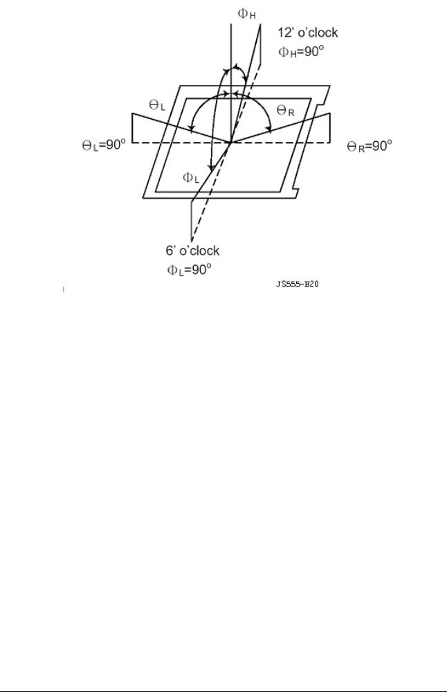
Note (2) Definition of Contrast Ratio (CR):
Measured at the center point of panel
Luminance with all pixels white (L63)
CR= ———————————————
Luminance with all pixels white (L0)
9

Note (3) Definition of Response Time: Sum of TR and TF
Note (4) Optical characteristic measurement setup
10
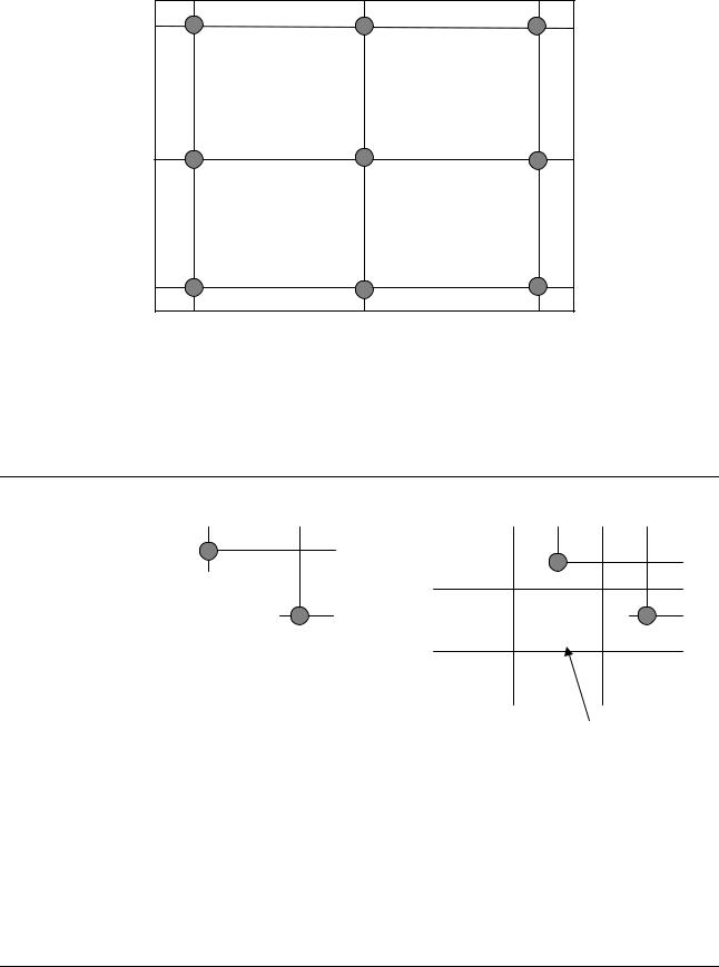
Note (5) Brightness is measured at the center point of brightness value with all pixels displaying white.
90 % |
50 % |
10 % |
10 %
50 %
90 %
Unit: percentage of dimension of display area
Note 5: Brightness uniformity of these 9 points is defined as below: (Min. brightness / Max. brightness) x 100%
Note 5:
|
|
|
|
|
|
|
|
|
|
|
|
|
|
|
|
|
|
|
|
|
|
|
|
|
|
|
|
|
|
|
|
|
|
|
|
|
|
|
|
|
|
|
|
|
|
|
|
|
|
|
|
|
|
|
|
|
|
|
|
|
|
|
|
|
|
|
|
|
|
|
|
|
|
|
|
|
|
|
|
|
|
|
|
|
|
|
|||
184 |
|
|
|
|
184 |
|
|
|
||||||
|
gray |
|
|
|
|
|
gray |
|
||||||
|
|
|
|
|
|
|
|
|
|
|
|
|
|
|
0 gray level
Unit: percentage of dimension of display area
l LA-LA’ l / LA x 100%= 1.2% max., LA and LB are brightness at location A and B
l LB-LB’ l / LB x 100%= 1.2% max., LA’ and LB’ are brightness at location A’ and B’
11

2.4 Input Signals
AV1(CVBS,S-VIDEO),AV2(Y,Cb,Cr/Y,PB,PR) INPUTS
Composite |
Type |
Composite |
: NTSC/PAL |
Video |
Level |
0.7Vpp |
|
|
|
||
|
Impedance |
75 ohm terminated |
|
S-Video |
Type |
Y/C |
: NTSC/PAL |
|
Level |
0.7Vpp |
|
|
Impedance |
75 ohm terminated |
: |
|
|
|
|
Component |
Type |
Y , Cb ,Cr |
: NTSC/ PAL |
|
|
Y,PB,PR |
1080I/720P/480P 60HZ |
|
Level |
0.7Vpp |
|
|
Impedance |
75 ohm terminated |
|
2.4.1 VGA input
• |
Type |
Analog R, G, B. |
• |
Input Impedance |
75 ohm +/- 2% |
• |
Polarity |
Positive |
• |
Amplitude |
0 - 0.7V –0.035V/+ 0.07 V |
• |
Display Color |
same as LCD panel |
2.4.2 Sync input
• |
Signal |
separate horizontal and vertical sync, or composite sync |
|
|
which are TTL compatible |
• |
Polarity |
positive and negative. |
2.4.3 Interface frequency
The following frequency range is generalized by supported timing. If the entered mode does not match the supported timing the display optimization will not be
assured. |
|
|
• |
Horizontal Frequency |
29KHz --61KHz |
• |
Vertical Frequency |
55Hz ----75Hz |
12

Supported Timing
|
FH(KHZ) |
SYNC |
TOTAL |
ACTIVE |
SYNC |
FRONT |
BACK |
PIXEL |
TIMING |
FV(HZ) |
POLARITY |
(DOT/LINE) |
(DOT/LINE) |
WIDTH |
PORCH |
PORCH |
FOREQ.(MHZ) |
|
|
|
|
|
(DOT/LINE) |
(DOT/LINE) |
(DOT/LINE) |
|
|
|
|
|
|
|
|
|
|
640x350 |
31.469 |
+ |
800 |
640 |
96 |
16 |
48 |
25.175 |
VGA-350 |
70.087 |
– |
449 |
350 |
2 |
37 |
60 |
|
640x400 |
24.83 |
– |
848 |
640 |
64 |
64 |
80 |
21.05 |
NEC PC9801 |
56.42 |
– |
440 |
400 |
8 |
7 |
25 |
|
640x400 |
31.469 |
– |
800 |
640 |
96 |
16 |
48 |
25.175 |
VGA-GRAPH |
70.087 |
+ |
449 |
400 |
2 |
12 |
35 |
|
640x400 |
31.5 |
– |
800 |
640 |
64 |
16 |
80 |
25.197 |
NEC PC9821 |
70.15 |
– |
449 |
400 |
2 |
13 |
34 |
|
640x480 |
31.469 |
– |
800 |
640 |
96 |
16 |
48 |
25.175 |
VGA-480 |
59.94 |
– |
525 |
480 |
2 |
10 |
33 |
|
640x480 |
37.861 |
– |
832 |
640 |
40 |
16 |
120 |
31.5 |
VESA-480-72Hz |
72.809 |
– |
520 |
480 |
3 |
1 |
20 |
|
640x480 |
37.5 |
– |
840 |
640 |
64 |
16 |
120 |
31.5 |
VESA-480-75Hz |
75 |
– |
500 |
480 |
3 |
1 |
16 |
|
720x400 |
31.469 |
– |
900 |
720 |
108 |
18 |
54 |
28.322 |
VGA-400-TEXT |
70.087 |
+ |
449 |
400 |
2 |
12 |
35 |
|
800x600 |
35.156 |
+ |
1024 |
800 |
72 |
24 |
128 |
36 |
SVGA |
56.25 |
+ |
625 |
600 |
2 |
1 |
22 |
|
800x600 |
37.879 |
+ |
1056 |
800 |
128 |
40 |
88 |
40 |
VESA-600-60Hz |
60.317 |
+ |
628 |
600 |
4 |
1 |
23 |
|
800x600 |
48.077 |
+ |
1040 |
800 |
120 |
56 |
64 |
50 |
VESA-600-72Hz |
72.188 |
+ |
666 |
600 |
6 |
37 |
23 |
|
800x600 |
46.875 |
+ |
1056 |
800 |
80 |
16 |
160 |
49.5 |
VESA-600-75Hz |
75 |
+ |
625 |
600 |
3 |
1 |
21 |
|
1024x768 |
48.363 |
– |
1344 |
1024 |
136 |
24 |
160 |
65 |
XGA |
60.004 |
– |
806 |
768 |
6 |
3 |
29 |
|
1024x768 |
53.964 |
+ |
1328 |
1024 |
176 |
16 |
112 |
71.664 |
COMPAQ-XGA |
66.132 |
+ |
816 |
768 |
4 |
8 |
36 |
|
1024x768 |
56.476 |
– |
1328 |
1024 |
136 |
24 |
144 |
75 |
VESA-768-70Hz |
70.069 |
– |
806 |
768 |
6 |
3 |
29 |
|
1024x768 |
60.023 |
+ |
1312 |
1024 |
96 |
16 |
176 |
78.75 |
VESA-768-75Hz |
75.029 |
+ |
800 |
768 |
3 |
1 |
28 |
|
If the input timing is not a supported timing listed above but within the supported frequency range (Horizontal: 61KHz,Vertical: 75Hz), this monitor will select a closest mode instead. But the display quality may not be optimized.
If the input timing over the supported frequency range, a message “Out of Range” will be shown.
13
2.4.4 Support Modes
There will be 16 total support modes to accommodate the above mode and other video modes within the frequency range of the monitor.
2.4.4.1 PC model control function
Bright , Contrast , Picture position , OSD position , Auto adjustment , Clock , Phase , OSD Transparence , Language , Color Temperature Graphic/Text select
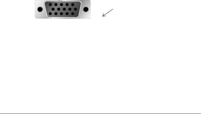
2.4.5 Video input Connector
Analog Video input Connector: 15pins mini D-Sub
Table 2.4.5. Pin assignment for D-sub connector
PIN NO. |
Separate Sync |
|
|
1 |
RED VIDEO |
2 |
GREEN VIDEO |
3 |
BLUE VIDEO |
4 |
GROUND |
5 |
GROUND |
6 |
RED GROUND |
7 |
GREEN GROUND |
8 |
BLUE GROUND |
9 |
PC5V (+5V DDC) |
10 |
CABLE DETECTION |
11 |
GROUND |
12 |
SDA |
13 |
H.SYNC |
14 |
V.SYNC |
15 |
SCL |
Color of plastic parts: Blue
D-sub connector
14

2.4.6 STANDARD ACCESSORIES
ANALOG VGA CABLE
Type |
Worldwide type |
Length |
1.8m + 5cm/-5cm |
Color |
black |
Connectors |
Monitor -side |
POWER CABLE |
|
Type |
Worldwide type |
Length |
1.8m + 5cm/-5cm |
Color |
black |
Connectors |
Monitor -side |
|
Mains-side |
AUDIO STEREO CABLE |
Length |
|
Connector |
EXTERNAL ADAPTER |
|
Type |
Worldwide type |
Length of DC cable |
1.5m + 1.5cm/-0cm |
Color of adapter |
black |
Connectors |
Monitor-side |
|
Mains-side |
15 pin D-Sub Blue compliant with
IEC 320 female
1.8m + 5cm/-5cm
Φ3.5mm plug green housing
Φ2.5mm DC plug IEC 320 male
15
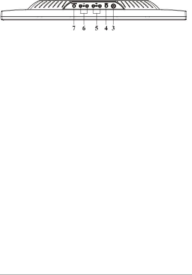
2.5 CONTROLS
Control panel (monitor front panel)
7. Source mode and OSD Menu off function key control.
. Power LED, will be green when monitor is on; be amber when in power saving mode. 6. Adjust decrease and volume control.
. Adjust increase and volume control.
5.activate the OSD and CH Function select counter-clockwise. activate the OSD and CH Function select clockwise.
4. Menu key.
3. Power ON/OFF switch, push to ON and push to OFF. (toggle switch)
16

2.5.1 OSD Functions |
|
|
• |
OSD Format: |
Refer to following figure. |
• |
OSD Border: |
Cyan color |
• |
OSD Tunable Item: |
The 15 icons that around the border. |
• |
Selected Item: |
Yellow background |
• |
Comment: |
Magenta foreground, Blue background |
page format :Monitor function
Description : |
|
|
• |
Brightness: |
Brightness adjustment, the range from 0 to 100. (Def. 100) |
• |
Contrast: |
Contrast adjustment, the range from 0 to 100. (Def. 80) |
• |
H. Position: |
Horizontal position adjustment. |
• |
V. Position: |
Vertical position adjustment. |
• |
Phase: |
focus adjustment, the range from 0 to 100. |
• |
OSD H-position : |
OSD Horizontal position adjustment. |
• |
OSD V-position: |
OSD Vertical position adjustment. |
• |
Auto Adjustment: |
This feature, will automatically adjust size, position, clock and phase. |
• |
Clock: |
Frequency tracking adjustment. The max range from 0 to 100, but |
• |
|
some modes the range will be limited. |
Graph Text: |
640x400(GRAPH) or 720x400(TEXT) mode select. |
|
• |
Language: |
5 kinds of language for description, including (Def. English) |
Recall: |
Recall the default value. |
|
•Color Management: Color temperature/ Color saturation/ Color Hue adjustment.
User:
17

|
|
User R: |
Red signal gain by user defined. |
|
|
User G: |
Green signal gain by user define. |
|
|
User B: |
Blue signal gain by user defined. |
|
|
6500: |
set CIE coordinate at 6500°K color temperature (when use 6500°k |
|
|
|
color temperature, contrast display cannot change and cannot adjust). |
|
|
9300: |
set CIE coordinate at 9300°K color temperature (when use 9300°k |
• |
|
|
color temperature, contrast display cannot change and cannot adjust). |
Save + Exit: |
Save the setting value and exit OSD menu function. |
||
Comment : |
|
||
• |
1024x768: |
Current mode resolution. |
|
• |
75 HZ: |
Current mode vertical frequency. |
|
• |
VER 0.01: |
Firmware revision. |
|
Other features:
Intellectual-Auto LV65E can start the Auto-Adjustment automatically when input a new display mode at first time. After the adjustment, LV65E will remember this mode and
switch to optimized condition automatically for this mode whenever encounter this mode again. Total 16 recent used modes are recorded into EEPROM.
VESA DPMS Functionality When signaled by the host CPU, LV65E shows a black screen about 3 seconds. If no further signal, then it shows “No Signal” and enter power saving mode.
2.6 White Color Temperature
White color temperature is 3 preset as 9300, 6500 and User,
18

User:
User R: Red signal gain by user defined. User G: Green signal gain by user define. User B: Blue signal gain by user defined.
6500: set CIE coordinate at 6500°K color temperature (when use 6500°k
color temperature, contrast display cannot change and cannot adjust).
|
9300: |
set CIE coordinate at 9300°K color temperature (when use 9300°k |
||
|
|
color temperature, contrast display cannot change and cannot adjust). |
||
|
Saturation: |
Color saturation adjustment, the range from 0 to 100. (Def. 100) |
||
|
|
|
|
|
Color Temp. |
9300 |
6500 |
user |
|
x |
|
0.281 |
0.313 |
x1 |
y |
|
0.311 |
0.329 |
y1 |
Tolerance |
+-0.030 |
+-0.030 |
+-0.030 |
|
Note: x1, y1 should meet the color chromaticity of white in panel specification.
2.7 POWER SUPPLY: PK100V0140I OR PK100V0180I
2.7.1 Input Voltage Range
The monitor shall operate within specification over the range of 100 to 240 VAC power supply.
2.7.2 Input Frequency Range
Input power frequency range shall be from 47.5 to 63 Hz over the specified input voltage range.
2.7.3Quick specification review
•Input current: 1.5A (max) at 90VAC input and full load ,
0.75A (max) at 264 VAC input and full load.
• Inrush current @ cold start
30A(0-peak)@ 110Vac ,50A(0-peak) @ 220Vac (measured when switched off for at least 10 mins.)
• |
Output |
|
|
|
|
||
|
|
|
|
|
|
|
|
|
|
|
|
Tolerance |
Output Current |
Volt Tolerance |
|
|
|
|
|
|
|
|
|
|
|
Output Volt |
|
- |
MIN |
MAX |
|
|
|
|
|
|
|
|
|
|
|
+12Vdc |
|
+/-5 % |
0.1A |
5A |
|
• |
|
|
|
|
|
|
|
Total output power: |
48 Watt max. |
|
|
||||
• |
Withstanding voltage : |
1.5Kvac or 2.2KVdc for 1 minute. |
|||||
• |
Leakage current : |
< 0.25mA/100Vac , |
<3.5mA/230Vac |
||||
• |
Efficiency : |
80% min. @115V/230VAC, maximum load. |
|||||
19
Loading...