


S/M No. : C870T0S004
Service Manual
Microwave Oven
Model: KOC-870T0S
KOC-870T5S
KOC-873T0S
KOC-873T5S
Caution
:In this Manual, some parts can be changed for improving, their performance without notice in the parts list. So, if you need the latest parts information,please refer to PPL(Parts Price List) in Service Information Center (http://svc.dwe.co.kr).
DAEWOO ELECTRONICS CO., LTD.
http : //svc.dwe.co.kr |
Aug. 2002 |

PRECAUTIONS TO BE OBSERVED BEFORE AND DURING SERVICING TO AVOID POSSIBLE EXPOSURE TO EXCESSIVE MICROWAVE ENERGY
(a)Do not operate or allow the oven to be operated with the door open.
(b)Make the following safety checks on all ovens to be serviced before activating the magnetron or other microwave source, and make repairs as necessary: (1) Interlock operation, (2) proper door closing, (3) seal and sealing surfaces (arcing, wear, and other damage), (4) damage to or loosening of hinges and latches, (5) evidence of dropping or abuse.
(c)Before turning on microwave power for any service test or inspection within the microwave generating compartments, check the magnetron, wave guide or transmission line, and cavity for proper alignment, integrity, and connections.
(d)Any defective or misadjusted components in the interlock, monitor, door seal and microwave generation and transmission systems shall be repaired, replaced, or adjusted by procedures described in this manual before the oven is released to the owner.
(e)A microwave leakage check to verify compliance with the Federal Performance Standard should be performed on each oven prior to release to the owner.
TABLE OF CONTENTS |
|
PROPER USE AND SERVICE PRECAUTIONS ....................................................................................................................... |
2 |
SPECIFICATIONS....................................................................................................................................................................... |
3 |
NAMES AND FUNCTION OF PARTS........................................................................................................................................ |
4 |
CONTROL PANEL ...................................................................................................................................................................... |
5 |
OPERATION................................................................................................................................................................................ |
7 |
INTERLOCK MECHANISM FUNCTIONS AND ADJUSTMENTS ............................................................................................. |
8 |
PRECAUTIONS FOR DISASSEMBLY AND REPAIR ............................................................................................................. |
10 |
DISASSEMBLY AND ASSEMBLY............................................................................................................................................ |
11 |
TROUBLE SHOOTING GUIDE ................................................................................................................................................ |
20 |
MEASUREMENT ...................................................................................................................................................................... |
27 |
COMPONENT TEST PROCEDURE ........................................................................................................................................ |
29 |
WIRING DIAGRAM ................................................................................................................................................................... |
30 |
SCHEMATIC DIAGRAM ........................................................................................................................................................... |
31 |
EXPLODED VIEWS AND PARTS LIST ................................................................................................................................... |
34 |
PRINTED WIRING BOARD (KOC-870T) ................................................................................................................................ |
37 |
P.C.B. CIRCUIT DIAGRAM (KOC-870T) ................................................................................................................................. |
44 |
P.C.B. LOCATION NO (KOC-870T) . ....................................................................................................................................... |
45 |
PRINTED WIRING BOARD (KOC-873T) ................................................................................................................................ |
47 |
P.C.B. CIRCUIT DIAGRAM (KOC-873T) ................................................................................................................................. |
54 |
P.C.B. LOCATION NO (KOC-873T) . ....................................................................................................................................... |
55 |
1

PROPER USE AND SERVICE PRECAUTIONS
1.For Safe Operation
Damage that allows the microwave energy (that cooks or heats the food) to escape will result in poor cooking and may cause serious bodily injury to the operator.
IF ANY OF THE FOLLOWING CONDITIONS EXIST, OPERATOR MUST NOT USE THE APPLIANCE. (Only a trained service personnel should make repairs.)
1)A broken door hinge.
2)A broken door viewing screen.
3)A broken front panel, oven cavity.
4)A loosened door lock.
5)A broken door lock.
The door gasket plate and oven cavity surface should be kept clean.
No grease, soil or spatter should be allowed to build up on these surfaces or inside the oven.
DO NOT ATTEMPT TO OPERATE THIS APPLIANCE WITH THE DOOR OPEN. The microwave oven has concealed switches to make sure the power is turned off when the door is opened. Do not attempt to defeat them.
DO NOT ATTEMPT TO SERVICE THIS APPLIANCE UNTIL YOU HAVE READ THIS SERVICE MANUAL.
2.For Safe Service Procedures.
1)This microwave oven weight 19kg (38.9 lbs.) and must be placed on a horizontal base strong enough to support this weight.
2)The oven should be placed as far from high temperature source and vapour as possible.
3)The power supply cord is about 1.1m (3.6ft) long. Earthing is required when connecting the power source.
4)Maximum power consumption of this oven is approximately 2.6Kw(230V). It is suggested that the unit is operated on such power line (about 13 amperes) that can provide more power than this rating.
5)Object must not be placed on the top enclosure so as not to obstruct air flow for ventilation.
WARNING : This appliance must be earthed.
IMPORTANT
The wires in this mains lead coloured in accordance with the following code.
Green-and-yellow : Earth
Blue |
: Neutral |
Brown |
: Live |
As the colours of the wires in the mains lead of this appliance may not correspond with the coloured markings identifying the terminals in your plug, proceed as follows:
The wire which is coloured green-and-yellow must be connected the the terminal in the plug which is marked with the letter ‘E’ or by earth symbol or green-and-yellow.
The wire which is coloured blue must be connected to the terminal which is marked with the letter ‘N’ or coloured black.
The wire which is coloured brown must be connected to the terminal which is marked with the letter ‘L’ or coloured red.
NOTE : This oven is designed for counter-top use only.
2

SPECIFICATIONS
MODEL |
KOC-870T0S/873T0S |
KOC-870T5S/873T5S |
||
|
|
|
|
|
POWER SUPPLY |
230V ~ , 50Hz |
240V~, 50Hz |
230V~, 50Hz |
|
|
|
|
|
|
MICROWAVE |
POWER CONSUMPTION |
1,550 W |
1,550 W |
1,550 W |
|
|
|
|
|
|
OUTPUT POWER |
900 W (IEC 705) |
900W(IEC 706) |
900 W (IEC 705) |
|
|
|
|
|
|
FREQUENCY |
2,450 MHZ |
2,450MHz |
2,450MHz |
|
|
|
|
|
GRILL POWER CONSUMPTION |
1,150 W |
1,200 W |
1,150 W |
|
|
|
|
|
|
CONVECTION POWER CONSUMPTION |
1,550 W |
1,600 W |
1,550 W |
|
|
|
|
|
|
AUTO COOK POWER CONSUMPTION |
2,600 W |
2,650 W |
1,550 W |
|
|
|
|
|
|
OUTSIDE DIMENSIONS (W X D X H ) |
501 X 398 X 320 mm (19.7 X 15.7 X 12.6 in.) |
|||
|
|
|
|
|
CAVITY DIMENSIONS (W X D X H) |
310 X 310 X 229 mm (12.2 X 12.6 X 9.0 in.) |
|||
|
|
|
|
|
NET WEIGHT |
|
19 kg (38.9 Ibs.) |
|
|
|
|
|
|
|
TIMER |
|
60 minutes |
|
|
|
|
|
|
|
SELECT FUNCTION |
Microwave/Grill /Convection /Combination |
|||
|
|
|
|
|
MICROWAVE POWER LEVEL |
|
10 stages |
|
|
|
|
|
|
|
* Specifications subject to change without notice.
EXTERNAL VIEWS
|
|
|
|
|
DEFROST |
|
|
|
M/W |
GRILL |
COMBI |
WEIGHT TIME |
|
|
|
|
AUTO |
PIE |
TEMP |
|
kg |
|
|
|
COOK |
|
COOK |
|
|
|
|
Grill |
Combi |
|
+1 min |
|
|
||
Pie |
Temp |
|
+10 sec |
|
|
||
|
|
Auto Cook |
|
|
|||
1. |
Roast Beef |
|
|
|
294 |
320 |
|
2. |
Roast Pork |
|
|
|
|||
3. |
Roast Chicken |
|
|
|
|||
4. |
Fish Fillets |
|
|
|
|||
5. |
Vegetable |
|
|
|
|||
|
|
STOP/ |
|
START |
|||
|
|
CLEAR |
|
|
|||
|
|
|
|
|
|
||
M/W |
|
+ |
Speedy |
|
|
||
|
|
|
|
|
|||
Defrost |
|
|
|
|
|
|
|
|
- |
|
|
|
|
|
|
Clock |
|
|
|
|
|
|
|
|
|
|
TIME/WEIGHT |
|
|
||
332 |
|
|
|
|
|
|
210 |
501 |
|
|
|
|
|
|
402 |
Fig. 1 Front View |
|
|
|
|
|
|
Fig. 2 Side View |
|
|
|
|
|
|
3 |
|

NAMES AND FUNCTION OF PARTS
3 |
|
4 |
5 |
6 |
2 |
|
|
|
|
1 |
9 |
8 |
|
|
|
|
|
DEFROST |
M/W |
GRILL |
COMBI |
WEIGHT TIME |
AUTO |
PIE |
TEMP |
kg |
COOK |
|
COOK |
|
Grill |
Combi |
+1 min |
|
Pie |
|
Temp |
+10 sec |
|
Auto Cook |
7 |
|
1. |
Roast Beef |
|
|
2. |
Roast Pork |
|
|
3. |
Roast Chicken |
|
|
4. |
Fish Fillets |
|
|
5. |
Vegetable |
|
|
|
STOP/ |
|
START |
|
CLEAR |
|
|
M/W |
+ |
Speedy |
|
|
|
||
Defrost
-
Clock
TIME/WEIGHT
8
 10
10
11
1DOOR SEAL - Door seal maintains the microwave within the oven cavity and prevents microwave leakage.
2DOOR HOOK - When door is closed, it will automatically lock shut. If door is opened while oven is operating, magnetron tube will immediately stop operating.
3DOOR SCREEN - Allows viewing of food. Microwave cannot pass through perforations in screen.
4GRILL HEATER - Turns on when grill and simultaneous cooking is selected.
5OVEN LAMP - Automatically turns on during oven operating.
6 SAFETY INTERLOCK SYSTEM
7 CONTROL PANEL
8TURNTABLE TRAY - Rotates during cooking and ensure even distribution of Microwaves. It can also be used as a cooking utensil.
9
0ROTATING BASE - This fits over the shaft in the center of the oven’s cavity floor. This is to remain in the oven for all cooking. It should only be removed for cleaning.
q UNDER HEATER
4

CONTROL PANEL
KOC-870T
When blinking, the oven is operating in COMBI cooking.
When blinking, the oven is operating in GRILL
When blinking, the onve is operating in MICROWAVE COOK
When blinking, the oven is operating in AUTO COOK.
When blinking, the oven is operating in PIE COOK.
When blinking, the oven is operating in CONVECTION (TEMP COOK)
Temp Button Used to set desired temperature. If this button pressed for more than 1.3 seconds, number is scrolled up automatically.
Microwave Button-Used to select the variable microwave power level. If this button is pressed for more than 1.3 seconds, number is scrolled up automatically.
Clock Button-Used to set time.
DEFROST
M/W GRILL COMBI WEIGHT TIME
AUTO |
PIE TEMP |
Kg |
COOK |
COOK |
|
Grill |
Combi |
+1 min |
Pie |
Temp |
+10 sec |
Auto Cook
1.Roast Beef
2.Roast Pork
3.Roast Chicken
4.Fish Fillets
5.Vegetable
STOP/ |
START |
CLEAR |
|
M/W
+ Speedy
Defrost
-
Clock
TIME/WEIGHT
When blinking, the oven is operating in WEIGHT DEFROST.
When blinking, the oven is operating in TIME DEFROST.
When blinking, the oven is operating in weight input mode.
Cooking time is increased by 1 minute.
Cooking time is increased by 10 seconds.
FUNCTION BUTTON Used to select desired oven operation.;Grill, Combi, Pie Temp, Auto Cook, M/W, Defrost.
Stop/Clear Button-Used to select desired oven operation.;Grill, Combi, Pie Temp, Auto Cook, M/W,Defrost.
Start Button-Used to start the selectee cycle.
Speedy Cook Button-
Used to set desired time.
(Time increases by 30 seconds from 30 seconds to 5 minutes.)
Guide Lamp-
When blinking, it informs you to be ready to operate dial knob.
Dial Knob-
Used to set the cooking time, time of day and weight input.
5

CONTROL PANEL
KOC-873T
When blinking, the oven is operating in “Combi” cooking mode.
When blinking, the oven is operating in “Grill” cooking mode.
When blinking, the oven is operating in “Microwave” cooking mode.
When blinking, the oven is operating in “Auto Cook” cooking mode.
When blinking, the oven is operating in “Pie” cooking mode.
Temp Button -Used to set desired temperature. If this button pressed for more than 1.3 seconds, number is scrolled up automatically.
Clock Button - Used to set time.
Microwave Button -
Used to select the variable microwave power level. If this button is pressed for more than 1.3 seconds, number is scrolled up automatically.
Dial Knob- Used to input the cooking time and quantity.
STOP/CLEAR Button - Used to pause and clear all information manually put into the oven.
|
|
|
KOC-873T0S |
|
|
|
|
Defrost |
|
MW Grill |
Combi Weight Time |
|||
Auto |
Pie |
Temp |
Kg |
|
Cook |
Cook |
|||
|
|
|||
Defrost +1min +10sec
Clock Pie Temp
MW
Auto
Grill Cook Combi
Auto Cook Menu
1. Roast beef
2. Roast pork
3. Roast chicken
4. Fish Fillet
5. Vegetable
TIME WEIGHT/QUANTITY
STOP/CLEAR
START/SPEEDY COOK
When blinking, the oven is operating in “Weight Defrost” cooking mode.
When blinking, the oven is operating in “Time Defrost” cooking mode.
When blinking, the oven is operating in weight input mode.
When blinking, the oven is operating in “Convection” cooking mode.
Cooking time is increased by 1 minute.
Cooking time is increased by 10 seconds.
FUNCTION BUTTON-Used to select desired oven operation.
;Grill, Combi, Pie, Temp, Auto Cook, MW, Defrost.
START Button - Used to start the selected cycle.
SPEEDY COOK Button -
Used to program quickly cooking time in 30 seconds increments. (Time increases by 30 seconds from 30 seconds to 5 minutes.)
6

OPERATION
TO STOP THE OVEN WHILE THE OVEN IS OPERATING
1.Press  (STOP / CLEAR) button.
-The  (STOP) indicator starts blinking.
-You can restart the oven by touching  (START) button.
-Touch  once more to erase all instruction except clock.
2.Open the door
-You can restart the oven by closing the door and touching  button.
NOTE : Oven stops operating when door open.
ERASING INSTRUCTIONS
•Touch  (STOP/CLEAR) button to erase all instructions you set previously.
•Opening the oven door during cooking dose not erase cooking instruction.
•If you touch  button during operation, the cooking instructions is all erased.
7
INTERLOCK MECHANISM FUNCTIONS AND ADJUSTMENTS
The door lock mechanism is a device which has been specially designed to completely eliminate microwave radiation when the door is opened during operation, and thus to perfectly prevent the danger resulting from the leakage of microwave.
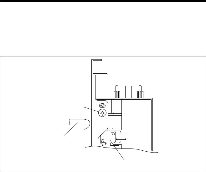
(1) Primary interlock switch
When the door is closed, the hook locks the oven door.
If the door is not closed properly, the oven will not operate.
When the door is closed, the hook pushes the lever downward.
The lever press the button of the primary interlock switch to bring it under ‘ON’ condition.
Mounting screw
Upper Hook
Primary interlock switch
8

(2) Monitor interlock switch
When the door is closed, the hook pushes the lever forward, and pushes the Latch Lever downward the lever press the button of the interlock monitor switch to bring it under ‘OFF’ condition. The latch Lever press the button on the secondary interlock switch to bring it under ‘ON’ condition.
- Adjustment
Interlock monitor switch
When the door is closed, the monitor switch should be opened before other switches close.
When the door is opened, the monitor switch should be closed after other switches open.
Adjustment steps :
a)Loosen the two mounting screws.
b)Adjust the interlock switch assembly position.
c)Make sure that the latch lever moves smoothly after adjustment is completed.
d)Completely tighten the two mounting screws.
9
PRECAUTIONS FOR DISASSEMBLY AND REPAIR
- Cautions to be observed when trouble shooting.
Unlike many other appliances, the microwave oven is high-voltage, high-current equipment. It is completely safe during normal operation. However, carelessness in servicing the oven can result in an electric shock or possible danger from a short circuit.
You are asked to observe the following precautions carefully.
(1)Always remove the power plug from the outlet before servicing.
(2)Use an insulated screwdriver and war rubber gloves when servicing the high voltage side.
(3)Warning about the electric charge in the high voltage capacitor. When inspecting and repairing the high voltage side, always short the capacitor terminals and make sure of discharge.
1. Check the earthing.
Do not operate on a 2-wire extension cord.
The microwave oven is designed to be used when earthed. It is imperative, therefore, to makes sure it is earthed properly before beginning repair work.
2.Warning about the electric charge in the high voltage capacitor.
For about 30 seconds after the operation stops, electric charge remains in the high voltage capacitor. When replacing or checking parts, short between oven chassis and the negative high terminal of the high voltage capacitor, by using a properly insulated screw driver to discharge.
(4)When the 15Amp fuse(870T5S: 12Amp) is blown out due to the operation of the monitor switch; replace secondary interlock switch and monitor switch. Refer to 17 page for the necessary adjustment.
(5)After repair or replacement of parts, make sure that the screws are properly tightened and all electrical connections are tightened.
(6)Do not operate without cabinet.
CAUTION : Service personnel should remove their watches whenever working close to or repairing the magnetron.
WARNING : When servicing the appliance, need a care of touching or replacing high potential parts because of electrical shock or exposing microwave. These parts are as follows - H.V. Transformer, magnetron, H.V. Diode, H.V. Capacitor.
10
DISASSEMBLY AND ASSEMBLY
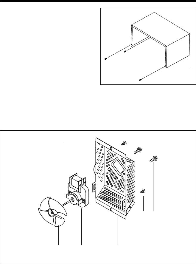
1.To remove cabinet. (Refer to Fig. 1)
1)Remove three screws on cabinet back.
2)Push the cabinet backward.
Fig. 1
2.To remove guide wind assembly. (Refer to Fig. 2)
1)Release two screws .
2)Remove back-cover .
3)Pull the fan to the motor shaft.
4)Release two screws which secure the motor shaded pole .
5)Reverse the above steps for reassembly.
2 1
5 |
4 |
3 |
Fig. 2 |
|
|
|
11
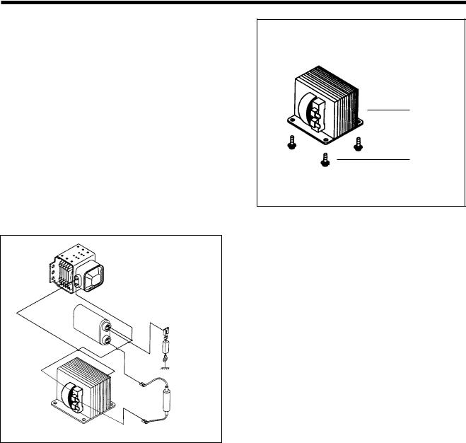
3.To remove H.V. transformer. (Refer to Fig. 3)
1)Remove four screws 1 which secure the H.V. Transformer bracket to the base plate.
2)Remove the H.V. Transformer 2.
2
1
High voltage circuit wiring
Mognetron
H.V. Copacitor
H.V.Diode
H.V. Trans
H.V.Fuse
12
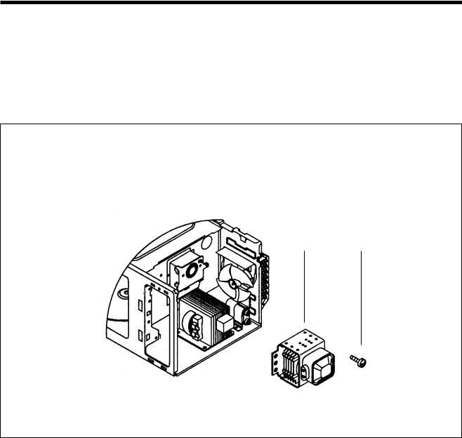
4.To remove magnetron. (Refer to Fig. 4)
1)Remove one screws which secure the magnetron .
2)Remove the magnetron.
3)Reverse the above steps for reassembly.
1 2
Fig. 4
13

CAUTION : Never install the magnetron without the metallic gasket plate which is packed with each magnetron to prevent microwave leakage. Whenever repair work is carried out on magnetron, check the microwave leakage. It shall not exceed 4mW/cm2 for a fully assembled oven with door normally closed.
Metallic |
Magnetron antenna |
Magnetron antenna |
Wave guide |
||
gasket |
|
|
plate |
|
|
Cooling fin
Filament terminal |
Metallic gasket plate |
|
<Magnetron> |
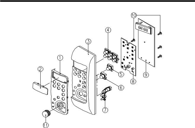
5.To remove control panel assembly. (Refer to Fig. 5, 6)
(1)Remove a screw holding control panel assembly to the oven front plate.
At the same time, draw forward the control panel assembly from oven front plate.
(2)Remove the Dial knob
(3)Remove nine screws which secure the main and sub PCB assembly , to control panel .
(4)Remove buttons , , , .
(5)Remove the Window display , and Decorator Panel .
Fig. 5
14
Caution: In this Service Manual, some parts can be changed for improving, their performance without notice in the parts list. So, if you need the latest parts information, please refer to PPL(Parts Price List) in Service information Center(http://svc.dwe.co.kr)
|
|
|
|
|
Fig. 6 |
|
|
|
|
|
|
|
|
|
|
|
|
REF NO. |
PART CODE |
PART NAME |
DESCRIPTION |
Q’TY |
REMARK |
|
|
|
|
|
|
1 |
3511602500 |
DECORATOR C-PANEL |
ABS |
1 |
KOC-870T(ONLY) |
|
|
|
|
|
|
2 |
3515501300 |
WINDOW DISPLAY |
PMMA |
1 |
KOC-870T0S |
|
|
|
|
|
|
|
3515501320 |
WINDOW DISPLAY |
PMMA |
1 |
KOC-873T0S |
|
|
|
|
|
|
3 |
3516716310 |
CONTROL-PANEL |
ABS |
1 |
KOC-870T0S |
|
|
|
|
|
|
|
3516716370 |
CONTROL-PANEL |
ABS |
1 |
KOC-873T0S |
|
|
|
|
|
|
4 |
3516906000 |
BUTTON FUNCTION(A) |
ABS |
1 |
KOC-870T0S |
|
|
|
|
|
|
|
3516909900 |
BUTTON FUNCTION(A) |
ABS |
1 |
KOC-873T0S |
|
|
|
|
|
|
5 |
3516905900 |
BUTTON FUNCTION(B) |
ABS |
1 |
KOC-870T0S |
|
|
|
|
|
|
|
3516909910 |
BUTTON FUNCTION(B) |
ABS |
1 |
KOC-873T0S |
|
|
|
|
|
|
6 |
3516905800 |
BUTTON FUNCTION(C) |
ABS |
1 |
KOC-870T0S |
|
|
|
|
|
|
|
3516909920 |
BUTTON FUNCTION(C) |
ABS |
1 |
KOC-873T0S |
|
|
|
|
|
|
7 |
3516906100 |
BUTTON FUNCTION(D) |
ABS |
1 |
KOC-870T0S |
|
|
|
|
|
|
|
3516909930 |
BUTTON FUNCTION(D) |
ABS |
1 |
KOC-873T0S |
|
|
|
|
|
|
8 |
PKBPMSQ200 |
PCB SUB ASS’Y |
KOC-970T1S |
1 |
KOC-870T0S |
|
|
|
|
|
|
|
PKBPM00000 |
PCB SUB ASS’Y |
KOC-873T0S |
1 |
KOC-873T0S |
|
|
|
|
|
|
9 |
PKMPMSP700 |
PCB MAIN ASS’Y |
KOC-870T0S |
1 |
KOC-870T0S |
|
|
|
|
|
|
|
PKMPMSP720 |
PCB MAIN ASS’Y |
KOC-870T5S |
1 |
KOC-870T5S |
|
|
|
|
|
|
|
PKMPM00000 |
PCB MAIN ASS’Y |
KOC-873T0S |
1 |
KOC-873T0S |
|
|
|
|
|
|
10 |
7121030811 |
SCREW TAPPING |
T2S PAN 3X8 MFZN |
9 |
KOC-870T0S |
|
|
|
|
|
|
|
7121030811 |
SCREW TAPPING |
T2S PAN 3X8 MFZN |
7 |
KOC-873T0S |
|
|
|
|
|
|
|
7122401211 |
SCREW TAPPING |
T2S PAN 4X12 MFZN |
4 |
KOC-873T0S |
|
|
|
|
|
|
11 |
3513403810 |
KNOB VOLUME |
ABS |
1 |
KOC-870T0S |
|
|
|
|
|
|
|
3513406600 |
KNOB VOLUME |
ABS |
1 |
KOC-873T0S |
|
|
|
|
|
|
15

Caution: In this Service Manual, some parts can be changed for improving, their performance without notice in the parts list. So, if you need the latest parts information, please refer to PPL(Parts Price List) in Service information Center(http://svc.dwe.co.kr)
6.To remove door assembly. (Refer to Fig. 7)
1)Remove two screws 1which secure to hinge.
2)Remove door assembly 2.
3)Remove door above for reassembly taking case to replace fixing glue.
7.To remove door part. (Refer to Fig. 8)
(1)Remove the Gasket door 7.
(2)Remove the Door seal Ass’y 5.
(3)Remove the Hook 8and Spring 9.
(4)Remove the Supporter barri-s *0 3.
(5)Remove the Barrier Screen 2.
(6)Remove the Handle 0from the Frame door 3.
1
2
Fig. 7
|
1 |
2 |
3 |
4 |
5 |
6 |
7 |
|
|
|
|
||||||||||||
|
|
|
|
|
|
|
|
|
|
|
|
|
|
|
|
|
|
|
|
|
8 |
|
|
|
|
|
|
|
|
|
|
|
|
|
|
|
|
|
|
|
|
|
|
|
|
||
|
|
|
|
|
|
|
|
|
|
|
|
|
|
|
|
|
|
|
|
|
|
||
|
|
|
|
|
|
|
|
|
|
|
|
|
|
|
|
|
|
|
|
|
|
||
|
|
|
|
|
|
|
|
|
|
|
|
|
|
|
|
|
|
|
|
|
|
||
|
|
|
|
|
|
|
|
|
|
|
|
|
|
|
|
|
|
|
|
|
|
||
|
|
|
|
|
|
|
|
|
|
|
|
|
|
|
|
|
|
|
|
|
|
||
|
|
|
|
|
|
|
|
|
|
|
|
|
|
|
|
|
|
|
|
|
|
||
|
|
|
|
|
|
|
|
|
|
|
|
|
|
|
|
|
|
|
|
|
|
||
|
|
|
|
|
|
|
|
|
|
|
|
|
|
|
|
|
|
|
|
|
9 |
|
|
|
|
|
|
|
|
|
|
|
|
|
|
|
|
|
|
|
|
|
|
|
|
||
|
|
|
|
|
|
|
|
|
|
|
|
|
|
|
|
|
|
|
|
|
0 |
|
|
|
|
|
|
|
|
|
|
|
|
|
|
|
|
|
|
|
|
|
|
|
|
||
|
|
|
|
|
|
|
|
|
|
|
|
|
|
|
|
|
|
|
|
|
|
q |
Fig. 8 |
|
|
|
|
|
|
|
|
|
|
|
|
|
|
|
|
|
|
|
|
|
|
||
|
|
|
|
|
|
|
|
|
|
|
|
|
|
|
|
|
|
|
|
|
|
|
|
|
|
|
|
|
|
|
|
|
|
|
|
|
|
|
|
|
|
|
|
|
|
||
|
|
|
|
|
|
|
|
|
|
|
|
|
|
|
|
|
|
|
|
|
|
|
|
REF NO. |
PART CODE |
PART NAME |
|
|
|
|
|
|
|
DESCRIPTION |
Q’TY |
REMARK |
|||||||||||
|
|
|
|
|
|
|
|
|
|
|
|
|
|
|
|
|
|
|
|
|
|
||
1 |
3512203520 |
|
FRAME DOOR |
|
|
|
|
|
|
ABS XR-401 |
1 |
KOC-870T0S |
|||||||||||
|
|
|
|
|
|
|
|
|
|
|
|
|
|
|
|
|
|
|
|
|
|
||
|
3512205400 |
|
FRAME DOOR |
|
|
|
|
|
|
PC LUPOY GP-1000 |
1 |
KOC-873T0S |
|||||||||||
|
|
|
|
|
|
|
|
|
|
|
|
|
|
|
|
|
|
|
|
|
|||
2 |
3517004510 |
|
BARRIER-SCREEN*O |
|
|
|
|
GLASS 3.2T |
1 |
KOC-870T0S |
|||||||||||||
|
|
|
|
|
|
|
|
|
|
|
|
|
|
|
|
|
|
|
|
|
|||
|
3517007710 |
|
BARRIER-SCREEN*O |
|
|
|
|
GLASS 3.2T |
1 |
KOC-873T0S |
|||||||||||||
|
|
|
|
|
|
|
|
|
|
|
|
|
|
|
|
|
|
|
|
|
|
||
3 |
3515305300 |
|
SUPPORTER BARRI-S*O |
|
|
|
|
PBT |
|
|
|
|
1 |
KOC-870T(ONLY) |
|||||||||
|
|
|
|
|
|
|
|
|
|
|
|
|
|
|
|
|
|
|
|
|
|||
4 |
3515203600 |
|
STOPPER HINGE*T AS |
|
|
|
|
KOC-970T1S |
1 |
|
|||||||||||||
|
|
|
|
|
|
|
|
|
|
|
|
|
|
|
|
|
|
|
|
|
|
||
5 |
3511709000 |
|
DOOR SEAL AS |
|
|
|
|
|
|
KOC-871C0S |
1 |
|
|||||||||||
|
|
|
|
|
|
|
|
|
|
|
|
|
|
|
|
|
|
|
|
|
|||
6 |
3517004400 |
|
BARRIER-SCREEN*I |
|
|
|
|
GLASS 3.0T |
1 |
|
|||||||||||||
|
|
|
|
|
|
|
|
|
|
|
|
|
|
|
|
|
|
|
|
|
|
|
|
7 |
3512301300 |
|
GASKET DOOR |
|
|
|
|
|
|
PBT |
|
|
|
|
1 |
|
|||||||
|
|
|
|
|
|
|
|
|
|
|
|
|
|
|
|
|
|
|
|
|
|
|
|
8 |
3513101300 |
|
HOOK |
|
|
|
|
|
|
|
|
POM |
|
|
|
|
1 |
|
|||||
|
|
|
|
|
|
|
|
|
|
|
|
|
|
|
|
|
|
|
|
|
|
|
|
9 |
3515101300 |
|
SPRING HOOK |
|
|
|
|
|
|
PW1 |
|
|
|
|
1 |
|
|||||||
|
|
|
|
|
|
|
|
|
|
|
|
|
|
|
|
|
|
|
|
|
|
||
10 |
3512601500 |
|
HANDLE DOOR |
|
|
|
|
|
|
ABS XR-401 |
1 |
KOC-870T(ONLY) |
|||||||||||
|
|
|
|
|
|
|
|
|
|
|
|
|
|
|
|
|
|
|
|
|
|
||
11 |
7122401211 |
|
SCREW TAPPING |
|
|
|
|
|
|
T2S TRS 4X12 MFZN |
2 |
KOC-870T(ONLY) |
|||||||||||
|
|
|
|
|
|
|
|
|
|
|
|
|
|
|
|
|
|
|
|
|
|
|
|
16

8. Method to reduce the gap between the door seal and the oven front surface. |
|
|
|
|
|
(1) To reduce gap located on part ‘A’. |
|
|
|
|
|
1) Remove the cabinet. |
A |
D |
|
|
|
2) Loosen a screw on top door hinge, |
|
|
|
||
|
|
|
|
|
|
then push the door to contact the |
|
|
|
|
|
door seal to oven front surface. |
|
|
|
|
|
3) Tighten a screw. |
|
Grill |
Combi |
+1 min |
|
|
|
Pie |
Temp |
+10 sec |
|
|
|
|
|
Auto Cook |
|
|
|
1. |
Roast Beef |
|
|
|
|
2. |
Roast Pork |
|
|
|
|
3. |
Roast Chicken |
|
|
|
|
4. |
Fish Fillets |
|
|
|
|
5. |
Vegetable |
|
|
|
|
|
STOP/ |
START |
|
|
|
|
CLEAR |
|
|
|
|
M/W |
+ |
Speedy |
|
|
|
|
|
||
|
|
Defrost |
|
|
|
|
|
|
- |
|
|
|
|
Clock |
|
|
|
|
|
|
|
TIME/WEIGHT |
|
|
B |
C |
|
|
|
(2)To reduce gap located on part ‘B’.
1)Loosen a screw on bottom hinge, then push the door to contact the door seal to oven front surface.
2)Tighten a screw.
(3)To reduce gap located on part ‘C’.
1)Remove the cabinet.
2)Loosen a screw on interlock switch assembly located bottom of oven body.
3)Draw the interlock switch assembly inward as possible to engage with hook on the door bottom.
4)Tighten a screw.
(4)To reduce gap located on part ‘D’.
1)Remove the cabinet.
2)Loosen a screw on interlock switch assembly located top of oven body.
3)and 4) are same as step (3).
NOTE : Small gap may be acceptable if the microwave leakage does not exceed 1mW/cm2.
NOTE : The door on a microwave oven is designed to act as an electronic seal preventing the leakage of microwave energy from the oven cavity during the cook cycle. This function does not require that the door be air-tight, moisture (condensation) - Tight or light-tight. Therefore, the occasional appearance of moisture, light or the sensing of gentle warm air movement around the oven door is not abnormal and do not of themselves, indicate a leakage of microwave energy from the oven cavity. If such were the case, your oven could not be equipped with a vent, the very purpose of which is to exhaust the vapor-laden air from the oven cavity.
17
 Loading...