


S/M No. : C1B4K0S002
Service Manual
Microwave Oven
Model: KOC-1B4K0S
KOC-1B4K5S
Caution
:In this Manual, some parts can be changed for improving, their performance without notice in the parts list. So, if you need the latest parts information, please refer to PPL(Parts Price List) in Service Information Center .
Nov. 2005

PRECAUTIONS TO BE OBSERVED BEFORE AND DURING SERVICING TO AVOID POSSIBLE EXPOSURE TO EXCESSIVE MICROWAVE ENERGY
(a)Do not operate or allow the oven to be operated with the door open.
(b)Make the following safety checks on all ovens to be serviced before activating the magnetron or other microwave source, and make repairs as necessary: (1) Interlock operation, (2) Proper door closing, (3) Seal and sealing surfaces (arcing, wear, and other damage), (4) Damage to or loosening of hinges and latches, (5) Evidence of dropping or abuse.
(c)Before turning on power to the microwave oven for any service test or inspection within the microwave generating compartments, check the magnetron, wave guide or transmission line, and cavity for proper alignment, integrity, and connections.
(d)Any defective or misadjusted components in the interlock, monitor, door seal, and microwave generation and transmission systems shall be repaired, replaced, or adjusted by procedures described in this manual before the oven is released to the owner.
A microwave leakage check to verify compliance with the Federal performance standard should be performed on each oven prior to release to the owner.
TABLE OF CONTENTS |
|
1. SAFETY AND PRECAUTIONS.................................................................................................................................... |
2 |
2. SPECIFICATIONS ........................................................................................................................................................ |
3 |
3. EXTERNAL VIEW ......................................................................................................................................................... |
3 |
3-1. OUTER DIMENSION .......................................................................................................................................... |
3 |
3-2. FEATURE DIAGRAM ......................................................................................................................................... |
4 |
4. INSTALLATION ............................................................................................................................................................ |
5 |
5. CONTROL PANEL ....................................................................................................................................................... |
6 |
6. DISASSEMBLY AND ASSEMBLY .............................................................................................................................. |
7 |
7. INTERLOCK MECHANISM AND ADJUSTMENT..................................................................................................... |
17 |
8. TROUBLESHOOTING GUIDE ................................................................................................................................... |
18 |
9. MESUREMENT AND TEST ....................................................................................................................................... |
24 |
9-1. MEASUREMENT OF THE MICROWAVE POWER OUTPUT ........................................................................ |
24 |
9-2. MICROWAVE RADIATION TEST .................................................................................................................... |
25 |
9-3. COMPONENT TEST PROCEDURE................................................................................................................ |
26 |
9-4. COMPONENT ACTION.................................................................................................................................... |
27 |
10. WIRING DIAGRAM................................................................................................................................................... |
28 |
11. EXPLODED VIEW AND PARTS LIST .................................................................................................................. |
29 |
11-1. DOOR ASSEMBLY......................................................................................................................................... |
29 |
11-2. CONTROL PANEL ASSEMBLY..................................................................................................................... |
29 |
11-3. TOTAL ASSEMBLY........................................................................................................................................ |
29 |
12. PRINTED CIRCUIT BOARD .................................................................................................................................... |
33 |
13. P.C.B CIRCUIT DIAGRAM....................................................................................................................................... |
37 |
1

1. SAFETY AND PRECAUTIONS
1. FOR SAFE OPERATION
Damage that allows the microwave energy (that cooks or heats the food) to escape will result in poor cooking and may cause serious bodily injury to the operator.
IF ANY OF THE FOLLOWING CONDITIONS EXIST, OPERATOR MUST NOT USE THE APPLIANCE. (Only a trained service personnel should make repairs.)
1)A broken door hinge.
2)A broken door viewing screen.
3)A broken front panel, oven cavity.
4)A loosened door lock.
5)A broken door lock.
The door gasket plate and oven cavity surface should be kept clean.
No grease, soil or spatter should be allowed to build up on these surfaces or inside the oven. DO NOT ATTEMPT TO OPERATE THIS APPLIANCE WITH THE DOOR OPEN.
The microwave oven has concealed switches to make sure the power is turned off when the door is opened. Do not attempt to defeat them.
DO NOT ATTEMPT TO SERVICE THIS APPLIANCE UNTIL YOU HAVE READ THIS SERVICE MANUAL.
2.FOR SAFE SERVICE PROCEDURES.
1.If the oven is operative prior to servicing, a microwave emission check should be performed prior to servicing the oven.
2.If any certified oven unit is found to servicing, a microwave emission check should be performed prior to servicing the oven.
(a)inform the manufacturer, importer or assembler,
(b)repair the unit at no cost to the owner,
(c)attempt to ascertain the cause of the excessive leakage,
(d)tell the owner of the unit not to use the unit until the oven has been brought into compliance.
3.If the oven operates with the door open, the service person should tell the user not to operate the oven and contact the manufacturer immediately.
IMPORTANT
The wire in this mains lead coloured in accordance with the following code.
Green-and-yellow : Earth
Blue |
: Neutral |
Brown |
: Live |
As the colours of the wires in the mains lead of this appliance may not correspond with the coloured markings identifying the terminals in your plug, proceed as follows.
The wire which is coloured green-and-yellow must be connected to the terminal in the plug which is marked with the letter ‘E’ or by earth symbol or green-and-yellow.
The wire which is coloured blue must be connected to the terminal which is marked with the letter ‘N’ or coloured black.
The wire which is coloured brown must be connected to the terminal which is marked with the letter ‘L’ or coloured red.
NOTE : This oven is designed for counter-top use only.
2
2. SPECIFICATIONS
MODEL |
|
KOC-1B4K0S |
|
KOC-1B4K5S |
|
|
|
|
|
POWER SUPPLY |
|
220~230V~50Hz, SINGLE |
|
220~240V~50Hz, SINGLE |
|
PHASE WITH EARTHING |
|
PHASE WITH EARTHING |
|
|
|
|
||
|
|
|
|
|
|
MICROWAVE |
1500W |
|
|
|
|
|
|
|
POWER |
GRILL |
1600W |
|
|
|
|
|
|
|
CONSUMPTION |
CONVECTION |
2300W |
|
|
|
|
|
|
|
|
COMBINATION |
3100W |
|
2300W |
|
|
|
|
|
MICROWAVE ENERGY OUTPUT |
1000W(IEC705) |
|||
|
|
|
|
|
MICROWAVE FREQUENCY |
2450MHz |
|
||
|
|
|
|
|
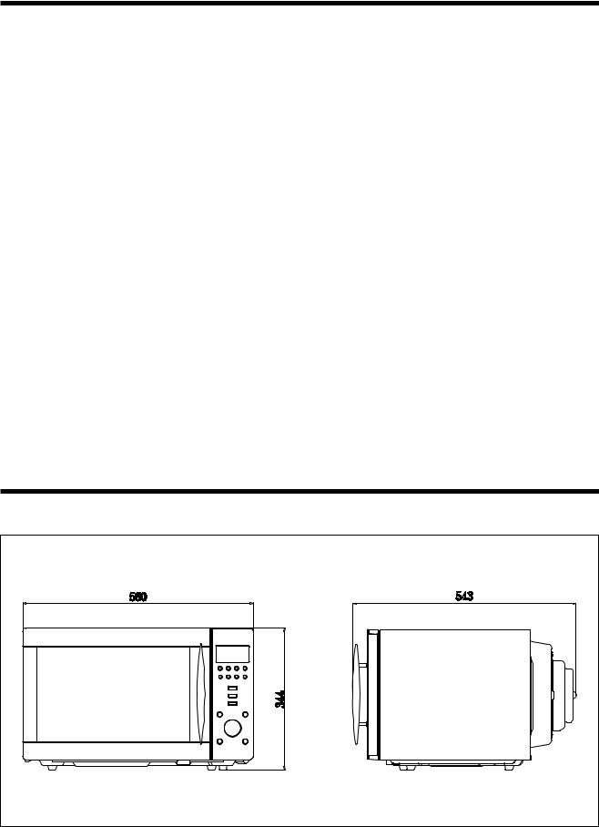
OUTSIDE DIMENSIONS (W X H X D) |
560X344X543mm (22.0X13.5X21.3 in.) |
|||
|
|
|
|
|
CAVITY DIMENSIONS (W X H X D) |
368.5X246X376.5mm (14.5X9.7X14.8 in.) |
|||
|
|
|
|
|
NET WEIGHT |
|
APPROX. 21.5kg (47.6 lbs.) |
||
|
|
|
|
|
TIMER |
|
60 minutes |
|
|
|
|
|
|
|
FUNCTION SELECTIONS |
MICROWAVE/ GRILL/ CONVECTION/ COMBINATION |
|||
|
|
|
|
|
POWER SELECTIONS |
10 LEVELS |
|
||
|
|
|
|
|
CAVITY VOLUME |
|
1.2 Cu. Ft |
|
|
|
|
|
|
|
*Specifications are subject to change without notice.
3.EXTERNAL VIEW
3-1. OUTER DIMENSION |
3 |
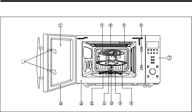
2. FEATURE DIAGRAM
11.DOOR HOOK
When the door is closed, it will automatically lock shut. If door is opened while oven is operating, the magnetron will immediately stop operating.
12.DOOR VIEWING SCREEN
Allows viewing of food. The screen is designed so that light can pass through, but not the microwave.
13.METAL RACK
14.TOP HEATER
Turns on when convection, grill and combi cooking is selected.
15.OVEN LAMP
Automatically turns on during oven operating.
16.SAFETY INTERLOCK SYSTEM
17.CONTROL PANEL
18.TURNTABLE TRAY
Rotates during cooking and ensure even distribution of Microwaves. It can also be used as a cooking utensil.
19.ROLLER GUIDE
This must always be used for cooking together with the turntable tray.
10. COUPLER
This fits over the shaft in the center of the ovens cavity floor. This is to remain in the oven for all cooking.
11.CONVECTION OUTLET & FAN
12.UNDER HEATER
13.OVEN FRONT PLATE
14.DOOR SEAL
Door seal maintains the microwave energy within the oven cavity and prevents microwave leakage.
4

4. INSTALLATION
1.Steady, flat location
This microwave oven should be set on a steady, flat surface. This microwave oven is designed for counter top use only.
2.Leave space behind and side
All air vents should be kept a clearance. If all vents are covered during operation, the oven may overheat and, eventually, cause failure.
3.Away from Radio and TV sets
Poor television reception and radio interference may result if the oven is located close to a TV, Radio, antenna or feeder and so on.
Position the oven as far from them as possible.
4.Away from heating appliances and water taps
Keep the oven away from hot air, steam or splash when choosing a place to position it, or the insulation might be adversely affected and breakdowns occur.
5.Power supply
•Check your local power source. This microwave oven requires a current of approximately 12(8) amperes, 220~240V, 50Hz.
•Power supply cord is about 1.2 meters long.
•The voltage used must be the same as specified on this oven. Using a higher voltage may result in a fire or other accident causing oven damage. Using low voltage will cause slow cooking. We are not responsible for damage resulting from use of this oven with a voltage of ampere fuse other than those specified.
•This appliance is supplied with cable of special type, which, if damaged, must be repaired with cable of same type. Such a cable can be purchased from DAEWOO and must be installed by a Qualified Person.
6.Examine the oven after unpacking for any damage such as:
A misaligned door, broken door or a dent in cavity.
If any of the above are visible, DO NOT INSTALL, and notify dealer immediately.
7.Do not operate the oven if it is colder than room temperature.
(This may occur during delivery in cold weather.) Allow the oven to become room temperature before operating.
EARTHING INSTRUCTIONS
This appliance must be earthed. In the event of an electrical short circuit, earthing reduces the risk of the electric shock by providing an escape wire for the electric current. This appliance is equipped with a cord having a earthing wire with a earthing plug. The plug must be plugged into an outlet that is properly installed and earthed.
WARNING
Improper use of the earthing plug can result in a risk of electric shock. Consult
a qualified electrician or serviceman if the earthing instructions are not completely understood, or if doubt exists as to whether the appliance is properly earthed, and either:
If it is necessary to use an extension cord, use only a 3-wire extension cord that has a 3-blade earthing plug, and a 3-slot receptacle that will accept the plug on the appliance.
The marked rating of the extension cord should be equal to or greater than the electrical rating of the appliance, or Do not use an extension cord.
5

5. CONTROL PANEL
DISPLAY WINDOW
1.MICROWAVE - indicator, showing microwaving in progress.
2. DEFROST- indicator, showing defrosting in progress.
3.GRILL(upper grill heater) - indicator, showing griling in progress.
4.GRILL(lower grill heater) - indicator, showing griling in progress.
5.CONVECTION - indicator, showing convectioning in progress.
6.CHILD LOCK - indicator.
7.% - percentage microwave power level indicator.
BUTTONS
8.language - Press to select the language.
9.clock - Use to set clock.
10.less - Use to remove time from cooking.
11.more - Use to add time to cooking.
12.m/w - Press to select microwave power level.
13.combi - Press to select combi cooking mode.
14.auto defrost - Press to select defrost menu.
15.convection - Press to select convection
temperature.
16.grill - Press to select grill.
17.cake - Press to select cake menu.
18.crusty - Press to select crusty menu.
19.auto cook - Press to select auto cook menu.
20.memory - Use to set favorite cooking mode.
21.start/speedy cook - Press to start a programme, also for speedy start (each press adds 30 secondsmicrowave cooking time).
22.stop/clear - Press once to stop a programme, and twice to cancel a programme.
23.dial knob - Use to set time, weight and quantity.
6
6. DISASSEMBLY AND ASSEMBLY
- Cautions to be observed when trouble shooting.
Unlike many other appliances, the microwave oven is high-voltage, high-current equipment.
It is completely safety during normal operation. However, carelessness in servicing the oven can result in an electric shock or possible danger from a short circuit.
You are asked to observe the following precautions carefully.
1.Always remove the power plug from the outlet before servicing.
2.Use an insulated screwdriver and ware rubber gloves when servicing the high voltage side.
3.Discharge the high voltage capacitor before touching any oven
components or wiring.
(1)Check the earthed.
Do not operate on a two-wire extension cord.
The microwave oven is designed to be used with earthed.
It is imperative, therefore, to makes sure it is earthed properly before beginning repair work.
(2) Warning about the electric charge in the high voltage capacitor. For about 30 seconds after the operation stopped and electric charge remains in the high voltage capacitor. When replacing or checking parts, short between oven chassis and the negative high terminal of the high voltage capacitor, by using a properly insulated screwdriver to discharge.
4.When the 15A fuse is blown out due to the operation of the monitor switch; replace primary interlock switch, secondary interlock switch
and interlock monitor switch. |
SHORT |
5.After repair or replacement of parts, make sure that the screws are properly tightened, and all electrical connections are tightened.
6.Do not operate without cabinet.
CAUTION : Service personnel should remove their watches whenever working close to or replacing the magnetron.
WARNING : When servicing the appliance, need a care of touching or replacing high potential parts because of electrical shock or exposing microwave. These parts are as follows - HV Transformer, Magnetron, HV Capacitor, HV Diode.
7
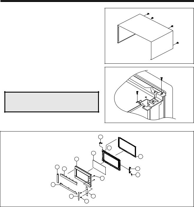
1.To remove: cabinet
1)Remove four screws on cabinet back.
2)Push the cabinet backward.
2. To remove guide wind assembly
1) Remove two screws which secure the stopper hinge top. 2) Remove the door assembly from top plate of cavity.
3) Reverse the above for assemby.
NOTE: After replacting the door assembly, perform a check of correct alignment with the hinge and cavity front plate.
3. To remove door parts.
|
A10 |
|
A11 |
|
A09 |
|
A14 |
|
A07 |
A05 |
A12 |
A04 |
|
|
A13 |
|
A08 |
A03 |
|
A01 |
A06 |
|
A02 |
REF NO. |
PART CODE |
PART NAME |
DESCRIPTION |
Q TY |
REMARK |
A01 |
3512603520 |
HANDLE DOOR |
ALUMINUM |
1 |
|
A02 |
3515307400 |
SUPPORTER HANDLE |
KOC-1B4K0S |
2 |
|
A03 |
3511605500 |
DECORATOR DOOR *U |
STS304 T0.5 |
1 |
|
A04 |
3511605400 |
DECORATOR DOOR *T |
STS304 T0.5 |
1 |
|
A05 |
3511605700 |
DECORATOR DOOR *L |
STS304 T0.5 |
1 |
|
A06 |
3511605600 |
DECORATOR DOOR *R |
STS304 T0.5 |
1 |
|
A07 |
3512204740 |
FRAME DOOR |
PC |
1 |
|
A08 |
7001503511 |
SCREW MACHINE |
PAN 5X35 MFZN |
2 |
|
A09 |
3517004090 |
BARRIER-SCREEN *O |
TEMP GLASS T3.2 |
1 |
|
A10 |
3515204900 |
STOPPER HINGE *T AS |
KOC-1B4K0S |
1 |
|
A11 |
3516602100 |
DOOR-PLATE |
SBHG-1A T0.7 |
1 |
|
A12 |
3513101200 |
HOOK |
POM |
1 |
|
A13 |
3515101800 |
SPRING HOOK |
PW1 |
1 |
|
A14 |
3512302300 |
GASKET DOOR |
PRT |
1 |
|
|
|
|
|
|
|
8
(1)Remove the gasket door from door plate.
(2)Remove a screw from door plate.
(3)Remove the door frame from door plate.
(4)Remove the stopper hinge top from door plate.
(5)Remove the spring and the hook.
(6)Remove two screws from door frame.
(7)Remove the handle door and barrier screen outer from door frame.
(8)Remove the barrier screen outer from handle door.
(9)Reverse the above steps for reassembly.
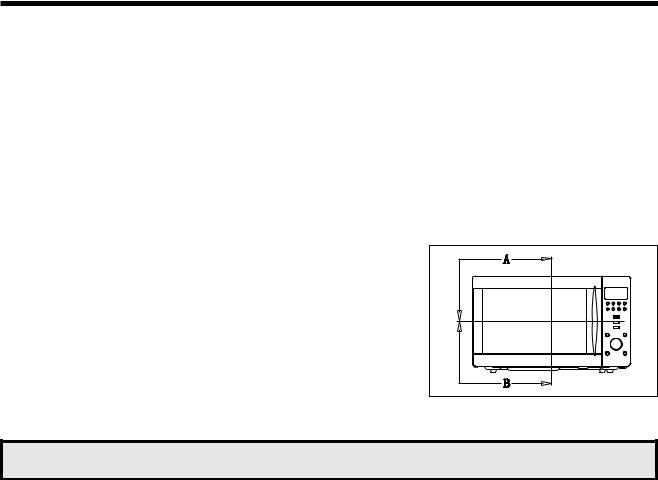
4. Method to reduce the gap between the door seal and the oven front surface.
(1) To reduce gap located on part ‘A’.
• Loosen two screws on stopper hinge top, and then push the door to contact the door seal to oven front surface.
• Tighten two screws.
(2) To reduce gap located on part ‘B’.
•Loosen two screws on stopper hinge under, and then push the door to contact the door seal to oven front surface.
•Tighten two screws.
NOTE : A small gap may be acceptable if the microwave leakage does not exceed 4mW does not exceed 4mW/cm2.
9
5. To remove: control panel parts.
B01 |
B02 |
B03 |
B04 |
B05 |
B06 |
B07 B08 B09 B10 B11 B12
REF NO. |
PART CODE |
PART NAME |
DESCRIPTION |
Q TY |
REMARK |
|
B01 |
3515501720 |
WINDOW DISPLAY |
SAN |
1 |
|
|
B02 |
3511605020 |
DECORATOR C/PANEL |
STS 304 T0.5 HL |
1 |
|
|
B03 |
3516724140 |
C-PANEL |
ABS XR-401 H-2938 |
1 |
|
|
B04 |
3516908440 |
BUTTON FUNCTION-B |
ABS SG-175 SG-0760D |
1 |
|
|
B05 |
3516908340 |
BUTTON FUNCTION-A |
ABS XR-401 H-2938 |
1 |
|
|
B06 |
3513406040 |
KNOB VOLUME |
ABS SG-175 SG-0760D |
1 |
|
|
B07 |
3511605120 |
DECORATOR RING |
ABS |
4 |
|
|
B08 |
3516908540 |
BUTTON FUNCTION-C |
ABS SG-175 SG-0760D |
4 |
|
|
B09 |
3514323130 |
SUB PCB ASS Y |
KOC-1B4K |
1 |
|
|
B10 |
7121301011 |
SCREW TAPPING |
T2S PAN 3X10 MFZN |
7 |
|
|
B11 |
PKMPMSAD00 |
MAIN PCB ASSY |
|
KOC-1B4K0S |
1 |
|
PKMPMSAD20 |
|
KOC-1B4K5S |
1 |
|
||
|
|
|
|
|||
|
|
|
|
|
|
|
B12 |
7122401211 |
SCREW TAPPING |
T2S TRS 4X12 MFZN |
4 |
|
|
(1)Remove four screws(B12) which secure the control panel.
(2)Pull out the Main PCB assembly(B11).
(3)Remove seven screws(B10) which secure the control panel.
(4)Pull out the Sub PCB assembly(B09).
(5)Pull out the Knob volume(B06) from the Sub PCB assembly.
(6)Pull out six buttons from the control panel.
(7)Pull out Decorator ring(B07) and Window display (B01) from the control panel.
(8)Pull out the Decorator c-panel (B02) from the control panel.
(9)Reverse the above steps for reassembly.
10
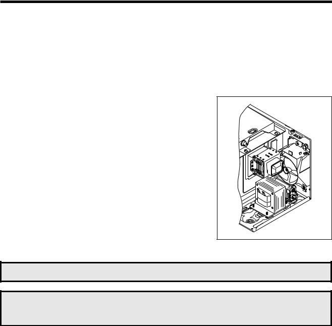
6.To remove high voltage capacitor.
(1)Remove a screw which secure the grounding ring terminal of the H.V.diode and the capacitor holder.
(2)Remove the H.V. diode from the capacitor holder.
(3) Reverse the above steps for reassembly.
High voltage circuit wiring
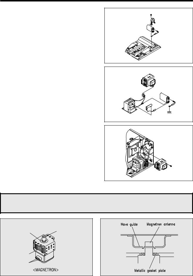
7. To remove magnetron.
(1) Remove a screw which secure the magnetron.
(2)Remove the magnetron.
(3)Reverse the above steps for reassembly.
CAUTION : Never install the magnetron without the metallic gasket plate which is packed with each magnetron to prevent microwave leakage. Whenever repair work is carried out on magnetron, check the microwave leakage. It shall not exceed 4mW/cm2 for a fully assembled oven with door normally closed.
Metallic |
Magnetron antenna |
gasket |
|
plate |
|
Cooling fin
Filament terminal
11
 Loading...