


S/M No: FRSU20IA01
Refrigerator
Caution
:In this Manual, some parts can be changed for improving, their performance without notice in the parts list. So, if you need the latest parts information,please refer to PPL(Parts Price List) in Service Information Center
July . 2005
C O N T E N T S |
|
1. WARNINGS AND PRECAUTIONS FOR SAFETY -------------------------------------------- |
2 |
2. EXTERNAN VIEW |
|
2-1. External Size ----------------------------------------------------------------------------------------- |
3 |
2-2. Name of Each Parts --------------------------------------------------------------------------------- |
6 |
3. SPECIFICATION --------------------------------------------------------------------------------------- |
11 |
4. OPERATION AND FUNCTIONS ------------------------------------------------------------------- |
14 |
5. CIRCUIT OPERATION |
|
5-1. Power Circuit Diagram ----------------------------------------------------------------------------- |
34 |
5-2. Function of Each Sensor -------------------------------------------------------------------------- |
35 |
5-3. Relay Function --------------------------------------------------------------------------------------- |
37 |
5-4. Fan Function ----------------------------------------------------------------------------------------- |
39 |
6. DIAGRAM |
|
6-1. Wiring Diagram --------------------------------------------------------------------------------------- |
40 |
6-2. Circuit Diagram of Main PCB --------------------------------------------------------------------- |
42 |
7. COMPONENT LOCATE VIEW --------------------------------------------------------------------- |
46 |
8. HOW TO CHECK EACH PARTS |
|
8-1. Hose Ice Maker Tube ------------------------------------------------------------------------------- |
48 |
8-2. Bracket Geared Motor ------------------------------------------------------------------------------ |
49 |
8-3. Dispenser Micro Switch ---------------------------------------------------------------------------- |
50 |
8-4. Dispenser Solenoid Valve ------------------------------------------------------------------------- |
51 |
8-5. Main PCB ---------------------------------------------------------------------------------------------- |
52 |
8-6. Ice Maker ---------------------------------------------------------------------------------------------- |
53 |
9. TROUBLE DIAGNOSIS |
|
9-1. Power Failure ----------------------------------------------------------------------------------------- |
56 |
9-2. Freezer Compartment ------------------------------------------------------------------------------ |
57 |
9-3. Refrigerator Compartment ------------------------------------------------------------------------- |
63 |
9-4. Operation Noise of Refrigerator ------------------------------------------------------------------ |
67 |
9-5. Door ----------------------------------------------------------------------------------------------------- |
74 |
10. COOLING CYCLE HEAVY REPAIR |
|
10-1. Summary of Heavy Repair ----------------------------------------------------------------------- |
75 |
10-2. Precaution during Heavy Repair --------------------------------------------------------------- |
76 |
10-3. Practical Work for Heavy Repair --------------------------------------------------------------- |
77 |
10-4. Standard Regulations for Heavy Repair ------------------------------------------------------ |
79 |
10-5. Brazing Reference Drawing --------------------------------------------------------------------- |
80 |
11. INSTALLATION GUIDE |
|
11-1. Installation Preparation --------------------------------------------------------------------------- |
81 |
11-2. If the Refrigerator can not enter the Door ---------------------------------------------------- |
82 |
11-3. Refrigerator Leveling & Door Adjustment ---------------------------------------------------- |
84 |
11-4. Water Line Installation ---------------------------------------------------------------------------- |
85 |
11-5. Dispenser Water Flow ---------------------------------------------------------------------------- |
87 |
12. EXPLODED VIEW & PARTS LIST |
|
12-1. FRS(N)-U20IA -------------------------------------------------------------------------------------- |
88 |
12-2. FRS(N)-U20DA ------------------------------------------------------------------------------------- |
98 |
12-3. FRS(N)-U20EA ------------------------------------------------------------------------------------- |
109 |
12-4. FRS(N)-U20FA ------------------------------------------------------------------------------------- |
120 |
12-4. FRS(N)-U20GA ------------------------------------------------------------------------------------- |
131 |
1

1. WARNINGS AND PRECAUTIONS FOR SAFETY
Please observe the following safety precautions in order to use safely and correctly the refrigerator and to prevent accident and danger during repair.
1. Be care of an electric shock. Disconnect power cord from wall outlet and wait for more than three minutes before replacing PCB parts.
Shut off the power whenever replacing and repairing electric components.
2.When connecting power cord, please wait for more than five minutes after power cord was disconnected from the wall outlet.
3.Please check if the power plug is pressed down by the refrigerator against the wall. If the power plug was damaged, it may cause fire or electric shock.
4.If the wall outlet is over loaded, it may cause fire.
Please use its own individual electrical outlet for the refrigerator.
5.Please make sure the outlet is properly earthed, particularly in wet or damp area.
6.Use standard electrical components when replacing them.
7.Make sure the hook is correctly engaged.
Remove dust and foreign materials from the housing and connecting parts.
8.Do not fray, damage, machine, heavily bend, pull out or twist the power cord.
9.Please check the evidence of moisture intrusion in the electrical components. Replace the parts or mask it with insulation tapes if moisture intrusion was confirmed.
10.Do not touch the icemaker with hands or tools to confirm the operation of geared motor.
11.Do not let the customers repair, disassemble and reconstruct the refrigerator for themselves. It may cause accident, electric shock, or fire.
12.Do not store flammable materials such as ether, benzene, alcohol, chemicals, gas, or medicine in the refrigerator.
13.Do not put flower vase, cup, cosmetics, chemicals, etc., or container with full of water on the top of the refrigerator.
14.Do not put glass bottles with full of water into the freezer.
The contents shall freeze and break the glass bottles.
15.When you scrap the refrigerator, please disconnect the door gasket first and scrap it where children are not accessible.
2

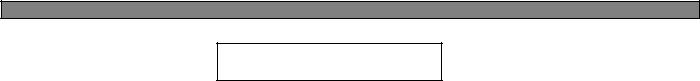
2. EXTERNAL VIEWS
2-1. External Size |
■ FRS(N)-U20IA |
3 |
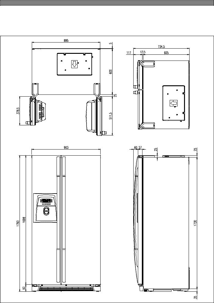
■ FRS(N)-U20DA / FRS(N)-U20EA |
4 |
■ FRS(N)-U20FA / FRS(N)-U20GA |
5 |
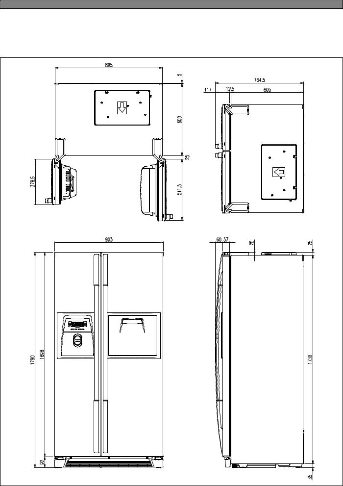
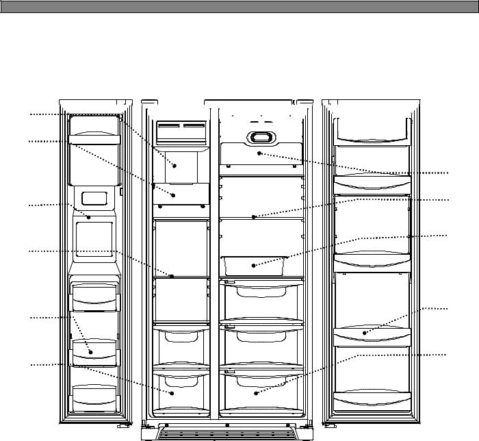
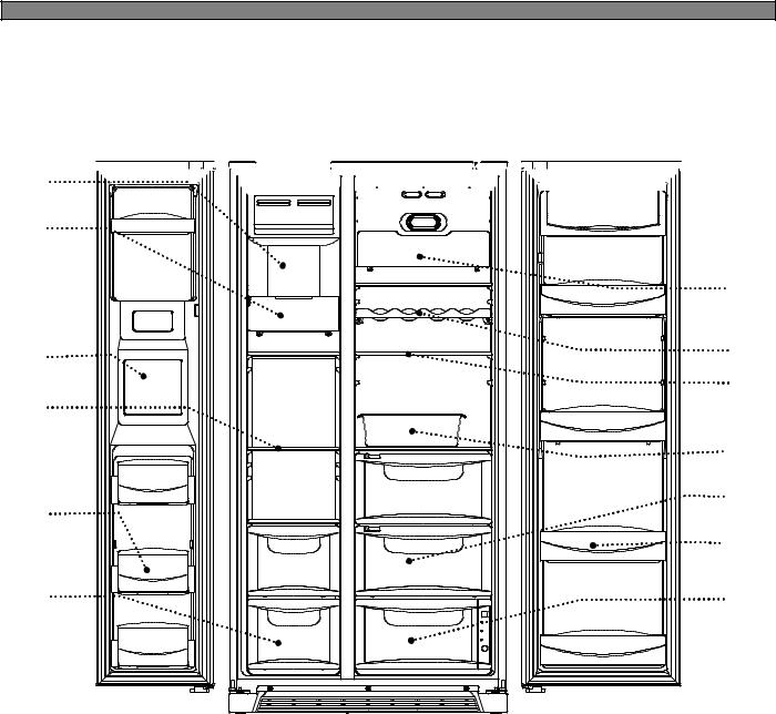
2-2. Name of Each Parts
■ FRS(N)-U20IA
1


 6
6
2 


|
7 |
3 |
8 |
4 |
9 |
|
|
|
10 |
5


 11
11
12
|
Freezer Compartment |
|
|
Refrigerator Compartment |
|
|
|
|
|
1. |
Freezer light |
6. |
Dairy pocket |
|
|
|
|
|
|
2. |
Freezer pocket |
7. |
Refrigerator light |
|
|
|
|
|
|
3. |
Ice tray |
8. |
Chilled case |
|
|
|
|
|
|
4. |
Freezer shelf |
9. |
Refrigerator shelf |
|
|
|
|
|
|
5. |
Freezer case |
10. |
Movable Egg case |
|
|
|
|
|
|
|
|
11. |
Refrigerator pocket |
|
|
|
|
|
|
|
|
12. |
Refrigerator case |
|
|
|
|
|
|
6
■ FRS(N)-U20DA
1


 7
7
2 |
|
|
8 |
3 |
9 |
|
|
|
10 |
4 |
|
5 |
11 |
|
|
6 |
12 |
|
|
Freezer Compartment |
|
|
Refrigerator Compartment |
|
|
|
|
|
1. |
Ice cubes storage case |
7. |
Dairy pocket |
|
|
|
|
|
|
2. |
Freezer light |
8. |
Refrigerator light |
|
|
|
|
||
3. Water/Ice dispenser |
9. |
Refrigerator shelf |
||
|
|
|
|
|
4. |
Freezer shelf |
10. |
Movable egg case |
|
|
|
|
|
|
5. |
Freezer pocket |
11. |
Refrigerator pocket |
|
|
|
|
|
|
6. |
Freezer case |
12. |
Refrigerator case |
|
|
|
|
|
|
7
■ FRS(N)-U20EA
1


 7
7
2 |
|
|
8 |
3 |
9 |
|
|
|
10 |
4 |
|
|
11 |
5 |
12 |
|
|
|
13 |
6 |
14 |
|
Freezer Compartment |
|
|
Refrigerator Compartment |
|
|
|
|
|
1. |
Ice cubes storage case |
7. |
Dairy pocket |
|
|
|
|
|
|
2. |
Freezer light |
8. |
Refrigerator light |
|
|
|
|
||
3. Water/Ice dispenser |
9. |
Shelf wine (option) |
||
|
|
|
|
|
4. |
Freezer shelf |
10. |
Refrigerator shelf |
|
|
|
|
|
|
5. |
Freezer pocket |
11. |
Movable egg case |
|
|
|
|
|
|
6. |
Freezer case |
12. |
Refrigerator case |
|
|
|
|
|
|
|
|
13. |
Refrigerator pocket |
|
|
|
|
|
|
|
|
14. |
Magic cool zone |
|
|
|
|
|
|
8

■ FRS(N)-U20FA |
1 |
2 |
3 |
4 |
5 |
6 |
7 |
8 |
9 |
10 |
11 |
12 |
13 |
|
Freezer Compartment |
|
|
Refrigerator Compartment |
|
|
|
|
|
1. |
Ice cubes storage case |
7. |
Dairy pocket |
|
|
|
|
|
|
2. |
Freezer light |
8. |
Refrigerator light |
|
|
|
|
||
3. Water/Ice dispenser |
9. |
Refrigerator shelf |
||
|
|
|
|
|
4. |
Freezer shelf |
10. |
Homebar pocket |
|
|
|
|
|
|
5. |
Freezer pocket |
11. |
Movable egg case |
|
|
|
|
|
|
6. |
Freezer case |
12. |
Refrigerator pocket |
|
|
|
|
|
|
|
|
13. |
Refrigerator case |
|
|
|
|
|
|
9

■ FRS(N)-U20GA |
|
1 |
7 |
2 |
8 |
|
|
|
9 |
3 |
|
|
10 |
4 |
11 |
|
12 |
|
13 |
5 |
|
|
14 |
6 |
15 |
|
Freezer Compartment |
|
|
Refrigerator Compartment |
|
|
|
|
|
1. |
Ice cubes storage case |
7. |
Dairy pocket |
|
|
|
|
|
|
2. |
Freezer light |
8. |
Refrigerator light |
|
|
|
|
||
3. Water/Ice dispenser |
9. |
Shelf wine (option) |
||
|
|
|
|
|
4. |
Freezer shelf |
10. |
Refrigerator shelf |
|
|
|
|
|
|
5. |
Freezer pocket |
11. |
Homebar pocket |
|
|
|
|
|
|
6. |
Freezer case |
12. |
Movable egg case |
|
|
|
|
|
|
|
|
13. |
Refrigerator pocket |
|
|
|
|
|
|
|
|
14. |
Refrigerator case |
|
|
|
|
|
|
|
|
15. |
Magic cool zone |
|
|
|
|
|
|
10

3. SPECIFICATION
3-1. Specification
|
|
|
Item |
|
|
|
|
|
|
|
|
Specification |
|
|
|
|
|
|||
|
|
|
|
|
|
|
|
|
|
|
|
|
|
|
|
|
|
|||
|
|
Model Name |
FRS(N)- |
|
FRS(N)- |
|
FRS(N)- |
FRS(N)- |
|
FRS(N)- |
||||||||||
|
|
U20IA |
|
U20DA |
|
U20EA |
|
|
U20FA |
|
U20GA |
|||||||||
|
|
|
|
|
|
|
|
|
|
|||||||||||
ISO Gross |
|
|
Total |
570 Li |
|
|
541 Li |
|
|
525 Li |
|
|
541Li |
|
536 Li |
|||||
|
|
|
|
|
|
|
|
|
|
|
|
|
|
|
|
|
|
|
||
|
|
|
|
|
|
|
|
|
|
|
|
|
|
|
|
|
|
|
||
Volume |
|
|
Freezer |
209 Li |
|
|
184 Li |
|
|
178 Li |
|
|
184 Li |
|
184 Li |
|||||
|
(Li) |
|
|
|
|
|
|
|
|
|
|
|
|
|
|
|
|
|
|
|
|
|
Refrigerator |
361 Li |
|
|
357 Li |
|
|
337 Li |
|
|
357 Li |
|
352 Li |
||||||
|
|
|
|
|
|
|
|
|
|
|
||||||||||
|
|
|
|
|
|
|
|
|
|
|
|
|
|
|
|
|
|
|
|
|
ISO Storage |
|
|
Total |
537 Li |
|
|
504 Li |
|
|
504 Li |
|
|
504 Li |
|
500 Li |
|||||
|
|
|
|
|
|
|
|
|
|
|
|
|
|
|
|
|
|
|
||
|
|
|
|
|
|
|
|
|
|
|
|
|
|
|
|
|
|
|
||
Volume |
|
|
Freezer |
198 Li |
|
|
170 Li |
|
|
170 Li |
|
|
170 Li |
|
170 Li |
|||||
|
(Li) |
|
|
|
|
|
|
|
|
|
|
|
|
|
|
|
|
|
|
|
|
|
Refrigerator |
339 Li |
|
|
334 Li |
|
|
334 Li |
|
|
334 Li |
|
330 Li |
||||||
|
|
|
|
|
|
|
|
|
|
|
||||||||||
|
|
|
|
|
|
|
|
|
|
|
|
|
|
|
|
|
|
|
|
|
|
|
|
Weight |
104kg |
|
|
113kg |
|
|
115kg |
|
|
115kg |
|
117kg |
|||||
|
|
|
|
|
|
|
|
|
|
|
|
|
|
|
|
|
|
|
|
|
|
External Dimension |
|
|
|
|
903 mm x 734.5mm x 1790 mm |
|
|
||||||||||||
|
(Width x Depth x Height) |
|
|
|
|
|
|
|||||||||||||
|
|
|
|
|
|
|
|
|
|
|
|
|
|
|
|
|
||||
C |
|
|
Evaporator |
|
|
|
|
|
|
|
|
Fin Type |
|
|
|
|
|
|||
|
|
|
|
|
|
|
|
|
|
|
|
|
|
|
|
|
|
|
|
|
|
|
Condenser |
|
|
|
|
|
|
|
Fan Cooling System |
|
|
||||||||
Y |
|
|
|
|
|
|
|
|
|
|
|
|||||||||
C |
|
|
|
|
|
|
|
|
|
|
|
|
|
|
|
|
|
|
|
|
|
|
|
|
|
|
|
|
|
|
|
|
|
|
|
|
|
|
|
|
|
L |
|
|
|
Dryer |
|
|
|
|
|
|
|
Molecular Sieve XH-9 |
|
|
||||||
E |
|
|
|
|
|
|
|
|
|
|
|
|
|
|
|
|
|
|
|
|
|
Capillary Tube |
|
|
|
|
|
|
IDΦ0.7 × T0.55 × L2200 |
|
|
||||||||||
|
|
|
|
|
|
|
|
|
|
|||||||||||
|
|
|
|
|
|
|
|
|
|
|
|
|
|
|
|
|
|
|||
|
|
|
|
|
|
|
|
|
|
|
|
|
|
|
|
|||||
|
|
|
|
Description |
HPL30YG-5 |
|
|
|
|
|
MK183Q-L2U |
|
MK4A5Q-R1U |
|||||||
|
|
|
|
|
|
|
|
|
|
|
|
|
|
|||||||
Compressor |
|
|
Part Code |
395S130R50 |
|
|
|
3956183D50 |
|
3956145250 |
||||||||||
|
|
|
|
|
|
|
|
|
|
|
|
|
|
|||||||
|
|
|
|
Refrigerant ( g ) |
R-134a (190g) |
|
|
R-134a (190g) |
|
R-600a (76g) |
||||||||||
|
|
|
|
|
|
|
|
|
|
|
|
|
|
|
|
|
||||
SWITCH |
|
|
Description |
308NHB, S330 |
|
|
|
|
|
265RHB, S330 |
|
|
||||||||
|
|
|
|
|
|
|
|
|
|
|
|
|
|
|
|
|
|
|
||
P RELAY AS |
|
|
Part Code |
3018129810 |
|
|
|
|
|
|
3011402100 |
|
|
|
||||||
|
|
|
|
|
|
|
|
|
|
|
|
|
||||||||
|
|
|
|
|
|
|
|
|
|
|
|
|
|
|
|
|
|
|
||
|
|
|
|
|
|
|
|
|
|
|
|
|
|
|
|
|
|
|||
|
|
|
|
Description |
CP-2PIN |
|
|
|
|
BS-1363 |
|
KP-550 |
|
|
CP-2PIN |
|||||
|
|
|
|
(EUROPE) |
|
|
|
|
(AUSTRALIA) |
|
(Other Country) |
|||||||||
CORD POWER AS |
|
|
|
|
|
|
|
|
|
|||||||||||
Part Code |
3011346700 |
|
3011347300 |
|
3011301080 |
|
3011347400 |
|||||||||||||
|
|
|
|
|
|
|
||||||||||||||
|
|
|
|
|
|
|
|
|
|
|
|
|
|
|
|
|
|
|
|
|
11
|
|
|
|
|
|
|
|
|
|
|
|
|
|
|
|
|
|
|
|
|
|
|
|
|
|
|
Item |
|
|
Specification |
|
|
|
||
|
|
|
|
|
|
|
|
|
|
|
|
|
|
|
Model Name |
FRS(N)- |
FRS(N)- |
|
FRS(N)- |
|
FRS(N)- |
FRS(N)- |
|
|
|
|
U20IA |
U20DA |
|
U20EA |
|
U20FA |
U20GA |
|
|
|
|
|
|
|
|
|
|||||
|
|
|
|
|
|
|
|
|
|
|
|
|
|
S |
D-Sensor |
|
|
|
PBN-43 |
|
|
|
|
|
|
E |
|
|
|
|
|
|
|
|
|
|
|
|
|
|
|
|
|
|
|
|
|
|
|
N |
F-Sensor |
|
|
|
PBN-38 |
|
|
|
|
|
|
S |
|
|
|
|
|
|
|||
|
|
|
|
|
|
|
|
|
|
|
|
|
|
O |
|
|
|
|
|
|
|
|
|
|
|
|
|
|
|
|
|
|
|
|
|
|
|
R |
R-Sensor |
|
|
|
PBN-43 |
|
|
|
|
|
|
|
|
|
|
|
|
|
|
||
|
|
|
Defrost Heater |
|
|
AC220V / 192W |
|
|
|
||
|
|
|
|
|
|
|
|
|
|
|
|
|
|
|
Main Duct Heater |
|
|
|
AC220V / 7W |
|
|
|
|
|
|
H |
|
|
|
|
|
|
|
|
|
|
|
|
|
|
|
|
|
|
|
|
|
|
|
E |
Louver Heater |
|
|
|
AC220V / 8W |
|
|
|
|
|
|
A |
|
|
|
|
|
|
|||
|
|
|
|
|
|
|
|
|
|
|
|
|
|
T |
Dispenser Heater |
- |
|
|
AC220V / 5W |
|
|
||
|
|
E |
|
|
|
|
|||||
|
|
|
|
|
|
|
|
|
|
|
|
|
|
R |
|
|
|
|
|
|
|
|
|
|
|
Water Pipe Heater |
- |
|
|
AC220V / 5W |
|
|
|||
|
|
|
|
|
|
|
|||||
|
|
|
|
|
|
|
|
||||
|
|
|
|
|
|
|
|
|
|
|
|
|
|
|
Homebar Heater |
|
- |
|
|
|
AC220V / 10W |
|
|
|
|
|
|
|
|
|
|
|
|
|
|
|
|
|
Main Fuse (Power cord) |
|
|
|
AC250V 12A |
|
|
|
|
|
|
|
|
|
|
|
|
||||
|
|
|
Fuse Temp (Defrost) |
|
AC250V , 10A , 77 |
|
|
||||
|
E |
|
|
|
|
|
|
|
|
|
|
|
|
F-Fan Motor |
|
DC13V / 2050±100 rpm |
|
|
|||||
|
L |
|
|
|
|
||||||
|
|
|
|
|
|
|
|
|
|
|
|
|
E |
P |
|
|
|
|
|
|
|
|
|
|
|
|
|
|
|
|
|
|
|
||
|
C |
R-Fan Motor |
|
DC13V / 1850±100 rpm |
|
|
|||||
|
A |
|
|
|
|||||||
|
T |
|
|
|
|
|
|
|
|
|
|
|
R |
|
|
|
|
|
|
|
|
|
|
|
R |
|
|
|
|
|
|
|
|
|
|
|
T |
Condenser Fan Motor |
|
DC13V / 1100±100 rpm |
|
|
|||||
|
I |
|
|
|
|||||||
|
S |
|
|
|
|
|
|
|
|
|
|
|
C |
|
|
|
|
|
|
|
|
|
|
|
|
|
|
|
|
|
|
|
|
|
|
|
A |
|
F-Lamp |
|
AC230~240V / 25W (2EA) |
|
|
||||
|
L |
|
|
|
|
||||||
|
|
|
|
|
|
|
|
|
|
|
|
|
|
|
R-Lamp |
|
AC230~240V / 25W (2EA) |
|
|
||||
|
|
|
|
|
|
|
|
||||
|
|
|
Door Switch , F / R |
|
SP201R-7DL / SP201R-7DR |
|
|
||||
|
|
|
|
(SPF101B-2D / SPF101B-1D) |
|
|
|||||
|
|
|
|
|
|
|
|||||
|
|
|
|
|
|
|
|
|
|
|
|
( ) is the specification for the model which use R-600a(refrigerant)
Refrigerant |
|
|
Model Name |
|
|
|
|
|
|
|
|
R-134a |
FRS-U20IA |
FRS-U20DA |
FRS-U20EA |
FRS-U20FA |
FRS-U20GA |
|
|
|
|
|
|
R-600a |
FRN-U20IA |
FRN-U20DA |
FRN-U20EA |
FRN-U20FA |
FRN-U20GA |
|
|
|
|
|
|
12

4. OPERATION AND FUNCTIONS
4-1. Display
4-1-1. FRS(N)-U20IA
INPUT |
CONTROL OBJECT |
|||
|
|
|
|
|
FRZ.TEMP, REF.TEMP |
Inner Control (Lamp-LED) |
|||
|
|
|
|
|
CONTENTS |
|
|
REMARKS |
|
|
|
|
|
|
|
|
|
|
|
|
|
Temperature adjustment button |
|
|
|
|
for freezer compartment. |
|
|
|
|
|
|
|
|
|
Temperature adjustment button |
|
|
|
|
for refrigerator compartment. |
|
|
1.“FRZ.TEMP” Button
1)Temperature control of Freezer compartment
2)5 step mode of successive temperature mode.
3)Initial mode by power input : “3”
Whenever pressing button, setting is repeated in the order of Medium(3) → Medium Max(4) → Max(5) → Min(1) → Medium Min(2).
Temperature Chang |
Min |
Medium |
Mid |
Medium |
Max |
|
Min |
Max |
|||||
|
|
|
|
|||
Temp indication |
1 |
2 |
3 |
4 |
5 |
|
|
|
|
|
|
|
2.“REF.TEMP” button.
1)Temperature control of Refrigerator compartment
2)5 step mode of successive temperature mode.
3)Initial mode by power input : “3”
Whenever pressing button, setting is repeated in the order of Medium(3) → Medium Max(4) → Max(5) → Min(1) → Medium Min(2).
Temperature Change |
Min |
Medium |
Mid |
Medium |
Max |
|
Min |
Max |
|||||
|
|
|
|
|||
Temp indication |
1 |
2 |
3 |
4 |
5 |
|
|
|
|
|
|
|
The actual inner temperature varies depending on the food status, as the indicated setting temperature is a target temperature, not actual temperature within refrigerator.
Refrigeration function is weak in the initial time.
Please adjust temperature as above after using refrigerator for minimum2~3 days.
13
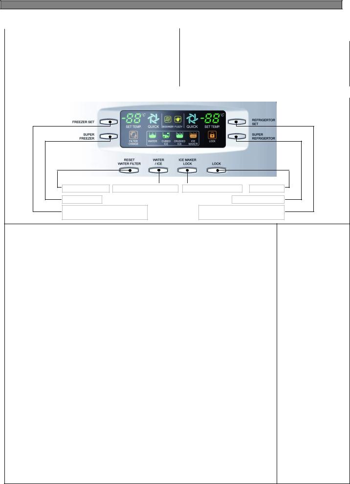
4-1-2. FRS(N)-U20DA / EA / FA / GA
INPUT |
CONTROL OBJECT |
|
|
Front PCB button
FREEZER SET, REFRIGERATOR SET
SUPER FREEZER, SUPER REFRIGERATOR FCP C-LED RESET FILTER, WATER / ICE, ICE MAKER LOCK
,LOCK
CONTENTS |
REMARKS |
|
|
Water filter reset |
Dispenser select button |
Super freezer |
|
Temperature adjustment button |
|
for freezer compartment. |
|
Ice maker lock button |
Lock button |
Super Refrigerator |
|
Temperature adjustment button |
|
for refrigerator compartment. |
|
1. Display control
FCP-LED |
Control |
|
|
|
|
88 DISPLAY (SET TEMP.) |
Initial mode : Freezer & Refrigerator set→ |
|
Medium (-19 /4 ) |
||
|
||
|
|
|
SUPER FREEZER,SUPER |
Dial |
|
REFRIGERATOR ICON |
||
|
||
|
|
|
FUZZY, DEODORIZER ICON |
Always ON |
|
|
|
|
WATER / CUBED ICE/ CRUSHED ICE ICON |
Dial |
|
|
|
|
LOCK ICON |
Dial |
|
|
|
|
ICE MAKER LOCK ICON |
Dial |
|
|
|
|
FILTER CHANGE ICON |
After six month, LED ON |
|
|
|
2.“FREEZER SET” Button
1)Temperature control of freezer compartment
2)7 step mode of successive temperature mode.
3)Initial mode by power input : “Medium(-19 )”
Whenever pressing button, setting is repeated in the order of
Medium (-19 ) → Medium Max 1 (-20 ) → Medium Max 2 (-21 ) → Max (-22 ) → Min (-16 ) → Medium Min 2 (-17 ) → Medium Min 2 (-18 ).
Letters are indicated on 88 Display LED
Temperature |
Min |
Medium |
Medium |
Medium |
Medium |
Medium |
Max |
|
Change |
Min 1 |
Min 2 |
Max 1 |
Max 2 |
||||
|
|
|
||||||
Temp |
-16 |
-17 |
-18 |
-19 |
-20 |
-21 |
-22 |
|
indication |
||||||||
|
|
|
|
|
|
|
||
|
|
|
|
|
|
|
|
3.“SUPER FREEZER” Button
When this mode is chosen, the icon (FREEZER QUICK) is ON.
14

CONTENTS
4.“REFRIGERATOR SET” button.
1)Temperature control of Refrigerator compartment
2)5 step mode of successive temperature mode.
3)Initial mode by power input : “Medium (4 )”
Whenever pressing button, setting is repeated in the order of
Medium (4 ) → Medium Max (3 ) → Max (2 ) → Min (6 ) → Medium Min (5 ).
Letters are indicated on 88 Display LED
Temperature Change |
Min |
Medium |
Mid |
Medium |
Max |
|
Min |
Max |
|||||
|
|
|
|
|||
Temp indication |
6 |
5 |
4 |
3 |
2 |
|
|
|
|
|
|
|
5. “SUPER REFRIGERATOR” button.
When this mode is chosen, the icon (REFRIGERATOR QUICK) is ON.
6.“WATER / ICE” button
1)Select Water / Cubed Ice / Crushed Ice.
2)Icon lights up to show your selection is on. Initial mode by power input : “Water” mode.
3)The mode of Cubed Ice or Crushed Ice continues for 1 hour and then changes to Water. (Water icon turns ON)
7.“ICE MAKER LOCK” button
1)Start by pushing “ICE MAKER LOCK” button
“ICE MAKER LOCK” icon is on
“WATER” icon is always on
2)Stop by pushing “ICE MAKER LOCK” button again
“ICE MAKER LOCK” icon is off
“WATER” icon is on
8.“RESET WATER FILTER” button
1)The normal (ICON OFF) is on for 6 month after are first power input.
2)After sic months, icon is ON.
3)How to reset Filter information
Push the “RESET WATER FILTER” button for 3 seconds after change.
9.“LOCK” button
1)This button stops operation of different button.
“LOCK” icon is on
Press this button to lock out this case and to keep temperature and function setting.
2)Push “LOCK” button again for more than a second to stop it.
The actual inner temperature varies depending on the food status, as the indicated setting temperature is a target temperature, not actual temperature within refrigerator.
Refrigeration function is weak in the initial time.
Please adjust temperature as above after using refrigerator for minimum2~3 days.
REMARKS
REFERENCE : Please wait for 2-3 seconds in order
to take final ice or drops of water when taking out cup from the pressing switches after taking ice or water.
15
4-2. Defrost Mode
INPUT |
CONTROL OBJECT |
|
|
1. Comp
1. Defrosting Cycle 2. F-Fan
3. R-Fan
4. D-Heater
CONTENTS |
REMARKS |
|
|
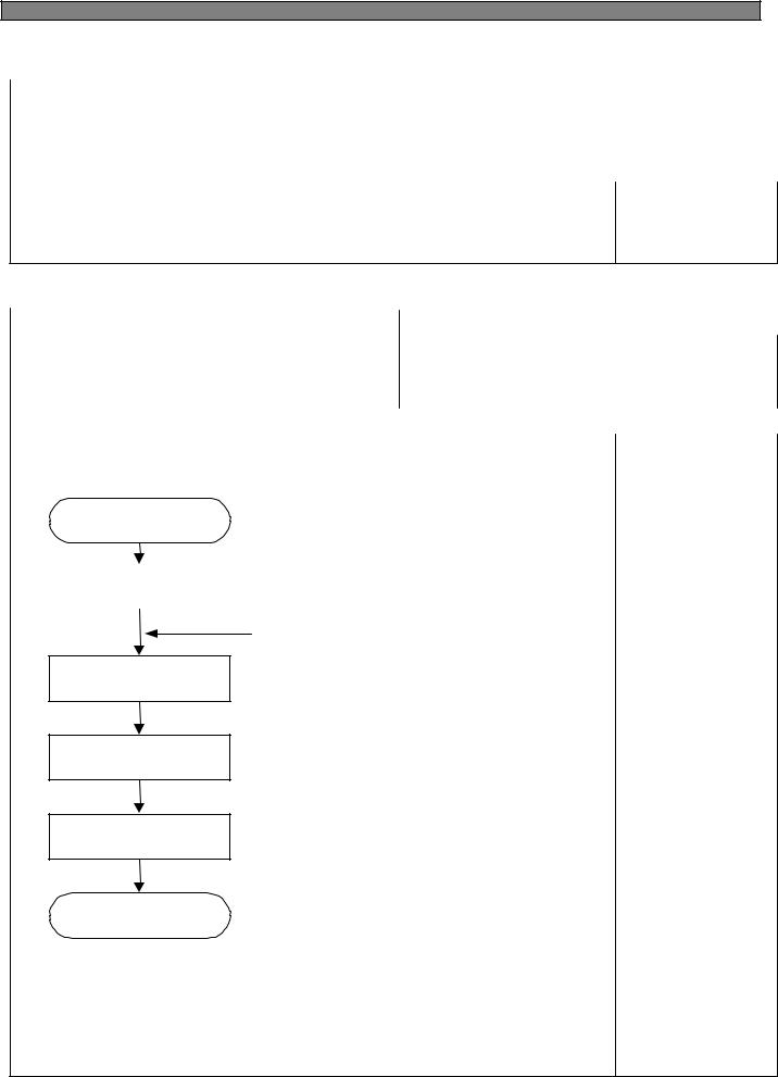
1. Defrost Mode
Pre-Cool
Heater
Defrosting
Pause
Fan-Delay
Pre-Cool
1)Time : 50 minutes
2)Comp , F-fan : ON R-fan : Control
D-HTR : OFF
3) If F-sensor ≤ -27 , then Pre-Cool becomes. OFF
Heater
Defrosting
1)Comp, F-fan, R-fan : OFF D-HTR : ON
2)Time limit
30 seconds : Heater is ON regardless of D-sensor temperature right after defrosting start
30 minutes : in case of D1Error
80 minutes : in normal control state
3)If D-sensor ≥13 , Heater Defrosting is OFF
Pause
Time : 7 minutes
Comp, F-fan, R-fan, Heater etc. : OFF
Fan-Delay
1) Time : 5 minutes
Comp : ON and F-fan, R-fan, Heater : OFF
2.The defrost mode start with the following conditions
1)Total operation time of comp. becomes : 6,8,10,……… 24 hours.
Comp. operating rate : more 85%
Total door open time : 2 minutes
(Any door, F or R open time is over 2 minutes.)
Any error mode : R1, F1, D1, F3, RT/S, Door-switch etc.)
2)Defrosting mode starts unconditionally as long as total comp. work time is 24 hours, even if the above conditions 1) are not satisfied.
3)Defrosting mode starts immediately as long as total time of [comp. ON + comp. OFF] is over 60 hours, even if the above 1) and 2) conditions are not satisfied.
3.In providing initial power (or returning power failure)
If D-sensor temp. ≤ 3.5 , defrosting mode starts .
16

|
CONTENTS |
REMARKS |
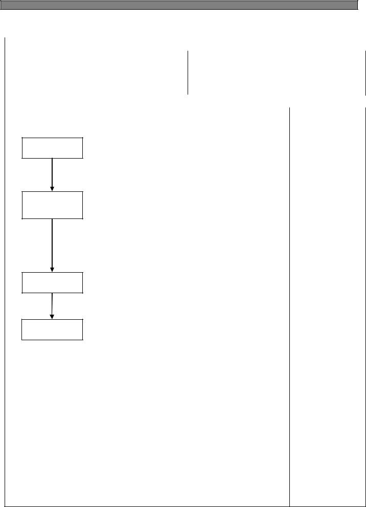
4. Flow Chart of Defrosting Start |
|
|
|
Start |
|
|
Comp. operating time |
NO |
|
is over 2 hours? |
|
|
YES |
|
YES |
Total time is |
|
|
|
|
|
over 60 hours? |
|
|
NO |
|
YES |
Comp. operating time |
|
|
is over 24 hours? |
|
|
NO |
|
|
Comp. operating time |
NO |
|
|
|
|
is over 6 hours? |
|
|
YES |
|
YES |
Comp. operating rate |
|
|
|
|
|
is more 85%? |
|
|
NO |
|
YES |
Any error ? |
|
|
|
|
|
NO |
|
YES |
Total door open |
|
|
time is over 2 min? |
|
|
NO |
|
Defrosting start |
End |
|
|
17 |
|
4-3. c (Forced Defrosting) Mode
INPUT |
CONTROL OBJECT |
|
|
1. Comp
1. Defrosting Cycle 2. F-Fan
3. R-Fan
4. D-Heater
CONTENTS |
REMARKS |
|
|
1. A/S Defrosting Mode (Heater defrost → Pause → Fan Delay)
Heater
Defrosting
Pause
Fan-Delay
Heater
Defrosting
1)Comp, F-fan, R-fan : OFF D-HTR : ON
2)Time limit
30 seconds : Heater is ON regardless of D-sensor temperature right after defrosting start
30 minutes : in case of D1-Error
80 minutes : in normal control state
3) If D-sensor ≥13 , Heater Defrosting is OFF
Pause
Time : 7 minutes
Comp, F-fan, R-fan, Heater etc. : OFF
Fan-Delay
1) Time : 5 minutes Comp : ON
F-fan, R-fan, Heater : OFF
2.How to start
1)Push “REF.TEMP” button 5 times while pushing “FRZ.TEMP” button simultaneously.
--------- FRS-U20IA
2)In “LOCK” mode, push “REFRIGERATOR SET” button 5 times while pushing “FREEZER SET” button simultaneously. ------ FRS(N)-U20DA
3.How to proceed
1)Delete Pre-cool mode. (Others are same as normal defrosting)
2)Heater is ON regardless of D-sensor temp. at first 30 seconds.
(Check of defrosting current)
4-4. Fan Voltage of Control Mode
|
|
|
INPUT |
|
|
|
CONTROL OBJECT |
||
|
|
|
|
|
|
|
|
|
|
1. |
F-Sensor |
|
|
|
1. F-FAN, R-FAN, C-FAN |
||||
2. |
R-Sensor |
|
|
|
|||||
|
|
|
|
|
|
||||
|
|
|
|
|
|
|
|
|
|
|
|
|
|
CONTENTS |
|
|
|
REMARKS |
|
|
|
|
|
|
|
|
|
|
|
1. Fan voltage of control mode |
|
|
|
|
|
|
|||
|
|
|
|
|
|
|
|
|
|
|
FAN |
|
F-FAN |
|
R-FAN |
|
C-FAN |
|
|
|
|
|
|
|
|
|
|
|
|
|
Voltage |
|
13 V |
|
13 V |
|
13 V |
|
|
|
|
|
|
|
|
|
|
|
|
Refer to the 5-4. (Fan Function ) |
|
|
|
|
|
|
|||
|
|
|
|
|
|
|
|
|
|
18

4-5. Louver Heater Control
INPUT |
CONTROL OBJECT |
||
|
|
|
|
1. Comp |
Louver Heater |
||
|
|
|
|
CONTENTS |
|
REMARKS |
|
|
|
|
|
It is linked with comp.
4-6. Buzzer or Alarm Control
INPUT |
CONTROL OBJECT |
|
|
1. Control (Inner or F-PCB) buttons
2. Door Switch Buzzer
3. Initial Power Input
CONTENTS |
REMARKS |
|
|
1.Buzzer sounds if any button of Inner Control is pushed.
2.Buzzer sounds 4 times 3 seconds after initial power input.
3.Buzzer sounds for 3 or 1 times in case of A/S forced defrosting and short (pull down) operation or explanation mode.
4.If door is open, buzzer sounds after every 1 minutes for 5 minutes (Door open alarm)
4-7. Control of Interior Lights (FRS(N)-U20DA / EA / FA / GA)
|
INPUT |
|
CONTROL OBJECT |
|
|
|
|||
|
|
|
|
|
1. |
Refrigerator door switch |
|
Lamp |
|
2. |
Freezer door switch |
|
||
|
|
|
||
3. |
Home bar door switch |
|
|
|
4. |
Dispenser switch |
|
|
|
|
|
|
|
|
|
CONTENTS |
|
REMARKS |
|
|
|
|
|
|
1. Control |
refrigerator compartment lights |
|
|
|
R-Lights turn ON/OFF by R-door switch ON/OFF |
|
|
||
( For 10 minutes after sensing door open, the lights turn off automatically |
|
|
||
through door close is not sensed.) |
|
|
||
2. Control of freezer compartment lights. |
|
|
||
F-Light turn ON/OFF by F-door switch ON/OFF |
|
|
||
( For 10 minutes after sensing door open, the lights turn off automatically |
|
|
||
through door close is not sensed.) |
|
|
||
3.R-lights ON/OFF by home bar door switch ON/OFF. ( for only model with home bar ) R-lights turn ON for 10 minutes after sensing home bar door switch open.
4.Dispenser lamp control ( for only model with water/ice dispenser )
Dispenser lamp turns ON/OFF by Dispenser switch.
Dispenser lamp turns ON for 4 seconds after sensing switch close.
19
4-8. Demonstration
4-8-1. FRS(N)-U20IA
INPUT |
CONTROL OBJECT |
||
|
|
|
|
1. FRZ. TEMP |
Comp |
||
F/R-Fan |
|||
2. Door Switch |
|||
Heater |
|||
|
|||
|
|
|
|
CONTENTS |
|
REMARKS |
|
|
|
|
|
1. Start
Open and close “Freezer door switch” 5 times while pushing “FRZ. TEMP” button simultaneously.
2.Control
1)All other electrical components are OFF except for F-fan / R-fan
2)Fan Control
Door open → Fan ON / Door close → Fan OFF. 3) Display control
“FRZ. LED” and “REF. LED” are ON in good order
3.Stop
1)During Demo mode, push “Freezer door switch” open and close 5 times while pushing “FRZ. TEMP” button simultaneously.
2)Power in again
4-8-2. FRS(N)-U20DA / EA / FA / GA
INPUT |
CONTROL OBJECT |
|
|
Comp 1. “FREEZER SET, WATER/ICE” Button , Door switch F/R-Fan
Heater
CONTENTS |
REMARKS |
|
|
1. Start
Push “ICE/WATER” button 5 times while pushing “FREEZER SET” button simultaneously.
2.Control
1)All other electrical components are OFF except for F-fan / R-fan
2)Fan Control
Door OPEN → Fan ON / Door close → Fan OFF.
3.Stop or termination
1)During Demo mode, push “ICE/WATER” button 5 times while pushing “FREEZER SET” button simultaneously.
2)Power in again
20
4-9. Compensation of R-sensor ON/OFF Point
INPUT |
CONTROL OBJECT |
||
|
|
|
|
Main PCB |
Resistance of R-sensor Mid ON/OFF Point |
||
|
|
|
|
CONTENTS |
|
REMARKS |
|
|
|
|
|
Compensation of R-sensor ON/OFF temp. (down)
In case temperature of refrigerator compartment is weak or insufficient, take the following action.
FRS(N)-U20IA |
|
FRS(N)-U20DA/EA/FA/GA |
|||
|
R-SENSOR |
|
|
R-SENSOR |
|
R36 |
|
|
R36 |
|
|
R37 |
|
|
R37 |
|
|
R38 |
J2 |
J1 |
R38 |
J19 |
J18 |
|
|
||||
|
|
J1 |
|
|
J18,19 |
|
|
J2 |
|
|
|
R36 : R-SENSOR standard resistance in normal mode (31.4K)
R37 : In case of weak ref., cut J1 (or J18) to down the standard resistance by 1.5deg(2K) R38 : In case of weak ref., cut J2 (or J19) to down the standard resistance by 1.5deg(2K)
|
J1 |
- |
cut |
cut |
FRS(N) |
J2 |
- |
- |
cut |
-U20IA |
Temperature |
0 |
-1.5 |
3 |
|
compensation |
|||
|
|
|
|
|
|
J18 |
- |
cut |
cut |
FRS(N) |
J19 |
- |
- |
cut |
-U20DA |
Temperature |
0 |
-1.5 |
3 |
|
compensation |
|||
|
|
|
|
Refer to the 5-2. (Function of each sensor)
21
4-10. Error Display
4-10-1. FRS(N)-U20IA (LED Display of Inner Control)
INPUT
Temperature Control Buttons
CONTROL OBJECT
Lamp LED of Inner control
CONTENTS |
REMARKS |
|
|
1.How to start
1)Press “FRZ.TEMP” button 5 times while pressing “REF.TEMP” button at the same time.
2.How to stop
1)Push “FRZ.TEMP” button 1 time.
2)It stops automatically in 4 minutes from the start.
3.All the error codes are reset if they turn to be normal.
4.Error display
CONTENTS |
Display |
|
|
F-sensor : open (“Lo”), short (“Hi”) |
FRZ. LED “5” is on and off |
|
|
R-sensor : open (“Lo”), short (“Hi”) |
FRZ. LED “4” is on and off |
|
|
RT-sensor : open (“Lo”), short (“Hi”) |
FRZ. LED “3” is on and off |
|
|
D-sensor : open (“Lo”), short (“Hi”) |
FRZ. LED “2” is on and off |
|
|
R-Door Switch : defective |
FRZ. LED “1” is on and off |
|
|
F-Door Switch : defective |
REF. LED “5” is on and off |
|
|
Cycle : defective |
REF. LED “3” is on and off |
|
|
Return after defrosting : defective |
REF. LED “2” is on and off |
|
|
EEPROM : defective |
REF. LED “1” is on and off |
|
|
Full Down mode |
REF. LED “1” is on |
|
|
Forced defrost mode for A/S |
REF. LED “1” is on and off (twice) |
|
|
(Full down mode and forced defrost mode are displayed while pressing “REF.TEMP” button at the error display mode)
22

|
|
|
|
|
|
|
|
|
CONTENTS |
REMARKS |
|
|
|
|
|
5.Control way of Errors (if any)
1)“F-sensor” error
Cause : F-sensor open or short
Control : Condition of ambient temperature
How to reset : If F-sensor is normal, the error is terminal temperature.
RT-S |
~ 9 |
~ 15 |
~ 21 |
~ 31 |
~ 41 |
Over 41 |
|
|
|
|
|
|
|
ON/OFF (min) |
14 / 50 |
16 / 41 |
27 / 45 |
26 / 22 |
35 / 20 |
35 / 20 |
|
|
|
|
|
|
|
2) “R-sensor” error
Cause : R-sensor open or short
Control : Condition of ambient temperature
How to reset : If R-sensor is normal, the error is terminal temperature.
RT-S |
~ 9 |
~ 15 |
~ 21 |
~ 31 |
~ 41 |
Over 41 |
|
|
|
|
|
|
|
ON/OFF (min) |
OFF |
3 / 50 |
2 / 10 |
3 / 7 |
4 / 6 |
6 / 4 |
|
|
|
|
|
|
|
3) “RT-sensor” error
Cause : RT-sensor open or short (full down)
Control : Normal operation, deletion of control by RT-sensor
If RT-sensor is normal, the error is terminated automatically.
4) “D-sensor” error
Cause : D-sensor open or short (full down) Control : Time limit (30 min) of defrosting return
If D-sensor is normal, the error is terminated automatically.
5) “Door” error
Cause : in case it senses that door is open for more than 1 hour. Control : Deletion of function related door switch sensing
If door switch (open & close) is sensed, the error is terminated automatically.
6) “Cycle” error
Cause : in case comp. works for over 3 hours when D-sensor temp. is over -5 Control : normal operation
When D-sensor temp. is below -5 in comp. off it is terminated.
7) “Return after defrosting” error
Cause : in case defrosting return is done by time limit of 80 min Control : Deletion of Pre-cool mode in defrosting mode
If defrosting return is done by D-sensor, it is terminated.
8) A/S forced defrosting mode
Push “REFRIGERATOR SET” button 5 times while pushing “FREEZER SET” button Simultaneously.
Control : A/S forced defrosting control (Pre-cool is deleted)
If D-sensor temp. is over 10 , the mode is terminated automatically. When all error code is normal, the Refrigerator reset
23
4-10-2. FRS(N)-U20DA/EA/FA/GA (CLED Display of Front PCB)
INPUT |
CONTROL OBJECT |
||
|
|
|
|
Temperature Control Buttons |
88 Display CLED |
||
|
|
|
|
CONTENTS |
|
REMARKS |
|
|
|
|
|
1.How to start
1)Under “LOCK” mode, press “SUPER FREEZER” button 5 times while pressing “FREEZER SET” button at the same time.
2)The front CLED displays as the right diagram shows
([Ex.] Time Display of 0003 signifies 3 minutes of power on time.)
3)Press “FREEZER SET” button and the following value is displayed successively.Time
F-Sensor temperatureD-Sensor temperatureR-Sensor temperatureRT-Sensor temperature
P Factor display (Refer to water supply mode of automatic icemaker)Filter remaining time until change (First check ; 4,320Hr)
Refer to Filter Information Reset of CLED of front control panel.
4)Error is displayed only if there is any ; it is skipped if no error.
2.How to stop
1)Push “LOCK” button 1 time.
2)It stops automatically in 4 minutes from the start.
3.All the error Codes are reset if they turn to be normal.
4.Error code
ERROR CODE |
CONTENTS |
|
|
F1 |
F-sensor : disconnection (“Lo”), short (“Hi”) |
|
|
r1 |
R-sensor : disconnection (“Lo”), short (“Hi”) |
|
|
rt |
RT-sensor : disconnection (“Lo”), short (“Hi”) |
|
|
d1 |
D-sensor : disconnection (“Lo”), short (“Hi”) |
|
|
dr |
R-Door Switch : defective |
|
|
dF |
F-Door Switch : defective |
|
|
dH |
Home bar Door Switch : defective |
|
|
EI |
I-sensor : disconnection (“Lo”), short (“Hi”) |
|
|
EF |
Flow sensor : defective |
|
|
Et |
Horizontal switch : error |
|
|
Eg |
Water supply : error |
|
|
ES |
Micro switch : error |
|
|
EA |
Drop the ice while Et |
|
|
Eu |
Full ice switch : error |
|
|
C1 |
Cycle : abnormal or defective |
|
|
F3 |
Return after defrosting : abnormal or defective |
|
|
Co |
Display Full Down mode |
|
|
D2 |
Display forced defrost mode for A/S |
|
|
24

CONTENTS
5.Control way of Error (if any)
1)“F1” error
Cause : F-sensor disconnection or short
Check point : Measure the resistance between both terminals after separating CN8 (or CN15) of the Main PCB. (Refer to the 5-2.)
If F-sensor is disconnected or shorted , change the F-sensor in the freezer compartment. How to reset : If F-sensor is normal, the error is terminal temperature.
2)“R1” error
Cause : R-sensor disconnection or short
Check point : Measure the resistance between both terminals after separating CN7 (or CN14) of the Main PCB. (Refer to the 5-2.)
If R-sensor is disconnected or shorted , change the F-sensor in the refrigerator compartment. How to reset : If R-sensor is normal, the error is terminal temperature.
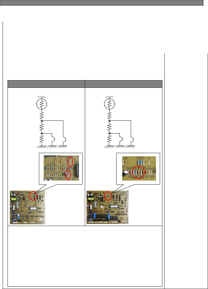
3) “rt” error
Cause : RT-sensor disconnection or short (full down)
Check point : Measure the voltage of “A” part on the Main PCB. If the voltage is 0.5V~4.5V, it is normal.
If the voltage is 0V (short) or 5V (disconnected), change the RT-sensor on the Main PCB How to reset : If RT-sensor is normal, the error is terminated automatically.
A |
A |
|
< FRS(N)-U20IA > |
< FRS(N)-U20DA > |
4) “d1” error
Cause : D-sensor disconnection or short (full down)
Check point : Measure the resistance between both terminals after separating CN8 (or CN15) of the Main PCB. (Refer to the 5-2.)
If D-sensor is disconnected or shorted , change the D-sensor on the evaporator. How to reset : If D-sensor is normal, the error is terminated automatically.
5) Door error (“dF” “dR” “dH” on display)
Cause : in case it senses that door is open for more than 1 hour. Check point : F/R door is opened or not.
6) “C1” error
Cause : in case comp. works for over 3 hours when D-sensor temp. is over -5 Check point : Refrigerant leakage.
7) “F3” error
Cause : in case defrosting return is done by time limit of 80 min
Check point : Measure the resistance between both terminals of the defrost heater. (Assembled with evaporator)
If the resistance is ∞Ω (disconnected) or 0Ω (short) change the
8) “d2” mode (A/S forced defrosting mode)
Push “REFRIGERATOR SET” button 5 times while pushing “FREEZER SET” button simultaneously.
Control : A/S forced defrosting control (Pre-cool is deleted)
If D-sensor temp. is over 10 , the mode is terminated automatically. Refer to the 4-3. .
REMARKS
25

|
|
|
|
|
|
|
|
|
CONTENTS |
REMARKS |
|
|
|
|
|
9) “EI”ERROR
Cause : I-SENSOR disconnection / short
Check point : Measure the resistance between both terminals after separating CN11 of the Main PCB. (Refer to the 5-2.)
If F-sensor is disconnected or shorted , change the I-sensor in the automatic ice maker.
10) “EF” ERROR
Cause : When Flow-sensor ERROR (There is no Pulse during some time)
The number of pulse signal is below 10 by 1 sec during water supply.
Check point : Water supply line
11) “Eg” ERROR
Cause : I-sensor temp (5min after water supply) doesn’t go up.
Check the I-sensor or water supply line.
12) “ES” error (MICRO switch error)
Cause : When it senses 1min continuously
Check the MICRO switch of the dispenser.
13) “Ea” error
Cause : Malfunction of ice drop motor.
Check the motor by pushing test switch.
14) “Eu” error
Cause : Switch (which senses if the ice is full or not) is in error.
Control : When dropping the ice, the motor just rotates 90 degree.
Termination : When the switch is in normal.
15)“EA“ ERROR
Cause : When sensing Ice dropping by time 3 times in level sensor SW Error.
Control : Stop of Ice Maker
Termination : With normal level switch.
Re-input of power or push if icemaker test switch.
16)“Et” ERROR
Cause : Level switch error (No pulse is sensed for some time)
Control : By time (Supply mode is skipped)
Termination : Normal condition.
* When all ERROR CODE is normal, the Refrigerator reset
26

4-11. Summary of Function
4-11-1. FRS(N)-U20IA (Inner Control)
|
INPUT |
|
CONTROL OBJECT |
|
|||
|
|
|
|||||
|
|
|
|
|
|
|
|
|
Each button |
|
Resistance of R-sensor Mid ON/OFF Point |
||||
|
|
|
|
|
|
|
|
|
|
|
CONTENTS |
|
REMARKS |
||
|
|
|
|
|
|
|
|
Element A/S Function |
|
|
|
|
|
||
|
|
|
|
|
|
|
|
|
Forced Defrosting |
|
“FRZ.TEMP” + “REF.TEMP” 5 times |
|
|
|
|
|
|
|
|
|
|
|
|
|
Pull Down |
|
“REF.TEMP”+ “FRZ.DOOR” OPEN/CLOSE 5 times |
|
|
|
|
|
|
|
|
|
|
|
|
|
Demo function |
|
“FRZ.TEMP”+ “FRZ.DOOR” OPEN/CLOSE 5 times |
|
|
|
|
|
|
|
|
|
|
|
|
|
Error display |
|
“REF.TEMP”+ “FRZ.TEMP” 5 times |
|
|
|
|
|
|
|
|
|
|
|
|
|
|
|
|
|
|
|
|
4-11-2. FRS(N)-U20DA/EA/FA/GA (Front PCB)
INPUT |
CONTROL OBJECT |
||
|
|
|
|
Each button |
Resistance of R-sensor Mid ON/OFF Point |
||
|
|
|
|
CONTENTS |
|
REMARKS |
|
|
|
|
|
1.All the modes are started “LOCK” mode (except “FILTER RESET” mode)
2.Element A/S Function
Forced Defrosting |
“FREEZER SET” + “REFRIGERATOR SET” 5 times |
|
|
Reset water filter |
Push “RESET WATER FILTER” for 3 seconds |
|
|
Demo function |
“REFRIGERATOR SET” + “WATER/ICE” 5 times |
|
|
Pull Down |
“REFRIGERATOR SET”+ “FREEZER SET”+ “WATER/ICE”5 times |
|
|
Error display |
“FREEZER SET”+ “SUPER FREEZER” 5 times |
|
|
EEPROM clear |
“WATER/ICE”+ “RESET WATER FILTER” 5times |
|
|
Ice maker test |
“WATER/ICE” + “ICE MAKER LOCK” 5 times |
|
|
27
4-12. Back up Function (FRS(N)-U20DA/EA/FA/GA)
INPUT |
CONTROL OBJECT |
||
|
|
|
|
None |
1. F-FAN, R-FAN, C-FAN |
||
|
|
|
|
CONTENTS |
|
REMARKS |
|
|
|
|
|
1.Filter Exchange Information : Record as a real-time from the point of power input
2.P Factor (Information about Ice Maker)
4-13. Automatic Icemaker ( FRS(N)-U20DA/EA/FA/GA)
INPUT |
CONTROL OBJECT |
|
|
Full ice sensing switch
Ice Maker Lock Ice separating motor
Sensors
CONTENTS |
REMARKS |
|
|
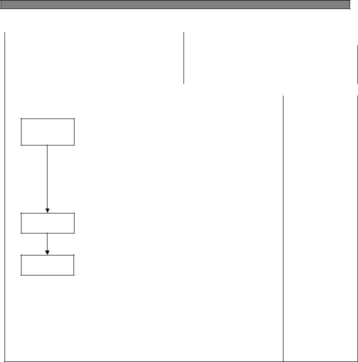
1. Flow of ice making
START
Ice making mode |
Ice is being made |
|
|
(water supply stand by)
Ice separating mode
Water supply mode
Water supply check mode
Ice tray is twisted to separate ice cubes
Water is supplied to ice tray
Check is water is supplied OK.
RETURN
1)Press TEST switch under the Icemaker for more than 1 second and test starts. * Test mode starts from ice separating mode.
* In case test switch has an error of short, test is done only once.
28

CONTENTS
2)With the initial power input, Ice tray turns to be horizontal and ice making mode starts.
3)Control of water hose heater
* Heater is always ON if RT-sensor has an error or RT is below 15 degree. * Heater is always ON for 60 minutes (max. Limit time) if Flow-sensor has an error
4)Water supply stand-by
Condition : if ice is sensed full
Operation : proceeds to Ice making mode (Ice separating and water supply Modes stop)
5) Crusher Function
It stops operation when freezer door is open
It operates if freezer door is closed.
2 Ice making mode
START
|
|
|
|
|
|
|
|
|
|
|
|
|
|
|
|
|
|
|
|
|
|
|
|
NO |
|
NO |
|
I-S -9.5 |
|
|
||||||||
|
130 min passed? |
|
|
YES |
|
|
||||||
|
|
|
|
|
||||||||
|
|
|
|
|
YES |
|
|
|
|
|||
|
|
|
|
|
|
|
|
|
||||
|
|
|
|
|
|
|
||||||
|
|
|
|
|
|
|
|
|
|
|
||
|
|
|
|
|
|
NO |
|
|
|
|
NO |
|
|
I-S 12.5 |
|
15 min passed? |
|
||||||||
|
|
|
|
|
||||||||
|
|
|
|
|
||||||||
|
|
|
|
|
YES |
|
|
YES |
|
|
||
|
|
|
|
|
|
|
|
|
||||
|
|
|
|
|
|
|
|
|
|
|
|
|
|
|
|
|
|
|
|
|
|
|
|
|
|
Ice saparating mode
1)Ice making stops if ice-sensor is below -12.5 after 130 minutes.
2)Ice making also stops if ice-sensor is below -9.5 for 15 minutes, though ice-sensor is not below -12.5 after 130 minutes.
3)In case of ice sensor, ice making stops after 4.8 hours.
REMARKS
29
 Loading...