


Service Manual
Microwave Oven
MODEL : KOG-57470S
KOG-57570S
DAEWOO ELECTRONICS CO., LTD
http : //svc.dwe.co.kr |
June 2000 |

PRECAUTIONS TO BE OBSERVED BEFORE AND DURING SERVICING TO AVOID POSSIBLE EXPOSURE TO EXCESSIVE MICROWAVE ENERGY
(a)Do not operate or allow the oven to be operated with the door open.
(b)Make the following safety checks on all ovens to be serviced before activating the magnetron or other microwave source, and make repairs as necessary: (1) Interlock operation, (2) Proper door closing, (3) Seal and sealing surfaces (arcing, wear, and other damage), (4) Damage to or loosening of hinges and latches, (5) Evidence of dropping or abuse.
(c)Before turning on power to the microwave oven for any service test or inspection within the microwave generating compartments, check the magnetron, wave guide or transmission line, and cavity for proper alignment, integrity, and connections.
(d)Any defective or misadjusted components in the interlock, monitor, door seal, and microwave generation and transmission systems shall be repaired, replaced, or adjusted by procedures described in this manual before the oven is released to the owner.
(e)A microwave leakage check to verify compliance with the Federal performance standard should be performed on each oven prior to release to the owner.
TABLE OF CONTENTS |
|
SAFETY AND PRECAUTIONS ........................................................................................................ |
2 |
1. FOR SAFE OPERATION ............................................................................................................. |
2 |
2. FOR SAFE SERVICE PROCEDURES ........................................................................................ |
2 |
SPECIFICATIONS ............................................................................................................................ |
3 |
EXTERNAL VIEW ............................................................................................................................ |
4 |
1. OUTER DIMENSION .................................................................................................................... |
4 |
2. FEATURE DIAGRAM ................................................................................................................... |
4 |
INSTALLATION ................................................................................................................................ |
5 |
OPERATIONS AND FUNCTIONS ................................................................................................... |
6 |
DISASSEMBLY AND ASSEMBLY .................................................................................................. |
7 |
INTERLOCK MECHANISM AND ADJUSTMENT ........................................................................... |
17 |
TROUBLE SHOOTING GUIDE ........................................................................................................ |
18 |
MEASUREMENT AND TEST ........................................................................................................... |
19 |
1. MEASUREMENT OF THE MICROWAVE POWER OUTPUT ..................................................... |
19 |
2. MICROWAVE RADIATION TEST ................................................................................................ |
20 |
3. COMPONENT TEST PROCEDURE ............................................................................................ |
21 |
WIRING DIAGRAM .......................................................................................................................... |
22 |
EXPLODED VIEW AND PARTS LIST ............................................................................................. |
23 |
1. DOOR ASSEMBLY ...................................................................................................................... |
23 |
2. CONTROL PANEL ASSEMBLY ................................................................................................... |
23 |
3. TOTAL ASSEMBLY ...................................................................................................................... |
23 |
1

SAFETY AND PRECAUTIONS
1. FOR SAFE OPERATION
Damage that allows the microwave energy (that cooks or heats the food) to escape will result in poor cooking and may cause serious bodily injury to the operator.
IF ANY OF THE FOLLOWING CONDITIONS EXIST, OPERATOR MUST NOT USE THE APPLIANCE. (Only a trained service personnel should make repairs.)
(1)A broken door hinge.
(2)A broken door viewing screen.
(3)A broken front panel, oven cavity.
(4)A loosened door lock.
(5)A broken door lock.
The door gasked plate and oven surface should be kept clean.
No greas,soil or spatter should be allowed to build up on these surfaces or inside the oven. DO NOT ATTEMPT TO OPERATE THIS APPLIANCE WITH THE DOOR OPEN.
The micrwave oven has concealead switch to make sure the power is turned off when the door is opened. Do not attempt to defeat them.
DO NOT ATTEMPT TO SERVICE THIS APPLIANCE UNTIL YOU HAVE READ THIS SERVICE MANUAL.
2.FOR SAFE SERVICE PROCEDURES
1.If the oven is operative prior to servicing, a microwave emission check should be performed prior to servicing t he oven.
2.If any certified oven unit is found to servicing, a microwave emission check should be performed prior to servicing the oven.
(a)inform the manufacturer, importer or assembler,
(b)repair the unit at no cost to the owner,
(c)attempt to ascertain the cause of the excessive leakage,
(d)tell the owner of the unit not to use the unit until the oven has been brought into compliance.
3.If the oven operates with the door open, the service person should tell the user not to operate the oven and contact the manafacterer and CDRH innediately.
IMPORTANT
The wire in this mains lead colourred in accordance with the following code.
Green-and-yellow : Earth
|
Blue |
: Neartral |
|
|
|
||
|
Brown. |
: live |
|
|
|
||
|
|
|
|
As the colords of the wires in the manins lead of this appliance may not correspond with the coloured makings identifying the terminals in your plug, proced as follows.
The wire which is coloured green-and-yellow must be connected to the terminal in the plug which is marked with the letter ‘E’, earth symbol or coloured green-and-yellow.
The wire which is coloured blue must be connected to the terminals which is marked with the letter ‘N’or coloured black.
he wire which is coloured brown must be with the letter ‘L’or coloured red.
NOTE:
The oven is desigend for counter-top use only.
2

SPECIFICATIONS
MODEL |
|
KOG-57470S/57570S |
|
|
|
|
|
POWER SUPPLY |
|
230V ~ 50Hz, SINGLE PHASE WITH EARTHING |
|
POWER CON- |
MICROWAVE |
1,200 W |
|
SUMPTION |
|
|
|
GRILL |
1,050 W |
||
|
|||
|
|
|
|
|
COMBINATION |
2,200 W |
|
|
|
|
|
MICROWAVE ENERGY OUTPUT |
800 W |
||
|
|
|
|
MICROWAVE FREQUENCY |
2,450 MHz |
||
|
|
||
OUTSIDE DIMENSIONS(W X H X D) |
465 x 279 x 360 mm (18.3 x 11.0 x 14.2 in) |
||
|
|
|
|
CAVITY DIMENSIONS (W X H X D) |
290 x 208 x 306 mm (11.4 x 8.2 x 12.0 in) |
||
|
|
|
|
NET WEIGHT |
|
Approx. 14kg (30.9 lbs.) |
|
|
|
|
|
TIMER |
|
60 min. Dual Speed |
|
|
|
|
|
FUNCTION SELECTIONS |
MICROWAVE /GRILL / COMBINATION |
||
|
|
|
|
POWER SELECTIONS |
7 LEVELS |
||
|
|
|
|
CAVITY VOLUME |
|
0.7 Cu. Ft. |
|
|
|
|
|
* SPECIFICATIONS ARE SUBJECT TO CHANGE WITHOUT NOTICE.
3

EXTERNAL VIEW
1. OUTER DIMENSION
2. FEATURE DIAGRAM
|
1 |
|
2 |
3 |
4 |
5 |
|
|
|
|
|
|
6 |
|
|
|
|
|
|
7 |
|
|
|
|
|
|
8 |
13 |
12 |
11 |
10 |
9 |
|
|
1)Door seal - Door seal maintains the microwave energy within the oven cavity and prevents microwave leakage.
2)Cover Heater
3)Heating Element
4)Oven cavity
5)Safety interlock system
6)Knob V.P.C - Used to select microwave poer level.
7)Knob timer - Used in setting cooking time for all functions.
8)Metal Rack
9)Coupler - This fits over the shaft in the center of the ovens cavity floor.
This is to remain in the oven for all cooking.
10)Roller guide - This must always be used for cooking together with the glass cooking tray.
11)Glass cooking tray - Made of special heat resistant glass.
Food in a proper receptacle is placed on this tray for cooking. 12) Door viewing screen - Allows viewing of food.
The screen is designed so that light can pass through, but not the microwave. 13) Door hook - When the door is closed, it will automatically shut off.
If the door is opened while the oven is operating, the magnetron will immediately stop operating.
4

 INSTALLATION
1. Steady, flat location
This microwave oven should be set on a steady, flat surface. This microwave oven is designed for counter top use only.
2. Leave space behind and side
All air vents should be kept a clearance. If all vents are covered during operation, the oven may overheat and, eventually, cause oven failure.
3. Away from Radio and TV sets
Poor television reception and radio interference may result if the oven is located closed to a TV, Radio, antenna or feeder and so on.
4. Away from heating appliances and water taps
Keep the oven away from hot air, steam or splash when choosing a place to position it, or the insulation might be adversely affected and breakdowns occur.
5. Power supply
 Check your local power source.
This microwave oven requires a current of approximately 11 amperes, 230Volts, 50Hz grounded outlet.  Power supply cord is about 1.4 meters long.
 The voltage used must be the same as specified on this oven. Using a higher voltage may result in a fire or other accident causing oven damage. Using low voltage will cause slow cooking, We are not responsible for damage resulting from use of this oven with a voltage of amprer fuse other than those specified.
 This appliance is supplied with cable of special type, which, if samaged, must be repaired with cable of same type. Such a cable can be purchased from DAEWOO and must be installed by a Qualified Person.
6.Examine the oven after unpacking for any damage such as:
A misaligned door, broken door or a dent in cavity.
If any of the above are visible, DO NOT INSTALL, and notify dealer immediately.
7.Do not operate the oven if it is colder than room temperature
(This may occur during delivery in cold weather.) Allow oven to become room temperature before operating.
EARTHING INSTRUCTIONS
This appliance must be earthed. In the event of an electrical short circuit , earthing reduces the risk of the electric shock by providing an escape wire for the electric current. This applicance is equipped with a cord having a reathing wire with a earthing plug. The plug must be plugged into an outlet that is properly installed ant earthed.
WARNING
Improper use of the earthing plug can result in a risk of electric shock. Consult a qualified electrician or serviceman if the earthing instructions are not completely understood, or if doubt exists as to whether the appliance is properly earthed, and either: If it is necessary to use an extension cord, use only a 3-wire extension cord that has a 3-blade earthing plug, and a 3-slot receptacle that will accpt the plug on the appliance. The marked rating of the extension cord should be equal to or greater than the electrical rating of the appliance, or Do not use an extension cord.
5
 OPERATIONS AND FUNCTIONS
1. Connect the main lead to an electrical outlet.
2. After placing the food in a suitable container,
open the oven door and put it on the glass tray.
The glass tray must always be in place during cooking.
3. Close the door securely.
4. Choose cooking power level by setting V.P.C knob to
the desired position.
5. Determine cooking time. Consult cookbook for recipe timing.
Oven light turns on and cooling fan starts to operate.
Microwave cooking starts. |
NOTE |
|
6. You may open the door while the oven is operating. |
1. When setting timer for less than 2 minutes, turn the |
|
As soon as the door is opened, the safety mechanisms stop the |
||
timer pass 2 minutes and then return to the correct |
||
generation of microwave power and the operation of cooking |
||
timer setting. |
||
timer. If you wish to change the time during cooking, |
||
2. Various clicking noises may be heard when turning |
||
simply adujst the timer to the desired time. |
||
V.P.C knob. This is normal and does not affect the |
||
7. When the timer reaches zero, a bell will ring and the unit will turn |
||
operation of your microwave oven. |
||
off. Oven light turns off. If additional cooking time is needed and |
||
|
||
the door is closed, the oven will automatically start when the timer is reset. |
||
 To set MICROWAVE cooking
Set the variable power selector to the desired power level.
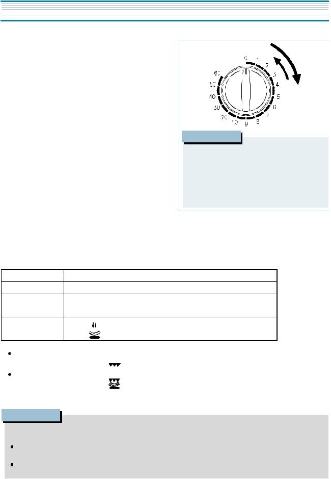
POWER LEVEL |
SYMBOL |
APPROXIMATE PERCENTAGE OF POWER |
HIGH |
MAX |
100% |
MED-HIGH |
700W |
88% |
MEDIUM |
580W |
73% |
DEFROST |
*** |
41% |
HEAT |
|
26% |
To set GRILL cooking |
|
Set the POWER SELECTOR to the |
(grill) position. |
To set COMBI cooking |
|
Set the POWER SELECTOR to the |
(combi) position. |

 NOTE
NOTE
When using the GRILL or COMBI mode;
 Do not open the door so open, the temperature inside the oven decrese and the cooking may not be completed in setting time.
Never touch the oven window and metal interior of the oven when taking food in and out, because the temperature inside the oven and door is very high.
When using these mides, be careful as the tray will be hot to touch, use oven gloves or pot holders while handling tray.
6
DISASSEMBLY AND ASSEMBLY
Cautions to be observed when trouble shooting.
Unlike many other appliances, the microwave oven is high-voltage, high-current equipment. It is completely safety during normal operation.
However, carelessness in servicing the oven can result in an electric shock or possible danger from a short circuit. You are asked to observe the following precautions carefully.
1.Always remove the power plug from the outlet before servicing.
2.Use an insulated scredriver and ware rubber gloves when servicing the high voltage side.
3.Discahrge the high voltage capacitor before touching any oven components or wiring.
(1) Check the grounding.
Do not operate on a 2-wire extension cord.
The microwave oven is designed to be used with grounded.
It is imperative, therefore, to make sure it is grounded properly before beginning repair work.
(2) Warning about the electric charge in the high voltage capacitor. For about 30 seconds after the operation stopped and electric charge remains in the high voltage capacitor.
When replacing or checking parts, short between oven chassis and the negative high terminal of the high voltage
capacitor, by using a properly insulated screwdriver to discharge.
|
|
|
|
|
|
|
|
|
|
|
|
|
|
|
|
|
|
|
|
|
|
|
|
|
|
|
|
|
|
|
|
|
|
|
|
|
|
|
|
|
|
|
|
|
|
|
|
|
|
|
|
|
|
|
|
|
|
|
|
|
|
|
|
|
|
|
|
|
|
|
|
|
|
|
|
|
|
|
|
|
|
|
|
|
|
|
|
|
|
|
4. |
When the 15A fuse is blown out due to the operation of the monitor switch; |
|
|
|
|
|
|
|
|
|
|
|
|
|
|
|
|
|
|
|
|
|
|
|
|
|
|
|
|
|
|
|||||||||||||||||||||||||||||||||||||||||||||||||||||||||||
|
|
|
|
|
|
|
|
|
|
|
|
|
|
|
|
|
|
|
|
|
|
|
|
|
|
|
|
|
|
|||||||||||||||||||||||||||||||||||||||||||||||||||||||||||||
|
|
|
replace primary interlock switch, secondary interlock switch and interlock |
|
|
|
|
|
|
|
|
|
|
|
|
|
|
|
|
|
|
|
|
|
|
|
|
|
|
|
|
|
|
|
|
|
|
|
|
|||||||||||||||||||||||||||||||||||||||||||||||||||
|
|
|
|
|
|
|
|
|
|
|
|
|
|
|
|
|
|
|
|
|
|
|
|
|
|
|
|
|
|
|
||||||||||||||||||||||||||||||||||||||||||||||||||||||||||||
|
|
|
|
|
|
|
|
|
|
|
|
|
|
|||||||||||||||||||||||||||||||||||||||||||||||||||||||||||||||||||||||||||||
|
|
|
|
|
|
|
|
|
|
|
|
|
|
|
|
|
|
|
|
|
|
|
|
|
|
|
|
|
|
|
|
|
|
|
|
|
|
|||||||||||||||||||||||||||||||||||||||||||||||||||||
|
|
|
monitor switch. |
|
|
|
|
|
|
|
|
|
|
|
|
|
|
|
|
|
|
SHORT |
|
|
|
|
||||||||||||||||||||||||||||||||||||||||||||||||||||||||||||||||
|
|
|
|
|
|
|
|
|
|
|
|
|
|
|
|
|||||||||||||||||||||||||||||||||||||||||||||||||||||||||||||||||||||||||||
5. |
After repair or replacement of parts, make sure that the screws are properly |
|
|
|
|
|
|
|
|
|
|
|
|
|||||||||||||||||||||||||||||||||||||||||||||||||||||||||||||||||||||||||||||
|
|
|
tightened, and all electrical connections are tightened. |
|
|
|
|
|
|
|
|
|
|
|
|
|
|
|
|
|
|
|
|
|||||||||||||||||||||||||||||||||||||||||||||||||||||||||||||||||||
|
|
|
|
|
|
|
|
|
|
|
|
|
|
|
||||||||||||||||||||||||||||||||||||||||||||||||||||||||||||||||||||||||||||
|
|
|
|
|
|
|
|
|
|
|
|
|
|
|
||||||||||||||||||||||||||||||||||||||||||||||||||||||||||||||||||||||||||||
6. |
Do not operate without cabinet. |
|
|
|
|
|
|
|
|
|
|
|
|
|
|
|
|
|
|
|
|
|
|
|
|
|
|
|||||||||||||||||||||||||||||||||||||||||||||||||||||||||||||||
|
|
|
|
|
|
|
|
|
|
|
|
|
|
|
|
|
|
|
|
|
|
|
|
|
|
|||||||||||||||||||||||||||||||||||||||||||||||||||||||||||||||||
|
|
|
|
|
|
|
|
|
|
|
|
|
|
|
|
|
|
|
|
|
|
|
|
|
|
|
|
|
|
|
|
|
|
|
|
|
|
|
|
|
|
|
|
|
|
|
|
|
|
|
|
|
|
|
|
|
|
|
|
|
|
|
|
|
|
|
|
|
|
|
|
|
|
|
|
|
|
|
|
|
|
|
|
|
|
|
|
|
|
|
|
|
|
|
|
|
|
|
|
|
|
|
|
|
|
|
|
|
|
|
|
|
|
|
|
|
|
|
|
|
|
|
|
|
|
|
|
|
|
|
|
|
|
|
|
|
|
|
|
|
|
|
|
|
|
|
|
|
|
|
|
|
|
|
|
|
|
|
|
|
|
|
|
|
|
|
|
|
|
|
|
|
|
|
|
|
|
|
|
|
|
CAUTION : Service personnel should remove their watches whenever working close to or replacing the magnetron.
CAUTION : When servicing th appliance, need a care of touching or replacing high potential parts because of electrical shock or exposing microwave. These parts are as follows - HV Transformer, Magnetron, HV Capacitor, HV Diode, HV Fuse.
7
DISASSEMBLY AND ASSEMBLY
1. To remove cabinet
1) Remove three screws on cabinet back.
2) Push the cabinet backward.
2. To remove door assembly
1) Remove two screws which secure the stopper hinge top. 2) Remove the door assembly from top plate of cavity.
3) Reverse the above for reassembly.
NOTE : After replacing the door assembly, perform a check of correct alignment with the hinge and cavity front plate.
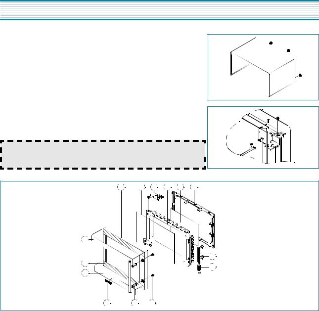
3. To remove door parts.
A01 A02
A02 A03
A03 A04
A04 A05 A06
A13
A07
A14
A08
A12
DOOR ASSEMBLY
KOG-57470S : 3511712140
A11 A10 A09
REF NO. |
PART CODE |
PART NAME |
DESCRIPTION |
Q’TY |
REMARK |
A01 |
3512203850 |
FRAME DOOR |
ABS XR-401, H-2938 |
1 |
|
|
|
|
|
|
|
A02 |
3517005620 |
BARRIER-SCREEN*O |
TEMP GLASS T3.2 MIRROR |
1 |
|
|
|
|
|
|
|
A03 |
3515204100 |
STOPPER HINGE*T AS |
KOR-63150S |
1 |
|
|
|
|
|
|
|
A04 |
3511706120 |
DOOR PAINTING AS |
KOR-634R0S |
1 |
|
|
|
|
|
|
|
A05 |
3517002800 |
BARRIER-SCREEN*I |
PE 0.1T |
1 |
|
|
|
|
|
|
|
A06 |
3512300200 |
GASKET DOOR |
PP |
1 |
|
|
|
|
|
|
|
A07 |
3513100730 |
HOOK |
POM BLACK |
1 |
|
|
|
|
|
|
|
A08 |
3515101310 |
SPRING HOOK |
HSW-3 |
1 |
|
|
|
|
|
|
|
A09 |
7001503310 |
SCREW MACHINE |
PAN 5X33 MFZN |
2 |
|
|
|
|
|
|
|
A10 |
3512603210 |
HANDLE DOOR |
STEEL NI + CR |
1 |
|
|
|
|
|
|
|
A11 |
3511601500 |
DECORATOR LOGO |
AL T1.5 |
1 |
|
|
|
|
|
|
|
A12 |
3511604610 |
DECORATOR DOOR*U |
STS T0.6 |
1 |
|
|
|
|
|
|
|
A13 |
3511604600 |
DECORATOR DOOR*T |
STS T0.6 |
1 |
|
|
|
|
|
|
|
A14 |
3516003940 |
SPECIAL DOUBLE TAPE |
SI-161 T0.15 27MM |
1 |
|
|
|
|
|
|
|
8
 Loading...