


 Loading...
S/M No. : R981C0S001
Service Manual
Microwave Oven
Model: KOC-971C0S
KOC-971C2S
KOC-981C1S
KOC-981C2S
DAEWOO ELECTRONICS CO., LTD.

PRECAUTIONS TO BE OBSERVED BEFORE AND
DURING SERVICING TO AVOID POSSIBLE
EXPOSURE TO EXCESSIVE MICROWAVE ENERGY
(a) Do not operate or allow the oven to be operated w ith the door open.
(b)M ake the following safety checks on all ovens to be serviced before activating the m agnetron or other microwave source, and m ake repairs as necessary: (1) Interlock operation, (2) Proper door closing, (3) S eal and sealing surfaces (arcing, wear, and other damage), (4) Damage to or loosening of hinges and latches, (5) Evidence of dropping or abuse.
(c)Before turning on power to the m icrow ave oven for any service test or inspection within the microwave generating com partments, check the magnetron, wave guide or transmission line, and cavity for proper alignment, integrity, and connections.
(d)Any defective or misadjusted components in the interlock, monitor, door seal, and microwave generation and transmission systems shall be repaired, replaced, or adjusted by procedures described in this m anual before the oven is released to the ow ner.
(e)A m icrowave leakage check to verify com pliance with the Federal performance standard should be performed on each oven prior to release to the owner.

|
|
|
|
|
|
|
|
|
|
|
|
|
|
! ! |
|
|
|
! ! |
# |
! |
|
|
|
!
!
! |
# |
! |
$ |

SAFETY AND PRECAUTIONS
1. FOR SAFE OPERATION
Damage that allows the microwave energy (that cooks or heats the food) to escape will result in poor cooking and may cause serious bodily injury to the operator.
IF ANY OF THE FOLLOWING CONDITIONS EXIST, OPERATOR MUST NOT USE THE APPLIANCE. (Only a trained service personnel should make repairs.)
(1)A broken door hinge.
(2)A broken door viewing screen.
(3)A broken front panel, oven cavity.
(4)A loosened door lock.
(5)A broken door lock.
The door gasket plate and oven cavity surface should be kept clean.
No grease, soil or spatter should be allowed to build up on these surfaces or inside the oven.
DO NOT ATTEMPT TO OPERATE THIS APPLIANCE WITH THE DOOR OPEN.
The microwave oven has concealed switches to make sure the power is turned off when the door is opened. Do not attempt to defeat them.
DO NOT ATTEMPT TO SERVICE THIS APPLIANCE UNTIL YOU HAVE READ THIS SERVICE MANUAL.
2. FOR SAFE SERVICE PROCEDURES
1.If the oven is operative prior to servicing, a microwave emission check should be performed prior to servicing the oven.
2.If any certified oven unit is found to servicing, a microwave emission check should be performed prior to servicing the oven.
(1)inform the manufacturer, importer or assembler,
(2)repair the unit at no cost to the owner,
(3)attempt to ascertain the cause of the excessive leakage,
(4)tell the owner of the unit not to use the unit until the oven has been brought into compliance.
3.If the oven operates with the door open, the service person should tell the user not to operate the oven and contact the manufacturer immediately.
IMPORTANT
The w ire in this m ains lead coloured in accordance with the follow ing code.
G reen-and-yellow |
: Earth |
Blue |
: N eutral |
Brow n |
: Live |
As the colours of the w ires in the m ains lead of this appliance m ay not correspond w ith the coloured m arkings identifying the term inals in your plug, proceed as follow s.
The w ire which is coloured green-and-yellow m ust be connected to the term inal in the plug w hich is m arked w ith the letter 'E' , earth sym bol or coloured green-and-yellow.
The wire which is coloured blue must be connected to the terminal which is marked with the letter 'N' or coloured black. The wire which is coloured brown must be connected to the term inal w hich is marked with the letter 'L' or coloured red.
NOTE
This oven is designed for counter-top use only.

SPECIFICATIONS
M O D E L |
|
K O C-971C0S |
|
KO C -971C 2S |
|
|
|
|
|
||
P OW E R SU P P LY |
230V ~50H z |
|
230V ~50Hz |
||
|
|
|
|
|
|
|
|
M IC R OW AV E |
1450W |
|
1450W |
|
|
|
|
|
|
|
|
G R ILL |
1200W |
|
1200W |
|
|
|
|
|
|
|
|
CO N V EC TIO N |
1550W |
|
1550W |
|
|
|
|
|
|
P O W ER C O NS U M PTIO N |
|
P RO G R A M C O OK |
1850W |
|
1850W |
|
|
C O M B IN ATION |
2600W (S im ultaneous) |
|
1550W (S equential) |
|
|
|
|
|
|
M IC R O WAV E EN E R G Y O U TPU T |
950W (IE C 705) |
|
950W (IEC 705) |
||
|
|
|
|
||
M IC R OW AV E FR E QU E N CY |
2450M Hz |
|
2450M H z |
||
|
|
|
|||
O U TS ID E DIM E NS IO N S (W X H X D ) |
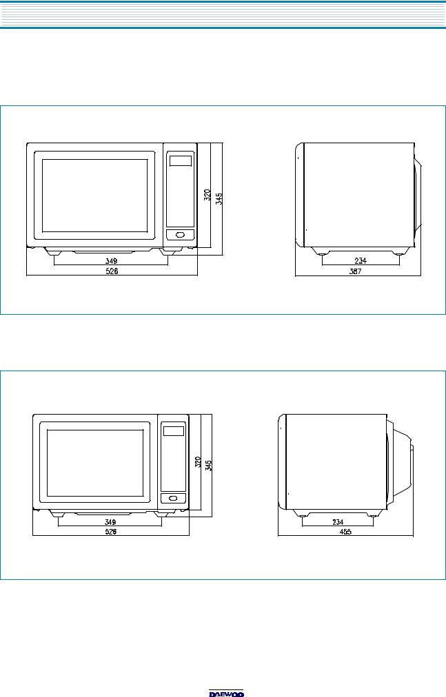
526 x 345 x 387 m m (20.7 x 13.6 x 15.2 in.) |
||||
|
|
||||
C AV IT Y D IM E NS IO N S (W X H X D) |
335 x 255 x 339 m m (13.2 x 10.0 x 13.3 in.) |
||||
|
|
||||
N E T W E IG HT |
A P P RO X . 20 K g (44.2 lbs.) |
||||
|
|
|
|
||
TIM E R |
|
|
60 m inutes |
||
|
|
||||
FU N CTIO N S E LE CTIO N S |
M IC R OW AV E /G R ILL/C O N VE C TION /C O M B I |
||||
|
|
|
|||
P O W E R SE LE C TIO N S |
|
10 LEV E LS |
|||
|
|
|
|||
C AV ITY V O LU M E |
|
1.0 C u.Ft. |
|||
|
|
|
|
|
|
|
|
|
|
|
|
M OD E L |
|
K O C-981C1S |
|
KO C -981C 2S |
|
|
|
|
|
||
P OW E R SU P P LY |
230V ~50H z |
|
230V ~50Hz |
||
|
|
|
|
|
|
|
|
M IC R OW AV E |
1450W |
|
1450W |
|
|
|
|
|
|
|
|
G R ILL |
1200W |
|
1200W |
|
|
|
|
|
|
|
|
CO N V EC TIO N |
1550W |
|
1550W |
|
|
|
|
|
|
P O W ER C O NS U M PTIO N |
|
P RO G R A M C O OK |
1850W |
|
1850W |
|
|
|
|
|
|
|
|
C O M B IN ATION |
2600W (S im ultaneous) |
|
1550W (S equential) |
|
|
|
|
|
|
M IC R O WAV E EN E R G Y O U TPU T |
1000W (IE C705) |
|
1000W (IEC 705) |
||
|
|
|
|
||
M IC R OW AV E FR E QU E N CY |
2450M Hz |
|
2450M H z |
||
|
|
|
|||
O U TS ID E DIM E NS IO N S (W X H X D ) |
526 x 345 x 455 m m (20.7 x 13.6 x 17.9 in.) |
||||
|
|
||||
C AV IT Y D IM E NS IO N S (W X H X D) |
335 x 250 x 339 m m (13.2 x 9.8 x 13.3 in.) |
||||
|
|
||||
N E T W E IG HT |
A P P RO X . 21 K g (46.3 lbs.) |
||||
|
|
|
|
||
TIM E R |
|
|
60 m inutes |
||
|
|
||||
FU N CTIO N S E LE CTIO N S |
M IC R OW AV E /G R ILL/C O N VE C TION /C O M B I |
||||
|
|
|
|||
P O W E R SE LE C TIO N S |
|
10 LEV E LS |
|||
|
|
|
|||
C AV ITY V O LU M E |
|
1.0 C u.Ft. |
|||
|
|
|
|
|
|
SPECIFICATIONS ARE SUBJECT TO CHANGE WITHOUT NOTICE.
EXTERNAL VIEW
1. OUTER DIMENSION
KOC-971C
KOC-981C

EXTERNAL VIEW
2. FEATURE DIAGRAM
KOC-971C
1.Door seal - Door seal maintains the microwave energy within the oven cavity and prevents microwave leakage.
2.Door hook - When the door is closed, it will automatically shut. If the door is opened while the oven is operating, the magnetron will immediately stop operating.
3.Door viewing screen - Allows viewing of food. The screen is designed so that light can pass through, but not the microwave.
4.Top heater - Turns on when convection, grill and combi cooking is selected.
5.Oven lamp - Automatically turns on during oven operating.
6.Safety interlock system
7.Control panel
8.Turntable tray - Rotates during cooking and ensure even distribution of Microwaves. It can also be used as a cooking utensil.
9.Oven front plate
10.Rotating base - This fits over the shaft in the center of the ovens cavity floor.
This is to remain in the oven for all cooking. It should only be removed for cleaning.
11.Under heater
12.Door opening button - To open the door, push the door opening button.

EXTERNAL VIEW
KOC-981C
1. Door seal - Door seal maintains the microwave energy within the oven cavity and prevents microwave leakage. 2. Door hook - When the door is closed, it will automatically shut. If the door is opened while the oven is operating,
the magnetron will immediately stop operating.
3.Door viewing screen - Allows viewing of food. The screen is designed so that light can pass through, but not the microwave.
4.Top heater - Turns on when convection, grill and combi cooking is selected.
5.Oven lamp - Automatically turns on during oven operating.
6.Safety interlock system
7.Control panel
8.Turntable tray - Rotates during cooking and ensure even distribution of Microwaves. It can also be used as a cooking utensil.
9.Oven front plate
10.Rotating base - This fits over the shaft in the center of the ovens cavity floor.
This is to remain in the oven for all cooking. It should only be removed for cleaning.
11.Under heater
12.Metal rack
13.Convection Outlet & Fan
14.Door openning button - To open the door, push the door opening button.

INSTALLATION
1.Steady, flat location
This microwave oven should be set on a steady, flat surface. This microwave oven is designed for counter top use only.
2.Leave space behind and side
All air vents should be kept a clearance. If all vents are covered during operation, the oven may overheat and, eventually, cause failure.
3.Away from radio and TV sets
Poor television reception and radio interference may result if the oven is located close to a TV, radio, antenna or feeder and so on. Position the oven as far from them as possible.
4.Away from heating appliances and water taps
Keep the oven away from hot air, steam or splash when choosing a place to position it, or the insulation might be adversely affected and breakdowns occur.
5.Power supply
Check your local power source. This microwave oven requires a current of approximately 13amperes, 230 Volts, 50 Hz. Power supply cord is about 1.2 meters long.
The voltage used must be the same as specified on this oven. Using a higher voltage may result in a fire or other accident causing oven damage. Using low voltage will cause slow cooking. We are not responsible for damage resulting from use of this oven with a voltage of ampere fuse other than those specified.
This appliance is supplied with cable of special type, which, if damaged, must be repaired with cable of same type. Such a cable can be purchased from DAEWOO and must be installed by a Qualified Person.
6.Examine the oven after unpacking for any damage such as: A misaligned door, broken door or a dent in cavity.
If any of the above are visible, DO NOT INSTALL, and notify dealer immediately.
7.Do not operate the oven if it is colder than room temperature.
(This may occur during delivery in cold weather.) Allow the oven to become room temperature before operating.
EARTHING INSTRUCTIONS
This appliance must be earthed. In the event of an electrical short circuit, earthing reduces the risk of the electric shock by providing an escape wire for the electric current. This appliance is equipped with
a cord having a earthing wire with a earthing plug. The plug must be plugged into an outlet that is properly installed and earthed.
WARNING
Im proper use of the earthing plug can result in a risk of electric shock.
C onsult a qualified electrician or servicem an if the earthing instructions are not com pletely understood, or if doubt exists as to w hether the appliance is properly earthed, and either:
If it is necessary to use an extension cord, use only a 3-w ire extension cord that has a 3-blade earthing plug, and a 3-slot receptacle that w ill accept the plug on the appliance.
The m arked rating of the extension cord should be equal to or greater than the electrical rating of the appliance, or D o not use an extension cord.

CONTROL PANEL
When blinking, the oven is operating in "COMBI" cooking mode.
When blinking, the oven is operating in "GRILL" cooking mode.
When blinking, the oven is operating in "MICROWAVE" cooking mode.
When blinking, the oven is operating in "PROGRAM COOK" cooking mode.
When blinking, the oven is operating in "PIE" cooking mode.
When blinking, the oven is operating in "CONVECTION" cooking mode.
Microwave Power Level-
Used to select the variable microwave power level. If this button is pressed for more than 1.3 sec, number is scrolled up automatically.
Clock Pad-
Used to set and recall the time of day.
Stop/Clear Pad-
Used to pause and clear all information manually put into the oven.
Used to open the door.
DEFROST
MW |
GLILL |
COMBI |
WEIGHT - TIME |
|
|
|
|
PROGRAM PIE |
TEMP |
KG |
|
COOK |
COOK |
|
|
10min |
1min |
10sec |
|
1Kg |
0.1Kg |
|
|
M/W |
|
TE MP |
|
GR ILL |
|
COMBI |
|
Weight/Time |
|
PIE |
|
DEFROST |
|||
|
|||
1. Roast Beef |
|
|
|
2. Roast Pork |
PROGRAM |
||
3. Roast Chicken |
|||
|
COOK |
||
4. Fish Fillet |
|
||
|
|
||
5. Vegetable |
|
|
|
SPEEDY COOK
STOP/ |
START |
|
CLEAR |
||
|
When blinking, the oven is operating in "WEIGHT DEFROST" cooking mode.
When blinking, the oven is operating in "TIME DEFROST" cooking mode.
When blinking, the oven is operating in weght input mode.
Numerals are used to enter the cooking time and/or time of day and weight input.
Temperature PadUsed to set desired
temperature. If this button is pressed for more than 1.3 sec, number is scrolled up automatically.
Function Pads-
Used to select desired cooking function.
 M/W : MICROWAVE
 GRILL
GRILL
 DEFROST : TIME or WEIGHT DEFROST
 TEMP : CONVECTION
 COMBI : COMBINATION
 PIE
PIE
 PROGRAM COOK
Speedy Cook PadUsed to program quickly cooking time in 30 sec increments.
Start Pad-
Used to start the selected cooking cycle.
DISASSEMBLY AND ASSEMBLY
Cautions to be observed when trouble shooting.
Unlike many other appliances, the microwave oven is high-voltage, high-current equipment.
It is completely safety during normal operation.
However, carelessness in servicing the oven can result in an electric shock or possible danger from a short circuit. You are asked to observe the following precautions carefully.
1.Always remove the power plug from the outlet before servicing.
2.Use an insulated screwdriver and ware rubber gloves when servicing the high voltage side.
3.Discharge the high voltage capacitor before touching any oven components or wiring.
(1)Check the earthed.
Do not operate on a two-wire extension cord.
The microwave oven is designed to be used with earthed.
It is imperative, therefore, to makes sure it is earthed properly before beginning repair work.
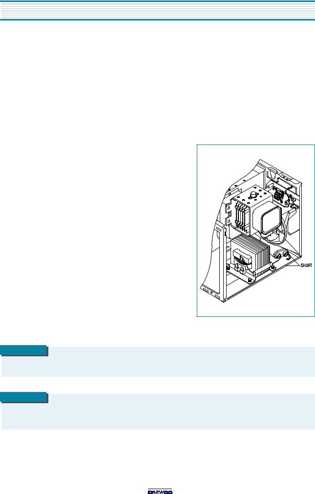
(2) Warning about the electric charge in the high voltage capacitor.
For about 30 seconds after the operation stopped and electric charge remains in the high voltage capacitor.
When replacing or checking parts, short between oven chassis and the negative high terminal of the high voltage capacitor,
by using a properly insulated screwdriver to discharge.
4. When the 15A fuse is blown out due to the operation of the monitor switch; replace primary interlock switch, secondary interlock
switch and interlock monitor switch.
5.After repair or replacement of parts, make sure that the screws are properly tightened, and all electrical connections are tightened.
6.Do not operate without cabinet.
CAUTION
Service personnel should rem ove their w atches w henever w orking close to or replacing the m agnetron.
WARNING
W hen servicing the appliance, need a care of touching or replacing high potential parts because of electrical shock or exposing m icrow ave. These parts are as follow s - HV Transform er, M agnetron, H V C apacitor, H V D iode.
DISASSEMBLY AND ASSEMBLY
1.To remove cabinet
(1)Remove four screws on cabinet back.
(2)Push the cabinet backward.
2.To remove guide wind assembly
(1)Remove two screws for earthing and for fixing to rear-plate.
(2)Remove the noise filter from the guide wind.
(3)Pull the fan from the motor shaft.
(4)Remove two screws which secure the motor shaded pole.
(5)Remove the motor shaded pole.
(6)Reverse the above steps for reassembly.

DISASSEMBLY AND ASSEMBLY
3.To remove H.V.transformer
(1)Remove four screws which secure the H.V.transformer to the base plate.
(2)Remove the H.V.transformer.
(3) Reverse the above steps for reassembly.
4. To remove high voltage capacitor
(1) Remove a screw which secure the grounding ring terminal of the H.V. diode and the capacitor holder.
(2) Remove the H.V. diode from the capacitor holder.
(3) Reverse the above steps for reassembly.
High voltage circuit wiring

DISASSEMBLY AND ASSEMBLY
5.To remove magnetron
(1)Remove three screws which secure the magnetron.
(2)Remove the magnetron.
(3)Reverse the above steps for reassembly.
CAUTION
N ever install the m agnetron w ithout the m etallic gasket plate which is packed w ith each magnetron to prevent
m icrow ave leakage. W henever repair w ork is carried out on m agnetron, check the m icrow ave leakage. It shall not exceed 4m W /cm 2 for a fully assem bled oven with door norm ally closed.

DISASSEMBLY AND ASSEMBLY
6.To remove control panel assembly
(1)Remove a screw which secure the control panel assembly to the oven front plate.
At the same time, draw forward the control panel assembly from the oven front plate.
(2)Disconnect membrane tail from the connector of the PCB main assembly.
(3)Remove three screws which secure the PCB main assembly to control panel.
REF NO. |
PART CODE |
PART NAM E |
DESCRIPTION |
QTY |
REMARK |
B 01 |
3516715100 |
C O N T R O L-PA N E L |
A B S |
1 |
|
|
|
|
|
|
|
B 02 |
441B655072 |
S P R ING D OO R B UTTO N |
H S W R |
1 |
|
|
|
|
|
|
|
B 03 |
3516905010 |
B U TTO N D O O R O P EN |
A B S |
1 |
|
|
|
|
|
|
|
B 04 |
3518518200 |
S W ITC H M E M BR A N E |
K O C-971C /981C |
1 |
|
|
|
|
|
|
|
|
P K M PM S Q 100 |
P C B M A IN A S |
KO C -971C 0S /971C 2S |
|
|
|
|
|
|
|
|
B 05 |
P K M PM S Q 150 |
P C B M A IN A S |
K OC -981C1S |
1 |
|
|
|
|
|
|
|
|
P K M PM S Q 160 |
P C B M A IN A S |
K OC -981C2S |
|
|
|
|
|
|
|
|
B 06 |
7S 341W 40B1 |
S C R E W S P EC IA L |
T2S PAN 4X12 PW SE MFZN |
3 |
|
|
|
|
|
|
|
B 07 |
3513702300 |
LEV E R DO O R O P E N |
P O M |
1 |
|
|
|
|
|
|
|
DISASSEMBLY AND ASSEMBLY
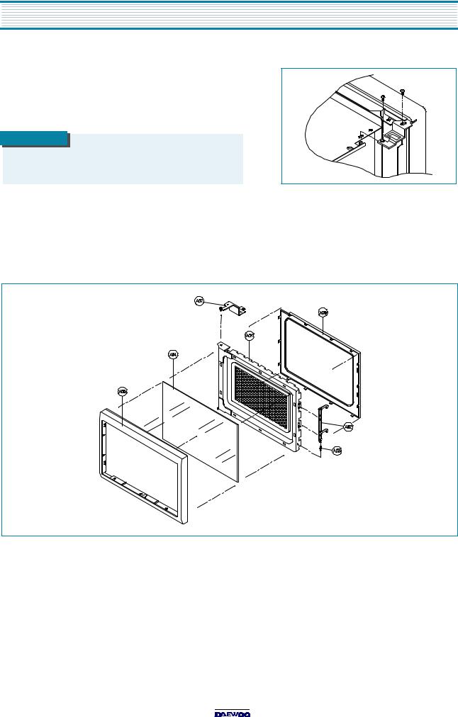
7.To remove door assembly
(1)Remove two screws which secure the stopper hinge top.
(2)Remove the door assembly from top plate of cavity.
(3)Reverse the above steps for reassembly.
NOTE
After replacing the door assem bly, perform a check of correct alignm ent with the hinge and cavity front plate.
8.To remove door parts
(1)Remove the gasket door.
(2)Remove the door seal ass’y.
(3)Remove the hook and spring.
(4)Remove the barrier-screen *o.
REF. NO. |
PART CODE |
PART NAM E |
DESCRIPTION |
QTY |
REMARK |
A 01 |
3511708400 |
D O O R S E A L A S |
K O C -971C 0S |
1 |
|
|
|
|
|
|
|
A 02 |
3513100900 |
HO O K |
PO M |
1 |
|
|
|
|
|
|
|
A 03 |
3515101300 |
S P R IN G H OO K |
PW 1 |
1 |
|
|
|
|
|
|
|
A 04 |
3517004000 |
B AR R IE R-S C RE E N *O |
TE M P E R E D G LA SS T3.2 |
1 |
|
|
|
|
|
|
|
A 05 |
3512203300 |
FR A M E D OO R |
A B S X R -401 |
1 |
|
|
|
|
|
|
|
A 06 |
3512300800 |
G A S KE T D OO R |
PB T |
1 |
|
|
|
|
|
|
|
A 07 |
3515203600 |
S TO P PE R H ING E *T A S |
K O C -970T1S |
1 |
|
|
|
|
|
|
|
Loading...